A Fleet of MEC UAVs to Extend a 5G Network Slice for Video Monitoring with Low-Latency Constraints

Department of Electrical, Electronic and Computer Engineering (DIEEI), University of Catania V. le Doria 6, 95125 Catania, Italy
*
Author to whom correspondence should be addressed.
J. Sens. Actuator Netw. 2019, 8(1), 3; https://0-doi-org.brum.beds.ac.uk/10.3390/jsan8010003
Submission received: 29 November 2018
/
Revised: 17 December 2018
/
Accepted: 22 December 2018
/
Published: 1 January 2019
(This article belongs to the Special Issue Softwarization at the Network Edge for the Tactile Internet)
Abstract
:In the last decade, video surveillance systems have become more and more popular. Thanks to a decrease in price of video camera devices and the diffusion of cheap small unmanned aerial vehicles (UAVs), video monitoring is today adopted in a wide range of application cases, from road traffic control to precision agriculture. This leads to capture a great amount of visual material to be monitored and screened for event detection. However, information that is gathered from a platform of video monitoring UAVs may produce high-volume data, whose processing is unfeasible to be done locally by the same UAVs that perform monitoring. Moreover, because of the limited bandwidth of wireless links connecting UAVs to computing infrastructures that are installed on ground, offloading these data to edge clouds renders these platforms infeasible for video analysis applications with low-latency requirements. The target of this paper is to extend a 5G network slice for video monitoring with a Flying Ad-hoc NETwork (FANET) constituted by UAVs with multi-access edge computing (MEC) facilities (MEC UAVs), flying very close to the layer of UAVs monitoring the area of interest. A policy for mutual help among MEC UAVS is defined in order to increase the performance of the whole aerial MEC platform, so further reducing end-to-end latency between sources and actuators, and increasing system reliability. A use case is considered for a numerical analysis of the proposed platform.
1. Introduction
Nowadays, video surveillance systems are widely used in a very huge number of scenarios, from controlling urban and rural areas and preventing acts of crime, to performing rescue operations, traffic surveillance, and forest fire monitoring [1,2,3,4,5]. In the last few years, autonomous Unmanned Aerial Vehicles (UAVs), thanks to their mobility and reduced costs, have gained considerable attention, providing an effective alternative to both ground surveillance, being able to capture images of distant targets in larger areas and with different angles, and traditional manned solutions due to their greater safety.
For contexts in which a frequent or continuous check of an interest area is required, small-scale UAVs can be used, thanks to their rapid deployment time and their capability to perform low-altitude flights. For persistent surveillance tasks when the limited duration of batteries could limit the mission lifetime, the use of multiple small-scaled UAVs organized in flocks has been considered [6,7,8]. A study in [9] presents the capabilities of such systems in analyzing digital images of the terrain and identifying potential invasion, unauthorized changes in land, and deforestation in some special urban areas.
Nevertheless, as information gathered from a surveillance UAV may include high-volume sensor data, such as live video, and since the processing of these data is computationally expensive to be performed locally by the same small-scaled UAVs, in these cases, they should be continuously offloaded to an external data center. For this purpose, highly uninterrupted communications bandwidth should be required. Since the maximum communication range is typically limited, especially when smaller and lower-cost UAVs are used, UAV applications tend to require line-of-sight (LOS) communications with fixed network access points. The problem of achieving LOS, which is problematic in mountainous or urban areas, cannot be alleviated by increasing altitude when small UAVs are used, since they are unable to ascend to sufficient altitude to achieve LOS to both the target and the base station.
An additional problem is present in scenarios with low-latency requirements, where end-to-end (e2e) delays in receiving services from remote clouds are not only due to the propagation time along the Internet connections, but also, in the case of big amounts of data, to the available bandwidth on both the radio access network and the backhaul networks.
A solution to the above problems can be found in the fifth generation (5G) mobile systems, which will encompass the Software Defined Networks and Network Functions Virtualization (SDN/NFV) paradigms for network softwarization [10,11] and Multi-Access Edge Computing (MEC) [12,13]. In particular, MEC, leveraging on SDN and NFV technologies, provides network and application functions at the edge of the network [14,15], so reducing end-to-end delays and, consequently, allowing interactive and mission-critical services. In this way, 5G will provide network slices with high reliability and low-latency, like, for example, network slices for the Tactile Internet [16,17], thus enabling a variety of new applications.
Starting from the work of the same Authors in [18], the main goal of this paper is to design an extension of a 5G network slice [19,20] for video-surveillance systems realized with low-altitude UAVs, and sensors and actuators that are installed on ground providing very high quality video monitoring and the facility of reacting in few milliseconds. In the considered scenario, data generated by video cameras and sensors cannot be sent to cloudlet or MEC servers on the ground, because this should require a lot of time to be transmitted, which is not compatible with the urgency of the actions to be taken. This paper extends [18] by capturing the relationships between the behaviors of all the UAVs belonging to the same Flying Ad-hoc NETwork (FANET) [21]. More specifically, the idea that is proposed in this paper is to use a FANET constituted by UAVs with MEC facilities (in the following referred to as MEC UAVs), flying very close to the layer of UAVs monitoring the area of interest, with the aim of extending the 5G network edge.
A Microcontroller installed on board of each MEC UAV combines images coming from monitoring UAVs and ground cameras and sensors covering the zone assigned to it, and generates jobs to be processed by a local Microcomputer working as Decision Support Engine. Only a reduced data flow is transmitted to a human operator in order to give him the possibility of taking decisions that are based on received information. However, if human decisions do not arrive in time, they can be taken by the predictive and interpolative/extrapolative modules that are installed on the decision support engine running on MEC UAVs. A policy of mutual help among MEC UAVs is defined to further reduce response delays that are mainly due to the queue of jobs waiting to be processed on board of MEC UAVs, and increase reliability. An extensive numerical analysis is presented to demonstrate the power of the proposed architecture and give some insights to the system designers.
The paper is structured as follows. Section 2 will provide a brief description of the considered system. Section 3 will define a policy for mutual help among MEC UAVs, which is aimed at increasing the computation power of the whole aerial MEC platform. The main Key Performance Indicators (KPI) are defined in Section 4. Section 5 provides a numerical evaluation of the proposed platform in a use case. Finally, Section 6 will draw some conclusions and discuss about some future work.
2. System Description
In this paper, we consider a large area to be monitored. This area is subdivided in zones, each being monitored by a given set of Monitoring UAVs together with cameras and sensors installed on ground. A number of actuators are installed in the same zone to implement actions that are triggered by some alarm generated from the analysis of data received by the monitoring devices. The set of data produced by one or more monitoring devices that have to be processed together will be referred in the sequel as job.
As observed in [22], propagation delay limits the distance between data sources and remote clouds. A possible solution is leveraging on MEC facilities at the edge of the network. However, in order to reduce the job transmission time in scenarios of big data, MEC servers must be connected to the data sources with LOS high-speed links.
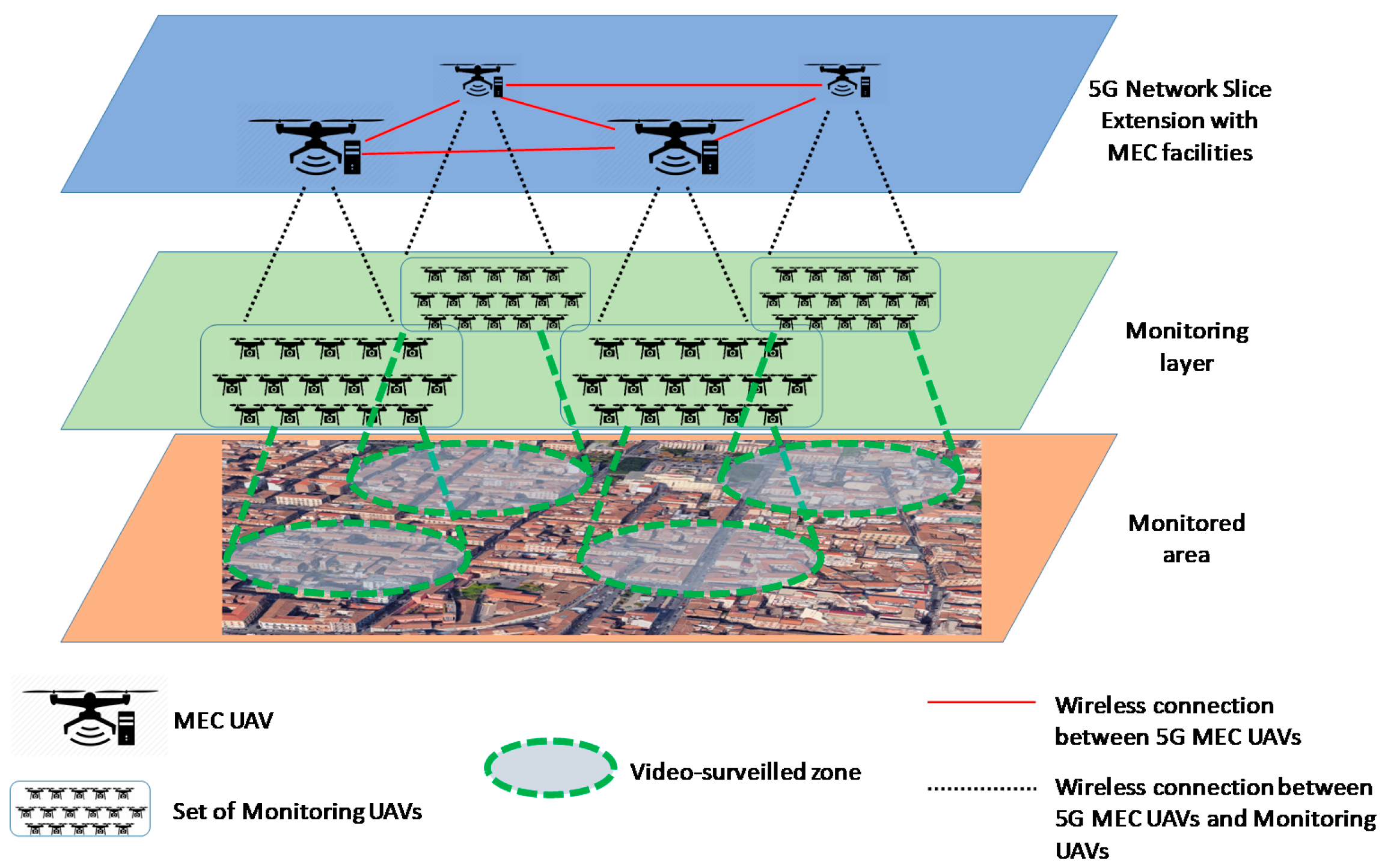
To this purpose, in this paper we propose to extend 5G network slices for video monitoring with a layer of UAVs that are equipped with MEC facilities where running applications to process incoming jobs, as shown in Figure 1. The whole area to be monitored is subdivided in adjacent portions, each monitored by a set of small UAVs (additional sensors can be installed on ground to monitor the same zone). A set of actuators is also installed on the ground to implement actions when some monitoring activities trigger a critical situation. The set of Monitoring UAVs covering a given zone is assigned to one MEC UAV, defined as the primary drone for that zone. The number of Monitoring UAVs assigned to one MEC UAV depends on the load generated by each Monitoring UAV and the load that each MEC UAV, specifically its Microcomputer, is able to manage with acceptable performance. Although, in this paper, for the sake of simplicity, we will assume a constant number of MEC UAVs, it can be varied by the slice Orchestrator when it realizes that the current number of MEC UAVs is either not sufficient or over-dimensioned to manage the current load.
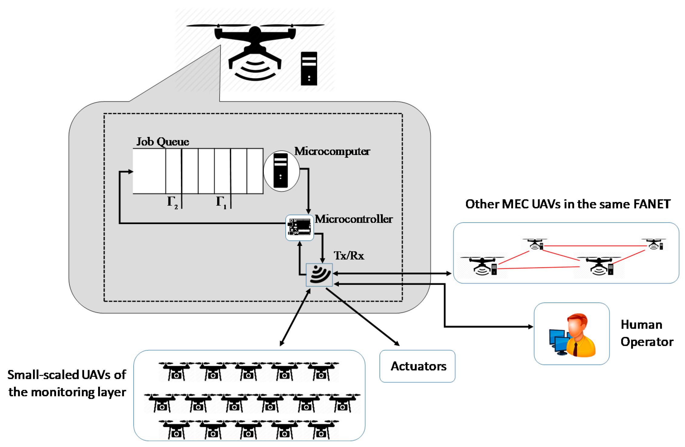
The functional architecture of each MEC UAV is sketched in Figure 2. It is constituted by:
- a Transmit/Receive (Tx/Rx) block that is equipped with multiple antennas for sending and receiving more than one data signal simultaneously over the same radio channel, by exploiting MIMO technologies. Through this block, the MEC UAV receives data flows from all the Monitoring UAVs covering the zone assigned to it, transmits control messages to them, sends action signals to the actuators, and exchanges messages with the other MEC UAVs on the same FANET;
- a Microcontroller board to control processing of the monitoring information coming from the Monitoring UAVs, and decide when sending trigger commands to the actuators in the case of alarm event detection; a reduced flow of information is also sent to a remote human operator to inform him of the most relevant captured data, in order he can take some decisions. In the case his decisions do not arrive in time, the Microcontroller is in charge of autonomously trigger actions on the actuators on the basis of the decisions suggested by the Microcomputer; and,
- a Microcomputer to process jobs offloaded by the Microcontroller. A queue is used to temporary store jobs when the Microcomputer is working on previous jobs.
The whole video monitoring system shown in Figure 1 works as follows. The UAVs at the monitoring layer periodically capture images and send them to the MEC UAV that is assigned to them. The image capturing frequency changes according to feedback messages that the Monitoring UAVs receive either from sensors installed on ground (e.g., motion detection) or the MEC UAV upon processing previous data.
The Tx/Rx block of the MEC UAV sends the received information to the local Microcontroller, which can modify the alarm level of its zone. Transitions between adjacent alarm levels are determined by the information received and processed: the higher the alarm level, the higher the image capturing frequency that is required to the Monitoring UAVs and ground cameras.
Images that are received by Monitoring UAVs and ground cameras and data coming from sensors are combined together by the Microcontroller as jobs to be processed. Let us note that, in order to respect low-latency requirements of sensing-to-actuation time that must be no greater than a given threshold, the Microcontroller cannot offload the processing tasks to a cloud installed on the ground. This is the reason why a Microcomputer is installed on board of the MEC drone to support the Microcontroller in its role of decision support engine to process incoming data and decide, as soon as possible, whether to change the level of alarm and send an “action” message to the actuators installed on the ground.
Each job created by the Microcontroller is enqueued in the Job Queue working with a first-in-first-out (FIFO) policy, where it waits before being processed by the local Microcomputer. Job loss occurs when the queue length exceeds the maximum size K.
Since the waiting time in the job queue is one of the most critical components in the end-to-end latency between video-monitoring data generation devices and actuators, we introduce a mutual-help policy among MEC UAVs in order to decrease its value together with the job loss rate. This policy will be described in Section 3.
3. Mutual Help Policy among MEC UAVs
In this section, we define a cooperation policy among MEC UAVs, with the aim of reducing both the mean value of the duration of the permanence for a job in the system, , and the job loss rate in the job queue, PJL.
To this end, we introduce two thresholds on the queue length, and , with , where is the maximum size of the job queue. The two thresholds are used as explained below.
When the queue length exceeds , meaning that the local Microcomputer is not able to sustain the current job load, support of an additional MEC UAV, assuming the role of secondary drone, is required. The choice of the secondary drone is done according to the queue state of the drones flying at a distance not greater than a given value δ. The value of the distance δ is a system parameter that depends on both the maximum distance that the TX/RX module installed on MEC drones can cover and the distance between drones in the FANET topology. The drone that is chosen as secondary drone is the one with the lowest queue length among the ones that are in proximity (i.e., with a distance not greater than δ), which are not yet secondary drones, and that are not helped by any other drone to manage the zone where they are the primary drone.
If no drones are available to assume the role of secondary drone (because no MEC UAV within a distance of δ matches the above requirements), then the primary drone will issue new help requests at each new job arrival or service event, or at a timeout event.
On the other hand, if the queue length decreases to a value that is less than the second threshold, , the secondary drone will not be more needed, and the zone is again managed by only the primary drone.
The phase of the secondary drone selection starts with a help request that is issued in broadcast by the primary drone to the drones in proximity. They answer by sending their status to the requesting primary drone. The latter assigns the role of secondary drone on the basis of the received information, and it sends a direct communication to the selected one about its choice. It also notifies UAVs of the monitoring layer in order that they can split their data flows to the two drones currently monitoring the same area. A similar signaling information exchange occurs when the secondary drone ends its helping role.
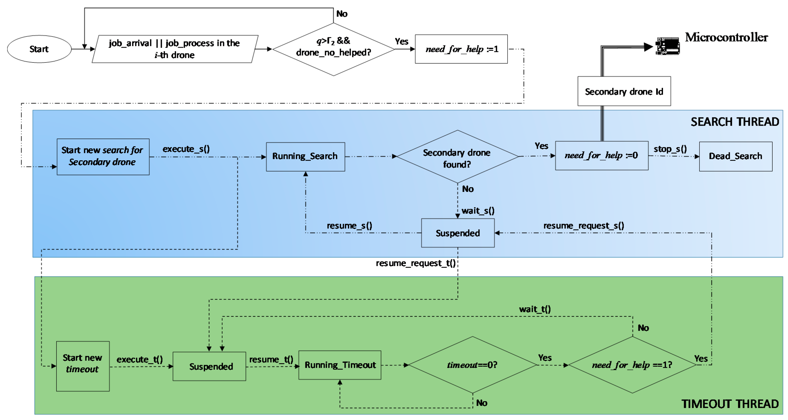
Figure 3 shows how the search algorithm for a secondary drone works, carried out by the generic i-th drone. We consider the two possible events that determine a queue length variation, i.e., the case when a job arrives to the i-th drone or it is served by its Microcomputer. If the queue state of this drone, q, is greater than , and the drone is not still helped, the need_for_help variable is set to 1 and a new Search thread is instantiated.
As soon as the <execute_s()> method is invoked in the Search thread, the Search thread enters the Running_Search state and starts to execute the code of the Algorithm 1. At the same time, another thread, the Timeout thread, is also instantiated, with the aim of repeating this procedure periodically until a secondary drone is not found. This last thread enters the Suspended state, waiting for receiving a <resume_request_t()> message.
| Algorithm 1. Running Search execution code | |
| 1 | Begin |
| 2 | Send a help_request message in broadcast. Only UAVs within a distance δ receive it |
| 3 | Receive queue-state from all the UAVs in proximity that are neither helping other UAVs nor helped |
| 4 | if some UAV is available |
| 5 | then Secondary drone Id ≔ drone Id of the drone with the smallest queue |
| 6 | else the considered UAV remains alone until next invocation of this algorithm |
| 7 | Secondary drone Id ≔ null |
| 8 | end |
| 9 | Return Secondary drone Id |
| 10 | End |
If the secondary drone search procedure, at its end, has been able to find a secondary drone, then the variable need_for_help is set to 0, the Id of the UAV chosen as secondary drone is sent to the Microcontroller, and the Search thread receives the <stop_s()> command to die.
On the contrary, if no secondary drone has been found, then the <wait_s()> method is invoked, the Search thread enters the Suspended state, and a <resume_request_t()> message is sent to the Timeout thread. This one leaves the Suspended state, invokes the <resume_t()> method and enters the Running_Timeout state where a countdown begins by decreasing the timeout variable. At a time when timeout reaches the value 0, if need_for_help is still equal to 1, the <resume_request_s()> method allows the Search thread to exit from the Suspended state and, after invoking <resume_s()>, returns to the Running_Search() state. Instead, if need_for_help is equal to 0, because in the meanwhile the queue of the drone has reached a value below the threshold, the Timeout thread enters the Suspended state and waits for next actions.
4. Performance Metrics
In order to evaluate the behavior of the system and compare it with a state-of-art system, we define some performance metrics.
The first two metrics, regarding application level Quality of Service (QoS), are the mean response time and the job loss rate. On the other hand, we introduce three more metrics regarding the behavior analysis of the proposed framework; they can be used to understand how the system is working, so allowing a fine tuning of the main parameters with the aim of improving its performance. They are the no-helped probability, the mean duration of no-helped periods, and the percentage of time that is devoted to help another UAV.
The mean response time is defined as the mean value of the duration of the permanence for a job in the system, that is:
where is the mean time of permanence in the queue, while is the mean value of the time that is needed by a job to be processed in the Microcomputer and is an input of the problem. The variable can be derived through the Little law as an average of the ratio between the expected value of the number of jobs in the queue of each drone u, , and the expected value of the arrival rate to that drone, , that is:
If we indicate how much time the job queue of the UAV u stays with a job queue length of jobs in a period of duration t as , and the cumulative number of arrivals in the same interval as , from Equation (2), we have:
The job loss rate, as the previous metric, is averaged over all the UAVs, and, for each UAV u, it is calculated as the ratio between the number of jobs that are lost for queue overflow in a period with a duration of t, , and the total number of jobs created by the monitoring UAVs assigned to u in the same period, . So, we have:
The third parameter, called the no-helped probability, is averaged over all the UAVs and, for each of them, it is defined as the ratio between the cumulative time duration calculated until the time instance t of the period in which the UAV u, although with a job queue length that is higher than , is not helped by a secondary drone because it is not available, and the overall time duration, , of the period, in the same interval, that the considered UAV has had a job queue length higher than :
The fourth parameter is the mean duration of no-helped periods, defined as follows:
where is the number of no-helped occurrences when the UAV u needs to be helped (i.e., its queue is over ) in t seconds.
Finally, the last parameter represents the percentage of time devoted to help another UAV. It can be calculated as the cumulative time that is spent by each UAV in helping some other UAV in a period of duration t, , normalized over the time duration t, and averaged for all of the UAVs in the system, that is:
5. Use Case
In this section, we consider a use case to evaluate performance of the proposed system, and discuss the choice of some system parameters in order to respect requirements in terms of latency for provisioning computing service and job loss ratio. The analysis will be carried out as a function of the job queue size, K, since this parameter is a determinant in the trade-off between the two above QoS parameters: the higher K, the lower the job loss rate, but the higher the system response time. Performance analysis has been carried out with an event-based Matlab simulator. Simulation setup will be described in Section 5.1, while Section 5.2 presents some numerical results.
5.1. Simulation Setup
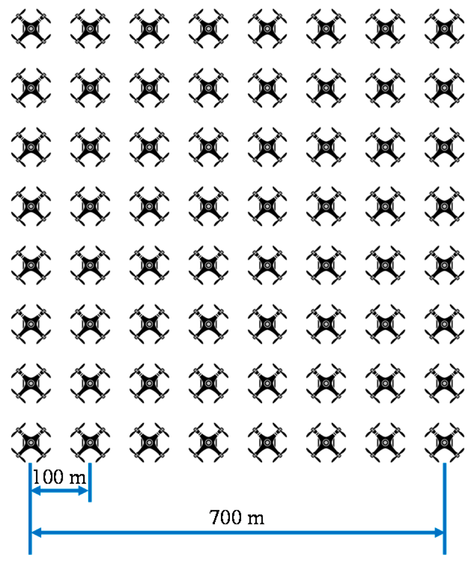
We consider a 5G slice extension with N = 64 MEC UAVs, organized in a FANET with a regular grid topology, as shown in Figure 4. In order to evaluate the gain that is achieved by using the proposed Mutual Help Policy among MEC UAVs, we will consider the following two different configurations:
- “w/help”: each UAV has a horizontal coverage range of δ = 1 km, and therefore it is able to cooperate with all the other UAVs in the platform; and,
- “w/o help”: each UAV has a horizontal coverage range of δ = 70 m, and therefore each zone is covered by the primary drone only. This case is equivalent to the state-of-art case, in which the strategy of “mutual help among MEC UAVs” proposed in this paper is not applied.
We assume two levels of alarm for each monitored zone, and an exponentially distributed job arrival rate with a mean value λ, depending on the current alarm level. More specifically, when considering that each MEC UAV receives jobs from all the monitoring devices of the zone assigned to it, we have considered a mean arrival rate during no-alarm state of λL = 1 arrival/ms, while the arrival rate during an alarm state is increased with a factor of 15, that is, λH = 15 arrivals/ms. As concerns the Microprocessor unit on board of each MEC UAV, we have assumed that it is able to process one job in TJ = 769 μs, that is, it has a job processing rate of μ = 13 jobs/ms. Moreover, we will model the alarm-level transitions with a two-state Markov chain that is characterized by the following transition rate matrix:
In the numerical analysis, we will vary the job queue size, K, in the range [100, 1000]. The two thresholds and , after a huge number of simulations, have been decided, as follows:
Every set of experiments was repeated 30 times with different random seeds, and the duration of simulation has been automatically chosen in such a way that the 95% confidence interval is less than 1% of the average results. The seeds, which affected all of the random parameters in the experiments, were taken from the default pseudo-random generator of Matlab.
5.2. Numerical Results
In this section, we present numerical results achieved by a Matlab event-based simulator with the setup described in the previous section.
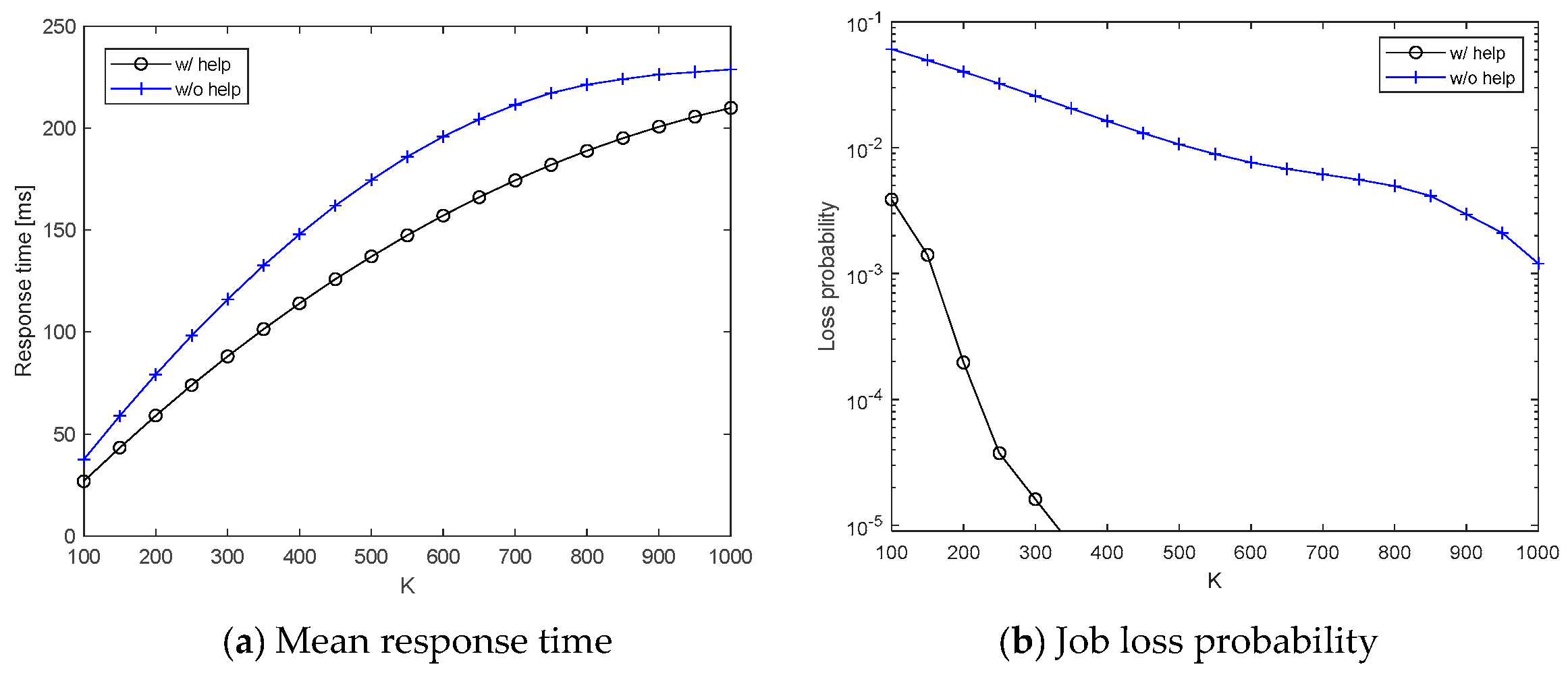
Figure 5 plots the two application-level QoS parameters and against the job queue size K. In both Figure 5a,b, we can appreciate the gain that is achieved by applying the Mutual Help Policy among MEC UAVs. For example, we can notice that, for job buffer size of 300, the job loss probability is around 1 × 10⁻⁵ if the Mutual Help Policy is applied, with a mean response time of 88 ms. If a higher response time is accepted, then job losses can be further reduced by increasing the buffer size.
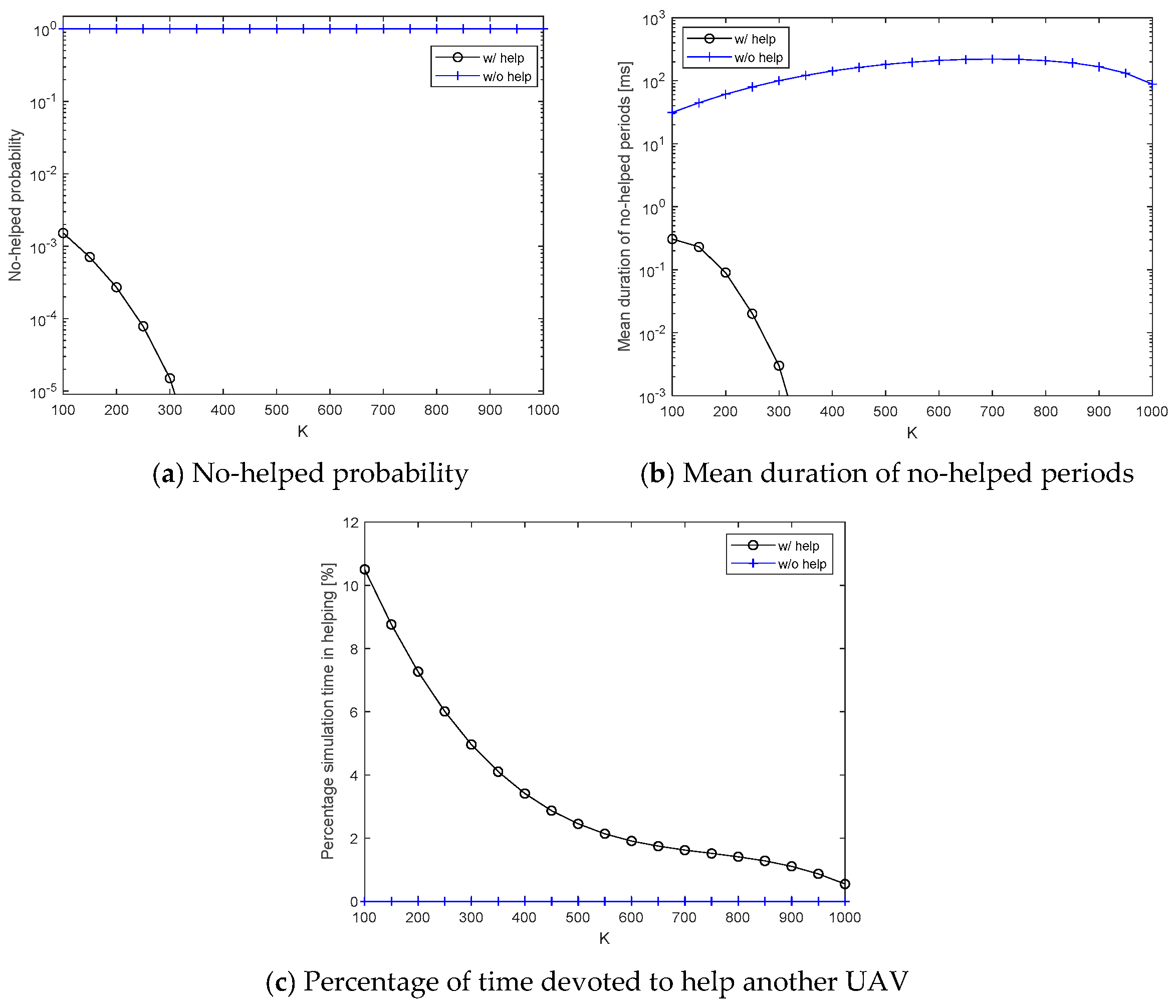
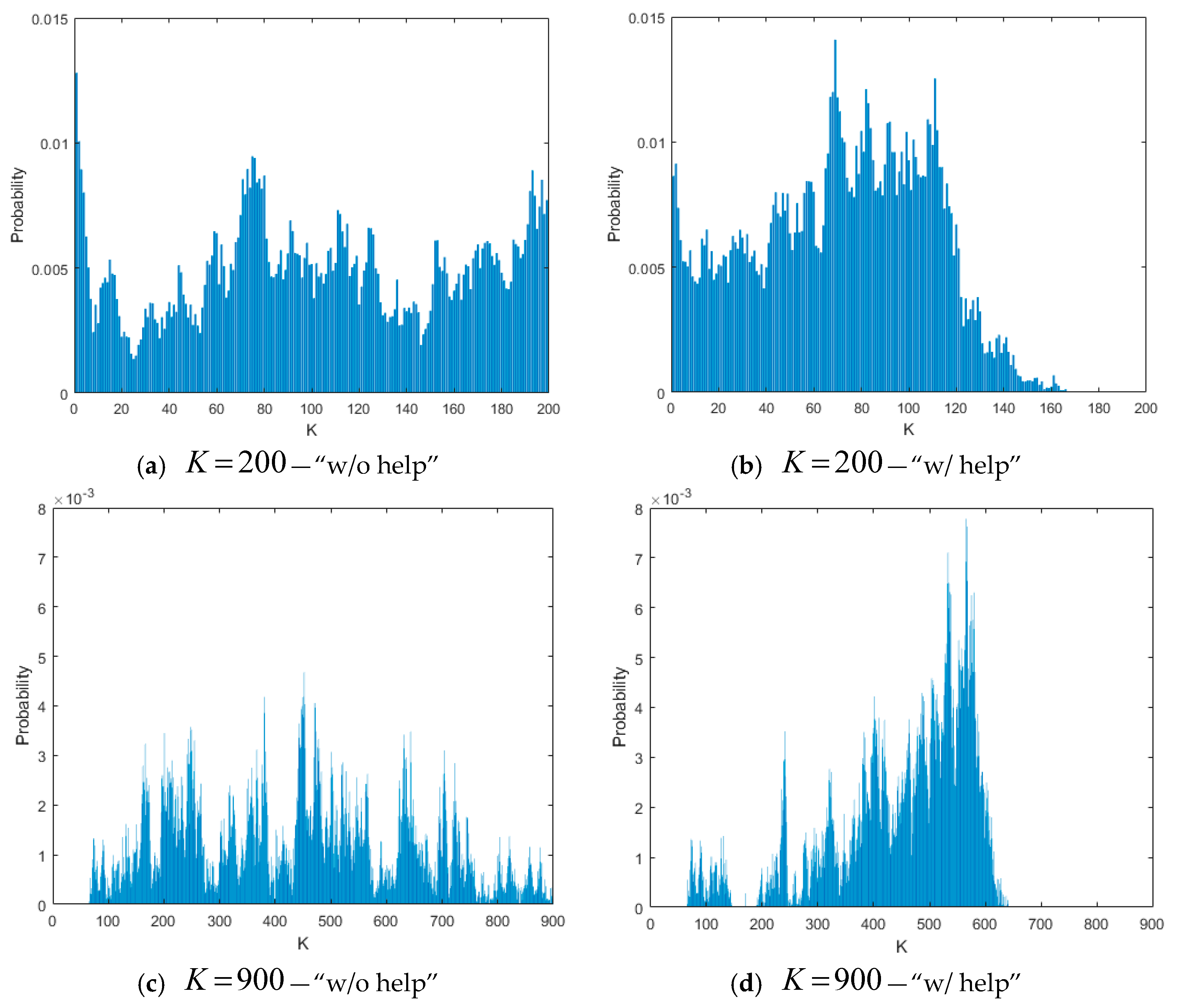
Figure 6 presents the three performance parameters defined in Equations (5)–(7) for an internal behavior analysis of the proposed framework. Of course, the curves relating to the “w/o help case” in Figure 6a,c are trivial, but they have been reported here for the sake of completeness. In order to better understand the curves in Figure 6, in Figure 7 we have shown the normalized histograms of the job queue length for K = 200 and K = 900, measured for one of the drones in the FANET, and for both the configurations “w/o help” and “w/help”.
As we can notice in Figure 7, if the Mutual Help Policy is not applied, the queue length spans in the whole range between 0 and K, also causing some losses for K = 200. On the contrary, application of the Mutual Help Policy allows for maintaining the queue rarely over 160 jobs for K = 200 and 600 jobs for K = 900, so strongly reducing losses. For higher values of K, and consequently of the thresholds and , the queue length rarely exceeds , and therefore the gain of the Mutual Help Policy is low again. This is the reason why in Figure 6a,b the curves for the “w/help” case are not present for high values of K. Instead, for low values of K, the curves are present and decrease because situations that are characterized by queue lengths higher than are less frequent for K increasing, and so the secondary drone search is less invoked, and therefore more UAVs are available to help the few ones that request some help.
The curve of the “w/o help” case in Figure 6b testifies two different behaviors of the system: it increases up to K = 650, because, for low values of K and K increasing, the loss probability decreases and the whole number of packets managed by the MEC platform at the same time increases (making the whole platform with a higher load), so increasing the time to find a secondary UAV. Instead, the right part of the curve is decreasing because the probability that the queue length is greater than decreases, and therefore the system appears to be less loaded. For the above reasons, the curve in Figure 6c for the “w/help” case is decreasing in the whole range of K.
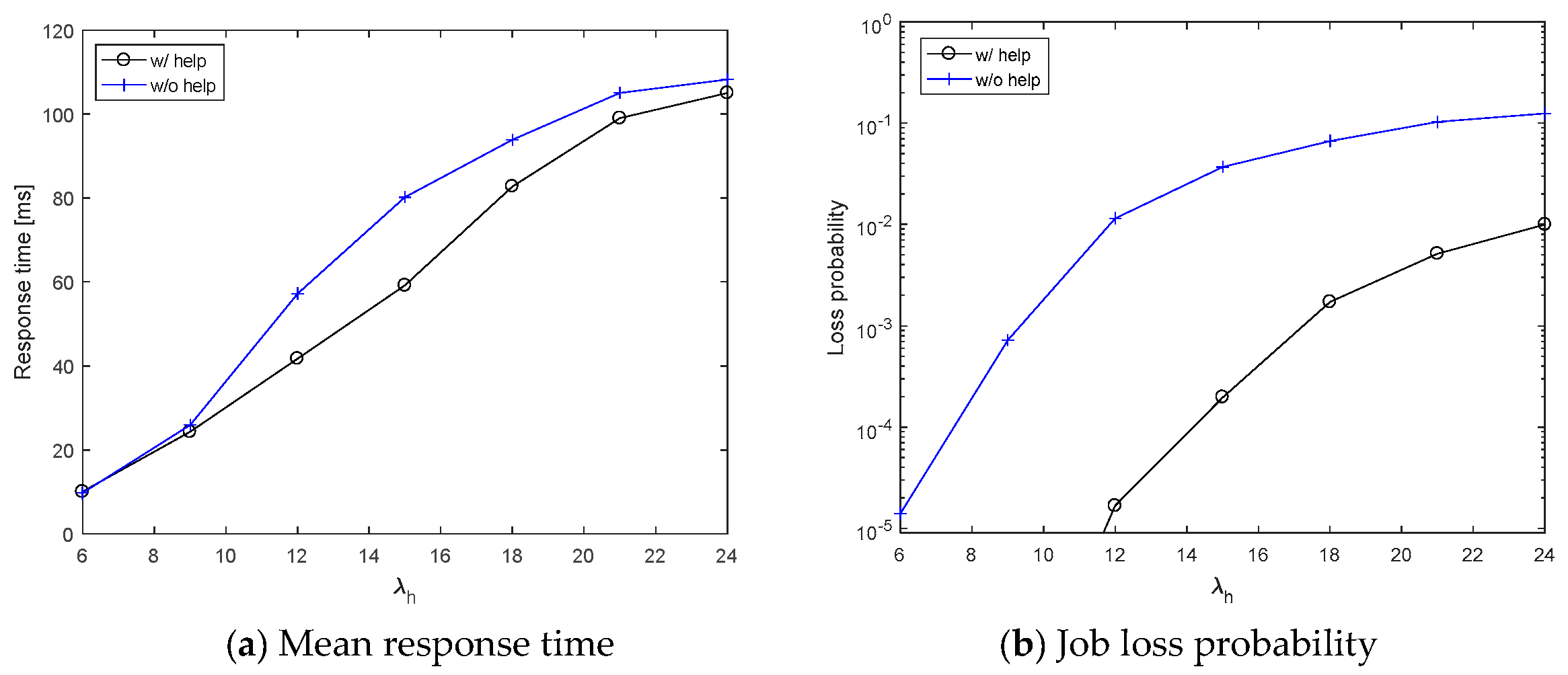
Finally, another important analysis is the impact of the arrival rate parameter to the overall system performance. To this purpose, in Figure 8 we reported the mean response time and the job loss probability as a function of the arrival rate during an alarm state, ranging in the interval [6,24] arrival/ms, while we have kept the arrival rate during the no-alarm state constant and equal to 1 arrival/ms. We can notice that, although a gap between the “w/help” and the “wo/help” remains in the job loss probability (see Figure 8b), the mean response time that is shown in Figure 8a is improved by the Mutual Help Policy for intermediate values of the arrival rate since. In fact, for low values of λH, the platform is underloaded, and therefore MEC UAVs do not need any help, while, for high values of λH, the platform is so overloaded that it is unlikely to find MEC UAVs available for helping.
6. Conclusions and Future Work
This paper has considered the problem of supporting a video-surveillance system that is realized with low-altitude small UAVs, sensors, and actuators requiring LOS communications towards facilities of edge computing to allow high-speed transmission of high-volume data flows, such as live video streams. The proposed solution is an extension of a 5G network slice with a FANET constituted by UAVs with MEC facilities (also referred to as MEC UAVs), where monitoring devices can offload the elaboration of video and data flows that they produce. A policy of mutual help among MEC UAVs has been also defined to reduce response delays mainly due to the queue of jobs waiting to be processed on board of MEC UAVs, and increase reliability. A use case has been proposed to evaluate the proposed platform, and obtaining some insights for system design.
The paper does not consider the limited battery duration of MEC UAVs. Although some kinds of UAVs, as, for example, fixed-wing aircrafts [23,24], are able to fly for some hours, the problem of MEC UAV unavailability for battery charging is one of the main issues for UAV missions today. In fact, some solutions can strongly reduce UAV unavailability, for example, substituting a MEC UAV with low battery charge with a fully-charged one, or providing a charged battery to a MEC UAV to substitute its low-charged one. On the contrary, if a MEC UAV with low-charged batteries has to land to be charged, this UAV leaves its role for a longer time, causing service degradation. Therefore, according to the adopted solution, the Mutual Help Policy proposed in this paper should be extended with a reconfigurable FANET network, and this will be considered as a future work.
Another future work regards the definition of a Markov-based analytical model to allow for studying of system performance in cases that are not analyzable by simulation.
Author Contributions
Conceptualization, C.G. and G.S.; Methodology, G.S.; Software, C.G.; Validation, C.G.; Formal Analysis, G.S.; Investigation, C.G.; Resources, G.S.; Data Curation, C.G.; Writing-Original Draft Preparation, G.S.; Writing-Review & Editing, G.S. and C.G.; Visualization, G.S. and C.G.; Supervision, G.S.; Project Administration, G.S.; Funding Acquisition, G.S.
Funding
This research received no external funding
Conflicts of Interest
The authors declare no conflict of interest.
References
- Martinel, N.; Micheloni, C.; Piciarelli, C. Pre-Emptive Camera Activation for Video Surveillance HCI. In Proceedings of the International Conference on Image Analysis and Processing, Ravenna, Italy, 14–16 September 2011; pp. 189–198. [Google Scholar]
- Remagnino, P.; Velastin, S.A.; Foresti, G.L.; Trivedi, M. Novel Concepts and Challenges for the Next Generation of Video Surveillance Systems. Mach. Vis. Appl. 2007, 18, 135–137. [Google Scholar] [CrossRef]
- Mosteo, A.R.; Montano, L.; Lagoudakis, M.G. Guaranteed-Performance Multi-Robot Routing under Limited Communication Range. In Distributed Autonomous Robotic Systems; Springer: Berlin/Heidelberg, Germany, 2009; pp. 491–502. [Google Scholar]
- Fu, C.; Duan, R.; Kircali, D.; Kayacan, E. Onboard Robust Visual Tracking for UAVS Using a Reliable Global-Local Object Model. Sensors 2016, 16, 1406. [Google Scholar] [CrossRef] [PubMed]
- Zhang, M.; Liu, H.H.T. Cooperative Tracking a Moving Target Using Multiple Fixed-Wing UAVS. J. Intell. Robot. Syst. 2016, 81, 505–529. [Google Scholar] [CrossRef]
- Khan, A.; Yanmaz, E.; Rinner, B. Information exchange and decision making in micro aerial vehicle networks for cooperative search. IEEE Trans. Control Netw. Syst. 2015, 2, 335–347. [Google Scholar] [CrossRef]
- D’Urso, F.; Grasso, C.; Santoro, C.; Santoro, F.F.; Schembra, G. The Tactile Internet for the flight control of UAV flocks. In Proceedings of the 2018 4th IEEE Conference on Network Softwarization and Workshops (NetSoft), Montreal, QC, Canada, 25–29 June 2018; pp. 470–475. [Google Scholar]
- Rametta, C.; Schembra, G. Designing a softwarized network deployed on a fleet of drones for rural zone monitoring. Future Internet 2017, 9, 8. [Google Scholar] [CrossRef]
- Felizardo, L.F.; Mota, R.L.; Shiguemori, E.H.; Neves, M.T.; Ramos, A.B.; Mora-Camino, F. Using ANN and UAV for Terrain Surveillance. In Proceedings of the 13th International Conference on Hybrid Intelligent Systems (HIS 2013), Gammarth, Tunisia, 4–6 December 2013; pp. 1–5. [Google Scholar]
- Kreutz, D.; Ramos, F.M.V.; Veríssimo, P.E.; Rothenberg, C.E.; Azodolmolky, S.; Uhlig, S. Software-Defined Networking: A Comprehensive Survey. Proc. IEEE 2015, 103, 14–76. [Google Scholar] [CrossRef] [Green Version]
- Herrera, J.d.J.G.; Vega, J.F.B. Network Functions Virtualization: A Survey. IEEE Lat. Am. Trans. 2016, 14, 983–997. [Google Scholar] [CrossRef]
- Taleb, T.; Samdanis, K.; Mada, B.; Flinck, H.; Dutta, S.; Sabella, D. On Multi-Access Edge Computing: A Survey of the Emerging 5G Network Edge Cloud Architecture and Orchestration. IEEE Commun. Surv. Tutor. 2017, 19, 1657–1681. [Google Scholar] [CrossRef]
- Mach, P.; Becvar, Z. Mobile Edge Computing: A Survey on Architecture and Computation Offloading. IEEE Commun. Surv. Tutor. 2017, 19, 1628–1656. [Google Scholar] [CrossRef] [Green Version]
- Manzalini, A.; Saracco, R. Software Networks at the Edge: A Shift of Paradigm. In Proceedings of the 2013 IEEE SDN for Future Networks and Services (SDN4FNS), Trento, Italy, 11–13 November 2013; pp. 1–6. [Google Scholar]
- Lombardo, A.; Manzalini, A.; Schembra, G.; Faraci, G.; Rametta, C.; Riccobene, V. An open framework to enable NetFATE (Network Functions at the edge). In Proceedings of the 2015 1st IEEE Conference on Network Softwarization (NetSoft), London, UK, 13–17 April 2015; pp. 1–6. [Google Scholar]
- Simsek, A.; Aijaz, A.; Dohler, M.; Sachs, J.; Fettweis, G. The 5G-Enabled Tactile Internet: Applications, requirements, and architecture. In Proceedings of the 2016 IEEE Wireless Communications and Networking Conference, Doha, Qatar, 3–6 April 2016; pp. 1–6. [Google Scholar]
- Fettweis, G.P. The Tactile Internet: Applications and Challenges. IEEE Veh. Technol. Mag. 2014, 9, 64–70. [Google Scholar] [CrossRef]
- Grasso, C.; Schembra, G. Design of a UAV-Based Videosurveillance System with Tactile Internet Constraints in a 5G Ecosystem. In Proceedings of the 2018 4th IEEE Conference on Network Softwarization and Workshops (NetSoft), Montreal, QC, Canada, 25–29 June 2018; pp. 449–455. [Google Scholar]
- Foukas, X.; Patounas, G.; Elmokashfi, A.; Marina, M.K. Network Slicing in 5G: Survey and Challenges. IEEE Commun. Mag. 2017, 55, 94–100. [Google Scholar] [CrossRef] [Green Version]
- Ordonez-Lucena, J.; Ameigeiras, P.; Lopez, D.; Ramos-Munoz, J.J.; Lorca, J.; Folgueira, J. Network Slicing for 5G with SDN/NFV: Concepts, Architectures, and Challenges. IEEE Commun. Mag. 2017, 55, 80–87. [Google Scholar] [CrossRef] [Green Version]
- Rosati, S.; Krużelecki, K.; Heitz, G.; Floreano, D.; Rimoldi, B. Dynamic Routing for Flying Ad Hoc Networks. IEEE Trans. Veh. Technol. 2016, 65, 1690–1700. [Google Scholar] [CrossRef]
- The Tactile Internet, ITU-T Technology Watch Report. August 2014. Available online: https://www.itu.int/oth/T2301000023/en (accessed on 1 November 2018).
- Gunarathna, J.k.; Munasinghe, R. Development of a Quad-rotor Fixed-wing Hybrid Unmanned Aerial Vehicle. In Proceedings of the 2018 Moratuwa Engineering Research Conference (MERCon), Moratuwa, Sri Lanka, 30 May–1 June 2018; pp. 72–77. [Google Scholar]
- Paredes, J.A.; Saito, C.; Abarca, M.; Cuellar, F. Study of effects of high-altitude environments on multicopter and fixed-wing UAVs’ energy consumption and flight time. In Proceedings of the 2017 13th IEEE Conference on Automation Science and Engineering (CASE), Xi’an, China, 20–23 August 2017; pp. 1645–1650. [Google Scholar]
Figure 1.
Reference System and Proposed Architecture.

Figure 2.
Functional Architecture of a multi-access Edge Computing unmanned aerial vehicles (MEC UAV).
Figure 2.
Functional Architecture of a multi-access Edge Computing unmanned aerial vehicles (MEC UAV).

Figure 3.
Mutual Help Policy implementation algorithm.

Figure 4.
Flying Ad-hoc NETwork (FANET) topology used in the use case.

Figure 5.
Application-level Quality of Service (QoS) parameters.

Figure 6.
Performance parameters for a behavior analysis of the proposed framework.

Figure 7.
Normalized histograms of the job queue length.

Figure 8.
Dependence of application-level QoS parameters on the job arrival rate during alarm states.
Figure 8.
Dependence of application-level QoS parameters on the job arrival rate during alarm states.

© 2019 by the authors. Licensee MDPI, Basel, Switzerland. This article is an open access article distributed under the terms and conditions of the Creative Commons Attribution (CC BY) license (http://creativecommons.org/licenses/by/4.0/).
Share and Cite
MDPI and ACS Style
Grasso, C.; Schembra, G. A Fleet of MEC UAVs to Extend a 5G Network Slice for Video Monitoring with Low-Latency Constraints. J. Sens. Actuator Netw. 2019, 8, 3. https://0-doi-org.brum.beds.ac.uk/10.3390/jsan8010003
AMA Style
Grasso C, Schembra G. A Fleet of MEC UAVs to Extend a 5G Network Slice for Video Monitoring with Low-Latency Constraints. Journal of Sensor and Actuator Networks. 2019; 8(1):3. https://0-doi-org.brum.beds.ac.uk/10.3390/jsan8010003
Chicago/Turabian StyleGrasso, Christian, and Giovanni Schembra. 2019. "A Fleet of MEC UAVs to Extend a 5G Network Slice for Video Monitoring with Low-Latency Constraints" Journal of Sensor and Actuator Networks 8, no. 1: 3. https://0-doi-org.brum.beds.ac.uk/10.3390/jsan8010003
Note that from the first issue of 2016, this journal uses article numbers instead of page numbers. See further details here.