
A Systematic Robust Design Method to Reduce Products’ Environmental Impact Variations


Department of Management, Information and Production Engineering, University of Bergamo, via Marcon 5, 24044 Dalmine, BG, Italy
Knowledge 2022, 2(2), 266-285; https://0-doi-org.brum.beds.ac.uk/10.3390/knowledge2020016
Submission received: 21 March 2022
/
Revised: 22 April 2022
/
Accepted: 12 May 2022
/
Published: 17 May 2022
Abstract
:Reducing the environmental impact of a device arising from unexpected failures should be an environmental goal. However, this problem can be difficult to tackle, especially due to the limitations of the traditional eco-design methods, which are more used to reduce the baseline impacts. This study proposes a novel method to overcome this limitation, working at the intersection of conceptual design, robust design, and eco-assessment. Based on the inquiry-based approach, the method consists of 52 questions, systematically organised on 4 hierarchical levels dedicated to the formulation of the initial environmental problem, the definition of the design goal, and the strategy and the selection of the methods, tools, and solutions to be applied. The method was applied in two real case studies about an adsorption air dryer and a medium-voltage circuit breaker by providing different solutions, where the most promising one was able to avoid the environmental impact variations up to 2% of the total impacts of the device. The method could be a starting point to build a design theory that is dedicated to this sector, still largely unexplored, while this vocation towards conceptual design is an appeal for a contamination of the more routine fields of robust and eco-design on the educational, application, and research levels.
1. Introduction
Most eco-design approaches, methods, and tools aim to reduce the environmental impacts of a device or a process, while only few explicitly state that they reduce the variability of the impacts (e.g., [1,2,3]). However, if one considers the latter as a positive consequence of the interventions aimed at making the phases of the device’s life cycle more controllable, stable, and repeatable, then the list of supporting approaches becomes wider, including, for example, FMEA (Failure Modes and Effects Analysis), Six Sigma, and Robust design. However, there is no unambiguous definition in the literature, much less a dedicated ontology to describe precisely what variation in an environmental impact might be, although this is not a secondary problem, as evidenced by the environmental damage resulting from accidents (e.g., [4,5]).
From the contributions in the literature which worked in this area (see Section 2), it is quite clear that a variation in the impacts could be a direct consequence on the environment of an event that is not normally foreseeable, such as an unexpected failure, a natural disaster, or a user misuse. For this reason, the variation in the impacts should not be confused with their uncertainty, expressed by an eco-assessment study, which is instead the quantitative degree of a lack of precision about information not known for sure [6].
However, despite the positive aspects, these contributions still have some limitations.
- The lack of a unique approach to address all the different types of problems related to the variability of environmental impacts, which can lead the designer to only use the methods they know best, even though they are not the most suitable, or to select only the better supported problems.
- The high application efforts, especially of the more structured approaches such as FMEA, which require extensive analysis on all components of the considered device.
- The lack of eco-assessments in the problems to be solved and in the solutions identified in most of the supporting methods, which risks making the least sustainable solutions prevail during decision making.
Compared to the state-of-the-art contributions, the method proposed in this paper presents some novelties to overcome their limitations. It introduces a unique design framework to address all the major problems on which variations in environmental impacts depend, guiding the designer in selecting the most appropriate method from among the state-of-the-art ones, after a thorough investigation of the problem.
This phase has been structured through a series of questions, in series and in parallel, at first more generic and then more precise, according to the logic of the inquiry-based learning method [7]. Their function is to stimulate the designer to reformulate the initial problem several times, identifying goals and strategies to solve it. Only the last questions suggest the methods to be used (i.e., conceptual and robust design theories and methods), but the answers to the previous questions can be exploited to select the most appropriate in relation to the problem to be solved and suggest their more focused and streamlined use.
In addition, both eco-assessment and conceptual design theories play key roles in the method. The first one is useful for identifying and quantifying the impacts of the initial problems in a rigorous manner, showing the primary ones to work on, and for evaluating the benefits of the obtained solutions during decision making, while the conceptual design theories constitute the ontological and content basis that has been selected to formulate the questions used to define the goals and strategies. This is because the idea of not disavowing or distorting design theories is fully justifiable by analysis of the state of the art. Guiding their use, reasoning more deeply and in a structured way on problems, goals, and strategies, rather than looking for immediate solutions, can instead enlarge their number and quality, as empirically demonstrated for a long time (e.g., [8]).
On the other hand, the issue of asking questions rather than providing answers is highly debated, especially at the educational level, and has several supporters. This approach is well suited to stimulate problem reformulation. While their generality, despite the introduction of ontological content, is almost necessary to manage the marked heterogeneity of the problems, methods, and solutions related to the variability of environmental impacts.
The initial assumption on which this work is based is that the problem of reducing variation in environmental impacts depends on aspects that are too heterogeneous to be addressed by a methodology that is too rigid and monothematic. In other words, comparable environmental benefits could be found in solutions that work on many different aspects and were derived from different design paths. If this were the case, the perspective of work that a designer would have to adapt when working at this stage, using the proposed method, would be changed in favour of greater freedom of maneuver and attention to creativity as in conceptual design. Finally, the obtained results could also be interesting for research, stimulating a contamination between the different fields of conceptual design theories, robust design, and eco-assessment.
2. Literature Review
Different methods anticipate in part the objectives and the content of the proposed method. The reduction of the environmental impacts of a product, also considering those not foreseen, which emerge from failures and malfunctions, can be addressed not only by applying the methods having an environmental objective, but also by other more generic design and robust design methods. This is because a good design leads to a product characterised by stable operation over time, a life cycle controlled and aligned with the design specifications [9]. However, the choice of the most appropriate supporting method according to the type of product and the type of environmental impact, even if not foreseen, to be avoided is anything but obvious and not supported by studies in the literature.
First of all, a shared classification of the different causes of variation in the environmental impacts is lacking. Different methods, based on FMEA and its combinations with LCA and Lean Six Sigma, consider only a few causes, mainly related to variations in the conditions of use of the product. This is because the FMEA is mainly used to analyse the requirements related to the functioning of the product, their variations and the effects of these variations (e.g., [10,11]).
Other approaches based on FTA (Fault Tree Analysis) and AHP (Analytical Hierarchy Process) are more rigorous than those based on FMEA in determining and describing the environmental effects deriving from variations in the standard operation of a product. This is because, according to the authors who developed them, such methods allow a better and more rigorous integration with the standard indices of environmental impact [12]. Furthermore, these approaches better structure the identification phase of environmental effects than the FMEA, providing practical suggestions about the approaches and tools to be used, such as root cause analysis [12]. In any case, in both the approaches, the analysis of the environmental effects deriving from user’s misuses is missing or barely sketched. This is because the determination of user’s misuses is lacking, in turn because the modelling of the relationships between the user and the product is lacking [11].
Some existing methods, on the other hand, are more complete, both in supporting the mapping of faults and malfunctions and in determining the environmental effects and quantifying them, proposing indications and guidelines to support them. However, both these indications are always too specific in relation to very restricted application areas, and the case studies provided exemplify the operation of these methods only within these specific application areas and with restricted boundary conditions (e.g., [13]).
There are also other approaches, e.g., the Resilience theory [14], clearly more polyvalent in approaching different types of products, albeit supporting the designer at a more qualitative level. However, for this reason, the indications provided by these approaches to identify, model, and quantify the environmental impacts associated with possible failures are rather generic and approximate, requiring skill and application from the designer [15].
Robust design can be considered a more structured and quantitative variant of Resilient theory, which, for these qualities, has been more successful in design (e.g., [16]). Its main strengths are its ability to analyze many aspects throughout the entire lifecycle of the device and the use and integration of tested and established analysis procedures. However, robust design has also been criticised for focusing primarily on the manufacturing and use phases and having a certain difficulty at the application level, especially perceived by industry, due to its lack of pragmatism [17]. Only few contributions tried to overcome the limitations of robust design in this field, integrating some design methods to provide a more structured approach (e.g., [18]). However, their small number and the excessive specificity of the tested application fields do not allow for a general judgment of validity to be made.
Finally, there are approaches specifically dedicated to hypothesize the user’s misuses of the product and more rarely even to assess their harmful effects on the environment. The first part was properly deepened in dedicated design theories that classified users’ misuses in a very broad and in-depth manner, by providing comprehensive support to the designer in order to improve the structure (through the introduction of the affordances) of the product to eliminate the possible misuses or their effect when they occur (e.g., [19,20]). However, the attention that these design approaches pay to environmental sustainability is rather marginal, often treated implicitly, superficially, or totally neglected, and for these reasons, it is difficult for the designer to ensure that this requirement is also met [21]. Studies working at the intersection of designing for avoiding misuses and eco-design (e.g., [22,23]) aim to ensure that the user uses the technical system in the greenest way possible. Consequently, as they are more interested in suggesting eco-sustainable behaviour than in avoiding all possible misuse by the user, their consideration of misuse is rather limited compared to more general design approaches.
3. Methods
The state-of-the-art analysis of the proposals does not reveal problems with the current methods such that they need to be replaced, but reveal their limited pragmatism in addressing the problem of reducing the variability in environmental impacts across the board.
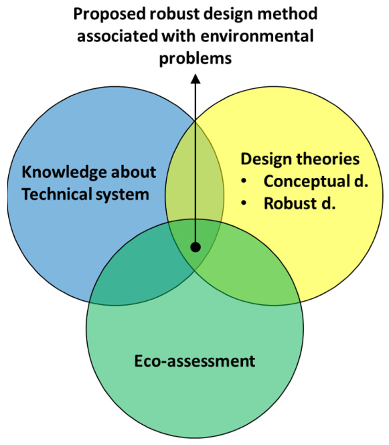
For this reason, we have directed our efforts towards the definition of a systematic method that can serve as a framework to explain how to select and use design theories, knowledge of the device (from now on called “Technical System” to adapt to the ontology adopted for the method) and its anomalies, and eco-assessment to reduce the variability of environmental impacts (see Figure 1).
The backbone of the proposed method is the phase of reformulating the initial problem so that it is more congenial to being addressed. The same thing happens in conceptual design theories, for the definition of a new device, e.g., SAPB (Systematic Approach of Pahl and Beitz) [24], FBS (Function Behaviour Structure) [25], and for inventive problem solving, e.g., TRIZ (Russian acronym for “Theory of Inventive Problem Solving”) [26], which prefer this way of proceeding, instead of providing immediate solutions, to avoid the risk of not knowing how to apply them properly.
To formalize this approach in our method, the general outline of the inquiry-based method [7] was identified and adopted. It is an indirect and maieutic teaching technique that consists of asking a series of questions, first more general and abstract and then increasingly specific, gradually leading the students towards the solution, but without revealing it. The particularity and the main strength of the method is the decomposition of the starting problem to:
- Narrow the problem space to clarify the objective, through the identification of sub-problems hierarchically dependent on the initial problem.
- Expand the solution space to increase the chances of finding a solution, by formulating subproblems in such a way that they can open the field to the use of different methods to solve the initial problem.
The difficulty lies in stimulating the users of the method so that they can arrive at the solution on their own, finding it in personal experience or determining it with the right tools, which can be suggested in the same questions.
In engineering, the inquiry-based method obtained tangible benefits, including the improved modelling of the problem to be solved (e.g., [27]), the increased ability to solve a problem independently and obtaining qualitatively better solutions than those achieved by direct teaching methods [28], and the increased motivation to expand the solutions space and their level of detail [29].
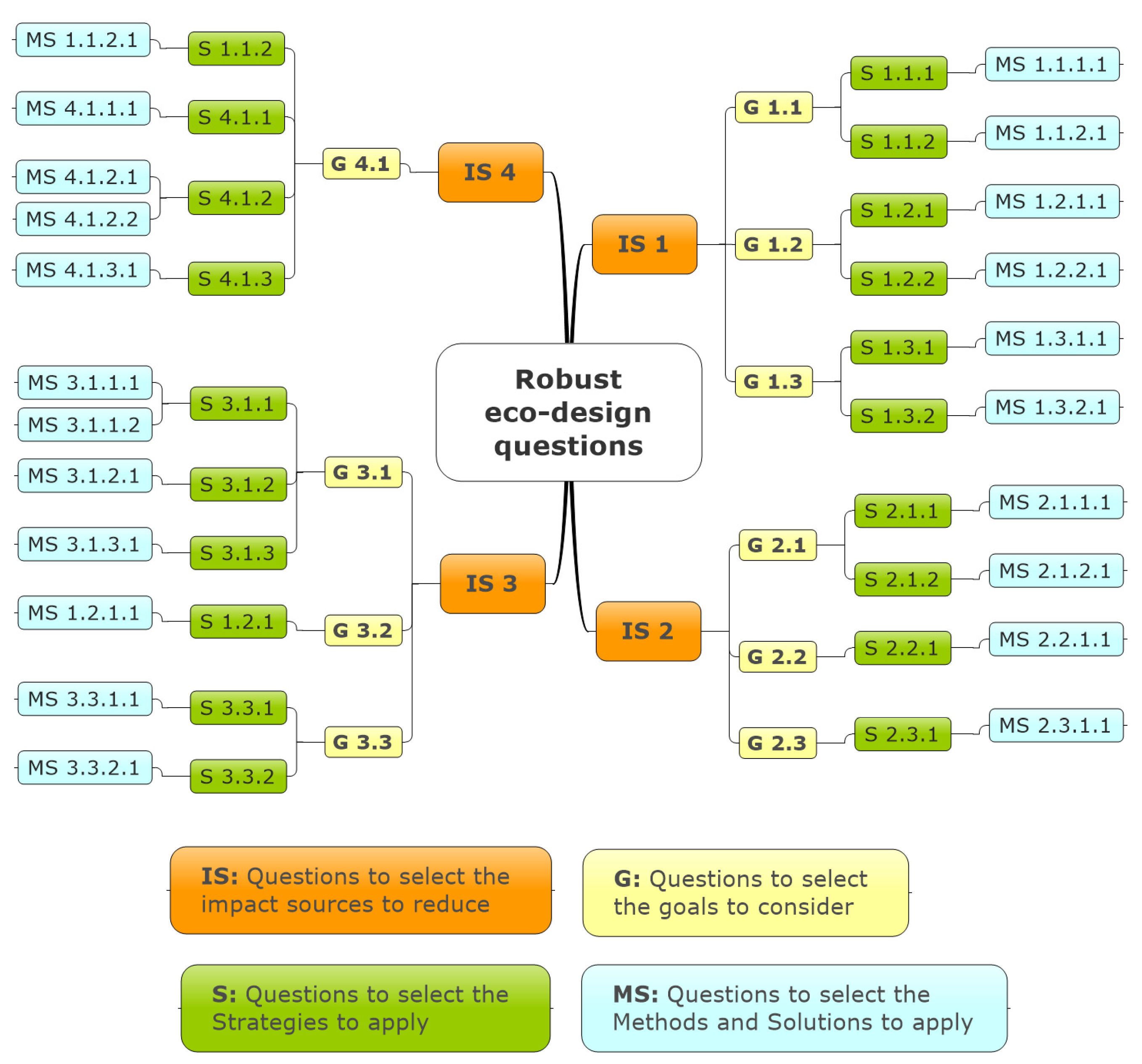
The proposed approach, in line with the philosophy of the inquiry-based method, is based on a series of reformulations of the initial problem (i.e., How to reduce the variability of the environmental impacts of a Technical System?) that led to 52 questions, organised on four levels:
- Impact Sources (IS) (4 questions) pose the problem of selecting which cause of variation in environmental impacts to work on.
- Goals (G) (10 questions) are reformulations of the questions from the previous level that pose some design objectives to work on.
- Strategies (S) (18 questions) concern the possibility of implementing structural interventions to achieve the goals of the previous level.
- Methods and solutions (MS) (20 questions) ask whether certain existing methods of design or robust design can be used to determine a solution to the problem, coherently with the identified strategy and goal.
Figure 2 provides a schematic organisation of the proposed 52 questions properly codified and classified within the proposed four levels of detail.
3.1. Method Application
The starting point for the application of the method is the definition of the initial problem, to be able to accurately select the most appropriate goals and strategies to tackle it, among the many heterogeneous proposals. For this reason, the formulation of the initial problem must be based on the eco-assessment of the Technical System, including all the phases of the life cycle and the knowledge of the anomalies that could cause its variability.
The use of all questions posed by the method is not obligatory to determine solutions or to apply other methods to find them. However, considering different questions in parallel at the same level can expand the number of alternative solutions to the same problem, stimulating the designer to work on several fronts. On the other hand, considering the questions at the sub-levels makes it possible to better circumscribe the perimeter of the problem to be addressed and to refine the solution strategy. The objective to be pursued is the more targeted use of the suggested methods (e.g., FMEA), in order to streamline their application and achieve results more in line with the intended aims.
Moreover, the successful use of the proposed method also depends on the knowledge of the design theories and their correct application. During the definition of goals and strategies, such knowledge is fundamental to better understand the questions, since they include ontological elements and content from these theories, and to interpret them according to what their definitions could evoke. In the application of the suggested methods, the knowledge of the design theories can help to increase the number of results, their qualitative level, and their adherence to the goals, strategies, and the initial environmental problems.
Finally, eco-assessment is also useful for assessing the environmental benefits provided by each identified solution, and for selecting those more suitable to be implemented.
3.2. How the Questions Are Formulated
The proposed questions were carefully formulated both in form and content to fulfil their purpose.
The questions in the first level were modelled with the main aspects of eco-assessment in mind, to provide the method with a coherence on the environmental issue that forms its conceptual basis. The reason stems from the initial aim of reducing the variability of impacts, which makes what is proposed a robust design approach dedicated to approaching environmental problems.
Among the eco-assessment approaches, the LCA methodology, with its key points, was selected for inspiration. This is because it is unanimously considered one of the most useful for quantitatively evaluating the sustainability of current technologies, to critically discuss the choices to be implemented during eco-design and to evaluate the environmental performances of the new developed technologies [30]. In addition, all the considered key points are precisely described in the international reference standards [6] and [31].
Each question in the first level requires working on variations of a key point. They are: the functional unit (i.e., the objective of the operation of the Technical System in terms of processed inputs and obtained outputs over a period of time), the operative scenario (i.e., the conditions of the working environment), and the life cycle inventory (i.e., the structural features of the Technical System and the energy consumptions).
In the questions from the second level onwards, references were made to the ontology and the content of the conceptual design theories, so that the designer could be stimulated in the most appropriate way to find the solutions.
The purpose of the exploited design ontology, drawn from TRIZ and FBS, is to uniquely encode what is stated in the questions, as their definitions are accepted and disseminated. In addition, by using the definitions from the literature, it is also possible for the designer to better interpret and explore the meaning of the same questions.
To facilitate the comprehension of the proposed questions, reported in Section 4, the definitions of the main ontological elements are provided in Table 1.
The content of the second and third level questions are also derived from conceptual design theories. They express some of the most common design problems (contained in the second level questions) and have been formulated and tested with the scientific method by several authors. All these problems were duly addressed by conceptual design theories that provided certain strategies to address them (contained in the third level questions).
In addition, conceptual design theories comprehensively discuss the interactions between the user and the Technical System, discussing the many causes responsible for misuse in a broader and deeper way than robust design approaches do [32]. In conceptual design theories, ample space is devoted to user interface, Function, and manipulation.
The traditional eco-design approaches, based on few (e.g., [33]) or a lot of guidelines (e.g., [34]) or structural optimisation (e.g., [35]), were not considered because their overly rigid objective of reducing environmental impacts (and not their variability) leads them to suggest ready-made solutions rather than making people think about problems and strategies.
The main difficulty in formulating the questions for these two levels was to select the most appropriate strategies for solving the environmental problems of the first level, within the vast literature of conceptual design theories. This was done by analogy in most cases because conceptual design theories rarely make explicit reference to issues of environmental sustainability [36].
Another difficulty was to extrapolate problems and strategies from the conceptual design theories and to divide them appropriately between the second and third levels of our method. This is because, in conceptual design theories, their distinction is often unclear, and their structure is changeable.
The conceptual and robust design methods suggested in the fourth level questions are not the standard ones, but are more specific variants that have been proposed in the literature to specifically address the problems of the higher-level questions. For instance, if we need to specifically improve the user experience by introducing affordances into the structure, we suggest using the framework of [37], which is dedicated to experience affordances and not generic affordances (e.g., [38]).
In some cases, examples of solutions were also proposed in these questions as a substitute for the methods, which were derived from the latter. Their function is not to provide a solution to the designer, but rather a trigger to generate new ideas.
4. Results and Discussions
4.1. Impact Sources Problems
The first level questions aim to stimulate the designer to reduce the variability of the environmental impacts of the Technical System by considering the root cause.
When the Technical System does not work as it should, i.e., does not guarantee the realisation of the functional unit as stated in an LCA, it means that it does not process the expected amount of input or does not generate the expected amount of output, or the outputs obtained do not meet the quality requirements that have been set for the duration of the expected operational life. Consequently, each of these anomalies results in a change in the environmental impacts from the LCA results.
Working on the first Impact Sources selection problem means setting the goal of eliminating the effects of this variability or eliminating it.
The second problem focuses on the effects of changes in the working environment in terms of climate (e.g., pressure, temperature, humidity), geography (e.g., the type of route a car travels), or infrastructure (e.g., electricity mix). Depending on the type of Technical System, these characteristics may in fact influence operation, consumption, and wear.
The third problem asks how variations in environmental impacts resulting from changes in the structural characteristics of the Technical System can be reduced. They may concern materials (e.g., type, mass, and physical characteristics) or geometry and may depend on errors during supply, manufacturing, or wear and damages during use.
Finally, the fourth problem considers the variation in Technical System consumption, which may be due to user misuses or one of the causes of the previous problems.
Table 2 summarizes the questions in the first level.
4.2. Problems in Other Levels
In this section, questions related to the second, third, and fourth level problems are presented and classified according to the Impact Sources selection problem they refer to.
4.2.1. How Can the Effects of the Variability in the Technical System’s Functioning Be Reduced?
This problem was broken down into three Goal identification problems related to:
- The realisation of the Function of the Technical System as planned (G 1.1) to avoid upstream variation in the impacts.
- The prevention of breakage and the limitation of the wear and tear of the Technical System (G 1.2) so that it can properly perform the Function, while maintaining the resulting impacts.
- The avoiding of the early replacement of the Technical System (G 1.3) by the user, so that it can perform the Function for as long as planned, since the early adoption of a new Technical System to perform the same Function results in the generation of new unplanned impacts.
In turn, G 1.1 was linked to two strategy identification problems, which were derived from TRIZ Evolutionary Law No. 5 [26], expressing how Technical Systems evolve by improving the control over their operation. The first (S 1.1.1) poses the problem of monitoring and controlling the Technical System from the outside during operation, e.g., by introducing sensors and asking whether and how the user could intervene if necessary (MS 1.1.1.1). The second (S 1.1.2) is intended to stimulate the designer to identify solutions to make the Technical System autonomous in regulating the mode of execution of the Function, even when the characteristics of the Object should change.
A possibility would be to modify the tool, making it more adaptable and dynamic (MS 1.1.2.1).
The reformulations of G 1.2 concern the possibility of making the Technical System more resistant to failures, so that it can continue to perform its function properly, for example, by using anticipatory failure investigation approaches, or be more easily and ecologically repairable and maintainable.
Finally, to satisfy G 1.2, the proposed strategies aim to avoid the problem of user disaffection towards the Technical System should their needs change over time [39]. For this reason, the Technical System could be modified with more consideration for the future needs of the user and with greater regard to the user experience.
Table 3 reports the questions obtained with the reformulations of the first Impact Sources selection problem.
4.2.2. How Can the Effects of the Variability of the Working Environment Be Reduced?
Three goal identification problems were identified for this problem:
- Avoid using the Technical System when there are variations in environmental conditions (G 2.1), so that possible variation in environmental impacts is avoided regardless.
- Make the implementation of the Function of the Technical System independent of changes in the environmental conditions (G 2.2), so that the impacts resulting from them remain unaltered.
- Do not allow the Structure of the Technical System to deteriorate outside the reference environment (G 2.3) to prevent the production of substances harmful to the environment or toxic to humans.
To realize G 2.1, it is possible to make the Technical System actively involve the user when environmental conditions change (S 2.1.1), using, for example, affordances to prevent it regardless or sensors to detect an anomaly (M 2.1.1.1). Another strategy is to ensure that the Technical System can function only in the proper environment (S 2.1.2), for example, by monitoring external conditions to self-regulate (M 2.1.2.1).
G 2.2 was instead reformulated as a problem of making the energy consumption of the technical system independent of environmental variations (S 2.2.1), e.g., by using renewable energy to break away from the local infrastructure (M 2.2.1.1).
Finally, it has been suggested to address G 2.3 according to the robust design approach (S 2.3.1), designed in a specific variant to avoid environmental problems because of the dispersion of toxic materials (M 2.3.1.1).
Table 4 shows the questions obtained with the reformulations of the second Impact Sources selection problem.
4.2.3. How Can the Effects of the Variability of the Technical System’s Structure Be Reduced?
To solve the third Impact Sources selection problem, three Goal identification problems were identified:
- Increase the reproducibility of the Technical System (G 3.1), to reduce waste during manufacturing and therefore the variability of impacts during the raw material extraction phase.
- Prevent unanticipated deterioration of the Structure of the Technical System (G 3.2) during use and disposal to avoid releasing substances into the environment and failing to perform the Function properly.
- Perform the Function even if the Technical System is structurally deteriorated (G 3.3).
In turn, to obtain G_I 3.1, it is possible to intervene in the production system (S_I 3.1.1), improving its quality from an organisational/management (MS 3.1.1) or plant/structural (MS 3.1.1.2) point of view. On the other hand, it is possible to work specifically on the Structure of the Technical System (S 3.1.2), for example, with the design for manufacturing (MS 3.1.2.1), or to strengthen the Technical System with respect to the problems occurring during manufacturing (S 3.1.3 and M 3.1.3.1).
G 3.2 can be accomplished with previously used strategies, while to achieve G 3.3, it is possible to improve the design of the Structure of the Technical System (S 3.3.1), for example, by using a probabilistic damage tolerant approach (MS 3.3.1.1). Another possibility is to use other resources when its own are no longer available (S 3.3.1) e.g., from the working environment or other systems (MS 3.3.2.1).
Table 5 reports the questions obtained with the reformulations of the third Impact Sources selection problem.
4.2.4. How Can the Effects of the Variability in the Technical System’s Consumption Be Reduced?
From this last problem, only one goal has been identified, i.e., to make sure that the actual and expected behaviour of the Technical System are the same (G 4.1). The reason is that, according to [25], this is a necessary condition for the realisation of the Function according to the prearranged requirements, among which are energetic consumption.
In turn, a possible strategy for achieving G 4.1 is to increase control over how the Function is executed (with the already described S 1.1.2). It is also possible to delegate a role to the Technical System in instructing the user to correct manipulation (S 4.2.1), for example, by introducing affordances (MS 4.2.1.1), or to directly avoid incorrect manipulation (S 4.2.2), redesigning the user interface (MS 4.2.2.1), or inserting automatic controls (MS 4.2.2.2). Finally, the last possibility is to keep the behaviour of the Technical System unchanged even in the presence of user misuse (S 4.2.3), for example, by hardening the Structure design for this eventuality (MS 4.2.3.1).
Table 6 reports the questions obtained with the reformulations of the third Impact Sources selection problem.
5. Results and Discussions
The purpose of this section is to show how the proposed methodology can be applied in a real industrial case study, highlighting the knowledge and other approaches on which it is based and the achieved results, and critically discussing it considering these data.
The selected case study concerns a compressed air dryer, of the adsorption type with hot regeneration, in which the aim is to reduce the variability of environmental impacts. It is used where it is required to remove moisture from a continuous and massive flow of compressed air, typically in oil and gas applications or downstream of a compressor feeding an industrial plant. The main requirements are the quality of the function and the continuity of operation, since the presence of moisture in the compressed air can cause serious problems of wear and reduced efficiency for the powered components.
Its operating principle is based on the chemical process of adsorption, in which the water vapor present in the compressed air is chemically bound to an adsorbent material, i.e., activated alumina. Once saturation is reached, the alumina is regenerated via heating to evaporate the adsorbed moisture. Under conditions of continuous plant operation and a constant processed flow rate, regeneration is performed at regular intervals. Alumina loses some of its adsorptive effectiveness after each regeneration cycle, which is why it is replaced every two years or so.
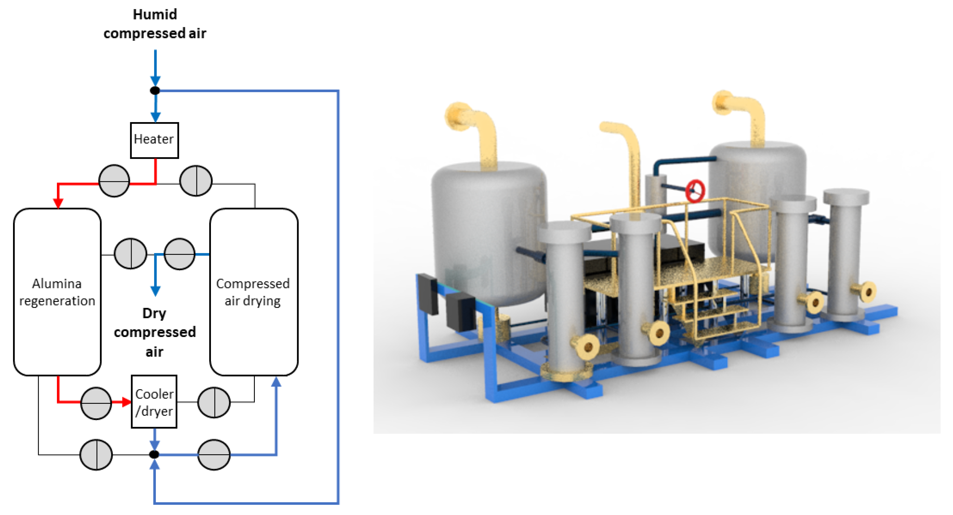
This system is installed immediately downstream of the compressor and consists of two column tanks placed in parallel, inside of which the alumina is contained. They work in an alternating way: during phase 1, the compressed air is dried in one tank, and in the other, the alumina is hot regenerated, and vice versa during phase 2. For the regeneration, the alumina is heated with a stream of hot air that is drawn from the same flow rate of compressed air just produced by the compressor and heated by a heater. The hot, moist air exiting this tank is then dehumidified by means of a chiller with a condensate separator and combined with the main flow of compressed air before entering the drying column.
Figure 3 depicts a schematic representation of the components of the Technical System and an illustrative CAD model.
5.1. Preliminary Analysis
The proposed method has been tested on the considered Technical System by the same authors during a consulting activity for an Italian manufacturing company. The test was preceded by an LCA study that determined the baseline impacts of the Technical System and the analysis of the operational parameter variability throughout the life cycle.
The LCA study conducted was limited to the calculation of the global warming potential (kg CO2 eq.), by strictly applying the [6] and [31] standards.
The functional unit is the dehumidification of 1500 Nm3/h of compressed air flow, having a nominal operating pressure of the system equal to 8.5 bar and an inlet temperature of 50 °C, during a life time of 20 years (24 h a day, 365 days), considering the Russian context (Omsk region).
The scope of the study is to perform a comparative analysis of the environmental performance of a compressed air dryer in standard conditions and after variations in some functioning parameters hypothesised by following the proposed method.
The life cycle inventory was carried out by considering all the phases of the product’ life cycle. Data about pre-manufacturing (raw material extraction) were collected from the product bill of material provided by the company. The same company also provided data about manufacturing processes, supplying logistics, and internal logistics. In these cases, the “Allocation default content System Model” was considered to partition and allocate burdens and credits when dealing with the conversion from multi-product datasets to a single-product dataset. Data about distribution logistics were retrieved by considering standard routes (with combined road and rail transport) already followed by the company. Data related to the energy consumption of the product have been measured by the company through experimental tests performed within the company, and they have been properly corrected by using theoretical coefficients of conversion (i.e., environmental temperature and pressure ratios) to relate them to the operative contexts. Data about maintenance frequency and energy were collected by the company from its main customers located in the operative scenario. Data about end-of-life are derived from the hypothesis of disposing the product at the installation site, without considering material recycling as indicated by the customers and logistics. Environmental impact calculations were performed by using the EcoInvent v. 3 database and the electricity mix of the product’s place of installation.
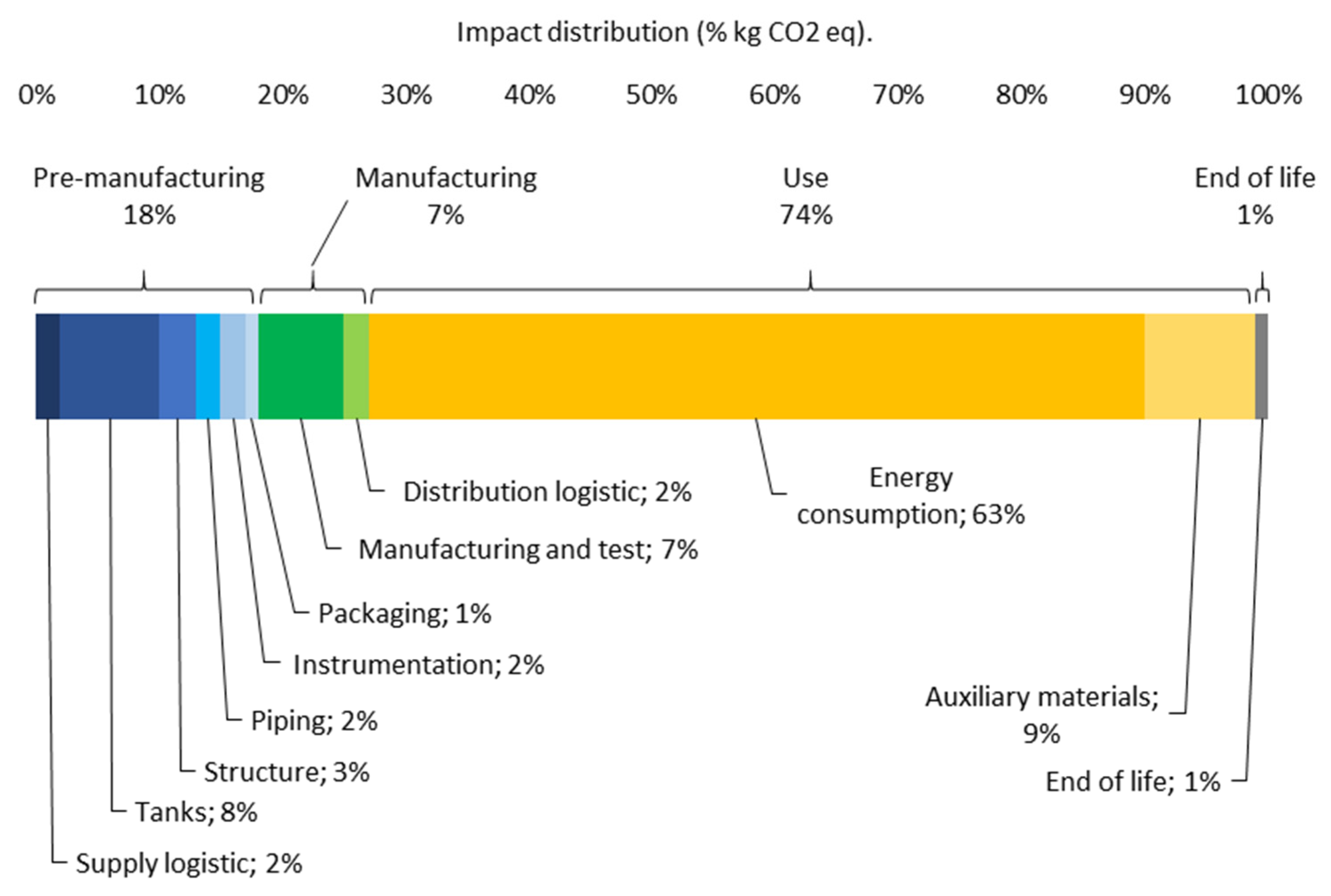
The obtained results (see Figure 4) showed a distribution of impacts strongly unbalanced towards the use phase due to the high energy consumption by the heater during its operational life and by the auxiliary materials, mainly consisting of alumina. Among the impacts of the pre-manufacturing phase, those of the tanks are especially high, due to their size and the amount of steel they are made of. Manufacturing impacts, on the other hand, come primarily from cutting and welding.
After the quantification of the environmental impacts, the starting problem has been defined, i.e., to identify in which way and in which phases of the life cycle of the Technical System that its environmental impacts could change. This led to the defining of three problems:
- Rarely, some facilities experienced an unanticipated increase in use-phase impacts due to increased compressor consumption, which was required to process a higher compressed air flow rate than required.
- It is possible that during the use phase there will be an increase in impacts attributable to the consumption of auxiliary materials. The main cause is the excessive consumption of alumina, which must be replaced soon when the Technical System is used to dehumidify an excessive flow of compressed air.
- The environmental impacts resulting from the facility could be greater than originally esteemed due to the anticipated replacement of the compressed air lines feeding the two tanks. This is because they wear from corrosion more than they should, thinning to the point of puncturing in several places and causing rapid depressurisation of the system and its blockage.
In the following paragraphs, the results of the application of the methodology are reported, classifying them according to the addressed problem, specifying the used questions, and reporting the benefits for the reduction of environmental impacts compared to the basic configuration of the LCA, either qualitatively or quantitatively.
5.1.1. Method Application
Initial Problem N.1
The flow rate of air that is dehumidified is one of the main parameters of the functional unit, and its variation goes to completely influence its working mode, even before the behaviour and other aspects that will adapt accordingly. For this reason, to face this initial problem, IS 1 (How can the effects of the variability of the technical system functioning be reduced?) is among the questions of the first level.
By reframing the problem in these terms, we are led to reason explicitly about possible inefficiencies during the dryer’s operation. According to TRIZ jargon, reducing the variability in the function means making sure that the characteristics of the Product (i.e., the dried compressed air) are exactly as expected. While, if the compressor processes more compressed air, it means that the dryer cannot produce as much as is required downstream. Consequently, the problem to be solved is preventing flow losses inside the dryer.
Due to the generality with which this problem is posed, the solutions can theoretically concern the waterproofing of the whole dryer. Consequently, the goal G 1.2 (How can the Technical System not break down or degrade prematurely during use?) was selected. By researching only those components of the air dryer that might break or degrade during its operation, thus causing the variability, the problem to be solved narrows. In addition, again at this stage we can make an additional effort in reframing the problem, asking which parts or components of the Technical System should not break so as not to affect the realisation of its Function. Consequently, the problem becomes reducing the pressure drop inside the tank where the drying takes place.
Possible solutions are various, including modification of its internal volume (e.g., with a mobile membrane), the better arrangement of alumina to avoid pressure drops, and interventions on the three ducts connected to it.
By applying strategy S 1.2.1 (How can the Technical System be made more resistant to failures?) it is possible to focus exclusively on those components that can fail. The problem to be solved then becomes making the three ducts connected to the drying tank more resistant to failure. While using FMEA, as one of the options suggested by MS 1.2.1.1 to solve this problem, a more streamlined analysis can be conducted than by applying it during the previous steps, since we considered only the ducts communicating with the drying tank instead of the entire Technical System.
The use of FMEA applied in this way allowed the identification of the failure to close one of the duct valves as a Failure Mode, which is associated with the leakage of air and therefore the pressure drop inside the drying tank (Failure Effect). The Failure Cause that has been associated with this anomaly is the loss of pressure in the pneumatic actuating system of the valve, caused by an occlusion of its circuit due to the accumulation of dust inside, which can enter when one of the seals between the valve and the duct is worn.
The proposed solution was to replace the rubber gaskets with copper models. It allows for avoiding an increase of 0.6 kg CO2 eq. for each minute in which the compressor processes the compressed air overflow, considering an increase in the required compressor power equal to 10% of the nominal value in the baseline configuration, which is compatible with the depressurisation induced by the rupture of the seals adopted in this operating scenario, and depending on the type of used compressor. This result was obtained by considering the initial impact of copper.
Initial Problem N.2
As it is formulated, this problem is mainly related to variations in the use phase of the Technical System (IS 4), and therefore the goal to be achieved is G 4.1 (How can the actual behaviour of the Technical System be the same as its expected behaviour (described in the LCA)?).
To not degrade the alumina prematurely, it is necessary for the flow rate of the compressed air it dehumidifies to remain as set. Possible solutions therefore concern both the management of the compressed air flow, upstream of the system and within it.
Following S 4.1.3 (How can the behaviour of the Technical System remain the same after user misuse?), we only work on internal Technical System improvements, i.e., downstream of possible user misuses, mitigating their effects. This means, therefore, that the user can command the compressor to process a higher flow of compressed air, but the alumina inside the drying tank only needs to be hit by the correct flow.
The solution identified by applying MS 4.1.3.1 has the objective of intercepting the overflow of compressed air before it reaches the alumina, ensuring that the Technical System itself can achieve it, in line with the principles of robust design. It consists of introducing a small tank containing a stock of alumina, flanking the main tanks, and communicating with them via a duct with a spring-loaded hatch calibrated to standard compressed air pressure. Normally, the hatch is closed, but if there is an overflow of compressed air, it opens, increasing the total volume of the adsorption tank and allowing the additional alumina to perform part of the dehumidification. Once the overflow of compressed air has been disposed of, the hatch closes again. This solution, with a sparing use of the Technical System in off-design mode, allows the consumption of back-up alumina to be kept almost unchanged. The saved environmental impacts are 4.26 kg CO2 eq. for each m3/h of overflowed compressed air processed in the Technical System, compared to the baseline configuration.
Other simpler solutions to the problem, which derive from the application of S 4.1.2, involve the introduction of a digital flow rate gauge on board the machine, with a bi-color green/red warning light and acoustic signal, to indicate when the compressed air flow rate exceeds the limit value.
Initial Problem N.3
To address this problem, which is clearly associated with IS 3, the goal is to prevent or reduce unintended deterioration of the Structure of the Technical System during use (G 3.2).
Therefore, re-applying S 1.2.1 and M 1.2.1.1 to solve this problem, several solutions were assumed, and among them, only those involving minimal interventions to the system were selected, so as not to vary the impacts of the baseline option of the LCA.
Nickel plating, which would only be applied to the inner surface of the compressed air pipes, was chosen as one of the possible solutions. In this case, avoiding the extraordinary replacement of the pipes of the compressed air circuit would save an impact of 983 kg CO2 eq. compared to the baseline configuration, equal to 2% of the total impact of the Structure, which is greater than the the galvanisation intervention, which involves an increase of only 49 kg CO2 eq. This result was obtained by considering the initial impact of Nickel plating.
5.2. Other Case Studies
The method was also applied to another real industrial case study, i.e., a three-phase medium-voltage switch produced by a multinational company active in the sector.
This device works to interrupt three-phase medium voltage power lines. Its core components are three busbars made of copper, one for each phase, connected to electrical cables. Each busbar consists of two cylindrical parts, placed vertically on top of each other, one fixed and one movable, and contained within an SF6 ampoule. When the switch is closed, the two parts of each busbar are in contact, and the current flows from one to the other, whereas when the switch is open, the moving part is raised a certain distance so that no current can flow. The SF6 gas, inside the ampoule, is used to rapidly extinguish the current arc when the two parts of the busbar are detached. Their opening is lightning fast and is obtained by means of a sudden snap action provided by pre-loaded springs.
As in the case of the previous case study, the environmental impacts of this device in the baseline condition were assessed by rigorously applying the LCA methodology. The considered functional unit is the functioning of the device in the standard condition over 20 years, in the context of northern Italy. The goal of the study is the same as the previous case study. The life cycle inventory was performed by acquiring all the data about pre-manufacturing, manufacturing, logistics from the bill of material, and other information provided by the company. The data about the use phase were retrieved by simulating the plate operation established by the standard shared product category and by considering the results about a single operation, obtained through internal experimental tests. Data about distribution logistics and end-of-life were obtained by considering the same criteria as the previous case study.
The distribution of the environmental impacts resulting from the LCA carried out on this Technical System showed the predominant role of those derived from electrical dissipation during the use phase when the switch is closed, due to the resistance imposed by the Structure, replacing about 60% of the total. Other impacts are mainly due to the raw materials extraction.
Moreover, in this case, the answers to the proposed questions allowed for determining and describing possible faults of the Technical System and solving them by introducing proper solutions.
By answering the questions IS 1, G 1.1, S 1.1.1, and MS 1.1.1.1, we proposed to monitor the fluid-dynamic conditions of the SF6 gas, to prevent its inability to interrupt the arc when there is a drop in pressure due to a leak from a damaged seal, through the introduction of pressure sensors within the ampoules. The damage to the seals is mainly due to their aging. The correct functioning of the circuit-breaker guarantees the protection of the devices protected by it (e.g., turbogas for the production of energy) and the lack of environmental impacts deriving from their damage.
By answering the questions IS 4, G 4.1, S 4.1.3, and MS 4.1.3.1, we identified, among the possible problems occurring to the device during maintenance, the misalignment between the fixed and the movable parts of the busbars, caused by the human intervention of the operator. The consequence of this fact was associated with the increase in the electrical resistance of the device when the busbars are closed and the current flows through. The introduction of a magnetic collar, identified among the patents related to medium-voltage switches, could prevent the misalignments of the busbars and the annual current losses estimated at 1%, compared to the baseline configuration.
6. Conclusions
The approach on which the method proposed in this article is based (i.e., inquiry-based) made it possible to group and classify methods, approaches. and solutions that can be useful in reducing variations in environmental impacts. The salient point is to provide the designer with a goal and a strategy to work on and to organise the resolution of this problem in the structured manner of the conceptual design theories. This fact is unusual, since it expands their traditional application domain, which is limited to the development of a new device. Although the proposed method has the objective of solving environmental problems, its validity is more general, as it can be used as a robust design method also dedicated to more generic types of problems.
In more detail, the proposed method provides clarity on the many possible interventions, combining support for the elimination of device failures, unwanted effects of the external environment, and users’ misuses. On the other hand, the application of the suggested methods and solutions can be more targeted and streamlined if the formulated problems are explicitly addressed according to the suggested goals and strategies. This means saving time and costs, especially for more structured methods such as FMEA. The questions were formulated to be easily understood, especially by those not familiar with design theories, simplifying the statement of content as much as possible and using a specific ontology that has been reduced to a minimum.
The results obtained with the application of the proposed method on the case studies are very different from each other both in terms of operation and from a structural point of view, as well as the goals and strategies used to achieve them. The enlargement of the solution space is an advantage in a design method. While the quantification of the reduction in environmental impacts makes us realise that similar and equally large benefits can be obtained from quite different solutions, derived from different goals and strategies, thus confirming the initial assumption.
Nevertheless, some recommendations are still necessary for those who wish to apply the method. The proposed method is to be considered as initial work as it concerns the provided questions and the list of recommended methods that can be improved. This is because the real objective of the paper is to illustrate the advantages of the conceptual design theories to organise the solution to the addressed problem and demonstrate that the inquiry-based method could be the key to achieving such contamination. The determination of anomalies in the Technical System, as performed in the case study, depends on the data collected during its use. This does not preclude the application of the proposed method during the design of the Technical System, provided that the anomalies are assumed beforehand. The risk here is to quantify too roughly the variations in environmental impacts due to anomalies, and consequently the evaluation of the obtained solutions. Finally, a good knowledge of design theories is an important prerequisite for the best application of the method. More experienced users are more likely to choose more suitable goals and strategies to be modelled and solved, knowing better the ontological definitions of design theories at the base of the questions. They may also have a greater advantage in identifying solutions that make more rational use of resources, and for this reason, they can also be more sustainable, so as not to nullify the benefits they can achieve in reducing the impact variations.
Future developments of this method should therefore consider very carefully the weaknesses arising from these recommendations. Improving the ontological structure, expanding the number of questions, and suggesting new methods and approaches to implement goals and strategies could be the most obvious targets that other researchers could focus on.
Funding
This research received no external funding.
Institutional Review Board Statement
Not applicable.
Informed Consent Statement
Not applicable.
Data Availability Statement
The data presented in this study are available on request from the corresponding author. The data are not publicly available due to personal details of test participants.
Conflicts of Interest
The authors declare no conflict of interest.
References
- Ahmad, S.; Wong, K.Y.; Tseng, M.L.; Wong, W.P. Sustainable product design and development: A review of tools, applications and research prospects. Resour. Conserv. Recycl. 2018, 132, 49–61. [Google Scholar] [CrossRef]
- Rossi, M.; Germani, M.; Zamagni, A. Review of ecodesign methods and tools. Barriers and strategies for an effective implementation in industrial companies. J. Clean. Prod. 2016, 129, 361–373. [Google Scholar] [CrossRef]
- Ma, X.; Moultrie, J. What stops designers from designing sustainable packaging?—A review of eco-design tools with regard to packaging design. In Proceedings of the International Conference on Sustainable Design and Manufacturing, Cambridge, UK, 26 April 2017; Springer: Berlin/Heidelberg, Germany, 2017; pp. 127–139. [Google Scholar]
- Ray, B.C.; Rathore, D. Environmental damage and degradation of FRP composites: A review report. Polym. Compos. 2015, 36, 410–423. [Google Scholar] [CrossRef]
- Bugge, H.C.; Dalhammar, C.; Maitre-Ekern, E. Developing Legislation to Prevent Environmental Damage from Products: A Herculean but Necessary Task; Lund University Publications: Lund, Sweden, 2018. [Google Scholar]
- International Organization for Standardization. 14040:2006 Environmental Management—LCA—Principles and Framework; International Organization for Standardization: Geneva, Switzerland, 2006. [Google Scholar]
- Bransford, J.D.; Brown, A.L.; Cocking, R.R. How People Learn; National Academy Press: Washington, DC, USA, 2000; Volume 11. [Google Scholar]
- Dorst, K.; Cross, N. Creativity in the design process: Co-evolution of problem–solution. Des. Stud. 2001, 22, 425–437. [Google Scholar] [CrossRef] [Green Version]
- Borgianni, Y.; Maccioni, L.; Pigosso, D. Environmental lifecycle hotspots and the implementation of eco-design principles: Does consistency pay off? In Proceedings of the International Conference on Sustainable Design and Manufacturing, Budapest, Hungary,, 4–5 June 2019; Springer: Singapore; pp. 165–176. [Google Scholar]
- Kania, A.; Roszak, M.; Spilka, M. Evaluation of FMEA methods used in the environmental management. Arch. Mater. Sci. Eng. 2014, 65, 37–44. [Google Scholar]
- Cherrafi, A.; Elfezazi, S.; Chiarini, A.; Mokhlis, A.; Benhida, K. The integration of lean manufacturing, Six Sigma and sustainability: A literature review and future research directions for developing a specific model. J. Clean. Prod. 2016, 139, 828–846. [Google Scholar] [CrossRef]
- Panchal, D.; Mangla, S.K.; Tyagi, M.; Ram, M. Risk analysis for clean and sustainable production in a urea fertilizer industry. Int. J. Qual. Reliab. Manag. 2018, 35, 1459–1476. [Google Scholar] [CrossRef]
- Siler-Evans, K.; Azevedo, I.L.; Morgan, M.G.; Apt, J. Regional variations in the health, environmental, and climate benefits of wind and solar generation. Proc. Natl. Acad. Sci. USA 2013, 110, 11768–11773. [Google Scholar] [CrossRef] [PubMed] [Green Version]
- Olsson, P.; Galaz, V.; Boonstra, W.J. Sustainability transformations: A resilience perspective. Ecol. Soc. 2014, 19, 1–14. [Google Scholar] [CrossRef] [Green Version]
- Ten Napel, J.; Van Der Veen, A.A.; Oosting, S.J.; Koerkamp, P.G. A conceptual approach to design livestock production systems for robustness to enhance sustainability. Livest. Sci. 2011, 139, 150–160. [Google Scholar] [CrossRef]
- Ijomah, W.L.; McMahon, C.A.; Hammond, G.P.; Newman, S.T. Development of robust design-for-remanufacturing guidelines to further the aims of sustainable development. Int. J. Prod. Res. 2007, 45, 4513–4536. [Google Scholar] [CrossRef]
- Gremyr, I.; Siva, V.; Raharjo, H.; Goh, T.N. Adapting the Robust Design Methodology to support sustainable product development. J. Clean. Prod. 2014, 79, 231–238. [Google Scholar] [CrossRef] [Green Version]
- Kuo, T.C.; Wang, C.J. Integrating robust design criteria and axiomatic design principles to support sustainable product development. Int. J. Precis. Eng. Manuf. Green Technol. 2019, 6, 549–557. [Google Scholar] [CrossRef]
- McGrenere, J.; Ho, W. Affordances: Clarifying and evolving a concept. In Proceedings of the Graphics Interface: 2000, Montréal, QC, Canada, 15–17 May 2000; Volume 2000, pp. 179–186. [Google Scholar]
- Bruno, F.; Muzzupappa, M. Product interface design: A participatory approach based on virtual reality. Int. J. Hum. Comput. Stud. 2010, 68, 254–269. [Google Scholar] [CrossRef]
- Kaptelinin, V. Affordances and Design; The Interaction Design Foundation: Aarhus, Denmark, 2014. [Google Scholar]
- Bhamra, T.; Lilley, D.; Tang, T. Design for sustainable behaviour: Using products to change consumer behaviour. Des. J. 2011, 14, 427–445. [Google Scholar] [CrossRef]
- Lilley, D. Design for sustainable behaviour: Strategies and perceptions. Des. Stud. 2009, 30, 704–720. [Google Scholar] [CrossRef] [Green Version]
- Pahl, G.; Beitz, W. Engineering Design: A Systematic Approach; Springer: Berlin/Heidelberg, Germany, 2013. [Google Scholar]
- Gero, J.S. Design prototypes: A knowledge representation schema for design. AI Mag. 1990, 11, 26. [Google Scholar]
- Altshuller, G.S. Creativity as an Exact Science: The Theory of the Solution of Inventive Problems; Gordon and Breach Science Publishers: Philadelphia, PA, USA, 1984. [Google Scholar]
- Mooney, M.A.; Laubach, T.A. Adventure engineering: A design centered, inquiry based approach to middle grade science and mathematics education. J. Eng. Educ. 2002, 91, 309–318. [Google Scholar] [CrossRef]
- Abdi, A. The effect of inquiry-based learning method on students’ academic achievement in science course. Univers. J. Educ. Res. 2014, 2, 37–41. [Google Scholar] [CrossRef]
- Bayram, Z.; Oskay, Ö.Ö.; Erdem, E.; Özgür, S.D.; Şen, Ş. Effect of inquiry based learning method on students’ motivation. Procedia-Soc. Behav. Sci. 2013, 106, 988–996. [Google Scholar] [CrossRef] [Green Version]
- Hauschild, M.Z.; Rosenbaum, R.K.; Olsen, S.I. Life Cycle Assessment; Springer: Berlin/Heidelberg, Germany, 2018. [Google Scholar]
- International Organization for Standardization. 14044:2006—Environmental Management—LCA—Requirements and Guidelines; International Organization for Standardization: Geneva, Switzerland, 2006. [Google Scholar]
- Fahl, J.; Hirschter, T.; Haag, S.; Staiger, T.; Albers, A. Functions in the early phase of product development: A systematic literature review. In Proceedings of the 2020 IEEE International Symposium on Systems Engineering (ISSE), Vienna, Austria, 12 October–12 November 2020; pp. 1–9. [Google Scholar]
- Luttropp, C.; Lagerstedt, J. EcoDesign and The Ten Golden Rules: Generic advice for merging environmental aspects into product development. J. Clean. Prod. 2006, 14, 1396–1408. [Google Scholar] [CrossRef]
- Russo, D.; Spreafico, C. TRIZ-based guidelines for eco-improvement. Sustainability 2020, 12, 3412. [Google Scholar] [CrossRef] [Green Version]
- Russo, D.; Rizzi, C. Structural optimization strategies to design green products. Comput. Ind. 2014, 65, 470–479. [Google Scholar] [CrossRef]
- Anand, A.; Khan, R.A.; Wani, M.F. Development of a sustainability risk assessment index of a mechanical system at conceptual design stage. J. Clean. Prod. 2016, 139, 258–266. [Google Scholar] [CrossRef]
- Pucillo, F.; Cascini, G. A framework for user experience, needs and affordances. Des. Stud. 2014, 35, 160–179. [Google Scholar] [CrossRef]
- Kannengiesser, U.; Gero, J.S. A process framework of affordances in design. Des. Issues 2012, 28, 50–62. [Google Scholar] [CrossRef]
- Cascini, G.; Montagna, F. Modelling (pre-) design activities with a multi-stakeholder perspective. In Principia Designae-Pre-Design, Design, and Post-Design; Springer: Tokyo, Japan, 2015; pp. 175–197. [Google Scholar]
- Desai, A.; Mital, A. Design for maintenance: Basic concepts and review of literature. Int. J. Prod. Dev. 2006, 3, 77–121. [Google Scholar] [CrossRef]
- Afshari, H.; Peng, Q.; Gu, P. Reducing effects of design uncertainties on product sustainability. Cogent Eng. 2016, 3, 1231388. [Google Scholar] [CrossRef]
- Kovach, J.; Stringfellow, P.; Turner, J.; Cho, B.R. The house of competitiveness: The marriage of agile manufacturing, design for Six Sigma, and lean manufacturing with quality considerations. J. Ind. Technol. 2005, 21, 1–10. [Google Scholar]
- Prashanth, K.G.; Scudino, S.; Chatterjee, R.P.; Salman, O.O.; Eckert, J. Additive manufacturing: Reproducibility of metallic parts. Technologies 2017, 5, 8. [Google Scholar] [CrossRef] [Green Version]
- Zu, X.; Fredendall, L.D.; Douglas, T.J. The evolving theory of quality management: The role of Six Sigma. J. Oper. Manag. 2008, 26, 630–650. [Google Scholar] [CrossRef]
- Schevenels, M.; Lazarov, B.S.; Sigmund, O. Robust topology optimization accounting for spatially varying manufacturing errors. Comput. Methods Appl. Mech. Eng. 2011, 200, 3613–3627. [Google Scholar] [CrossRef] [Green Version]
- Miedlar, P.C.; Berens, A.P.; Gunderson, A.; Gallagher, J.P. Analysis and Support Initiative for Structural Technology (ASIST) Delivery Order 0016: USAF Damage Tolerant Design Handbook: Guidelines for the Analysis and Design of Damage Tolerant Aircraft Structures; University of Dayton Research Institute: Dayton, OH, USA, 2002. [Google Scholar]
- Spreafico, C.; Fantoni, G.; Russo, D. FBS models: An attempt at reconciliation towards a common representation. In Proceedings of the International Conference on Engineering Design, Iced15, Milano, Italy, 27–30 July 2015. [Google Scholar]
- Palme, M.; Isalgue, A.; Coch, H.; Serra, R. Robust design: A way to control energy use from human behavior in architectural spaces. In Proceedings of the PLEA Conference, Geneva, Switzerland, 6–8 September 2006. [Google Scholar]
- Spreafico, C. Quantifying the advantages of TRIZ in sustainability through life cycle assessment. J. Clean. Prod. 2021, 303, 126955. [Google Scholar] [CrossRef]
- Bersano, G.; Fayemi, P.E.; Schoefer, M.; Spreafico, C. An eco-design methodology based on a-LCA and TRIZ. In Proceedings of the International Conference on Sustainable Design and Manufacturing, Bologna, Italy, 26–28 April 2017; Springer: Berlin/Heidelberg, Germany; pp. 919–928. [Google Scholar]
- Mekki, K.S. Robust design failure mode and effects analysis in designing for Six Sigma. Int. J. Prod. Dev. 2006, 3, 292–304. [Google Scholar] [CrossRef]
Figure 1.
The proposed method works in the intersection between design theories, knowledge about the Technical System and eco-assessment.
Figure 1.
The proposed method works in the intersection between design theories, knowledge about the Technical System and eco-assessment.

Figure 2.
Schematic organisation of the proposed 52 questions within the 4 proposed levels of detail.
Figure 2.
Schematic organisation of the proposed 52 questions within the 4 proposed levels of detail.

Figure 3.
Schematic representation of the components and connections of the Technical System (left) and its CAD model (right).
Figure 3.
Schematic representation of the components and connections of the Technical System (left) and its CAD model (right).

Figure 4.
CO2 distribution of the environmental impacts of the life cycle of the Technical System among the constituting phases and ITEMS.
Figure 4.
CO2 distribution of the environmental impacts of the life cycle of the Technical System among the constituting phases and ITEMS.


Table 1.
Definitions of the main ontological elements.
| Ontological Elements | Definitions |
|---|---|
| Function | The action performed by the Technical System [26] |
| Object | The entity over which the Technical System performs the Function [26] |
| Product | The transformed Object after the Function has been performed [26] |
| Behavour | How the structure of an artefact achieves its functions. It is divided into expected behavour, by the user or the designer, and actual behavour, which is realised by the Technical System [25] |
| Structure | The components and the materials which make up an artefact (i.e., the Technical System) and their relationships [25] |
| Tool | The part of the Technical System that is in direct contact with the Object during the performance of the Function. The contact can be mechanical, acoustical, thermal, chemical, electrical, magnetic, intermolecular, or biological [26] |
| Other elements of the Technical System |
|
| Resource | Any substance, including waste, available in the Technical System or in the working environment. An energy reserve, free time, unoccupied space, information. Physical, chemical, geometric properties of the substances [26] |
Table 2.
Types of Impact sources (IS) selection problems.
| IS 1 | How can the effects of the variability in the Technical System’s functioning be reduced? |
| IS 2 | How can the effects of the variability in the working environment be reduced? |
| IS 3 | How can the effects of the variability in the Technical System’s structure be reduced? |
| IS 4 | How can the effects of the variability in the Technical System’s consumption can be reduced? |
Table 3.
Design problems related to the reduction of the variability in the Technical System’s functioning (where G = goals, S = strategies, MS = methods and solutions).
Table 3.
Design problems related to the reduction of the variability in the Technical System’s functioning (where G = goals, S = strategies, MS = methods and solutions).
| Goals Problems | Strategies Problems | Methods and Solutions Problems |
|---|---|---|
| G 1.1: How can the Technical System always perform its Function in the same way throughout the use phase? | S 1.1.1: How can the Technical System be monitored and controlled during its functioning? | MS 1.1.1.1: Can sensors be introduced into the technical system to monitor its status and the environmental conditions to alert the user or communicate with an automatic controller? |
| S 1.1.2: How can the Technical System Tool be modified so that it interacts with the Object in a more controlled way? | MS 1.1.2.1: Can the Tool be redesigned or modified to facilitate maintenance, decrease wear, or adapt it better to the physical and morphological characteristics of the Object? | |
| G 1.2: How can the Technical System not break down or degrade prematurely during use? | S 1.2.1: How can the Technical System be made more resistant to failures? | MS 1.2.1.1: Are failure determination approaches (e.g., Anticipatory Failure Investigation, Failure Mode, and Effect Analysis and Fault Tree Analysis) able to identify new potential failures to be avoided? |
| S 1.2.2: How can the Technical System be made self-repairing or more easily and ecologically repairable and maintainable? | MS 1.2.2.1: Can the suggestions contained in Design for Sustainable Maintenance (e.g., [40]) be applied to the Technical System? | |
| G 1.3: How can the Technical System meets the user’s needs, even when they change, so that they do not throw it away prematurely? | S 1.3.1: How can the Technical System be redesigned by better consider the current and future user needs? | MS 1.3.1.1: Can Quality Function Deployment for environmental problems [41] help define how to modify the Technical System? |
| S 1.3.2: How can the Technical System be redesigned to create user loyalty? | MS 1.3.2.1: Could the introduction of experience affordances [37] be a solution? |
Table 4.
Design problems related to the reduction in the variability of the Technical System’s environmental impacts arising from the modification of the working environment (where G = goals, S = strategies, MS = methods and solutions).
Table 4.
Design problems related to the reduction in the variability of the Technical System’s environmental impacts arising from the modification of the working environment (where G = goals, S = strategies, MS = methods and solutions).
| Goals Problems | Strategies Problems | Methods and Solutions Problems |
|---|---|---|
| G 2.1: How can it be ensured that the Technical System is not used outside of its reference environment? | S 2.1.1: How would the Technical System instruct the user not to use it outside of the reference environment? | MS 2.1.1.1: Would modifying the Structure of the Technical System by introducing sensors or affordances be a solution? |
| S 2.1.2: How could the Technical System fail to work outside of the reference environment? | MS 2.1.2.1: How could environmental conditions be monitored and active or passive lockdown systems be introduced into the Technical System? | |
| G 2.2: How could the technical system continue to perform the Function in the same way outside the working environment? | S 2.2.1: How could the Technical System’s energy consumption be decoupled from the working environment? | MS 2.2.1.1: Is it possible to make the Technical System energy self-sufficient with respect to the local infrastructure, e.g., by using renewable energy or importing energy from elsewhere? |
| G 2.3: How could the Structure of the Technical System not deteriorate outside the working environment? | S 2.3.1: How can the Structure design of the Technical System be strengthened with respect to environmental factors? | MS 2.3.1.1: Is it possible to find solutions by applying the robust design approach for environmental problems [17]? |
Table 5.
Design problems related to the reduction of the variability in the Technical System’s structural features (where G = goals, S = strategies, MS = methods and solutions).
Table 5.
Design problems related to the reduction of the variability in the Technical System’s structural features (where G = goals, S = strategies, MS = methods and solutions).
| Goals Problems | Strategies Problems | Methods and Solutions Problems |
|---|---|---|
| G 3.1: How can the variability in the Structure of the Technical System be prevented or reduced by improving its reproducibility? | S 3.1.1: How can the quality of the Technical System’s production process be improved? | MS 3.1.1.1: Is it possible to implement incremental improvements to current manufacturing technologies to improve their manufacturing quality, e.g., Six Sigma [42]? |
| MS 3.1.1.2: Is it possible to employ new manufacturing technologies that increase the reproducibility of the Technical System’s Structure (e.g., [43])? | ||
| S 3.1.2: How can the Technical System be improved by making it more reproducible? | MS 3.1.2.1: Is it possible to redesign the Technical System’s Structure to make it more reproducible, e.g., Design for Manufacturing [44]? | |
| S 3.1.3: How can anomalies during manufacturing be prevented from affecting the Technical System? | MS 3.1.3.1: How can the design of the Technical System’s Structure be improved with Robust design for manufacturing problems (e.g., [45])? | |
| G 3.2: How can unanticipated deterioration of the Structure of the Technical System be prevented or reduced during use? | See S 1.2.1 | See MS 1.2.1.1 |
| G 3.3: How can you make the Technical System perform the Function as expected even if its Structure deteriorates? | S 3.3.1: How can the Structure of the Technical System be improved to make it work even when deteriorated? | MS 3.3.1.1: How can the Structure of the Technical System be improved by applying a probabilistic approach, e.g., Design for Damage Tolerant [46]? |
| S 3.3.2: How can you make sure that the Technical System is able to take advantage of the Resources available to perform the Function even when it is no longer able because its Structure is too deteriorated to do so? | MS 3.3.2.1: Could the Technical System be included in a supersystem, using its resources to perform the Function, when it is no longer capable, as in Evolutionary Law No. 6 [26]? |
Table 6.
Design problems related to the reduction of the variability in the Technical System’s consumption (where G = goals, S = strategies, MS = methods and solutions).
Table 6.
Design problems related to the reduction of the variability in the Technical System’s consumption (where G = goals, S = strategies, MS = methods and solutions).
| Goals Problems | Strategies Problems | Methods and Solutions Problems |
|---|---|---|
| G 4.1: How can the actual behaviour of the Technical System be the same as its expected behaviour (described in the LCA)? | See S 1.1.2 | See MS 1.1.2.1 |
| S 4.1.1: How can the Technical System be made to instruct the user to avoid misuse? | MS 4.1.1.1: How could the Technical System’s Structures be modified by introducing affordances for the user (e.g., [47])? | |
| S 4.1.2: How could the Technical System not allow user misuse? | MS 4.1.2.1: How could the interface between the user and the Technical System’s Structure be redesigned to ensure proper manipulation (e.g., [20,48])? | |
| MS 4.1.2.2: How could the Technical System’s structure be redesigned or what controls could be included (e.g., Car speed control) to avoid user misuse (e.g., [49,50])? | ||
| S 4.1.3: How can the behaviour of the Technical System remain the same after user misuse? | MS 4.1.3.1: How could the design of the Technical System be made more robust to eliminate the effects of user misuse (e.g., [51])? |
Publisher’s Note: MDPI stays neutral with regard to jurisdictional claims in published maps and institutional affiliations. |
© 2022 by the author. Licensee MDPI, Basel, Switzerland. This article is an open access article distributed under the terms and conditions of the Creative Commons Attribution (CC BY) license (https://creativecommons.org/licenses/by/4.0/).
Share and Cite
MDPI and ACS Style
Spreafico, C. A Systematic Robust Design Method to Reduce Products’ Environmental Impact Variations. Knowledge 2022, 2, 266-285. https://0-doi-org.brum.beds.ac.uk/10.3390/knowledge2020016
AMA Style
Spreafico C. A Systematic Robust Design Method to Reduce Products’ Environmental Impact Variations. Knowledge. 2022; 2(2):266-285. https://0-doi-org.brum.beds.ac.uk/10.3390/knowledge2020016
Chicago/Turabian StyleSpreafico, Christian. 2022. "A Systematic Robust Design Method to Reduce Products’ Environmental Impact Variations" Knowledge 2, no. 2: 266-285. https://0-doi-org.brum.beds.ac.uk/10.3390/knowledge2020016