Applying Geomorphic Principles in the Design of Mountain Biking Singletracks: Conceptual Analysis and Mathematical Modeling


1
Dead Sea and Arava Science Center, Yotvata 88820, Israel
2
Eilat Campus, Ben-Gurion University of the Negev, Eilat 88100, Israel
3
Department of Solar Energy and Environmental Physics, Blaustein Institutes for Desert Research, Ben-Gurion University of the Negev, Sede Boqer Campus 84990, Israel
*
Author to whom correspondence should be addressed.
Land 2020, 9(11), 442; https://0-doi-org.brum.beds.ac.uk/10.3390/land9110442
Submission received: 21 October 2020
/
Revised: 5 November 2020
/
Accepted: 10 November 2020
/
Published: 11 November 2020
(This article belongs to the Special Issue Ecosystem Services, Sustainable Rural Development and Protected Areas)
Abstract
:Mountain biking, also known as singletracking, is an emerging sector in outdoor recreation activities. Experience shows that although bicycling is considered a low-impact activity, singletracking may have adverse environmental footprints. Here, we review and conceptually analyze the forces applied on singletracks, and implement mathematical modeling of these forces, for a range of climatic conditions and geographic settings. Specifically, we focus on the hydrological and geomorphic impacts of singletracking, and highlight the importance of applying geomorphic principles in their design. Also, we demonstrate specific measures for establishing singletracks on hillslopes and in ephemeral stream channels. We discuss how climate, topography, surface roughness, hydrological connectivity, and pedology determine the processes of water runoff and soil erosion on singletrack trails. Further, we demonstrate how riders’ behavior determines the rate of shearing, wearing, compaction, deformation, and rutting of the singletrack, as well as the expansion of physical damages to the track’s surroundings. These conditions and effects determine the durability of singletracks, with implications for maintenance requirements over time. The specific implications of the emerging sector of electric mountain bikes on singletrack durability are discussed. Insights of this paper will benefit landscape designers and land managers aiming to foster ecotourism and sustainable recreation opportunities.
1. Introduction
Outdoor recreation, characterized as nature-based tourism, provides essential benefits to individuals, communities, and society, and therefore contributes to sustainability [1]. The popularity of outdoor recreation and sports has increased tremendously since the mid-20th century [2,3], encompassing a growing branch in national economies. These activities include a wide range of sectors, such as hiking, climbing, horse-riding, camping, RVing, etc. [2]. These and other types of outdoor recreational activities are known as effective means of increasing nature conservation perceptions and attitudes among their participants [1]. Further, outdoor recreation is included within the framework of cultural ecosystem services, which encompass physical, intellectual, and spiritual interactions with nature. Specifically, since cultural ecosystem services are defined as non-material benefits that are obtained by people from ecosystems–including spiritual enrichment, cognitive development, reflection, and aesthetic experience–they clearly encompass ecotourism and outdoor recreation [4]. At the same time, the growing volume of outdoor recreation activities has increased the pressures imposed on open lands and natural ecosystems, highlighting the need to balance the tradeoff between recreation requirements and nature conservation [3].
Mountain biking, cross-country biking, or singletracking, started evolving in the 1970s and has become increasingly popular since the early 21st century [5], encompassing an emerging sector in outdoor recreational and ecotourism activities [6,7,8]. This activity is implemented on trails that feature a wide variety of terrains, as well as routes that consist of uphill, downhill, and flat sections. Often it utilizes trails that were originally developed for other intended uses, such as hiking [5]. An abundant bibliography has been published on the impacts of mountain biking on the biophysical environment. For example, mountain biking was reported to impact vegetation [9,10] by dispersing seeds and modifying plant distribution [11,12]. In Ontario, Canada, mountain biking was reported to expose soil and decrease vegetation species richness along singletracks [10]. Specifically, singletracking may cause the replacement of sensitive vegetation species with tolerant ones, and in particular, may increase the risk of invasion by exotic plant species [13]. In terms of impacts on the ground surface, biking increases soil compaction and shearing [14,15]. A study in Montana, the United States, compared the impacts of mountain biking to these of hiking, horse riding, and motorcycling, and reported that sediment yield under hiking and horse riding is greater than that under mountain biking and motorcycling [16].
Protected natural areas, e.g., nature reserves and national parks, often encompass both conservation components and recreational activities. The built-in conflict between these two aspects could lead to managerial tensions, which dictate operational actions and visitor regulations [3,17]. Regarding mountain biking, a specific contradiction may exist between the experiential expectations of the average rider–who prefers challenging technical tracks [5,6]–and the durability of singletracks, necessitating land managers and track designers to simultaneously consider physical, conservational, recreational, and structural aspects [5,18,19]. The recent emergence of the sub-sector of electric mountain bikes (e-mountain bikes: [20,21]) has posed specific challenges in terms of singletrack durability over time.
Despite this rich bibliography, the effects of geophysical conditions, structural and engineering features, and rider characteristics on the durability of singletracks over time have been only scarcely studied. Specifically, the hydrologic and geomorphic implications of these conditions and characteristics have not gained enough attention. Therefore, the objectives of this paper were to review, conceptually analyze, and mathematically model these effects and implications, and to produce a practical tool that can be utilized by landscape designers and land managers in planning, establishing, and maintaining singletracks. Specifically, in Section 2, we discuss topics such as the soil erodibility factor, forces acting on a bicycle, as well as forces applied by a bicycle moving uphill and downhill, including shear stress and skidding, and their relevance to the stability of singletracks. In Section 3, we highlight certain procedures for singletrack construction, such as ‘cementing’, ‘fortification’, and ‘paving’, as well as some specific means for hotspot singletrack sections. Judicious use of this knowledge–under any climatic conditions and geographic region–could increase the durability of singletracks and decrease their maintenance costs over time.
2. Implementing Geomorphic Knowledge in Biking Singletracks
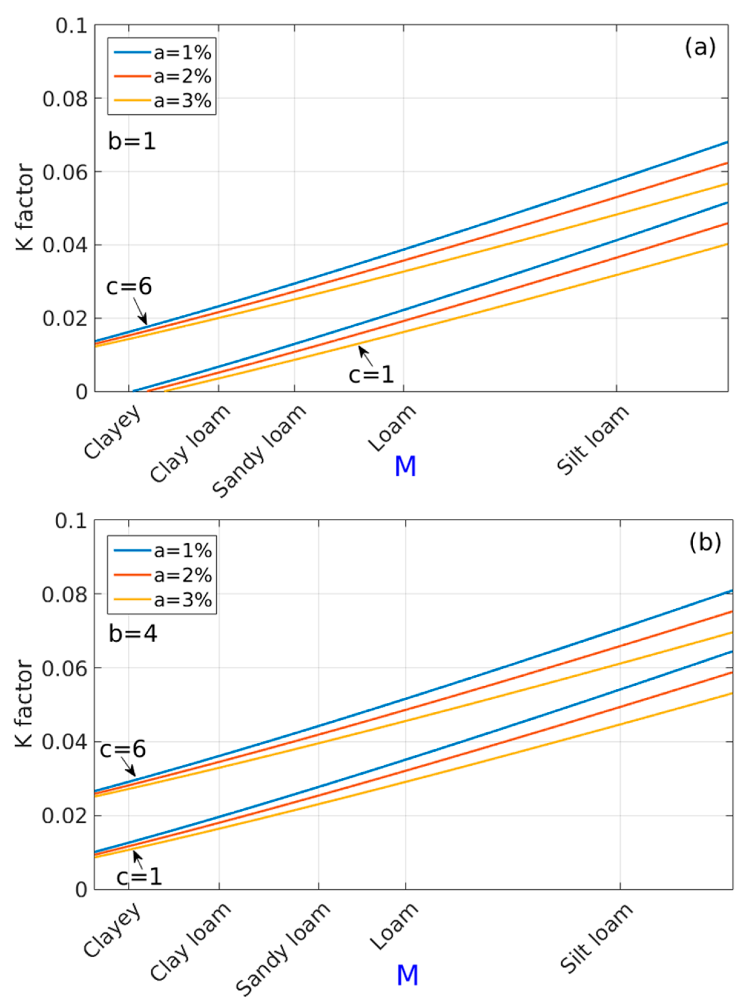
The susceptibility of singletracks to damage is strongly determined by the prevailing geophysical conditions, and particularly, by the characteristic precipitation regime, topography, and soil properties [6,9,22]. Overall, greater precipitations, steeper topography, and higher soil erodibility make singletracks more vulnerable to destruction. Among the soil properties, one of the most relevant is the texture (mechanical composition). Marion and Olive [23] reported that trail substrates classified as sandy are most susceptible to erosion, while loamy and silty soils are more durable. Soil susceptibility to erosion is determined by calculating the erodibility factor (K factor), according to Equation (1) [24]:
where: M is the particle size parameter (percent silt + percent very fine sand) × (100 − percent clay); a is the percent of soil organic matter; b is the soil-structure code (1 for very fine granular, 2 for fine granular, 3 for medium or coarse granular, and 4 for blocky, platy, or massive); and c is the profile-permeability class (1 for rapid, 2 for moderate to rapid, 3 for moderate, 4 for slow to moderate, 5 for slow, and 6 for very slow: [24]). The units of K factor are: (Mg∙ha∙h)/(ha∙MJ∙mm) [25]. For ranges of the K factor, according to M parameter of different soil textures, and giving characterizing values of a, b, and c, see Figure 1.
K factor = 2.8 × 10⁻⁷M1.14(12 − a) + 4.3 × 10⁻³(b − 2) + 3.3 × 10⁻³(c − 3)
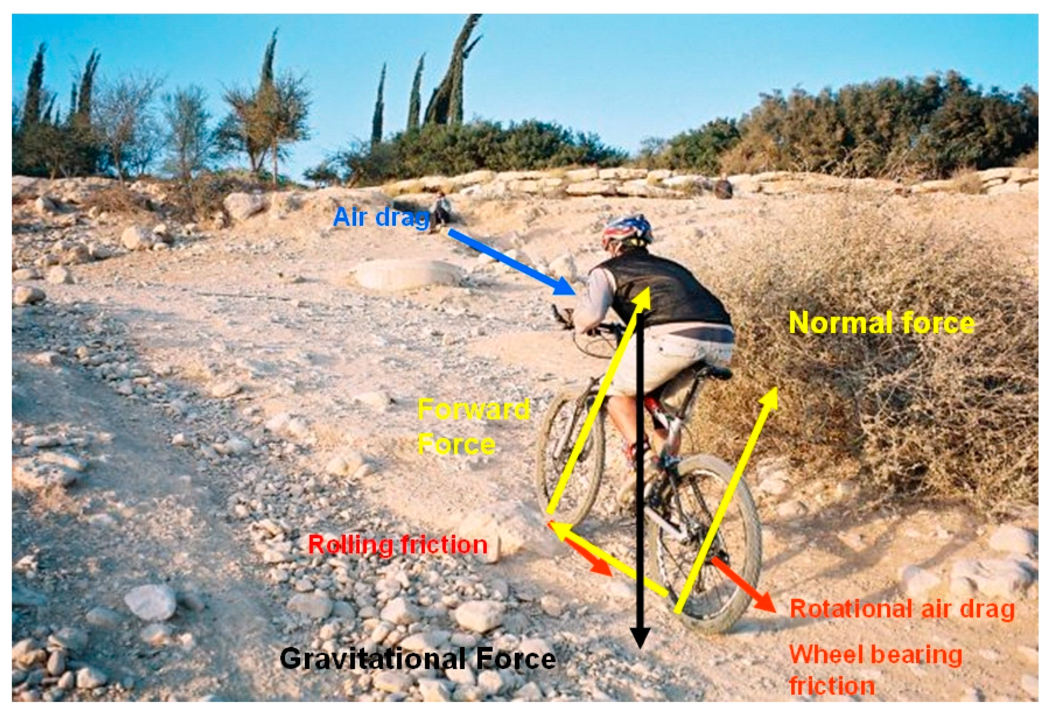
In active singletracks, shearing and wearing of the ground surface by bike tires loosen soil particles, increasing their erodibility by either water or wind. This is in accordance with Chiu and Kriwoken [14], who highlighted the potential damage to singletracks caused by the shearing stress of rotating bike tires. Yet, properly designed and well-constructed singletracks require minimal maintenance and are durable over time [23]. In this regard, knowledge on the forces imposed by bikers on the singletracks’ surface is crucial when designing trails. The singletracks’ incline is a major factor affecting the shear forces imposed by the moving bike. In uphill track sections, the rear wheel turns and creates the frictional force on the ground, which is directed backwards. According to Newton’s third law of motion, the ground exerts an equal but opposite force on the bike, which is the force that actually propels the bike. Figure 2 illustrates the forces acting on a bicycle moving uphill on a straight track. The equation of motion along the slope (Newton’s second law) of the moving bike can be described by Equation (2) [26,27]:
where: m is the combined mass of the rider and bicycle (kg); a is the biking acceleration (m∙s−2); Fp is the force pushing the bike (N); FA is the drag force of air (N); Fs is the opposing force caused by the weight component that is parallel to the slope (N); and FR is the frictional rolling force caused by the deformation of the tire and the ground (N).
ma = Fp − (FA + Fs + FR)
On a relatively smooth track, the most significant forces are FA and FR. The drag force, FA, is caused by the bike’s movement pushing air aside, forming a pocket of higher air pressure in front of the rider and a pocket of lower pressure behind the rider, as well as by the friction of the air moving along the front surface of bike and rider. This force is dependent on the biker’s velocity squared. At a velocity of 15 km∙h−1 (4.17 m∙s−1) and more, this force dominates [28]. FA can be calculated by Equation (3):
where: Kd is a coefficient that is dependent on the cross-section of the rider and bike perpendicular to the direction of movement, the bicycle frame design, and the density of air; v is the biking velocity with respect to the ground (m∙s−1); and vw is the wind speed (m∙s−1, with vw > 0 for an opposing wind).
FA = Kd (v + vw)2
The coefficient Kd can be expressed by Equation (4) [29]:
where: cd is a dimensionless air drag coefficient, which is nearly constant for regular biking velocities, and as a first approximation does not depend on v. The drag coefficient is primarily the result of eddy currents that develop in the air behind the moving bike. For example, for sport bicycles, cd = 1 when the rider sits upright, but drops to 0.9 when the rider bends over; A is the cross-section area of the bike and rider perpendicular to the direction of motion; and ρ is the air density.
Kd = 0.5cdAρ
The frictional rolling force, FR, depends on the normal forces acting on the two wheels, and can be calculated by Equation (5):
where: cr is a coefficient of the rolling friction, which depends on the tire’s air pressure, area, and cross section, the wheel diameter, and the roughness of ground surface. The rolling resistance to motion arises from deformation of both the tire and the ground surface on which it rolls, resulting in the loss of some energy to heat [30]; N is the combined normal force on the two wheels (N). It is important to note that the FR does not depend on v, while FA is dependent on the square of v. The mechanical power of a force F, acting on a body that moves in a constant velocity v, is Fv. Since the air resistance is proportional to v2, the power (invested by the rider) that is required to overcome FA increases as v3.
FR = crN
Assuming that a biker rides uphill at constant velocity, then Fp equals Fground that is applied to the ground by the rear wheel. Fground can be calculated by using Equation (6):
where: m is the combined mass of rider and bike (kg); g is the gravitational force equivalent (9.8 m∙s−2); α is the uphill track’s incline (°); cr is the coefficient of the rolling friction; Kd is a coefficient that is dependent on the cross-section of the rider and bike perpendicular to the direction of movement, the type of bicycle frame, and the density of the air; and v is the bicycle speed relative to the ground (m∙s−1).
Fground = mg(sinα + crcosα) + Kdv2
The shear stress applied by the bike’s rear tire on the ground surface (τground) can be calculated by Equation (7):
where: Fground is the force applied to the ground by the rear wheel (N); and Apatch is the rear tires’ contact patch area (m2).
τground = Fground/Apatch
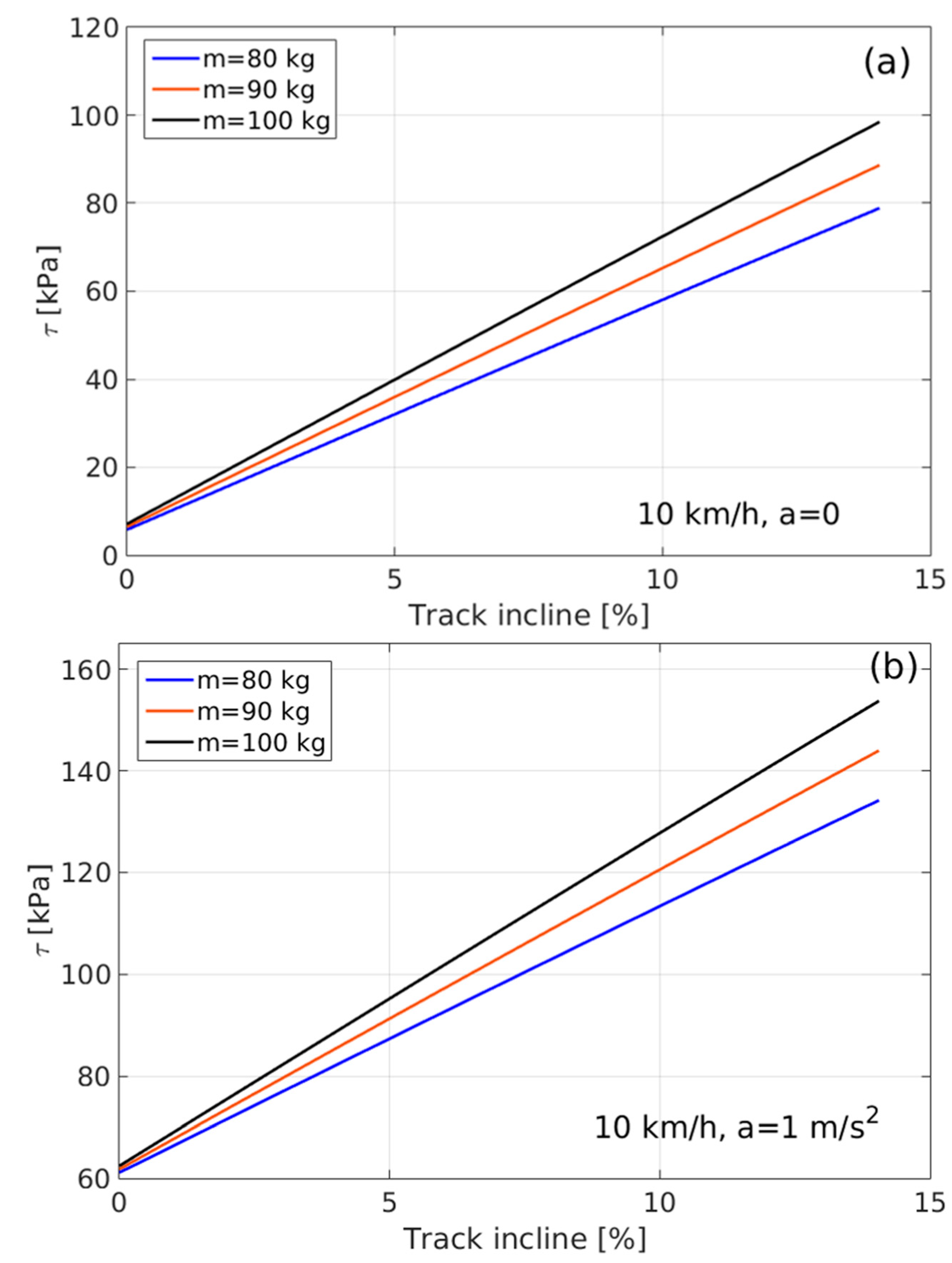
Apatch depends on the tire’s structure, the wheel diameter, the tire’s inflation, and the load it carries [30]. Usually, the rear wheel carries about twice the load of the front wheel. Figure 3 shows typical values of shear stress applied to the ground by the rear wheel when biking uphill, as a function of incline, and for different masses (combined mass of the rider and bike). The model uses typical values of parameters to estimate the shear stress applied to the ground. Overall, it shows that at a constant uphill velocity, the shear stress applied to the trail increases with increasing incline and combined mass of rider and bike (Figure 3a). Furthermore, spinning tires on uphill sections may accelerate shearing or rutting of the ground surface [6]. We assessed the impact of biking velocity on the imposed shear force for velocities ranging between 0–10 km∙h−1, and revealed insignificant differences, suggesting that biking velocity has no effect as long as it is constant. Due to physiological constraints, this situation is relevant for regular (non-electric) bikes, in which riding velocity is relatively constant or at deceleration along uphill track sections. At the same time, if the rider accelerates uphill, then Fground increases tremendously, augmenting τground. Such an effect is particularly relevant for riders of electric bikes, who can easily accelerate uphill, resulting in a considerable increase in τground imposed on the singletrack surface (Figure 3b), potentially causing greater shearing and wearing damages. Indeed, the emerging e-mountain bikes sub-sector [20,21] imposes new challenges for singletrack durability over time, requiring special attention by singletrack planners and land managers.
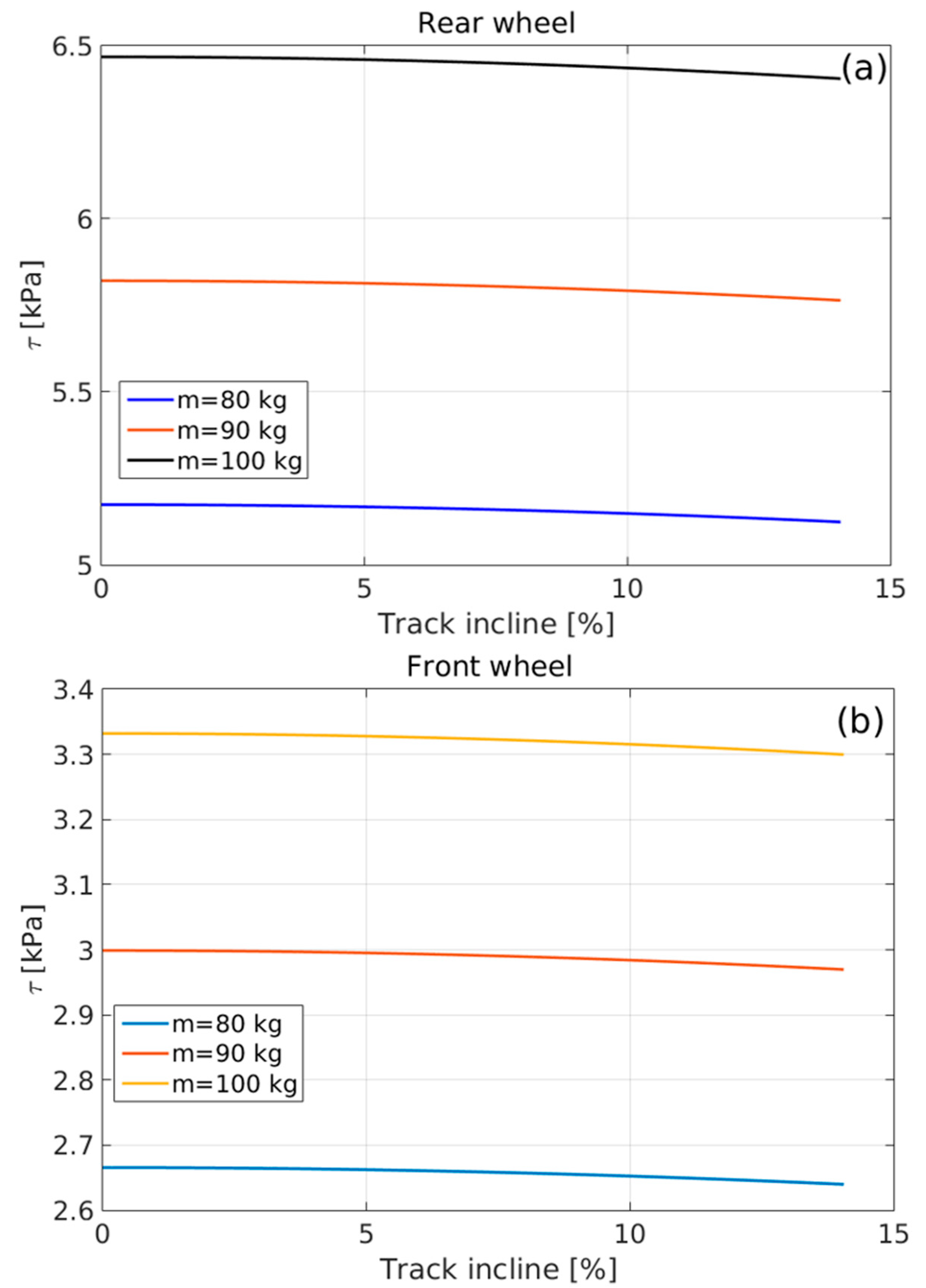
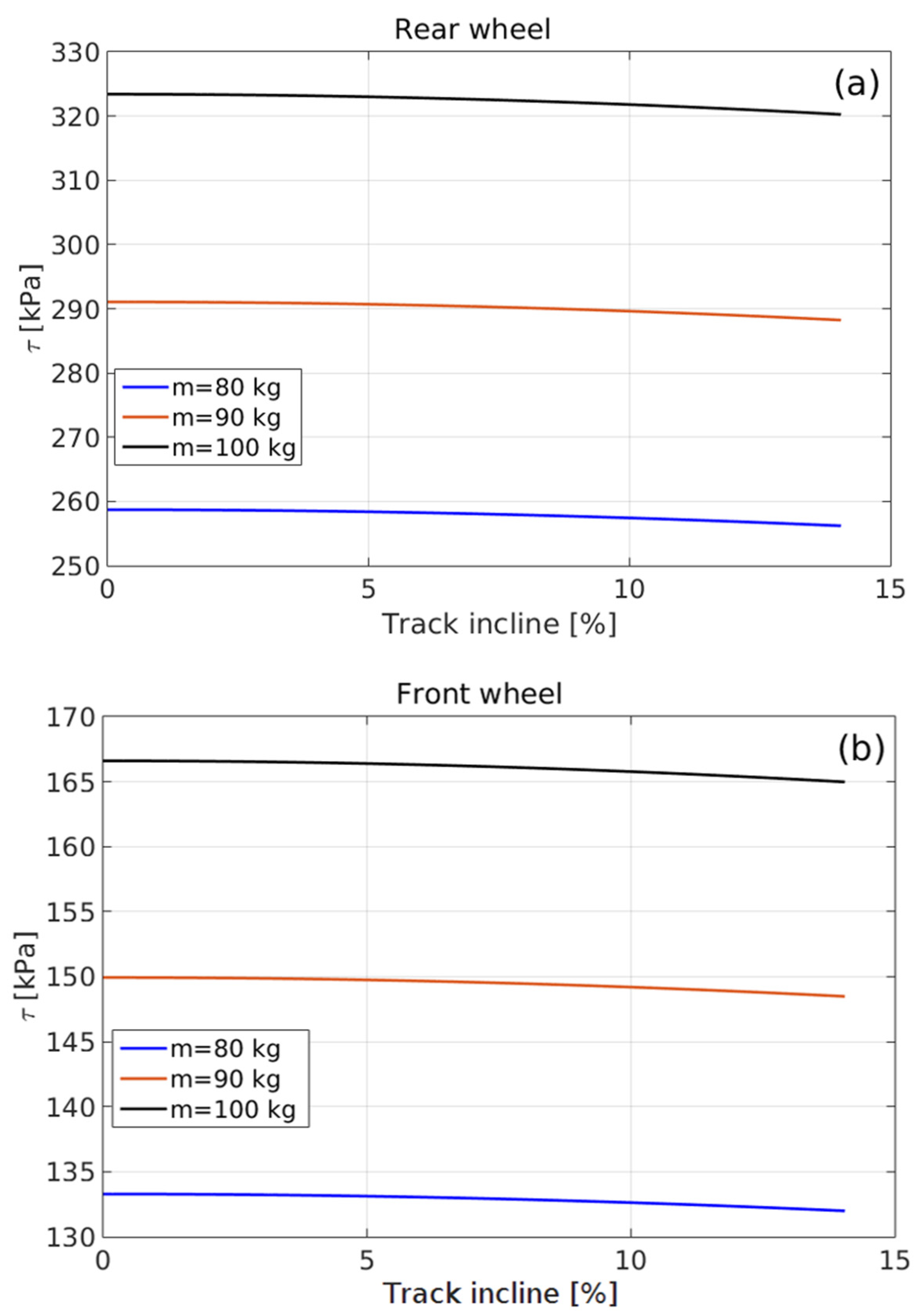
When biking along downhill track sections, as long as riding velocity is constant, the only force acting on the ground is FR, which is the rolling friction between the wheel and the ground, as given by Equation (5). Under these conditions, cr is quite low (~0.01: [31]). Figure 4 shows the shear stress applied to the ground surface by the two wheels as a function of the downhill track’s incline, and for riding at a constant velocity. Yet, upon skidding, the force applied to the ground is the kinetic friction between the wheels and the ground, as shown in Equation (8):
where: Fk is the kinetic frictional force (N); μk is the kinetic friction coefficient; N is the combined normal force on the two wheels (N); m is the combined mass of rider and bike (kg); g is the gravitational acceleration (9.8 m∙s−2); and α is the downhill track’s incline (°).
Fk = μkN = μkmgcosα
While skidding, since μk is much larger than cr, the shear stress applied to the ground surface is much greater, as shown in Figure 5. This accords with other studies, which showed that fast downhill biking with frequent hard braking imposes excess torque on the wheels and causes the skidding (‘wheeling impact’), resulting in soil shearing and track surface rutting, and ultimately increasing track destruction [5,9,14,15,22].
3. Specific Measures for Singletrack Construction
Wherever highly durable track segments are necessary to prevent their shearing or wearing under the bike wheels, ‘cementing’ of the tracks’ surface may be conducted by slightly moistening the target segments and compacting them using a manual ramming machine (Figure 6a). In highly susceptible hotspots, the tracks’ surface may need additional fortification. This can be achieved by compacting a mixture of ~5–10 cm rock fragments, clay-rich soil (sustainably obtained from the nearby surroundings), and water, to form a ~10-cm thick durable layer on the track surface (Figure 6b). This consists with Marion and Olive [23], who stressed that trails can be hardened by adding gravel to their soil, resulting in increased singletrack durability over time.
Following rainstorms, when the soil is moist, the singletrack’s surface is highly prone to compaction and deformation, exacerbating the risk of rutting by the bike tires [6,32]. This is because friction between soil particles decreases in moist conditions, making the soil more deformable [33]. This accords with previous studies, which highlighted the risk of soil structure disruption in muddy sections along singletracks [6,9]. Further, it is evident that muddy sections force bikers to bypass them and thus widen the trail. Over time, widening of such singletrack sections increases their environmental footprint, adversely affecting geo-ecosystem functioning and the sustainability of mountain biking [5,9,23]. Further, the excess soil compaction by the bike tires decreases water infiltrability, consequently increasing water overland flow [34] along the singletrack. A specific risk is imposed by the longitudinal ruts formed by tires, which may increase concentrated overland water flow along them, accelerating rill erosion [9] and possibly gully incision. At the same time, the compaction of track’s ground surface increases soil strength, decreasing its susceptibility to shear by external forces, such as wind, runoff [13,35], and bike tires [22]. Over time, the combined effect of shearing (under dry conditions) and compaction (under moist conditions) of trails’ ground surface, give the singletracks surface a concave cross-section, effectively turning them into connective water courses [13], resulting in risk of accelerated soil erosion.
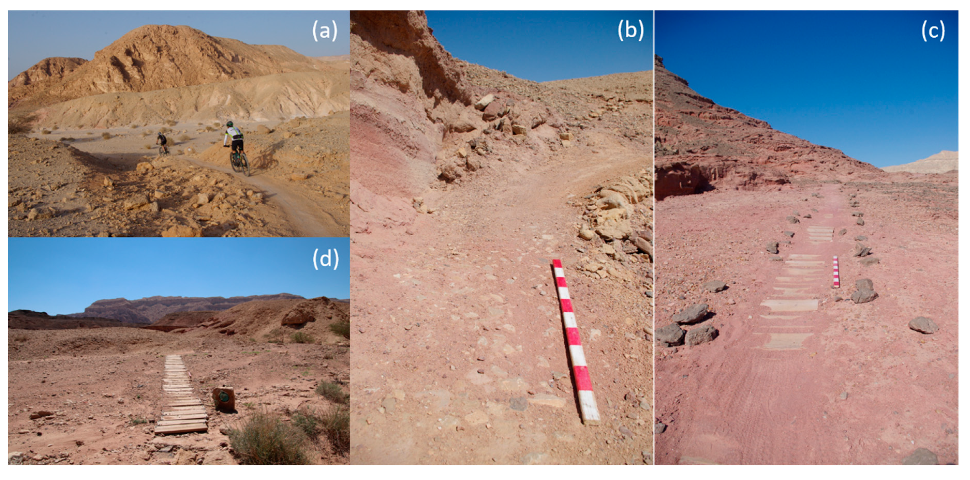
Wherever singletrack construction requires building materials, local materials should be used for both environmental and economic reasons. Specifically, local stones, which are abundant in many landforms, can easily be used to construct singletracks. Yet, in highly erodible or extremely unstable hotspots, artificial materials, such as chain-woven woodblocks, might be needed to construct short singletrack sections in hillslopes (Figure 6c) or ephemeral stream channels (Figure 6d). Being either natural or artificial, the use of these materials in hotspots is expected to decrease the shearing, rutting, and erosion of singletracks, resulting in increased durability.
Highly sheared, rutted, or eroded singletrack sections, which are unsuitable for reclamation schemes, should be closed to bike traffic to negate further degradation of their surroundings. This can be achieved by scattering local stones over the target singletrack sections. This management practice not only prevents singletrack use, it also increases the tracks’ surface roughness and negates its hydrological connectivity, augmenting on-site accumulation of water and retention of mineral and organic resources. Over time, it is expected that the materials deposited along the closed track sections will allow self-restoration of pedogenic conditions. This accords with Marion and Olive [23], who stressed the importance of slowing the velocity of runoff water by laying down small stones along trails. Yet, stones must not be extensively cleared from the source area as they act as a protective cover and decrease soil erosion.
To prevent singletracks from becoming runoff channeling courses in hillslopes, the (unintended) formation of downslope berms should be avoided. For the same reason, the tracks should not have a counter-slope side-axis, nor a leveled surface. Rather, upon establishment, a slight downslope side-incline (~5% = ~3°: [23]) should be implemented. Regardless, to prevent aeolian-deposited particles from covering tracks near sand dunes, their side-incline should be steeper than that of sand’s critical angle of repose (60–70% or 30–35°: see [36]). To stabilize the track’s outer (downslope) berm, its rim should be convexly ‘ironed’ using a manual ramming machine.
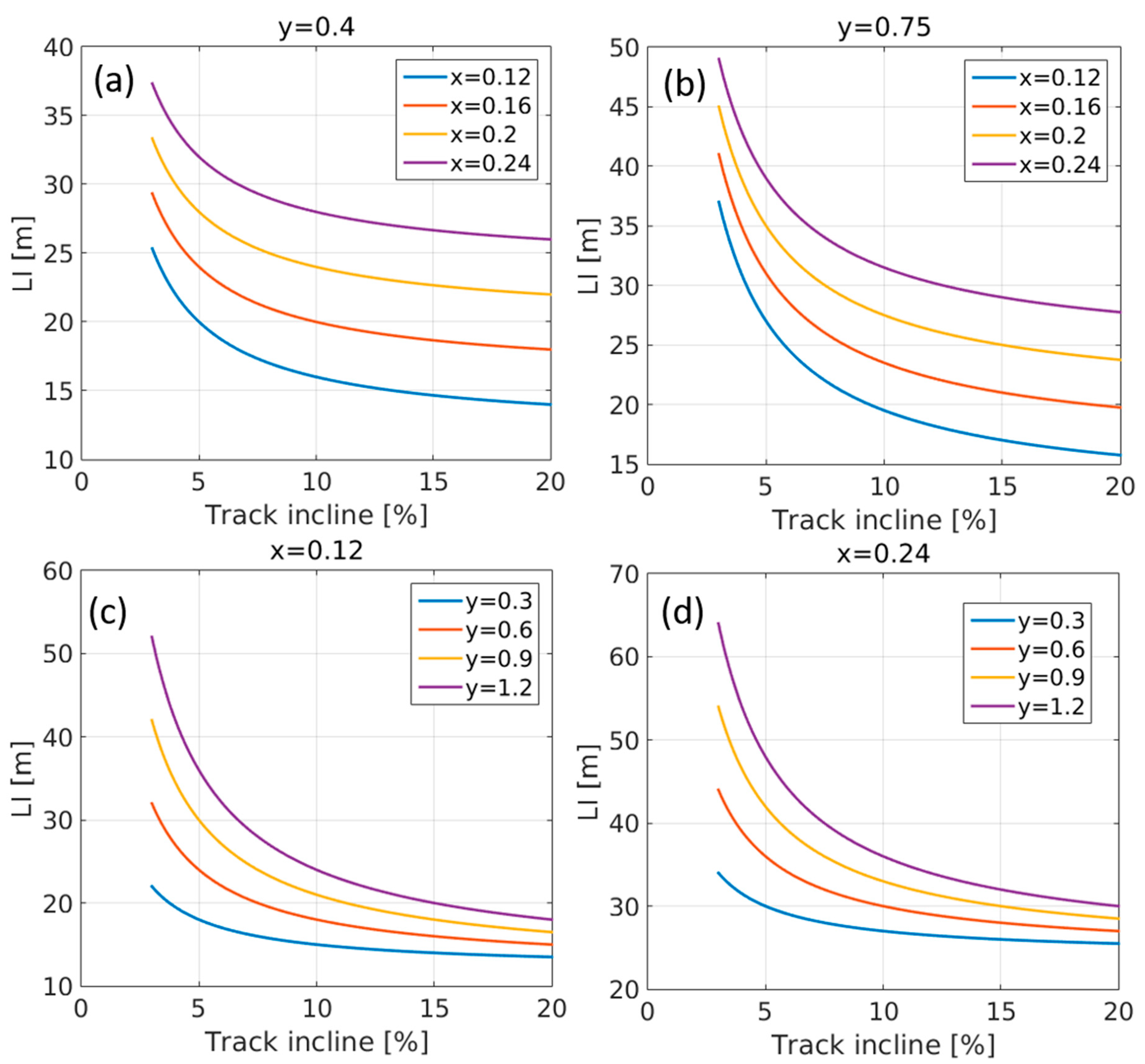
Tracks with steeper longitudinal incline are at higher risk of damage by erosional processes. For example, in southwestern United States it was demonstrated that such damages are minimal in track sections with longitudinal incline of 5%, medium for these of 5–10%, and maximal for these greater than 10% [6]. In events of negligent trail design, mudding and puddling of its surface, as well as breaching of its downslope berm, may occur. To prevent such damages, the tracks’ longitudinal axis must be transected. This can be achieved by establishing spillways (runoff outlets) at certain intervals along the track’s longitudinal axis, allowing overland flow to drain to the tracks’ downslope side (Figure 7a). This accords with other studies [9,14,23], which stressed that drainage points along singletracks act as water outlets and negate soil erosion. Additionally, downtrack of spillways, a shallow bump should be formed to completely halt runoff channeling along it. This accords with Chiu and Kriwoken [14], who studied the physical impacts of mountain biking in Tasmania, Australia, and noted that obstacles and rough track surface slow down runoff and reduce erosion. The longitudinal interval between each two adjacent spillways can be determined according to Equation (9) [37]:
where: LI is the longitudinal interval (m); x is a geographical zone coefficient (ranging between 0.12 (or less) for mesic conditions and 0.24 (or more) for xeric conditions); s is the singletrack incline (%); and y is a soil erodibility coefficient (ranging between 0.3 for the most erodible soils and 1.2 for the least erodible soils).
LI = (xs + y)(100/s)
Using this equation, we modeled the required longitudinal interval between adjacent spillways according to a wide range of combinations of x, y, and s (Figure 8). Overall, this model shows that the longitudinal interval decreases with the increase in singletrack incline, as more runoff is expected to reach the spillway. Also, the model shows that the longitudinal interval increases for xeric conditions, where less precipitation and runoff are expected.
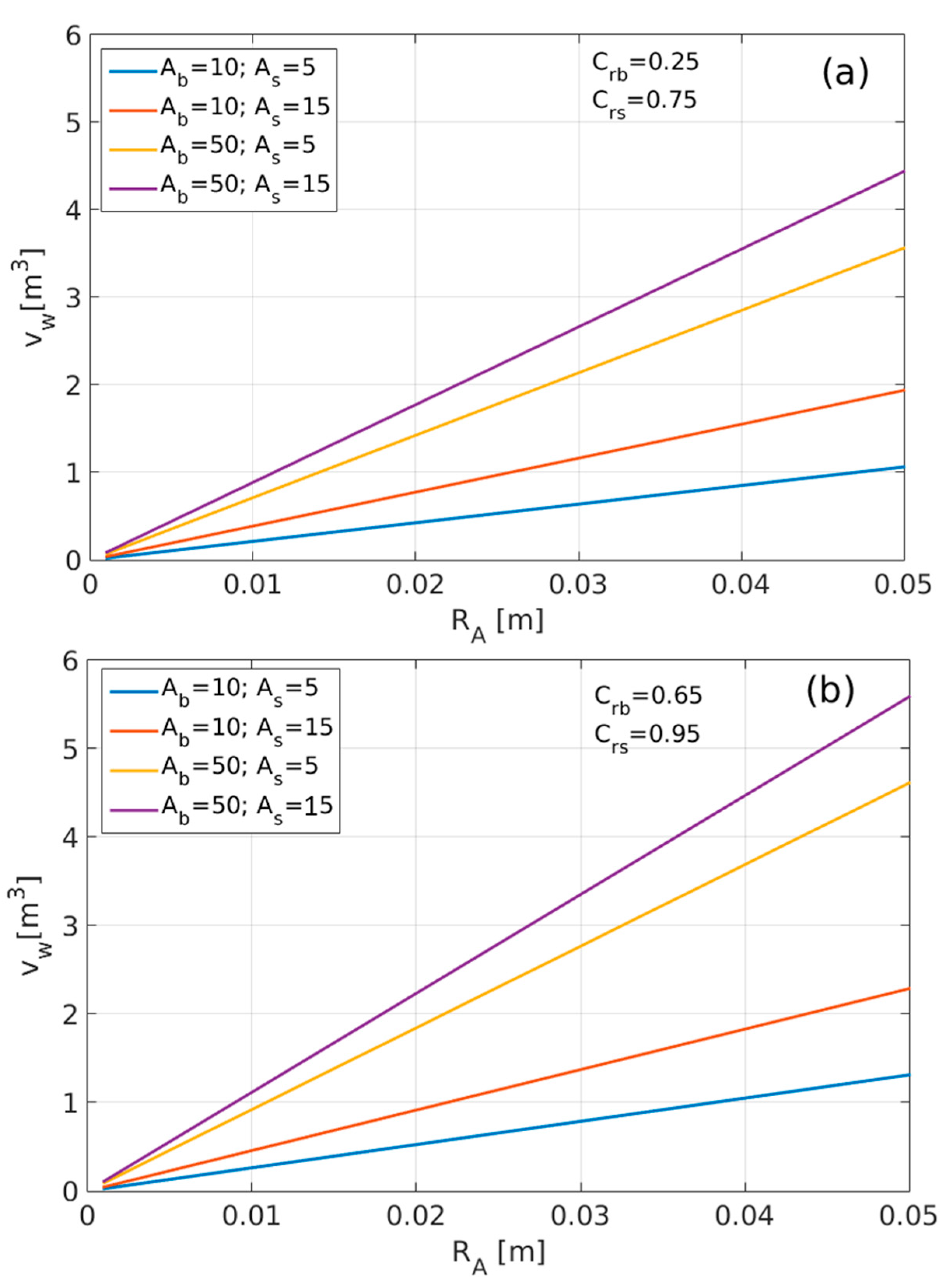
Further, in order to dissipate flow energy and prevent gully headcut retreat downslope of spillways, stones should be spread over the ground. The efforts spent on this practice can be pre-assessed by calculating the potential volume of runoff water that may possibly drain through the spillway. This can be calculated by Equation (10) (modified from [38]):
where: Vw is the volume of water that drains through the spillway during a rainfall event (m3); Ab is the area of drainage basin (excluding the uphill singletrack area: m2); Crb is the characterizing runoff coefficient of drainage basin (excluding the uphill singletrack); RA is the rainfall depth (m); As is the area of uphill singletrack interval (m2); and Crs is the characterizing runoff coefficient of the uphill singletrack interval. For ranges of Vw, according to Ab and As, and representative values of Crb, Crs, and RA, see Figure 9.
Vw = ((Ab)(CrbRA) + RA) + ((As)(CrsRA) + RA)
Regardless, in downhill tracks, hotspot sections should meander. Winding tracks force bikers to limit their speed, preventing frequent braking and the consequent skidding of bike tires, and negating the shearing of ground surface. Because of the centrifugal force imposed on the bikers, counter-slope berm should be established along the curve, reducing the need for hard braking. This counter-slope can be determined according to Equation (11):
where: Ɵ is the trail counter-slope (°); v is the biking velocity with respect to the ground (m∙s−1); µs is the static friction coefficient between the tires and the ground (ranging between 0.3 and 0.7); g is the gravitational acceleration (9.8 m∙s−2); and r is the radius of curvature (m).
tanƟ = (v2 − µsgr)/(µsv2 + gr)
Forming the counter-slope’s berm may require a large volume of soil, which should not be obtained from either intact or erodible landforms. In order to increase the strength and stability of the curve berms, stone terraces may be incorporated in these structures. Where high terraces are needed, multi-layered terraces might be required. In these structures, the particle size should gradually decrease upwards, with relatively large stones at the deeper layers, decreasing stone size in the middle layers, and fine earth material at the surface layer. The terrace’s surface soil should be compacted using a manual ramming machine (Figure 7b). In relatively steep sideslopes or in bottleneck sites, extra-stable structures might be needed. In these hotspots, ‘library’ structures made of vertically-positioned, elongated stones wedged in the soil may form high and yet stable terraces (Figure 7c).
Wherever possible, singletracks should avoid trailing along ephemeral stream channels, where difficult biking in the channel’s stone-filled bed increases the likelihood of trenching by bike tires. Where singletracks must cross channel beds, the crossing should be perpendicular to the stream bed and where the channel is narrowest. To stabilize the bed’s stone fill and negate trenching by bike tires, ‘paving’ can be achieved by embedding large flat rocks in the channel floor. Further, to fortify crossing points, large rocks should be positioned upstream of the crossing site, aimed at dissipating flash floods’ energy and reducing their erosive power. Downstream of the crossing site, loose rock check dams (see: [39]) should be established, negating gully incision and headcut retreat, and preventing the risk of crossing point collapse (Figure 7d).
Overall, while establishing singletracks, the most important issues are minimizing ground surface disturbance, and maintaining the protective cover of stones [40] and of physical, biological, or biophysical crusts [41]. As a by-product, sustaining ground surface geodiversity negates hydrological connectivity of hillslopes and reduces the erosive power of alluvial processes [42]. In turn, less runoff is expected to reach the downhill stream channels, decreasing the energy of flash floods, and lessening the magnitude of potentially devastating fluvial processes [38].
4. Concluding Remarks
Mountain biking has become a significant sector of outdoor sport, recreation, and ecotourism activities in many countries. Hence, existing singletracks receive increasing pressures, and new singletracks must be established. This conceptual study demonstrates the need to consider hydrologic and geomorphic principles while planning, establishing, and maintaining singletracks. If singletracks are properly designed, their durability is expected to increase, requiring less maintenance over time. At the same time, poorly designed and unmaintained singletracks may have an adverse impact on geo-ecosystem functioning and sustainability. Here, we demonstrate the geophysical conditions and rider characteristics that landscape designers and land managers should consider when planning nature-based, outdoor recreation opportunities.
It should be stressed that even well-designed tracks, established according to hydrologic and geomorphic principles, should be routinely inspected to monitor processes of shearing and rutting, breaching of track’s rims, and the emergence of rill and gully erosional processes. Regardless, a crucial management tool should prohibit biking after rainstorms, when soil is moist and singletracks are highly prone to deformation.
Several issues still require intensive research. For example: (i) an empirical study of the long-term durability of tracks established in different lithologies, soil types, and climatic conditions; (ii) formulating visitor impact monitoring programs, and specifically, evaluating the site-specific, optimal seasonal and annual rate, by considering the prevailing biophysical conditions, as well as the ‘average’ biker’s behavior; (iii) investigating long-term effects of singletracks on spatial distribution, productivity, and diversity of downslope/downstream vegetation; and (iv) empirically assessing the impacts of e-mountain bikes on durability of tracks over time.
Author Contributions
Conceptualization, original draft preparation, writing, and funding acquisition, I.S.; modeling, H.Y.; All authors have read and agreed to the published version of the manuscript.
Funding
The study was funded by the Economic Branch of the Hevel Eilot Regional Council. Also, general support was provided by the Ministry of Science and Technology.
Acknowledgments
The authors are grateful to Yaron Deri, Yair Sela, Rahamim Shem-Tov, Yanai Shlomi, Guy Markman, and Hanan Ginat for the assistance in fieldwork and/or the constructive discussions on mountain biking. Also, the authors gratefully acknowledge Michelle Finzi for proofreading of the manuscript. The authors thank three anonymous reviewers, whose comments considerably improved the manuscript.
Conflicts of Interest
The authors declare no conflict of interest.
References
- Winter, P.L.; Selin, S.; Cerveny, L.; Bricker, K. Outdoor recreation, nature-based tourism, and sustainability. Sustainability 2020, 12, 81. [Google Scholar] [CrossRef] [Green Version]
- Highfill, T.; Franks, C. Measuring the U.S. outdoor recreation economy, 2012–2016. J. Outdoor Recreat. Tour. 2019, 27, 100223. [Google Scholar] [CrossRef]
- Thomas, S.L.; Reed, S.E. Entrenched ties between outdoor recreation and conservation pose challenges for sustainable land management. Environ. Res. Lett. 2019, 14, 115009. [Google Scholar] [CrossRef]
- Paracchini, M.L.; Zulian, G.; Kopperoinen, L.; Maes, J.; Schägner, J.P.; Termansen, M.; Zandersen, M.; Perez-Soba, M.; Scholefield, P.A.; Bidoglio, G. Mapping cultural ecosystem services: A framework to assess the potential for outdoor recreation across the EU. Ecol. Indic. 2014, 45, 371–385. [Google Scholar] [CrossRef] [Green Version]
- Quinn, M.; Chernoff, G. Mountain Biking: A Review of the Ecological Effects. A Literature Review for Parks Canada—National Office (Visitor Experience Branch), Final Report. 2010. Available online: https://www.lib.washington.edu/msd/norestriction/b67566091.pdf (accessed on 10 November 2020).
- White, D.D.; Waskey, M.T.; Brodehl, G.P.; Foti, P.E. A comparative study of impacts to mountain bike trails in five common ecological regions of the southwestern U.S. J. Park Recreat. Adm. 2006, 24, 21–41. [Google Scholar]
- Pickering, C.M.; Hill, W.; Newsome, D.; Leung, Y.F. Comparing hiking, mountain biking and horse riding impacts on vegetation and soils in Australia and the United States of America. J. Environ. Manag. 2010, 91, 551–562. [Google Scholar] [CrossRef] [PubMed]
- Koemle, D.B.A.; Morawetz, U.B. Improving mountain bike trails in Austria: An assessment of trail preferences and benefits from trail features using choice experiments. J. Outdoor Recreat. Tour. 2016, 15, 55–65. [Google Scholar] [CrossRef]
- Cessford, G.R. Off-Road Impacts of Mountain Bikes: A Review and Discussion; Science & Research Series No. 92; New Zealand Department of Conservation: Wellington, New Zealand, 1995. Available online: https://www.imba-europe.org/sites/default/files/Off%20road%20impacts%20of%20mountain%20bikes_review%20and%20discussion.pdf (accessed on 10 November 2020).
- Thurston, E.; Reader, R.J. Impacts of experimentally applied mountain biking and hiking on vegetation and soil of a deciduous forest. Environ. Manag. 2001, 27, 397–409. [Google Scholar] [CrossRef]
- Pickering, C.; Ansong, M.; Wallace, E. Experimental assessment of weed seed attaching to a mountain bike and horse under dry conditions. J. Outdoor Recreat. Tour. 2016, 15, 66–70. [Google Scholar] [CrossRef]
- Weiss, F.; Brummer, T.J.; Pufal, G. Mountain bikes as seed dispersers and their potential socio-ecological consequences. J. Environ. Manag. 2016, 181, 326–332. [Google Scholar] [CrossRef]
- Marion, J.; Wimpey, J. Environmental Impacts of Mountain Biking: Science Review and Best Practices; USGS Patuxent Wildlife Research Center: Laurel, MD, USA, 2007. Available online: https://pubs.er.usgs.gov/publication/5211390 (accessed on 10 November 2020).
- Chiu, L.; Kriwoken, L. Managing recreational mountain biking in Wellington Park, Tasmania, Australia. Ann. Leis. Res. 2003, 6, 339–361. [Google Scholar] [CrossRef] [Green Version]
- Martin, R.H.; Butler, D.R.; Klier, J. The influence of tire size on bicycle impacts to soil and vegetation. J. Outdoor Recreat. Tour. 2018, 24, 52–58. [Google Scholar] [CrossRef]
- Wilson, J.P.; Seney, J.P. Erosional impact of hikers, horses, motorcycles, and off-road bicycles on mountain trails in Montana. Mt. Res. Dev. 1994, 14, 77–88. [Google Scholar] [CrossRef]
- Tomczyk, A.M.; Ewertowski, M.W.; White, P.C.L.; Kasprzak, L. A new framework for prioritising decisions on recreational trail management. Landsc. Urban Plan. 2017, 167, 1–13. [Google Scholar] [CrossRef]
- Chavez, D.J. Mountain Biking: Issues and Actions for USDA Forest Service Managers; Research Paper PSW-RP-226-Web; United States Department of Agriculture, Forest Service, Pacific Southwest Research Station: Albany, CA, USA, 1996.
- Symmonds, M.C.; Hammitt, W.E.; Quisenberry, V.L. Managing recreational trail environments for mountain bike user preferences. Environ. Manag. 2000, 25, 549–564. [Google Scholar] [CrossRef] [PubMed]
- Pröbstl-Haider, U.; Lund-Durlacher, D.; Antonschmidt, H.; Hödl, C. Mountain bike tourism in Austria and the Alpine region—Towards a sustainable model for multi-stakeholder product development. J. Sustain. Tour. 2018, 26, 567–582. [Google Scholar] [CrossRef]
- Schlemmer, P.; Barth, M.; Schnitzer, M. Comparing motivational patterns of e-mountain bike and common mountain bike tourists. Curr. Issues Tour. 2020, 23, 1186–1190. [Google Scholar] [CrossRef]
- US Forest Service. User Created Trail Impacts—Literature Review; USFS Red Rock District, United States Department of Agriculture: Washington, DC, USA, 2014. Available online: https://www.fs.usda.gov/Internet/FSE_DOCUMENTS/stelprd3799134.pdf (accessed on 10 November 2020).
- Marion, J.L.; Olive, N. Assessing and Understanding Trail Degradation: Results from Big South Fork National River and Recreational Area; USGS Patuxent Wildlife Research Center: Laurel, MD, USA, 2006. Available online: https://www.pwrc.usgs.gov/prodabs/pubpdfs/6612_Marion.pdf (accessed on 10 November 2020).
- Lal, R.; Elliot, W. Erodibility and erosivity. In Soil Erosion Research Methods, 2nd ed.; Lal, R., Ed.; Soil and Water Conservation Society: Ankeny, IA, USA, 1994; pp. 181–209. [Google Scholar]
- Lal, R. Erodibility and erosivity. In Soil Erosion Research Methods, 1st ed.; Lal, R., Ed.; Soil and Water Conservation Society: Ankeny, IA, USA, 1988; pp. 141–160. [Google Scholar]
- Kyle, C.R. Selecting cycling equipment. In High-Tech Cycling; Burke, E.R., Ed.; Human Kinetics: Urbana-Champaign, IL, USA, 2003; pp. 1–48. [Google Scholar]
- Wilson, D.G. Bicycling Science, 3rd ed.; The MIT Press: Cambridge, MA, USA, 2004. [Google Scholar]
- Kyle, C.R. Mechanical factors affecting the speed of a bicycle. In High-Tech Cycling; Burke, E.R., Ed.; Human Kinetics: Urbana-Champaign, IL, USA, 2003; pp. 123–136. [Google Scholar]
- Hennekam, W. The speed of a cyclist. Phys. Educ. 1990, 25, 141–146. [Google Scholar]
- Glaskin, M. Cycling Science; Ivy Press, Paper Edition: London, UK, 2019; p. 192. [Google Scholar]
- Steyn, W.J.v.d.M.; Warnich, J. Comparison of the tyre rolling resistance for different mountain bike tyre diameters and surface conditions. S. Afr. J. Res. Sport Phys. Educ. Recreat. 2014, 36, 179–193. [Google Scholar]
- Hagen, S.; Boyes, M. Affective ride experiences on mountain bike terrain. J. Outdoor Recreat. Tour. 2016, 15, 89–98. [Google Scholar] [CrossRef]
- BD2304 Appendices to SID5. Soil Compaction in England and Wales—Scoping Study to Assess Soil Compaction Affecting Upland and Lowland Grassland in England and Wales. Appendix 2: The causes of Soil Compaction. 2008. Available online: http://sciencesearch.defra.gov.uk/Default.aspx?Menu=Menu&Module=More&Location=None&Completed=0&ProjectID=14699 (accessed on 10 November 2020).
- Chong, S.K.; Cowsert, P.T. Infiltration in reclaimed mined land ameliorated with deep tillage treatments. Soil Till. Res. 1997, 44, 255–264. [Google Scholar] [CrossRef]
- Unger, P.W.; Blanco-Canqui, H. Conservation tillage. In Handbook of Soil Sciences: Resource Management and Environmental Impacts, 2nd ed.; Huang, P.M., Li, Y., Sumner, M.E., Eds.; CRC Press: Boca Raton, FL, USA, 2011; pp. 25-1–25-23. [Google Scholar]
- Al-Hashemi, H.M.B.; Al-Amoudi, O.S.B. A review on the angle of repose of granular materials. Powder Technol. 2018, 330, 397–417. [Google Scholar] [CrossRef]
- NRCS Terrace. Code 600, NHCP. United States Department of Agriculture, Natural Resources Conservation Service. 2002. Available online: File:///D:/adssc/Downloads/600_NHCP_CPS_Terrace_2019.pdf (accessed on 10 November 2020).
- Stavi, I.; Siad, S.M.; Kyriazopoulos, A.P.; Halbac-Cotoara-Zamfir, R. Water runoff harvesting systems for restoration of degraded rangelands: A review of challenges and opportunities. J. Environ. Manag. 2020, 255, 109823. [Google Scholar] [CrossRef] [PubMed]
- USDA. Check Dam Erosion Control; United States Department of Agriculture: Washington, DC, USA, 2000. Available online: https://afghanag.ucdavis.edu/irrigation-natural-resource/files/water-check-dams.pdf (accessed on 10 November 2020).
- Poesen, J.; Ingelmo-Sanchez, F.; Mucher, H. The hydrological response of soil surfaces to rainfall as affected by cover and position of rock fragments in the top layer. Earth Surf. Proc. Land 1990, 15, 653–671. [Google Scholar] [CrossRef]
- Lu, P.; Xie, X.L.; Wang, L.H.; Wu, F.Q. Effects of different spatial distributions of physical soil crusts on runoff and erosion on the Loess Plateau in China. Earth Surf. Proc. Land. 2017, 42, 2082–2089. [Google Scholar] [CrossRef]
- Stavi, I.; Rachmilevitch, S.; Hjazin, A.; Yizhaq, H. Geodiversity decreases shrub mortality and increases ecosystem tolerance to droughts and climate change. Earth Surf. Proc. Land 2018, 43, 2808–2817. [Google Scholar] [CrossRef]
Figure 1.
Modeling the erodibility factor (K factor) according to percent soil organic matter (a), soil-structure code (b), and profile-permeability class (c), and according to particle size parameter (M) representing soils with different textures. These combinations are demonstrated for b representing very fine granular (a) or blocky, platy, or massive (b) soil-structure code. The K factor units are (Mg∙ha∙h)/(ha∙MJ∙mm).

Figure 2.
The forces acting on a bicycle ascending a straight track. Note: There are two main frictional forces: the first is the rolling friction that dominates at low speeds, while the air drag dominates at high speeds.
Figure 2.
The forces acting on a bicycle ascending a straight track. Note: There are two main frictional forces: the first is the rolling friction that dominates at low speeds, while the air drag dominates at high speeds.

Figure 3.
Modeling the shear stress imposed on the singletrack surface, according to longitudinal incline and combined mass of biker and bike, at a constant riding velocity of 10 km∙h−1 (a), and at 10 km∙h−1, with an acceleration of 1 m∙s−2 (b). Parameters values: cd (air drag coefficient) = 0.7; cr (coefficient of the rolling friction) = 0.01, A (the cross-section area of the bike and rider perpendicular to the direction of motion) = 0.7 m2; ρ (tire inflation pressure) = 1.2 kg∙m3; Apatch = 1×10⁻⁴ m2; and m is the combined mass of rider and bike (kg).

Figure 4.
The shear stress applied on the ground surface by the rear (a) and front (b) wheels, as a function of the downhill track’s incline and combined mass of biker and bike, at a constant riding velocity. Note: we assume that cr = 0.01, and that two thirds of total weight of the bike and the rider are on the rear wheel.

Figure 5.
The shear stress applied on the ground surface by the rear (a) and front (b) wheels as a function of downhill track’s incline and combined mass of biker and bike, when the bike skids. Note: we assume that μk = 0.5, and that two thirds of total weight are on the rear wheel.
Figure 5.
The shear stress applied on the ground surface by the rear (a) and front (b) wheels as a function of downhill track’s incline and combined mass of biker and bike, when the bike skids. Note: we assume that μk = 0.5, and that two thirds of total weight are on the rear wheel.

Figure 6.
Pictures taken (by the manuscript’s first author) in Timna Park, southern Israel, demonstrate: (a) a ‘cemented’ singletrack section. Track ‘cementing’ was implemented by slightly moistening the track surface and compacting it by a manual ramming machine; (b) a ‘fortified’ singletrack section. Track ‘fortification’ was implemented by mixing ~5–10 cm rock fragments, clay-rich soil, and water, and compacting the mixture on the track by a manual ramming machine; (c) the chain-woven woodblock trail section on a hillslope negates shearing and rutting of singletrack surface in high-instability hotspots; and (d) the chain-woven woodblock trail section in ephemeral stream channel facilitates biking and prevents tire trenching in channel beds.

Figure 7.
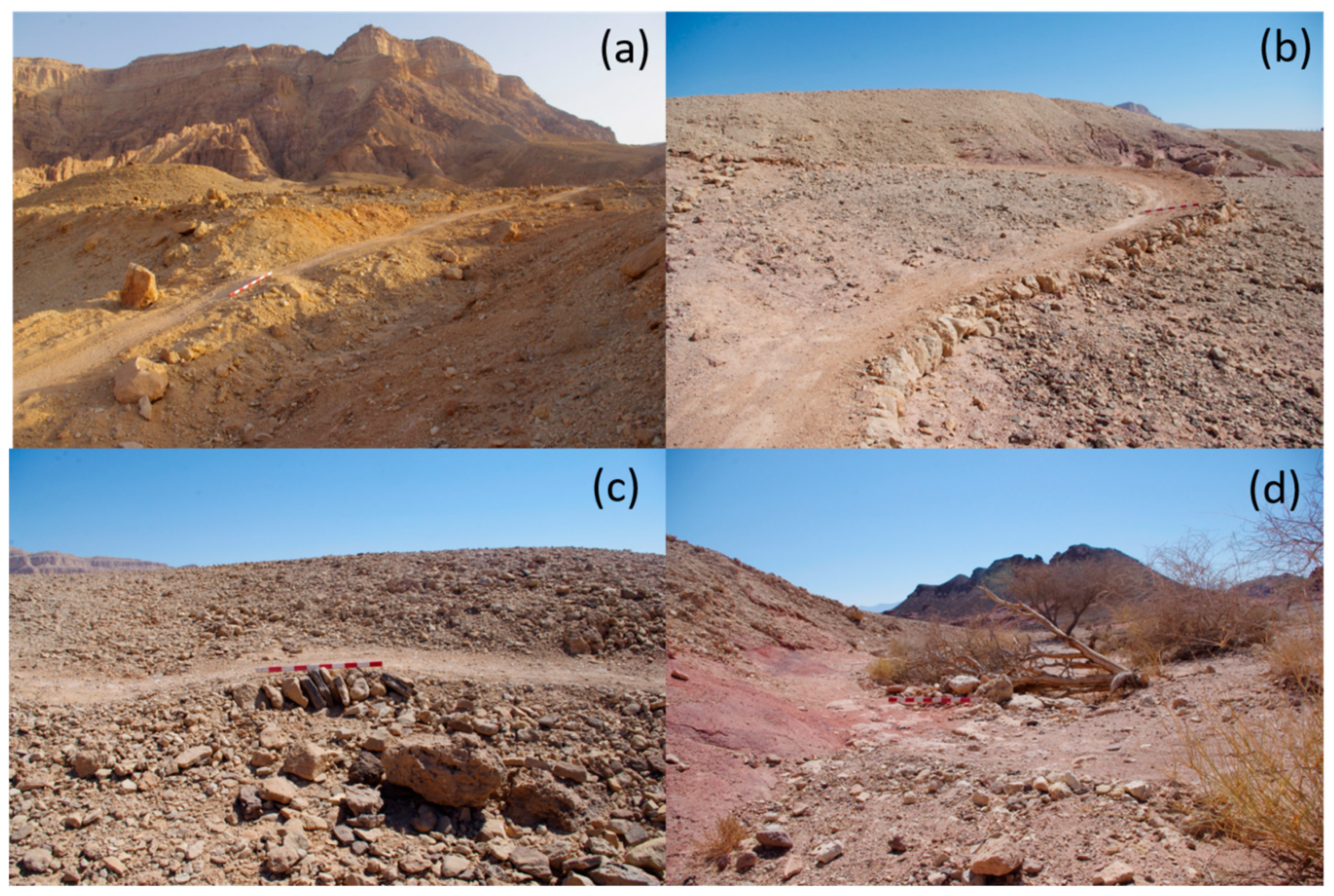
Pictures taken (by the manuscript’s first author) in Timna Park, southern Israel, demonstrate: (a) a spillway cutting the longitudinal connectivity of a singletrack. Note the shallow bump downtrack of the spillway, aimed at completely halting hydrological connectivity down the track. Also, note the stones spread downhill of spillway, aimed at dissipating flow energy and preventing gully incision; (b) downhill curving singletrack. Curve is constructed with a soil-filled berm and strengthened with a stone terrace. Note the ‘cemented’ track surface, and the berm’s counter-slope in the upper curve; (c) the ‘library’ structure, made of vertically-positioned elongated stones, wedged in the soil is effective in forming high and yet stable terraces; and (d) an ephemeral stream channel crossing point. Note the large flat rocks ‘paving’ the channel floor, aimed at preventing the bike tires’ from trenching the bed’s stone fill. The rocks positioned upstream of the crossing site dissipate flash floods’ energy, and the loose rock check dam downstream of the crossing site negates gully incision.
Figure 7.
Pictures taken (by the manuscript’s first author) in Timna Park, southern Israel, demonstrate: (a) a spillway cutting the longitudinal connectivity of a singletrack. Note the shallow bump downtrack of the spillway, aimed at completely halting hydrological connectivity down the track. Also, note the stones spread downhill of spillway, aimed at dissipating flow energy and preventing gully incision; (b) downhill curving singletrack. Curve is constructed with a soil-filled berm and strengthened with a stone terrace. Note the ‘cemented’ track surface, and the berm’s counter-slope in the upper curve; (c) the ‘library’ structure, made of vertically-positioned elongated stones, wedged in the soil is effective in forming high and yet stable terraces; and (d) an ephemeral stream channel crossing point. Note the large flat rocks ‘paving’ the channel floor, aimed at preventing the bike tires’ from trenching the bed’s stone fill. The rocks positioned upstream of the crossing site dissipate flash floods’ energy, and the loose rock check dam downstream of the crossing site negates gully incision.

Figure 8.
Modeling the length of longitudinal interval between successive spillways (LI) as a function of singletrack incline, according to geographical zone coefficient (x: ranges between 0.12 (or less) for mesic conditions and 0.24 (or more) for xeric conditions), and soil erodibility coefficient (y: ranges between 0.3 for most erodible soils and 1.2 for least erodible soils). LI for low-modestly erodible soils (a); LI for modestly-high erodible soils (b); LI for relatively mesic conditions (c); and LI for relatively xeric conditions (d).

Figure 9.
Modeling the volume of runoff water that drains through a spillway (Vw: m3), according to area of drainage basin (Ab: m2), area of uphill singletrack interval (As: m2), runoff coefficient of drainage basin (Crb), runoff coefficient of uphill singletrack interval (Crs), and characteristic rainfall depths (RA: m), for combinations of lowest (a) and highest (b) values of Crb and Crs.

Publisher’s Note: MDPI stays neutral with regard to jurisdictional claims in published maps and institutional affiliations. |
© 2020 by the authors. Licensee MDPI, Basel, Switzerland. This article is an open access article distributed under the terms and conditions of the Creative Commons Attribution (CC BY) license (http://creativecommons.org/licenses/by/4.0/).
Share and Cite
MDPI and ACS Style
Stavi, I.; Yizhaq, H. Applying Geomorphic Principles in the Design of Mountain Biking Singletracks: Conceptual Analysis and Mathematical Modeling. Land 2020, 9, 442. https://0-doi-org.brum.beds.ac.uk/10.3390/land9110442
AMA Style
Stavi I, Yizhaq H. Applying Geomorphic Principles in the Design of Mountain Biking Singletracks: Conceptual Analysis and Mathematical Modeling. Land. 2020; 9(11):442. https://0-doi-org.brum.beds.ac.uk/10.3390/land9110442
Chicago/Turabian StyleStavi, Ilan, and Hezi Yizhaq. 2020. "Applying Geomorphic Principles in the Design of Mountain Biking Singletracks: Conceptual Analysis and Mathematical Modeling" Land 9, no. 11: 442. https://0-doi-org.brum.beds.ac.uk/10.3390/land9110442
Note that from the first issue of 2016, this journal uses article numbers instead of page numbers. See further details here.