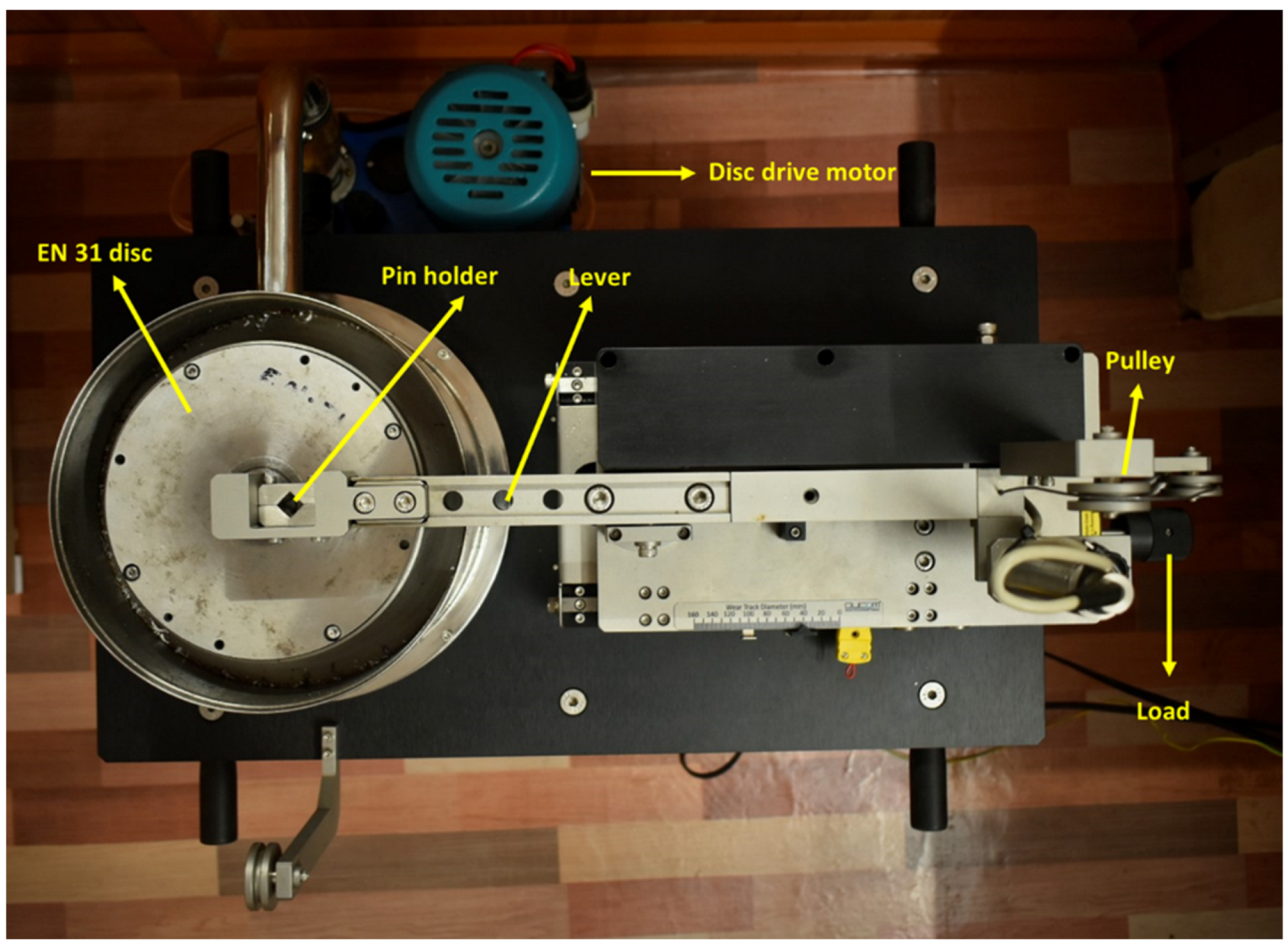
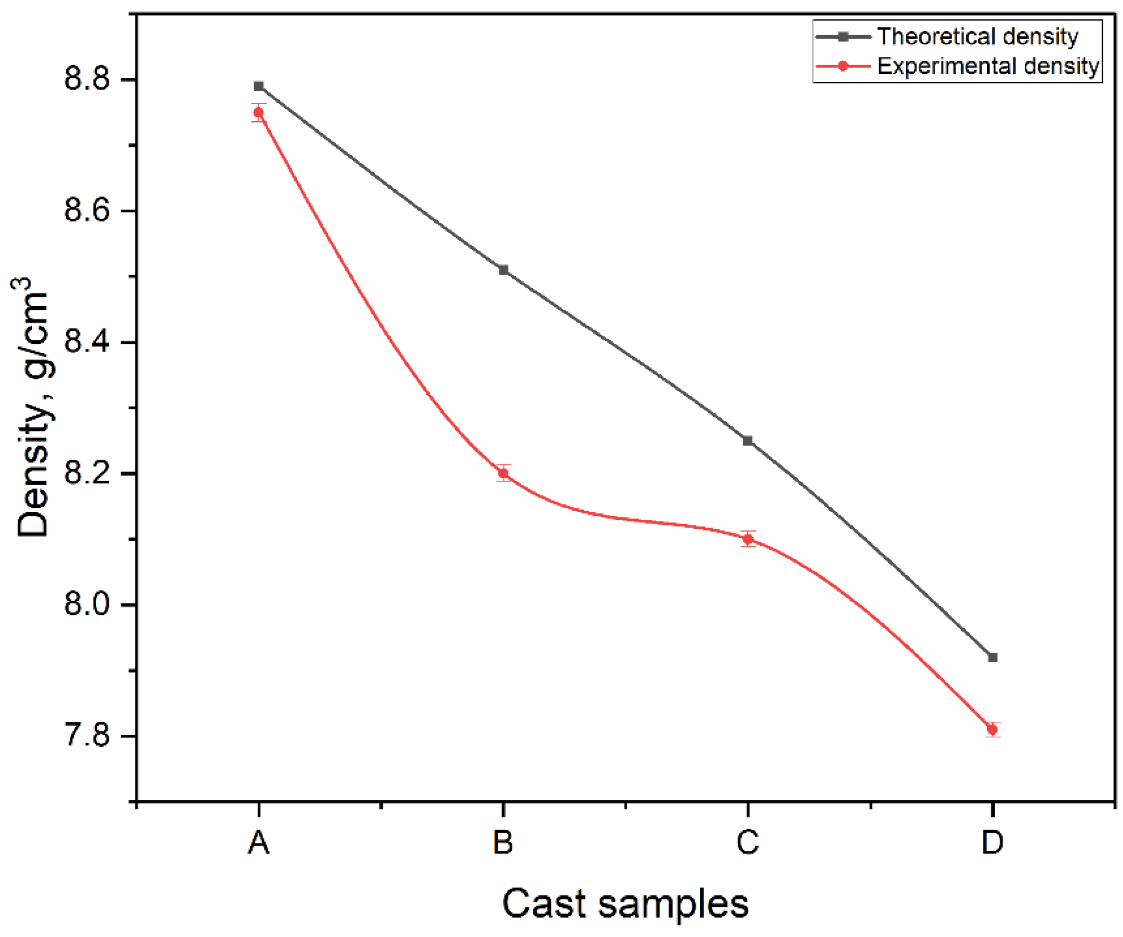
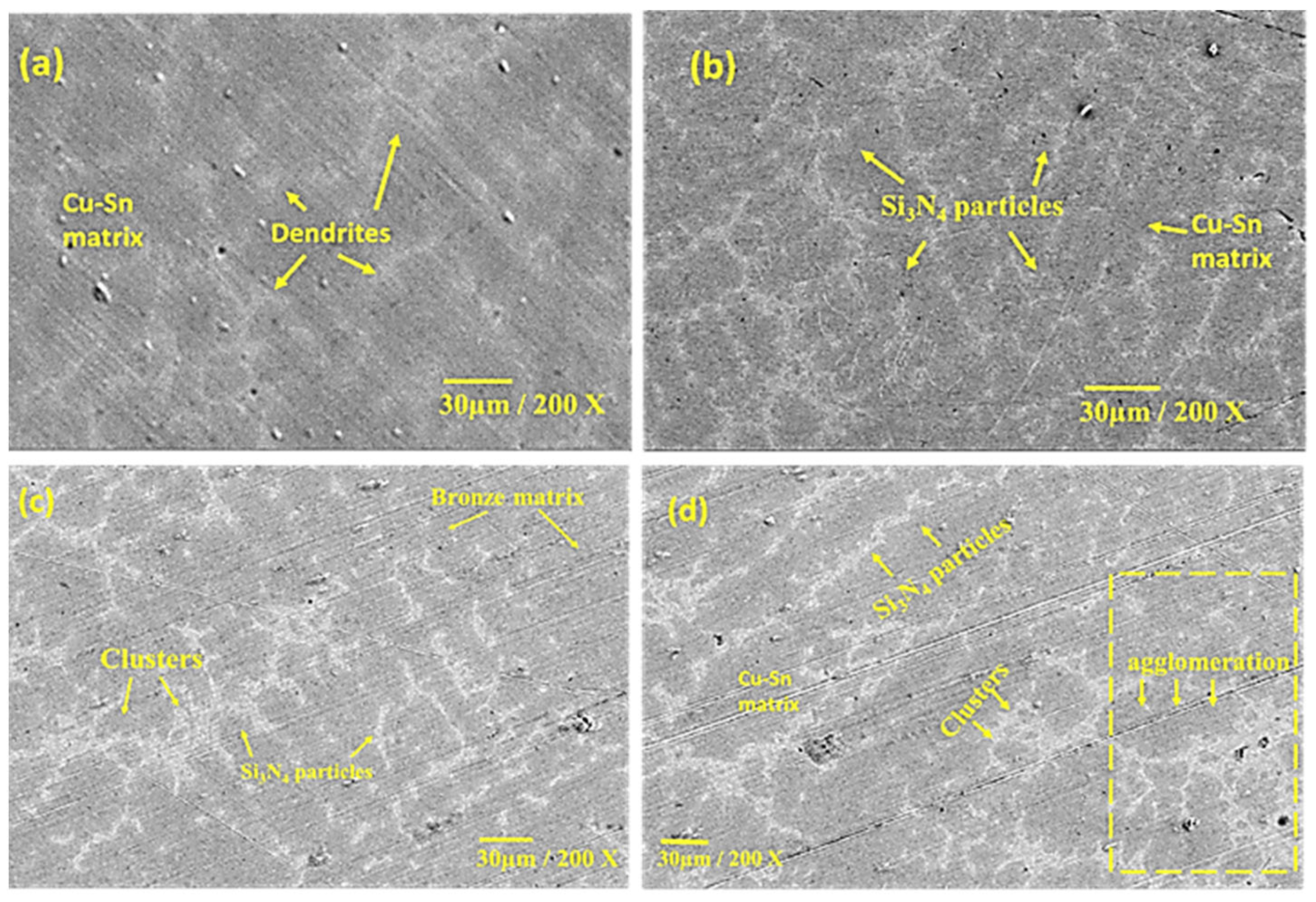
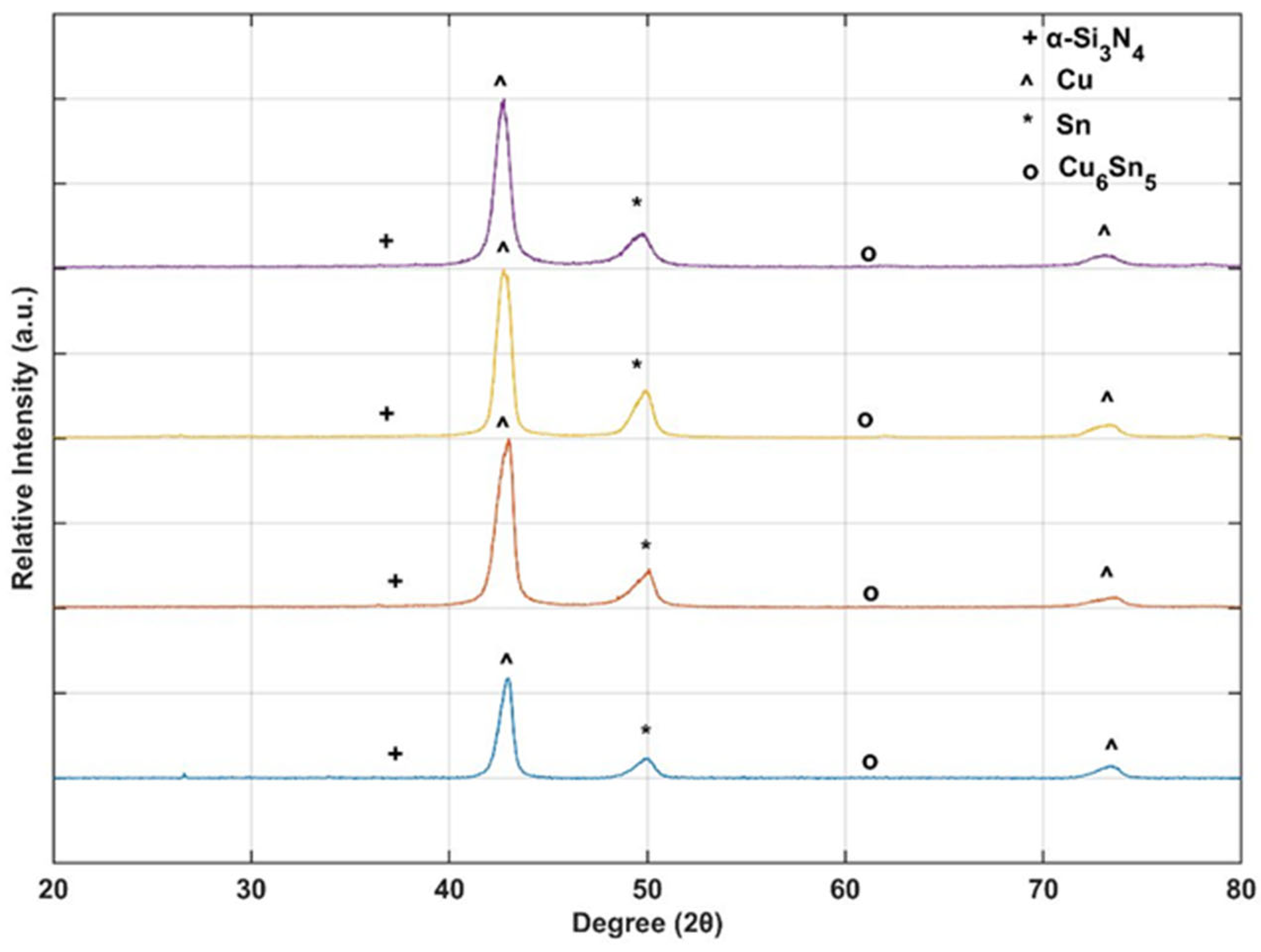
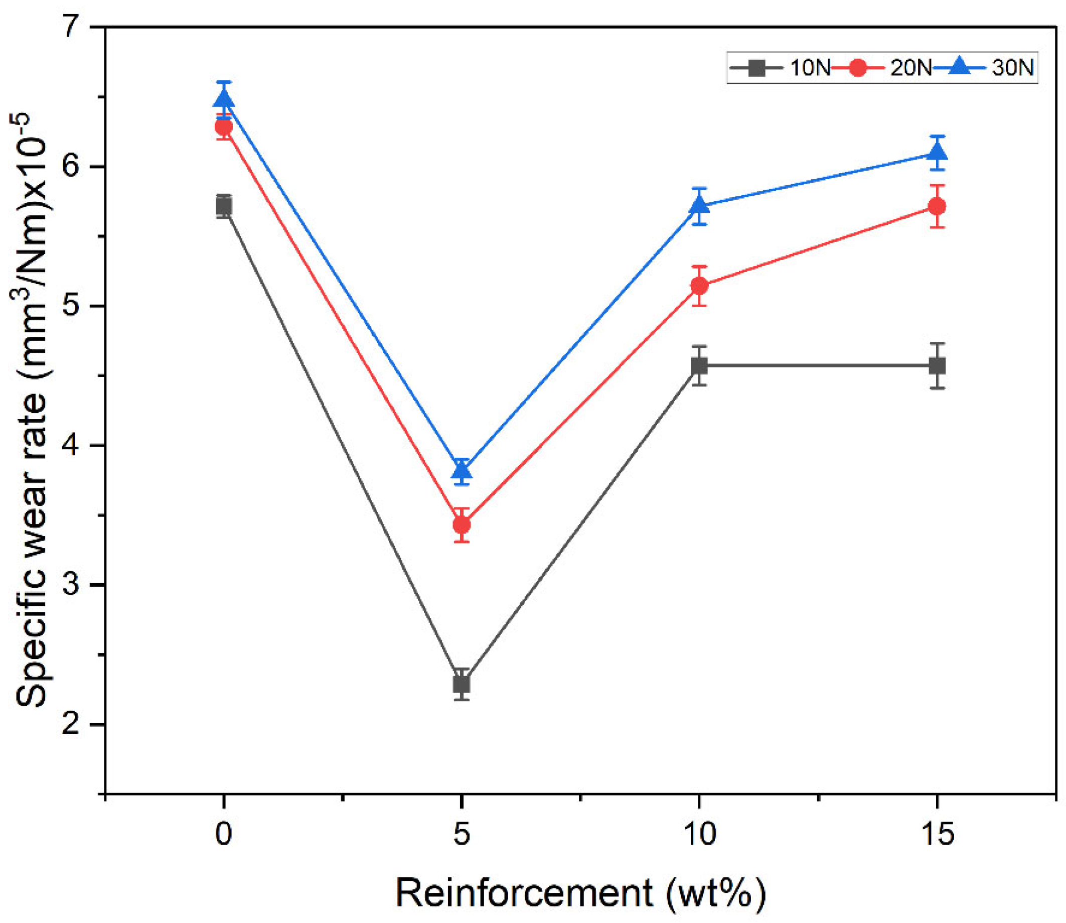
Article

Influence of Si3N4 on the Dry Sliding Wear Characteristics of Stir-Cast Cu-10Sn/xSi3N4 Metal Matrix Composite for Bearing Applications

by
Sooraj Satheesh
1,
Gokul Krishna Gopakumar Priya
1,
Govind Venugopal
1,
Anuranjan Anil
1,
Jayakrishna Ajithkumar Jayasree
1,
Anandhan Ajan Vishnu
1,
Karthik Venkitraman Shankar
1,* and
Anil Kumar
2,*
1
Department of Mechanical Engineering, Amrita Vishwa Vidyapeetham, Amritapuri 690525, India
2
Department of Mechanical Engineering, Kamla Nehru Institute of Technology, Sultanpur 228118, India
*
Authors to whom correspondence should be addressed.
Submission received: 22 November 2022 / Accepted: 29 November 2022 / Published: 5 December 2022
(This article belongs to the Special Issue Friction and Wear in Composite Materials)

Abstract

:
Bronze metal matrix composites (MMCs) are futuristic materials that may find applications in automobile, aviation, and marine industries, specifically for propellers in submarines, bearings, and bushings for defence purposes. The present investigation studied the effect of Si3N4 (5, 10, 15 wt%) ceramic particles on the physical, metallurgical, and tribological behaviour of Cu-10Sn/Si3N4 MMCs. Cast rods of three composites and a base alloy were fabricated using the liquid metallurgy route. The microstructural characterisation for the cast samples was conducted using FESEM (Field Emission Scanning Electron Microscope), EDS (Energy Dispersive Spectroscopy), XRD (X-ray diffraction), and TEM (Transmission Electron Microscope), which revealed that the Cu-10Sn alloy reinforced with 5 wt% of Si3N4 had homogeneous distribution and perfect bonding of the Si3N4 with the bronze MMC. The dry sliding wear test was performed by varying parameters such as the applied load (10, 20, 30 N) and sliding velocity (1, 2, 3 m/s). The specific wear rate (SWR) increased against an increased load. However, the SWR and coefficient of friction decreased and then increased against an increasing sliding velocity due to tribolayer formation. The primary wear mechanism observed at low and high loads was severe delamination. In contrast, the wear mechanism was adhesion wear at high and low velocities. Amongst the researched samples, Cu-10Sn/5 wt% Si3N4 composites revealed the least SWR at a load of 10 N and sliding velocity of 2 m/s and hence can be recommended for manufacturing bearings and bushings in the automobile and defence industry.

1. Introduction

Advanced research paradigms and experimental analogies have evolved conventional monolithic materials to reinforced composite materials, which have more desirable properties than monolithic ones. Traditionally used monolithic materials often struggled with limitations in properties such as thermal conductivity, electrical conductivity, resistance to wear, fatigue strength, and creep resistance [1]. Reinforced materials, such as metal matrix composites (MMCs), combine two or more different materials and tend to cover up these limitations with tremendous improvements in properties. These MMCs can yield the desired properties with utmost accuracy when combined meticulously. This draws in the broad interest of researchers toward the possibility of reinforcements and the development of composites from existing alloys [2].
The usage of particulate reinforcements over the fibre or flake types increases the mechanical and tribological properties of MMCs, thereby making them the best alternative for unreinforced materials [3]. The metal matrix composites made from copper and its alloys are extensively used for commercial purposes [4]. For automobile components such as clutches, sleeves, and bearings, where friction is very high, copper-based MMCs are used to tackle the problem of extensive wear [5,6]. Copper is thus a commercially demanding matrix material for composite fabrication. However, due to the poor mechanical performance of copper, it is not used in applications where strength is a crucial requirement [7]. Research has made it possible to reverse this drawback by reinforcing it with excellent and hard ceramic materials (carbides, nitrides, borides, etc.) [8].
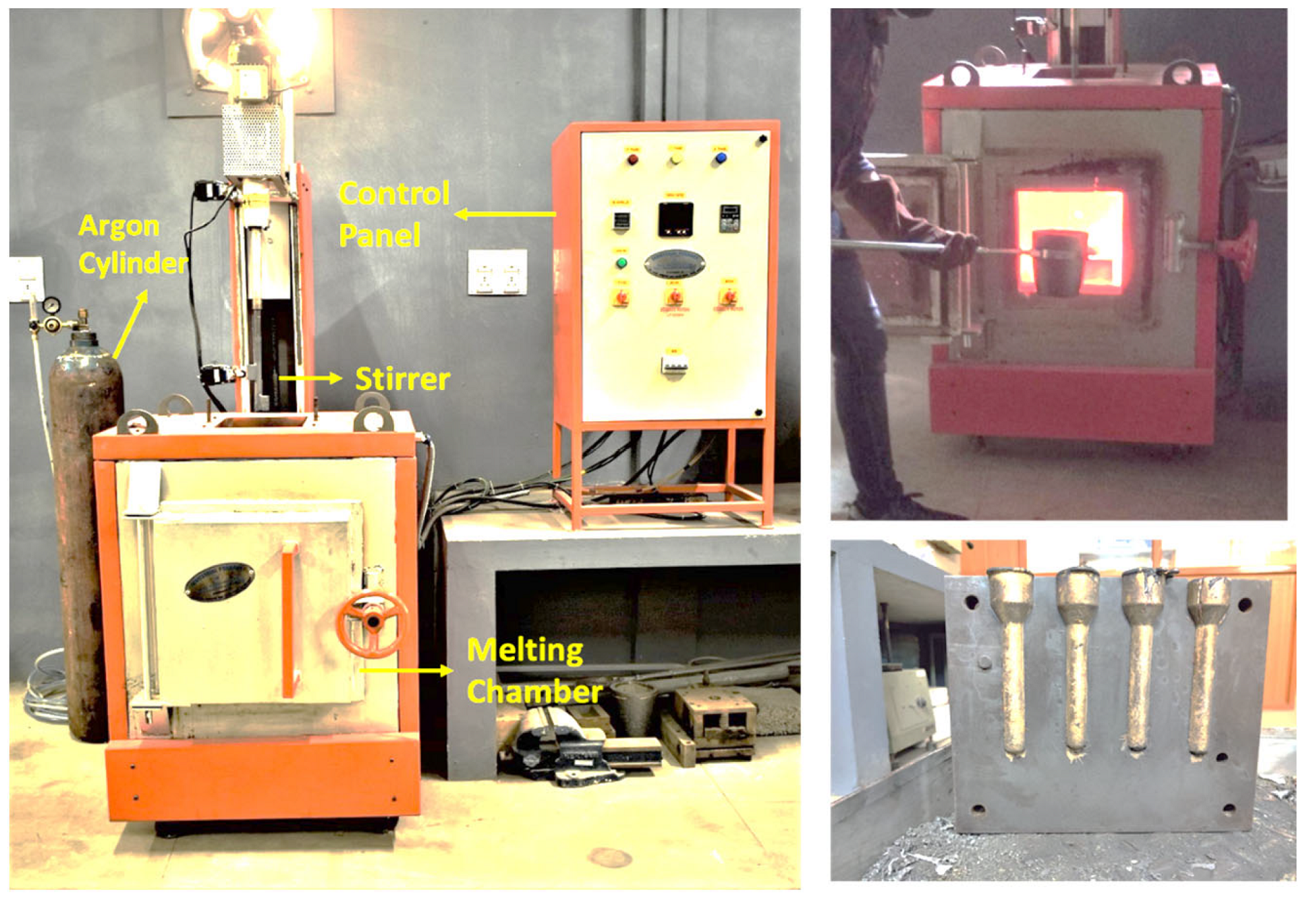
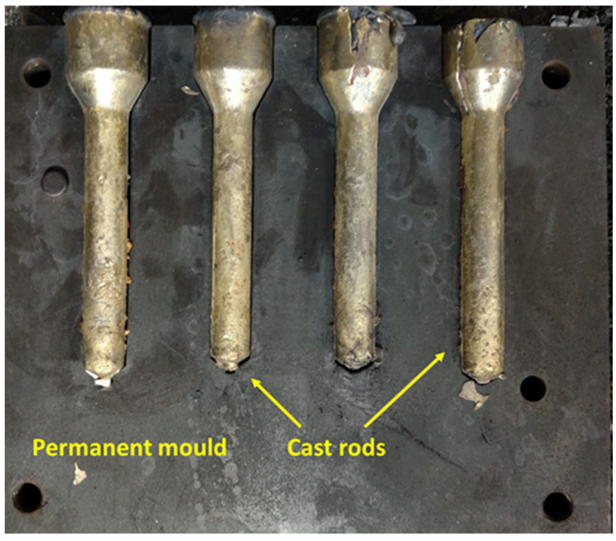
Stir casting will enhance the interfacial bonding between the reinforcement and the matrix metal, imparting many advantages [9]. These include improved design flexibility and simplicity while fabricating compared with other processes such as squeeze casting, electrochemical processing, and powder metallurgy [10]. Wettability is a prime factor determining interfacial bonding strength between reinforcement and matrix material [11]. Stir casting with the help of a mechanical stirrer ensures excellent and uniform dispersion of the reinforcement, thereby providing the advantage of wettability. Powder metallurgy is also a fantastic route to fabricate composites from copper alloys efficiently, but the cost of the entire process limits its use [12].
Considering the arena of metal matrix composites, pure copper is not that reliable to be used as a matrix material. The addition of Cr in Cu-alloys improved the corrosion resistance [13]. When alloyed with Sn, copper requires high-end lubricants to aid its wear resistance. However, it was found that fabricating a Cu-Sn alloy with a suitable reinforcement through up-drawing continuous casting reveals excellent wear resistance with minimal lubrication requirement [14]. This alloying of Sn to Cu improves the tensile and compressive strength. For instance, they can be of great use in making bearings [15,16]. When subjected to high contact pressures, bearings are known to develop cracks. The propagation of such damages can be efficiently restricted with improved tensile and compressive strength [17].
Many studies have spotted a staggering increase in mechanical strength, corrosion resistance, and creep resistance in the Cu matrix when reinforced with several ceramic particles. These include TiC, Cr2O3, Al2O3, TiO2, B4C, carbon nanotubes, SiC, and graphite [18,19]. A copper matrix, reinforced with specific reinforcements such as Al2O3, graphite, and graphene nanotubes, has portrayed a stringent ability to restrict plastic flow and prevent crack propagation [20,21]. They also increase the transition period from mild to severe wear [22,23]. As reinforcement, silicon nitrate (Si3N4)’s new addition of ceramic particles has caught the interest of scientists due to its gleaming mechanical properties. Since it is a recent development, the documented evidence regarding the effects of Si3N4 on copper matrix and the resulting composite’s tribology is limited. The researchers found that adding Si3N4 further increases the properties to a new level by developing excellent wear and corrosion resistance and the ability to withstand high-temperature shocks [24]. The copper-based composite with Si3N
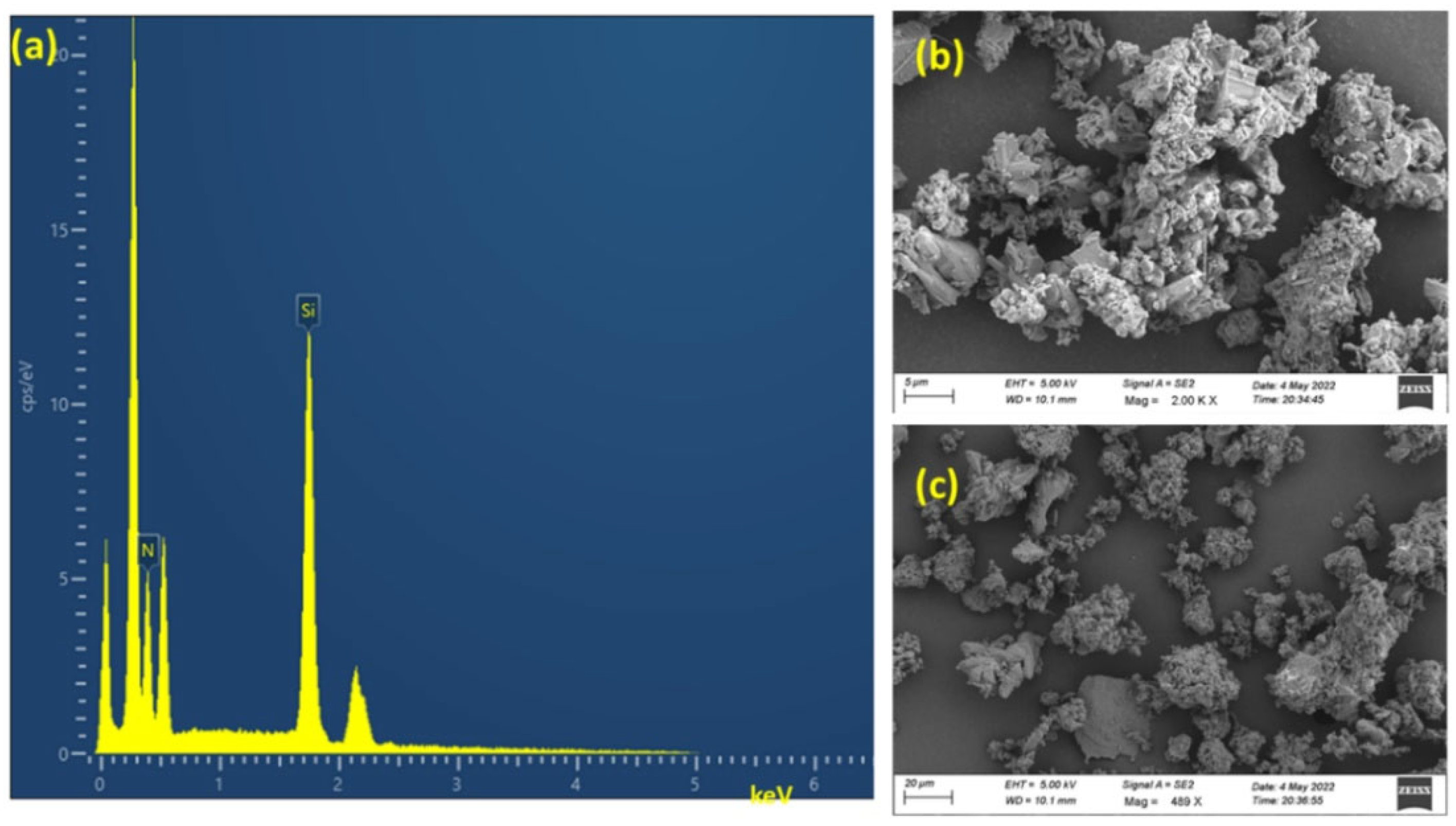
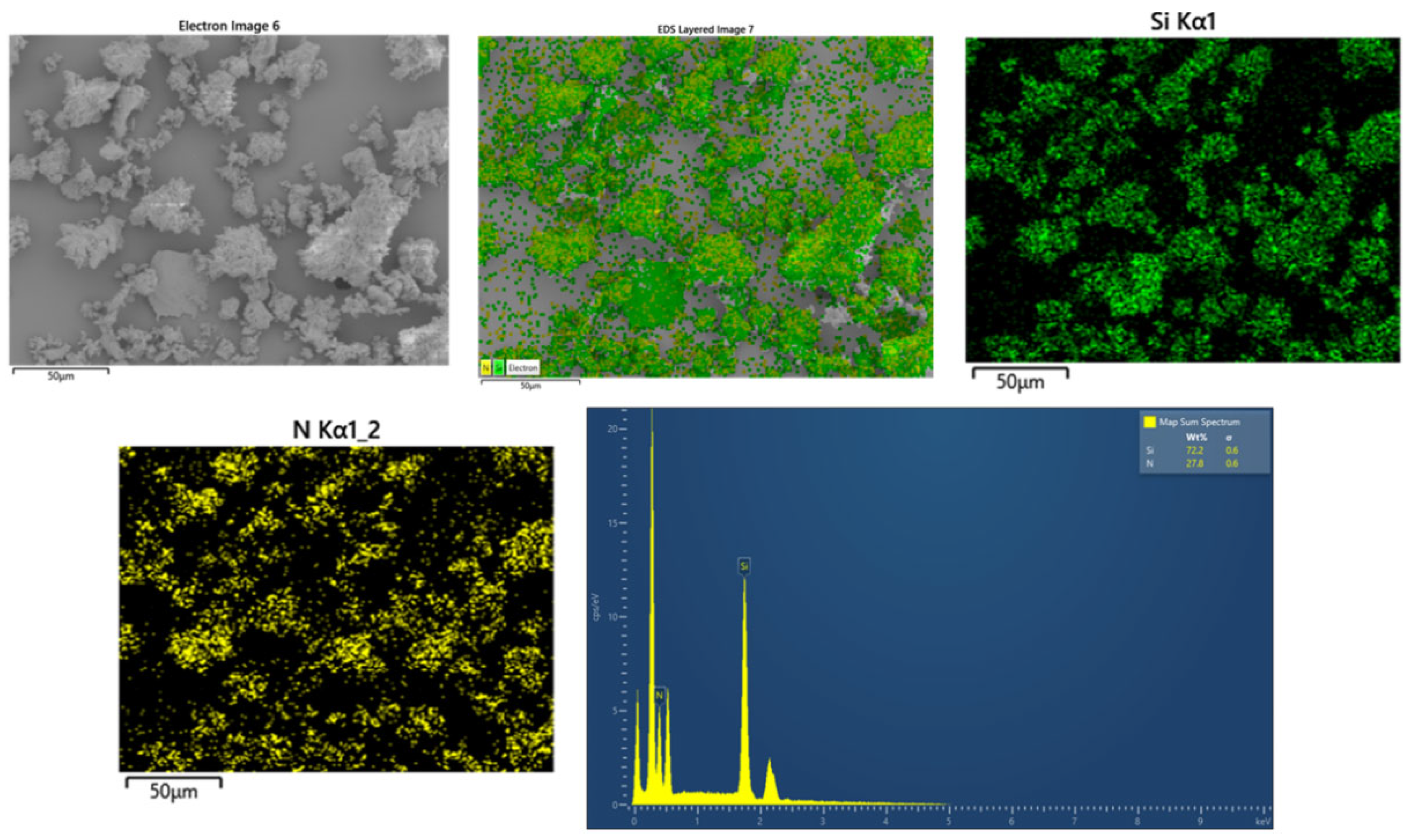
4 reinforcements in varying weight percentages is produced using the stir-casting method.
Studies on the copper alloys obtained by combining two alloying elements with copper as a base metal has depicted higher corrosion resistance than those with a single alloying element [10]. Hence, the Cu-Ni-Sn system has gained good popularity. Nevertheless, over time, the use of Ni has started to give the manufacturers and users a tricky time regarding the cost, as nickel is comparatively expensive. As a better alternative, copper alloys with tin as the alloying element is created, which are then fabricated into a composite material by reinforcing the alloy with Si3N4 (Cu-Sn/Si3N4). This composite thus binds and unveils an array of advantages and properties at a feasible cost. The Si3N4 is an inorganic ceramic material that does not shrink during processes such as sintering. The significant characteristics of Si3N4 include its high strength and low density (ρ = 3.17 g/cm3). It has strong resistance to wear and corrosion, making it an ideal composition in journal bearings, bushings, gas turbine blades, mechanical seal rings, and other such components. The crystal structure of α–Si3N4 was determined to be a hexagonal crystal structure from the studies of Hardie and Jack [25]. When considering the bearing application, the Zn-Al alloy matrix finds extensive use in the current industrial scenario. However, researchers have cited that a strong reason for this widespread use is its low cost and easy availability. On the other hand, bearings based on copper alloy composites have shown excellent reliability under heavy loads, slow speeds, and minimum lubrication conditions. The decreased abundance and expense of copper strongly restrict its widespread use. Investigations on the wear behaviours of these alloys have shown that bronze matrix-based composites have greater wear resistance than Zn-Al-based composites. This is because they are less prone to wear mechanisms such as adhesion than their Zn-Al counterparts. Thus, over Zn-Al-based composites, bronze-based composites are very useful in heavy-duty applications and at high fatigue conditions [26,27].
Furthermore, various other experimental results have proved that even when subjected to rigorous heating followed by rapid cooling multiple times, the Si3N4 material will not crack [28,29]. Recently, Govind et al. investigated the impact of varying wt% of Si3N4 (5, 10, 15) on the mechanical and physical properties of Cu-10Sn alloys. The study revealed that the composite with 5 wt% of Si3N4 shows optimal properties [30]. This divulges the incredible resistance of Si3N4 towards thermal shocks and its wear resistance, making it very suitable for tribological applications. Despite its drawback of poor thermal conductivity compared with other ceramic reinforcements, it is still preferred for industrial applications because of its explicit ability to withstand thermal shocks and excellent wear resistance. Nickel–aluminium bronze (NAB) is an alloy widely used to manufacture ship valves and propellers for marine applications. While showing a good combination of corrosion resistance and strength, this type of bronze is still prone to different forms of corrosion, such as stagnant seawater corrosion, selective phase corrosion, and cavitation erosion. Since regular bronze (Cu-Sn) is a possible candidate in manufacturing bearings and bushings for tribological applications, it is worthwhile to investigate the effect of Si3N4 on the tribological properties of the composites developed. Hence, this paper emphasises the impact of particle reinforcement of Si3N4 on Cu alloys, with Sn as an alloying element. The influence of Si3N4 on the matrix material (Cu-Sn) is thoroughly studied in this paper. Furthermore, the authors have also discussed the developed MMC’s morphological, hardness, and tribological properties with due attention.

2. Materials and Methods

2.1. Fabrication of MMC

Figure 1 shows the apparatus used to fabricate the baseline copper alloy with 10 wt% Sn and Cu-10Sn/Si3N4 MMCs with varying wt% of Si3N4 (5, 10, and 15 wt%). The stir-casting technique was explicitly used here to enhance the bonding between the base alloy and the added silicon nitrate. This process was initiated by feeding pure Cu into a clay–graphite crucible, which was then melted in a furnace with a stirrer. As the temperature inside the furnace reached copper’s melting point of 1085 °C, Sn with 10 wt% was introduced into the crucible. The mechanical stirrer attached to the furnace was gently lowered into the molten mixture. Then, the stirring process was initiated at 200 rpm for about 10 min to ensure the homogeneous spreading of ceramic particles inside the matrix. In this stirred mixture, the α-Si3N4 reinforcement preheated at 300 °C was gradually added with the help of a hopper. The fed-in reinforcement had an overall particle size of 25 µm (analyzed by ImageJ software, Software Version: 1.53t), as shown in Figure 2. Figure 3 depicts the elemental map spectrum of the reinforced particle used in the current study. Moreover, Figure 2 and Figure 3 confirm the purity of the Si3N4 particle employed in the present study. The composite melting was followed by adding 1 wt% Mg to increase the wettability of reinforcement with the matrix [31]. Liquifying the solid metal to a molten state was completed in an inert Argon gas atmosphere to restrict oxidation.
A carbon tetrachloride (CCl4) tablet was employed to flush out unnecessary gases from the molten mixture. The final melt obtained was fed into a permanent diecast mould coated with LUBRIKOTE die coat material at a temperature of 1150 °C to produce rods with a radius of 16 mm and a length of 140 mm, as shown in Figure 4. Advanced characterization techniques (FESEM, TEM, and XRD) were used to characterize the fabricated baseline alloy and MMCs, which have already been reported in our previous publication [30]. Table 1 depicts the wt% of Si3N4 samples used in the current investigation.

2.2. Density

The empirical density values of each sample were calculated using the Archimedes Principle. The ASTM B962-13 standard was strictly followed to conduct the test, and the rule of mixtures was used to find the theoretical density values for each specimen. Equation (1), shown below, has been used to determine the theoretical density value of the manufactured bronze composites (BMMC), where ρ (BMMC) is the density of the bronze metal matrix composite, ρ m is the matrix density, ρ p is the particle density, and V f (m) and V f (p) are the volume fraction of matrix and reinforced ceramic particles. Before calculating theoretical density, the composition wt% of alloying elements was converted to volume fractions.
ρ (BMMC) = ρm × V f (m) + ρp × V f (p)

2.3. Metallurgical Behaviour

The specimens obtained after stir casting were machined to investigate the fabricated metal matrix composites and baseline alloy’s metallurgical behaviour. To ensure they adhere to specific suitable dimensions, these machined samples were then furnished with the help of silicon carbide emery sheets of varying grit sizes (P5000 FEPA and P2000 standard Silicon Carbide paper grit). The metallurgical behaviour was then carried out with FESEM and EDS studies on the furbished specimen. These analyses also depict sufficient data on the alloy’s elemental composition and composites. X-ray diffraction (XRD; Rigaku Ultima IV) analysis was performed to verify the phase composition of the developed metal matrix composite and baseline alloy using Cu K-α radiation in continuous scanning mode at a scan rate of 1° per minute. Furthermore, morphological analysis was conducted using transmission electron microscope (TEM) analysis on the fabricated MMC. Thin foils were obtained from the samples kept for TEM analysis by pruning them to 50 μm through mechanical grinding. From the generated thin foils, pieces in the form of discs were punched out, so each disc had a diameter of 3 mm. Finally, these punched-out discs were subjected to electropolishing. The process was performed using twinjet electropolishing (at 10 v) and at a temperature of −40 °C in a methanol–nitric acid solution with a volume ratio of 3:1.

2.4. Hardness Test

The fabricated sample’s microhardness was determined using a Vickers microhardness tester (Make: Mitutoyo, Kanagawa, Japan, Model: HM-210 A). The baseline alloy and the fabricated MMCs were subjected to the hardness test by adhering to the ASTM E-384 standard. Before the test, the surface of the specimen was thoroughly polished using emery sheets with grit sizes of P2000 and P5000 FEPA. The machine was loaded to 100 g and applied to the specimen’s surface for about 10 s. The indenter on the specimen surface formed the diamond-shaped impression and was then analyzed using a microscope. This was conducted at ten different locations on a single specimen, and the Vickers pyramid number (HV) of that sample was obtained by taking the average of these ten values. This entire process was repeated for all the fabricated MMCs and unreinforced alloys.

2.5. Sliding Wear Test

The sliding wear test was performed according to the ASTM G 99-04 standard, with no lubrication and at room temperature (30 °C). As shown in Figure 5, the pin-on-disc wear testing apparatus was used to conduct the wear test. The cast samples were machined and polished into specimens measuring Φ12 mm × 35 mm in length. The specimens were then cleaned with acetone before being weighed on an electronic scale with 0.001 g least count. The cylindrical specimen’s flat end was in contact with the tribometer disk manufactured of EN 31 hardened steel with a hardness value of 62 HRC. The disc and pin materials’ roughness (Ra) was 0.1 and 0.8 m [32]. The wear testing parameters for the test are depicted in Table 2. The parameters for the wear test were obtained from Akshay et al. [33]
The load was delivered to the specimen by counterweights, causing the sample to be pressed hard on the disk. The sample was cleaned with acetone at the end of each experiment and weighed again. The difference between the specimen’s original and final weights owing to sliding wear is the sample’s leading cause of weight loss. The weight loss to the density of the pins was used to compute the volume loss of specimen material. The wear rate of composite pins was calculated as per Equation (2). The wear test was repeated 3 times, and the average value was calculated.
W = ( M ρ D ) L o a d
Here, the specific wear rate denoted by W is expressed in (mm3/Nm), the mass loss indicated by M is expressed in (g), ρ is density expressed in ( g mm 3 ), and the sliding distance D is described in (m).

3. Results and Discussions

3.1. Determination of Physical Properties

Table 3 and Figure 6 depict the theoretical and experimental densities of regular bronze Cu-10Sn alloy and stir-cast MMC; the sample designated as D possesses the lowest density value. A quick look at Table 3 reveals that the empirical values of the density of the specimens were lower than those obtained theoretically. This trend can be cited as the variations in the matrix and the reinforcement densities; hence, the observation that Sample D has minimum density indicates the addition of Si3N4, with a minimum density value. Therefore, the one with the lowest density value is prophesied to be the lightest.

3.2. Metallurgical Behaviour

The investigation of uniform distribution and the inclusion of Si3N4 particles within the matrix was carried out through FESEM analysis of all the manufactured specimens. The FESEM analysis and elemental mapping, and EDS study on each piece were investigated in detail in our previous investigation of Govind et al. [30]. Almost five samples were subjected to optical arc spectroscopy (FoundryMaster expert, Germany) to obtain the elemental composition of the regular bronze Cu-10Sn alloy. The average value of this quantification is depicted in Table 4.
Figure 7b–d shows the microstructure of stir-cast MMCs having different weight percentages of Si3N4 (5, 10, and 15). A near look at Figure 7b indicates that the base alloy with 5 weight percentage of Si3N4 possesses homogeneous distribution of reinforcement amidst the matrix, showing no traces of clustering. The reason for this is the continual stirring of the molten metal before being fed into the mould. Moreover, this sample with 5 wt% Si3N4 has shown excellent adhesion with the base alloy against other fabricated MMCs. Figure 7c depicts the regular bronze alloy incorporated with 10 wt% of Si3N4. Here, the non-uniformity of ceramic particles within the bronze matrix exists, and clustering is visible at random locations. Thus, this leads to the perception that, with increasing Si3N4 ratio, distribution also tends to become more non-uniform. Figure 7d shows the inadequate distribution of reinforcement in the matrix with particles agglomerated at specific locations. Agglomeration means the cohesion of particles towards each other by weak forces of attraction. The cause for this phenomenon in this investigation is the large surface-to-volume ratio possessed by these Si3N4 ceramic particles. Thus, the surface energy of these particles would be very high due to the presence of unoccupied atoms. Hence, they always strive to bond with neighbouring ones using weak attractive forces such as van der Waals forces, forming a micron-sized agglomerate. This uneven distribution of Si3N4 here and there in the bronze matrix disrupts and limits the mechanical properties of the composite, as reported in our previous study.

3.3. TEM Investigation on Specimen B (Cu-10Sn/5 wt% Si3N4)

An in-depth TEM analysis was conducted on Sample B (Si3N4 embedded α-Cu matrix) of the fabricated composites to analyze the ceramic particle distribution, bonding, and dislocation with the matrix in the first part of this investigation by Govind et al. [30]. The TEM study was a combination of analyzing dark-field, bright-field images, and SAED (Selected Area Electron Diffraction) patterns on the mentioned sample. The Si3N4 inclusions were seen along grain boundaries at a few places, and in some other sites, the Si3N4 was noted to be encapsulated with the grain of the matrix. Further analyses revealed that the Si3N4 particles faced restrictions in changing from round to needle-like points, as the reaction layer was absent. These conclusions emphasize that the ceramic particles were in equilibrium during extreme temperature points in the casting process. The spot SAED pattern indicated that considerable dislocations existed after solidification. This might have occurred because of the higher strains resulting from variations in thermal expansion coefficient values between the matrix and reinforcement. Another significant observation from the TEM investigation was that there were no traces of clustering. However, an intermediate phase in spherical form exists in the developed sample. Moreover, the XRD analysis confirmed the intermediate phase as Cu6Sn5. The present analysis proves that α-Cu has an FCC (face centre cubic) crystal structure, and α-Si3N4 has a hexagonal crystal structure. The hexagonal crystal structure of α-Si3N4 determined in this investigation followed Hardie and Jack’s previous study [25]. Hence, this study concludes that stir casting is a possible way to ensure excellent bonding of the reinforcement and matrix.

3.4. XRD Analysis

The as-cast base alloy and the stir-cast composite manufactured from it were subjected to X-ray diffraction to analyze the various phases involved. The XRD results of the as-cast alloy and its composite are depicted in Figure 8. On further analysis, sample A produced copper and tin phases, while specimens B, C, and D produced copper, tin, and α-Si3N4 phases. Moreover, all the developed samples possessed Cu6Sn5 as an intermediate phase. The existence of Si3N4 within the bronze matrix indicates that the development of the MMC is successful. The lattice structure of Si3N4 reinforcement, gained from the current research, agrees with the investigation by Hardie and Jack (1957) [25].

3.5. Hardness Test

The hardness of the traditional base alloy with standard deviation and its reinforced composite with varying weight percentages of Si3N4 (5%, 10%, and 15%) were compared and are depicted in Table 5 and Figure 9. It can be inferred that the traditional bronze alloy possessed a comparatively lesser hardness value of 225 HV, where the values with Si3N4 (5, 10, and 15 wt%) reinforcements spanned the higher ranges of 292 HV, 242 HV, and 229 HV, respectively. As can be read from this, the difference in hardness (5%, 10%, and 15 wt%) of the reinforcements with the traditional base alloy is 29.8, 20.7, and 27.5, respectively. This shows that the composite with 5 wt% reinforcement has a higher hardness value than the rest, resulting from the efficient bonding of the Si3N4 particles with the Cu-10Sn matrix. The increase in the hardness value from the base Cu-Sn alloy to sample B is attributed to particle strengthening or Orowan strengthening. The reinforcement particles prevent dislocations and crack propagations by aligning uniformly throughout the bronze metal matrix. Dislocation bending paved the way for the formation of loops around the ceramic particles, restricting their displacement. These loops induced back stress, which enhanced the hardness and strength of the composite by having 5 wt% reinforcement. However, as the wt% of reinforcement increases, the hardness value decreases. This decrease in the hardness value from Samples B to C and D can account for the agglomeration and clustering due to the non-uniform dispersion of Si3N4 particles on the matrix. The factors such as clustering hamper the uniform distribution of particles throughout the matrix grains. Thus, the hardness value deteriorates when more reinforcement is introduced into the matrix.

3.6. Sliding Wear Test

3.6.1. Effect of Load on the Specific Wear Rate

Table 6 shows the fabricated samples’ average wear rate and coefficient of friction values for varying loads, along with the standard deviation. It can be noted from the table that as the applied load changes, there is a considerable change in the value of the specific wear rate for all the developed samples. The coefficient of friction decreases with an increase in applied load due to the deformation of asperities at higher loads. Figure 7a,b depicts the specific wear rate and coefficient of friction value of the Cu-10Sn alloy and its composites reinforced with 5, 10, and 15 wt% of Si3N4 particles with varying loads (10, 20, and 30 N). The plot has been formulated as a function of load (10, 20, and 30 N) at a constant sliding distance of 1000 m and a constant sliding velocity of 3 m/s. A comprehensive graph analysis shows the specific wear rate of the base alloy and the fabricated composites varied proportionally with increasing loads. This can be attributed to an increase in friction. This is because as friction increases, the pressure on the surface of the sliding counterparts increases, tempting the more rigid surface to plough off the softer surface. The study by Akbarpour et al. [28] on a Cu/CNT composite fabricated by powder metallurgy showed a similar pattern. Due to the direct contact between sliding surfaces, the unreinforced pure alloy displayed the highest specific wear rate compared with other composites.
Furthermore, an inference that can be depicted from Figure 10 is that the reinforcing phase significantly decreases the wear rate of the copper MMCs. The wear resistance, particularly in composites enhanced with hard Si3N4 reinforcement particles, is contrary to the traditional standard Cu-10Sn alloy. However, the specific wear rate was noted to be minimum for sample B (5 wt% Si3N4-reinforced composite).
The hard Si3N4 particles take up a part of the load, thereby reducing the overall effect on the composite, which can be a good reason for this reduction. However, above the 5 wt% mark, the specific wear rate subsequently increased for Samples C and D. As the reinforcement composition increased, an agglomeration and clustering of particles for samples C and D were noted, leading to an increase in the wear rate. Thus, composites with 5 wt% of Si3N4 exhibit a higher wear resistance than the other fabricated samples. The notable trend in Figure 10 is attributed to the presence of Si3N4 particles that adhere better to one another for sample B, are more wettable, and are distributed more evenly throughout the copper alloy matrix. The initial load of 10 N caused only a mild plastic deformation, while the preceding load of 20 N imparted a shearing action. Subsequently, the softer Cu alloy phase was removed along with the fractured Si3N4 reinforcement particles, increasing the friction. The rise in friction can be directly attributed to the increased pressure at the contact point. Further increase in the load to 30 N has resulted in the work hardening of asperities, from which the harder asperities acted as an abrasive layer, thereby increasing the overall specific wear rate.

3.6.2. Effect of Sliding Velocity on Specific Wear Rate and Coefficient of Friction

Table 7 depicts the average specific wear rate values of all the fabricated samples for varying sliding velocities. It can be observed from the table that as the sliding velocity increases for each sample, there is a considerable change in the value of the specific wear rate and coefficient of friction. Figure 11a,b depicts the specific wear rate and coefficient of friction of the regular bronze alloy and the developed MMCs against a range of sliding velocities from 1 to 3 m/s while maintaining a constant load of 30 N and a sliding distance of 1000 m. As velocity increased from 1 to 3 m/s, the wear rate of unreinforced alloy and the composites reinforced with 10 and 15 wt% Si3N4 substantially decreased. However, there was a drastic decrease in the specific wear rate for Sample B from 1 to 2 m/s and a sudden increase in the specific wear rate at 3 m/s. The rise in sliding velocity triggered an increase in the interfacial temperature of the worn surface, resulting in mild oxidation and the formation of a mechanically mixed layer (MML) or tribolayer along with a thin oxide layer over the worn-out surface. This self-lubricating mechanism and anti-friction coating restrict the pin from directly contacting the counterpart.
Figure 11b depicts the graph of the variation of friction coefficient to an increasing sliding velocity with standard deviation. The graph shows precise adduction of the trend in the Cu-10Sn base alloy and the composite reinforced with Si3N4 subjected to varying wt% (5, 10, and 15). It can be seen from Figure 11b that the coefficient of friction decreases for an initial increase in the sliding velocity. This diminishing behaviour is observed until the sliding velocity attains the value of 2 m/s and can be attributed to the formation of a tribolayer at the worn surface. This layer of oxide thus acts as a protective sheath between the sliding surfaces preventing direct contact between them. Hence, a smooth sliding takes place, evidently reducing the frictional coefficient. After the 2 m/s mark of sliding velocity, the coefficient of friction takes on a steep climb. The cause of this sudden transition can be attributed to the effect of temperature. As the velocity subsequently increased, the temperature of the sliding counterparts also increased, causing a deterioration of the oxide layer. Moreover, the increased temperature changes the properties of the composite surface, making it soft. Particles will be ploughed out of such a smooth surface, creating serious irregularities and extensive wear. The fraction of wear debris and the sharp edges left on the worn surface further increases the friction coefficient, producing a spike in its plot. Analyzing the FESEM images reveals the worn-out debris in the form of flakes from the surface of the MMC, thereby strengthening the reason for the rise in friction coefficient. Another notable fact from this analysis is that the base alloy with no reinforcement shows a higher value of friction coefficient while the others with 5, 10, and 15 wt% of Si3N4 reinforcement show relatively lesser values for friction coefficient. An increase in hardness value from the baseline alloy can be adduced as the driving factor. The rise in wt% of the reinforcement has brought a subsequent increase in the hardness of the MMC. Since the coefficient of friction reduces as hardness increases, Sample A possesses the highest friction coefficient values among the rest of the samples considered.
The XRD analysis of the MML or tribolayer of the developed alloy and composite is depicted in Figure 12a,b. Figure 12a shows the XRD analysis of the MML/tribolayer for high wear rate (refer to Table 6) on varying loads, and Figure 12b depicts the XRD analysis of the tribolayer for lower wear rate (refer to Table 7) on varying sliding velocities. However, the specific wear rate for Sample B was enhanced from 2 to 3 m/s rather than decreased from 1 to 3 m/s. This might be caused by breaking the MML/tribolayer at 3 m/s that formed on the rupture of the friction surface. The removal of MML must be accompanied by replenishing fresh material from the pin, thus enhancing the material’s specific wear rate. Specimen B has shown a minor wear rate among the rest of the composites and the unreinforced alloy. On the contrary, the highest wear rate in the pure unreinforced alloy can be regarded as the absence of hard Si3N4 particles.

3.6.3. Effect of Reinforcement on the Specific Wear Rate

Figure 13 depicts the specific wear rate of a Cu-10Sn alloy and fabricated metal matrix composite with varying wt% of Si3N4 when sliding at a constant speed of 3 m/s over a constant distance of 1000 m. It is also noted that the samples were subjected to varying loads of 10 N, 20 N, and 30 N. It can be observed from Figure 13 that the specific wear rate first decreases at 5 wt% of Si3N4 reinforcement and then increases according to the rise in wt% of Si3N4 ceramic particles. This increase in specific wear rates for Samples C and D is attributed to the formation of clusters and agglomeration of the ceramic particles in the bronze matrix, making the composites brittle and reducing wettability. It can be implied that the composite with 5 wt% of Si3N4 (Sample B) exhibits a better wear resistance than the unreinforced alloy (Sample A) and other fabricated composites under all loading conditions due to the homogeneous distribution of ceramic particles within the matrix, and these Si3N4 protrusions prohibit direct contact between the sliding surfaces. The study conducted by Akbarpour et al. [28] has obtained a similar inference. Thus, it can be seen from the wear results that Cu-10Sn/5 wt% Si3N4 has better wear resistance under all loading conditions than the unreinforced alloy and other composites.

3.7. Worn-Out Surface Analysis

Effect of Load on the Specific Wear Rate

Figure 14 depicts the FESEM images of Sample A, which is of the baseline alloy with no reinforcements. The sample was subjected to varying loads (10, 20, and 30 N) with a constant sliding velocity of 3 m/s and a sliding distance of 1000 m. From Figure 14a, it is observed by the authors that severe wear occurred to the specimen surface when an initial external load of 10 N was applied. Seemingly, delamination wear is prominent. Upon magnification of 600×, as shown in Figure 14b, this loading effect is more evident. The application of a load has led to the development of high-pressure regions amidst sliding surfaces. This has probably increased the friction, creating severe wear loss. Even though traces of the oxide layer can be identified in the magnified image, the protective effect of such a layer is futile under increased temperature induced by the friction between sliding counterparts. Because the layer will easily break off under such loaded-sliding circumstances, several minor cracks can be identified throughout the surface.
When the load was subsequently increased to 30 N, the image depicted in Figure 14c gives evidence of crack formation. Furthermore, this detailed image at 600× shows a clear picture of the propagation of the developed crack. Further increases in the load will cause catastrophic alloy failure. As mentioned earlier, since friction might have increased the surface temperature, the ensuing heat prompted a reduction in the strength of the material. Thus, the sliding movement between the specimen and its counterpart created small cracks on the softer material’s surface. These cracks then propagated by deflecting and bifurcating through the specimen surface upon repeated sliding, eventually forming delamination. Figure 14c depicts the crack tip and propagation path, thereby providing a ground for precise interpretation of the phenomenon.
Figure 15 shows the FESEM images of Sample B for the effect of load on the specific wear rate with 5% Si3N4 reinforcement to the Cu-10Sn base alloy under a constant sliding velocity of 3 m/s and sliding distance of 1000 m. From Figure 15a, the worn surface shows relatively less wear than the previous FESEM images of Sample A. This can be attributed to the improvement of the specimen’s anti-frictional behaviour due to the inclusion of ceramic reinforcement. The presence of Si3N4 particles in the matrix might have taken up the role of load-bearing elements, holding up a part of the applied load. This can be justified by the extensive presence of voids in the image. However, slight adhesion wear can be noticed. This results from the formation of micro-junctions between the specimen and its sliding counterpart. When the load was increased to the value of 30 N, as depicted in Figure 15b, a considerable wear loss on the sliding surface of the specimen was observed. This is attributed to the increase in load three times (from 10 to 30 N), and the Si3N4 reinforcement is just 5 wt% in quantity; thus, there may not be sufficient ceramic particles to withstand the increased load, leading to the formation of friction. This developed identifiable cracks, further extending to delamination and subsequent wear loss. Peeled-off particles of reinforcement can also be seen in Figure 15b.
Figure 16 depicts the FESEM images of Sample C with 10 wt% Si3N4 reinforcement under a constant sliding velocity of 3 m/s and sliding distance of 1000 m. From Figure 16a, it can be noted that there are several patches with particle peel-off along the sliding direction of the specimen. This can be attributed to the decreased strength of the base alloy with 10 wt% reinforcement. However, even then, the non-uniform bonding of the increased silicon nitrate particles created protrusions, which might have resulted in a cut-off. On close analysis, faint grooves can also be found, which altogether accounts for the existence of the abrasive wear mechanism. Upon increasing the load to 30 N, lengthy irregular patches with particle dissemination can be observed in Figure 16b. This points out delamination. The unevenly spread reinforcement particles failed to hold up the increased load of 30 N, which resulted in this kind of wear behaviour.
Figure 17 represents the FESEM images of Sample D with 15 wt% Si3N4 reinforcement under a constant sliding distance of 1000 m and sliding velocity of 3 m/s. A close analysis of Figure 17a gives substantial evidence of pits and shallow grooves. The hard particles of Si3N4 that were peeled off while repeatedly sliding at the load of 10 N might have become trapped in between the specimen surface and its sliding counterpart. This caused the surface particles to plough off when rubbed against each other, leaving traces as grooves. From Figure 17b, the wear loss increased further when the load was increased to 30 N. At the 15 wt% reinforcement condition, particles started agglomerating, reducing the hardness, and increasing the specific wear rate per Archard’s wear adhesion theory. The concentration of such particles at random points made it easy for them to be ploughed off by the sliding action of the specimen with a harder counterpart. The presence of delamination along with grooves is evident from the image. As mentioned in Figure 17b, the picture shows that flakes and particle agglomeration can be observed.
On comparing all these specimens, the one with a less specific wear rate is Sample B, which consists of 5 wt% Si3N4. The reason can be attributed to the excellent bonding of reinforcement particles on the Cu-10Sn alloy matrix. The highest specific wear rate is for Sample A, the base alloy. This is followed by Sample D and Sample C. Even though Sample D has more reinforcement (15 wt%) than Sample C (10 wt%), Sample D possesses a higher wear rate due to particle agglomeration and clustering.

3.8. Worn-Out Surface Analysis on the Effect of Sliding Velocity on the Specific Wear Rate

Figure 18a,b depicts the FESEM images of Sample A (Cu-10Sn regular bronze alloy) with no reinforcement under a constant sliding distance of 1000 m and a load of 30 N for varying sliding velocity. From Figure 18a, it can be noticed that there is severe wear and crack formations on the metal matrix’s surface when subjected to sliding at a low velocity of 1 m/s. This extensive wear is due to the delamination mechanism where the subsurface cracks propagate upon repeated sliding and connects, reaching the surface by generating wear particles. When the sliding velocity was increased to a value of 3 m/s, delamination and cracks became feeble, as shown in Figure 18b, despite the abrasion and deep groove formations. This substantiates the idea that the overall wear is less in Figure 18b when compared with that in Figure 18a. This variation can most probably be attributed to the formation of an oxide layer/tribolayer. A close analysis of Figure 18b indicates the presence of an oxide layer that acts as a protective sheath over the metal matrix surface, restricting direct contact with the rubbing counterparts and limiting the specific wear rate.
Figure 19a–c represents the FESEM images of Sample B under a constant sliding distance of 1000 m and a load of 30 N. The analysis of Figure 19a draws on the exact inference of delamination and the creation of a series of voids and wear particles. However, other than that, the presence of a void also indicates an effect of the adhesion wear mechanism. Adhesion wear could have happened due to particle transfer from the matrix surface to its sliding counterpart. Meanwhile, Figure 19b depicts the oxide layer formed when the sample is under constant sliding distance and load for a sliding velocity of 2 m/s. The formation of a tribolayer/MML reduces the specific wear rate at this velocity. Any further increase in the velocity causes the breakage of this mechanically mixed layer. Figure 19c shows the worn-out surface of Sample B at 3 m/s and shows instances of plastic deformation rather than crack-propagated delamination. This might have occurred due to the rubbing of hard particles against a soft metal matrix that prompted the particles to peel off the surface, thereby breaking the tribolayer formed at 2 m/s. Adhesion-induced voids can also be found in Figure 19c.
Figure 20 exhibits variations in the worn-out surface against a varying sliding velocity of Sample C under a constant load of 30 N and a constant sliding distance of 1000 m. Figure 20a shows clear evidence of grooves formed due to ploughing. This is because the abrasive wear mechanism induced the ploughing effect as the relatively hard disc surface slides through the metal matrix surface. An abrasion wear mechanism can be attributed as the cause of this ploughing. Figure 20b depicts areas of peel-off, which point to the effect of adhesion wear. White-coloured debris is also present in the image, which could be the flakes of disc material that were transferred to the metal matrix surface while sliding at a relatively greater surface temperature and sliding velocity. These two indications point to the influence of the adhesion wear mechanism.
Figure 21a,b show the FESEM image of worn-out surfaces of Sample D under a constant sliding distance of 1000 and load of 30 N for varying sliding velocity. From Figure 21a, pits and cavities are visible, and this might have occurred due to dragging hard reinforcement particles during repeated sliding. The background of this evidence can be substantiated by the fact that particle agglomeration happens when the wt% of reinforcement is increased. Sample D has the relatively highest wt% of Si3N4 (15 wt%) among the other fabricated MMCs. The agglomeration of particles can be seen in Figure 21b. There is also a presence of a particle with a different tint. This could be reinforcement flakes dispersed from the relatively soft matrix due to continuous sliding against a harder material. It can also be noted that the increase in Si3N4 reinforcement has increased the presence of delamination and extensive wear through peel-off. This shows that with the increased particle composition of reinforcement, the hardness of the surface is decreased due to the particle agglomeration and clustering of the ceramic particles.

4. Conclusions

The bronze metal matrix composite was successfully fabricated using the liquid metallurgy route. Further analysis was conducted on the fabricated samples of Cu-10Sn/xSi3N4 (x = 5%, 10%, and 15%) MMCs to study the effect of Si3N4 reinforcement on the physical, tribological, and metallurgical behaviour of the composite. The results obtained from the investigation of samples can be summarised as follows:
  • The density analysis identified Sample D with 15 wt% Si3N4 as having the lowest density value. The FESEM analysis on the fabricated samples revealed that Sample B with 5 wt% Si3N4 exhibits excellent bonding with the Cu-Sn matrix, forming a uniform distribution throughout the matrix.
  • A detailed TEM analysis confirmed that Sample B exhibited no clustering traces. Furthermore, the hardness test revealed that the value decreased as more reinforcement was added to the matrix. However, Sample B has shown comparatively high hardness due to Orowan strengthening or dispersion hardening.
  • Significant inferences were also obtained from the sliding wear test. When the specimens slide under increased loads, the wear rate increases significantly. Furthermore, the wear rate comparatively decreased when the sliding velocity was increased (keeping the load constant). However, Sample B has shown an anomaly in both cases. It had less wear rate at increasing load than other samples and exhibited a drastic decrease in wear when the sliding velocity was increased.
  • The reinforcement effect was evident in the specific wear rate of the samples. Upon increasing the quantity of reinforcement, the specific wear rate first decreased, followed by a steep increase. Hence, all the results thus obtained show that Sample B with 5 wt% Si3N4 depicts exceptional physical, tribological, and metallurgical properties compared with the unreinforced alloy and other composites.

Author Contributions

Conceptualisation, K.V.S.; methodology, G.V., S.S., A.A.V., A.A. and J.A.J.; software, G.V., S.S., A.A.V., A.A. and J.A.J.; validation, G.V., S.S., A.A.V., A.A. and J.A.J.; formal analysis, G.V., S.S., A.A.V., A.A., J.A.J. and K.V.S.; investigation, G.V., S.S., A.A.V., A.A., J.A.J. and K.V.S.; resources, G.V., S.S., A.A.V., A.A. and J.A.J.; data curation, K.V.S. and A.K.; writing—original draft preparation, G.V., S.S., A.A.V., A.A., J.A.J. and G.K.G.P. writing—review and editing, G.V., S.S., A.A.V., A.A., J.A.J., K.V.S. and A.K.; visualisation, G.V., S.S., A.A.V., A.A., J.A.J. and G.K.G.P.; supervision, K.V.S. and A.K.; project administration K.V.S. and A.K.; funding acquisition, A.K. All authors have read and agreed to the published version of the manuscript.

Funding

This research received no external funding.

Data Availability Statement

The data presented in this study are available on request from the corresponding author.

Acknowledgments

The authors would like to thank the Electro minerals Division, Carborundum Universal Ltd. (www.cumi-murugappa.com/emd/) (accessed on 31 October 2021), a part of Murugappa Group, India, for providing us with the ceramic reinforcement used in this research. The authors also thank A. Yadav for his support in preparing this manuscript.

Conflicts of Interest

The authors declare no conflict of interest.

References

  1. Radhika, N.; Karthik, R.; Gowtham, S.; Ramkumar, S. Synthesis of Cu-10Sn/SiC Metal Matrix Composites and Experimental Investigation of its Adhesive Wear Behaviour. Silicon 2019, 11, 345–354. [Google Scholar] [CrossRef]
  2. Sharma, A.; Kumar, S.; Singh, G.; Pandey, O.P. Effect of Particle Size on Wear Behavior of Al–Garnet Composites. Part. Sci. Technol. 2015, 33, 234–239. [Google Scholar] [CrossRef]
  3. Srivatsan, T.; Narendra, N.; Troxell, J. Tensile deformation and fracture behavior of an oxide dispersion strengthened copper alloy. Mater. Des. 2000, 21, 191–198. [Google Scholar] [CrossRef]
  4. Hasan, F.; Jaiswal, R.; Kumar, A.; Yadav, A. Effect of TiC and graphite reinforcement on hardness and wear behaviour of copper alloy B-RG10 composites fabricated through powder metallurgy. JMST Adv. 2022, 4, 1–11. [Google Scholar] [CrossRef]
  5. Nithesh, R.; Radhika, N.; Shiam Sunder, S. Mechanical Properties and Adhesive Scuffing Wear Behavior of Stir Cast Cu–Sn–Ni/Si3N4 Composites. J. Tribol. 2017, 139, 061603. [Google Scholar] [CrossRef]
  6. Tjong, S.; Lau, K. Properties and abrasive wear of TiB 2/Al-4%Cu composites produced by hot isostatic pressing. Compos. Sci. Technol. 1999, 59, 2005–2013. [Google Scholar] [CrossRef]
  7. Ahmed, M.A.; Daoush, W.M.; El-Nikhaily, A.E. Fabrication and characterization of Copper/Silicon Nitride composites. Adv. Mater. Res. 2016, 5, 131–140. [Google Scholar] [CrossRef]
  8. Singh, M.K.; Gautam, R.K. Synthesis of Copper Metal Matrix Hybrid Composites Using Stir Casting Technique and Its Mechanical, Optical and Electrical Behaviours. Trans. Indian Inst. Met. 2017, 70, 2415–2428. [Google Scholar] [CrossRef]
  9. Canakci, A.; Arslan, F.; Varol, T. Physical and mechanical properties of stir-casting processed AA2024/B 4 Cp composites. Sci. Eng. Compos. Mater. 2014, 21, 505–515. [Google Scholar] [CrossRef]
  10. Sanesh, K.; Sunder, S.S.; Radhika, N. Effect of reinforcement content on the adhesive wear behavior of Cu10Sn5Ni/Si3N4 composites produced by stir casting. Int. J. Miner. Metall. Mater. 2017, 24, 1052–1060. [Google Scholar] [CrossRef]
  11. Hashim, J.; Looney, L.; Hashmi, M.S. Metal matrix composites: Production by the stir casting method. J. Mater. Process. Technol. 1999, 92–93, 1–7. [Google Scholar] [CrossRef]
  12. Yang, L.W.; Dong, Y.; Wang, R.J. Wear and Mechanical Properties of Short Carbon Fiber Reinforced Copper Matrix Composites. Key Eng. Mater. 2011, 474–476, 1605–1610. [Google Scholar] [CrossRef]
  13. Jeon, W.S.; Shur, C.C.; Kim, J.G.; Han, S.Z.; Kim, Y.S. Effect of Cr on the corrosion resistance of Cu–6Ni–4Sn alloys. J. Alloys Compd. 2008, 455, 358–363. [Google Scholar] [CrossRef]
  14. Gao, Y.; Jie, J.-c.; Zhang, P.-c.; Zhang, J.; Wang, T.-m.; Li, T.-j. Wear behavior of high strength and high conductivity Cu alloys under dry sliding. Trans. Nonferrous Met. Soc. China 2015, 25, 2293–2300. [Google Scholar] [CrossRef]
  15. Yang, J.Y.; Kim, W.J. The effect of addition of Sn to copper on hot compressive deformation mechanisms, microstructural evolution and processing maps. J. Mater. Res. Technol. 2020, 9, 749–761. [Google Scholar] [CrossRef]
  16. ASM. Chapter 2. Copper Base Bearing Materials. In Tribology Series; William, A.G., Ed.; Elsevier: Amsterdam, The Netherlands, 1992; pp. 46–68. [Google Scholar] [CrossRef]
  17. Jiang, X.; Lv, Z.; Qiang, X.; Zhang, J. Improvement of Stop-Hole Method on Fatigue-Cracked Steel Plates by Using High-Strength Bolts and CFRP Strips. Adv. Civ. Eng. 2021, 2021, 6632212. [Google Scholar] [CrossRef]
  18. Abebe Emiru, A.; Sinha, D.K.; Kumar, A.; Yadav, A. Fabrication and Characterization of Hybrid Aluminium (Al6061) Metal Matrix Composite Reinforced with SiC, B4C and MoS2 via Stir Casting. Int. J. Met. 2022. [Google Scholar] [CrossRef]
  19. Kumar, A.; Kumar, S.; Mukhopadhyay, N.K.; Yadav, A.; Sinha, D.K. Effect of TiC Reinforcement on Mechanical and Wear Properties of AZ91 Matrix Composites. Int. J. Met. 2022, 16, 2128–2143. [Google Scholar] [CrossRef]
  20. Zhou, G.; Ding, H. Wear performance of alumina-reinforced copper–matrix composites prepared by powder metallurgy. Proc. Inst. Mech. Eng. Part J J. Eng. Tribol. 2013, 227, 1011–1017. [Google Scholar] [CrossRef]
  21. Lu, D.; Jiang, Y.; Zhou, R. Wear performance of nano-Al2O3 particles and CNTs reinforced magnesium matrix composites by friction stir processing. Wear 2013, 305, 286–290. [Google Scholar] [CrossRef]
  22. Li, J.-f.; Zhang, L.; Xiao, J.-k.; Zhou, K.-c. Sliding wear behavior of copper-based composites reinforced with graphene nanosheets and graphite. Trans. Nonferrous Met. Soc. China 2015, 25, 3354–3362. [Google Scholar] [CrossRef]
  23. Chockalingam, S.; George, J.; Amarakoon, V.R.W. The Effect of Dielectric Properties of Sintering Additives on Microwave Sintered Silicon Nitride Ceramics. J. Microw. Power Electromagn. Energy 2007, 42, 4–14. [Google Scholar] [CrossRef] [PubMed]
  24. Hanumantharayappa, A.K.B.; Prasanna, C.; Ragavendra, C.C.; Beekam, C.S.; Boluvar, L.S.; Nagaral, M.; Rangappa, S. Synthesis and mechanical characterization of Si 3 N 4 reinforced copper-tin matrix composites. J. Mech. Behav. Mater. 2021, 30, 199–206. [Google Scholar] [CrossRef]
  25. Hardie, D.; Jack, K.H. Crystal Structures of Silicon Nitride. Nature 1957, 180, 332–333. [Google Scholar] [CrossRef]
  26. Glaeser, W.A. Wear Properties of Heavy Loaded Copper-Base Bearing Alloys. JOM 1983, 35, 50–55. [Google Scholar] [CrossRef]
  27. Güler, O.; Çelebı, M.; Dalmış, R.; Çanakçi, A.; Çuvalci, H. Novel ZA27/B4C/Graphite Hybrid Nanocomposite-Bearing Materials with Enhanced Wear and Corrosion Resistance. Metall. Mater. Trans. A 2020, 51, 4632–4646. [Google Scholar] [CrossRef]
  28. Akbarpour, M.R.; Alipour, S.; Farvizi, M.; Kim, H.S. Mechanical, tribological and electrical properties of Cu-CNT composites fabricated by flake powder metallurgy method. Arch. Civ. Mech. Eng. 2019, 19, 694–706. [Google Scholar] [CrossRef]
  29. Lange, F.F. Fracture Toughness of Si3N4 as a Function of the Initial?—Phase Content. J. Am. Ceram. Soc. 1979, 62, 428–430. [Google Scholar] [CrossRef]
  30. Govind, V.; Anandhan, A.V.; Jayakrishna, A.J.; Anuranjan, A.; Sooraj, S.; Shankar, K.V.; Akshay, M.C. Evaluating the Impact of Si3N4 on the Metallurgical and Mechanical Behaviour of Stir Cast Cu–Sn/Si3N4 Metal Matrix Composite for Potential Automobile Application. Int. J. Met. 2022. [Google Scholar] [CrossRef]
  31. Sangghaleh, A.; Halali, M. Effect of magnesium addition on the wetting of alumina by aluminium. Appl. Surf. Sci. 2009, 255, 8202–8206. [Google Scholar] [CrossRef]
  32. Kumar, A.; Kumar, S.; Mukhopadhyay, N.K.; Yadav, A.; Kumar, V.; Winczek, J. Effect of Variation of SiC Reinforcement on Wear Behaviour of AZ91 Alloy Composites. Materials 2021, 14, 990. [Google Scholar] [CrossRef] [PubMed]
  33. Akshay, M.C.; Aravind Senan, V.R.; Vignesh Surej, K.S.; Akhil, B.; Shankar, K.V.; Shankar, B. Determination on the Effect of Ti Addition on the Microstructural, Mechanical and Wear Behavior of Cu–6Sn Alloy in as—Cast Condition. Trans. Indian Inst. Met. 2020, 73, 309–318. [Google Scholar] [CrossRef]
Figure 1. Stir-casting industrial furnace along with caste sample.
Lubricants 10 00351 g001
Figure 2. Image of α-Si3N4 particle: (a) EDS, (b) FESEM analysis at higher magnification, (c) FESEM at lower magnification.
Lubricants 10 00351 g002
Figure 3. Elemental mapping of α-Si3N4 particle.
Lubricants 10 00351 g003
Figure 4. Metal cast rods.
Lubricants 10 00351 g004
Figure 5. Tribometer as per ASTM G-99.
Lubricants 10 00351 g005
Figure 6. Experimental and theoretical density value of fabricated samples.
Lubricants 10 00351 g006
Figure 7. FESEM image of (a) regular bronze (Cu-10Sn, Sample A), (b) 5 wt% of Si3N4 (Sample B), (c) 10 wt% of Si3N4 (Sample C) [30], (d) 15 wt% of Si3N4 (Sample D).
Lubricants 10 00351 g007
Figure 8. XRD analysis of the developed alloy and MMCs.
Lubricants 10 00351 g008
Figure 9. Hardness values for fabricated samples.
Lubricants 10 00351 g009
Figure 10. (a) Variation of specific wear rate; (b) variation of coefficient of friction with load variation.
Lubricants 10 00351 g010
Figure 11. The variation of sliding velocity with (a) specific wear rate and (b) coefficient of friction (COF).
Lubricants 10 00351 g011
Figure 12. XRD analysis of all the fabricated samples at (a) varying loads (high wear rate), (b) varying sliding velocities (low wear rate).
Lubricants 10 00351 g012
Figure 13. Image showing the variation of specific wear rate with varying wt% reinforcement.
Lubricants 10 00351 g013
Figure 14. FESEM analysis of Sample A at a load of (a) 10 N lower magnification, (b) 10 N higher magnification, and (c) 30 N higher magnification.
Lubricants 10 00351 g014
Figure 15. FESEM worn-out surface analysis of Sample B at a load of (a) 10 N, (b) 30 N.
Lubricants 10 00351 g015
Figure 16. FESEM worn-out surface analysis of Sample C at a load of (a) 10 N, (b) 30 N.
Lubricants 10 00351 g016
Figure 17. FESEM worn-out surface analysis of Sample D at a load of (a) 10 N, and (b) 30 N.
Lubricants 10 00351 g017
Figure 18. FESEM images of Sample A at a sliding velocity of (a) 1 m/s and (b) 3 m/s.
Lubricants 10 00351 g018
Figure 19. FESEM image of Sample B for sliding velocity at (a) 1 m/s, (b) 2 m/s, and (c) 3 m/s.
Lubricants 10 00351 g019
Figure 20. FESEM image of Sample C for sliding velocity at (a) 1 m/s and (b) 3 m/s.
Lubricants 10 00351 g020
Figure 21. FESEM image of Sample D for sliding velocity at (a) 1 m/s and (b) 3 m/s.
Lubricants 10 00351 g021
Table 1. Percentage composition of Si3N4 in the matrix of the samples.
Sample CodeMatrixWt% Silicon Nitride
ACu/10Sn-
BCu/10Sn5
CCu/10Sn10
DCu/10Sn15
Table 2. Sliding wear testing parameters.
S. NoParametersOperating ConditionsUnit
1 Normal Load 10, 20, 30Newton (N)
2 Sliding Velocity 1, 2, 3m/s
3 Disk Material EN31 steel, 62HRC (standard hardness)
4 Surface Condition Dry
5Sliding Distance1000Metre (m)
6Track Diameter90Millimetre (mm)
Table 3. Density values of the developed baseline alloy and MMCs.
SamplesDensity Values in g/cm3
ExperimentalTheoretical
A8.750 ± 0.0148.790
B8.200 ± 0.0138.510
C8.100 ± 0.0128.250
D7.810 ± 0.0117.920
Table 4. Optical arc spectroscopy of normally cast bronze alloy and developed MMCs.
Sample CodeElemental Composition in wt% (Average)
CuSnSiN
A90.49.60--
B85.89.503.201.50
C80.69.905.803.70
D75.99.5010.404.20
Table 5. Hardness values of the base alloy and MMCs.
Specimen Vickers Microhardness HV (0.1)
A225 ± 4.89
B292 ± 4.07
C242 ± 4.81
D229 ± 3.22
Table 6. Average specific rate of all fabricated samples for varying load.
Sample No.Sample CodeLoad (N)Sliding Velocity (m/s)Average Specific Wear Rate × 10−5 (mm3/Nm)Coefficient of Friction (COF)
1A1035.71 ± 0.0870.231 ± 0.004
2A2036.28 ± 0.0880.221 ± 0.003
3A3036.47 ± 0.0920.182 ± 0.0015
4B1032.28 ± 0.0820.195 ± 0.004
5B2033.42 ± 0.0740.189 ± 0.003
6B3033.8 ± 0.0780.173 ± 0.0018
7C1034.57 ± 0.0850.182 ± 0.0041
8C2035.14 ± 0.0910.175 ± 0.003
9C3035.71 ± 0.0870.165 ± 0.0018
10D1034.57 ± 0.0750.179 ± 0.0028
11D2035.71 ± 0.0870.162 ± 0.004
12D3036.09 ± 0.0910.151 ± 0.0019
Table 7. Average specific wear rate of fabricated samples for varying sliding velocity.
Sample No.Sample CodeLoad (N)Sliding Velocity (m/s)Average Specific Wear Rate × 10−5 (mm3/Nm)Coefficient of Friction (COF)
1A3016.095 ± 0.210.19 ± 0.0019
2A3025.71 ± 0.210.18 ± 0.0017
3A3033.8 ± 0.130.17 ± 0.0018
4B3014.95 ± 0.170.18 ± 0.0018
5B3021.8 ± 0.210.14 ± 0.0014
6B3033.42 ± 0.180.18 ± 0.0018
7C3015.33 ± 0.120.17 ± 0.0015
8C3024.57 ± 0.110.14 ± 0.0017
9C3034.1 ± 0.140.18 ± 0.0013
10D3015.71 ± 0.190.19 ± 0.0017
11D3024.1 ± 0.240.15 ± 0.0016
12D3033.81 ± 0.130.17 ± 0.0011
Publisher’s Note: MDPI stays neutral with regard to jurisdictional claims in published maps and institutional affiliations.

