1. Introduction
A reliable lubrication system is of key importance for internal combustion engines. For emission legislation, the focus relies on the mechanical friction losses of the engine, as these directly contribute to fuel consumption. Consequently, OEMs continually work to reduce these to a minimum [
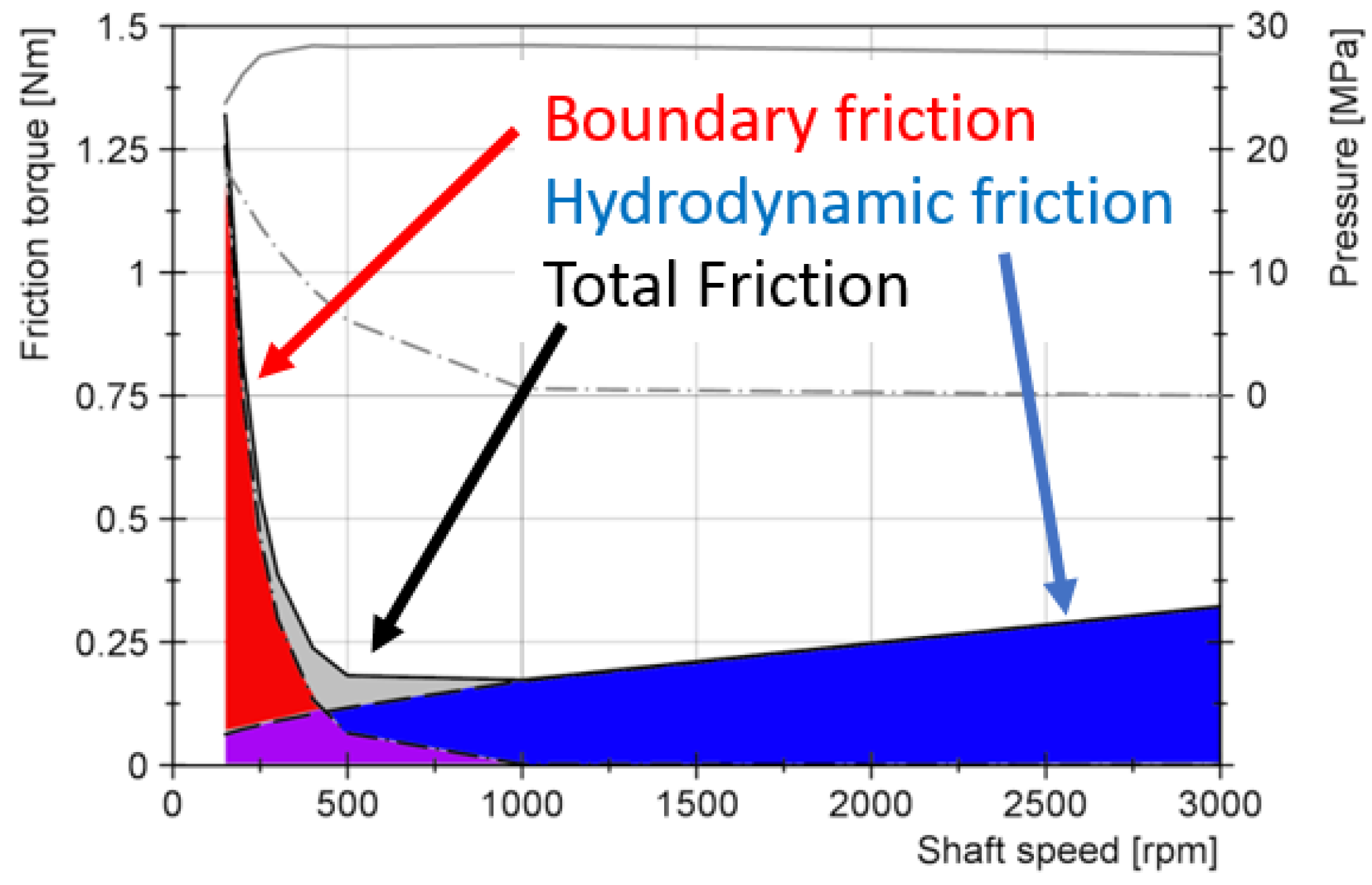
1]. However, there are different regimes of friction that are usually represented by the Stribeck curve: purely hydrodynamic lubrication, boundary friction, and the mixed lubrication regime, where both of these forms of friction coexist. These different schemes are shown for a statically loaded journal bearing in
Figure 1.
Lubricated contacts which are present in internal combustion engines might be assumed to operate in purely hydrodynamic lubrication. With this form of lubrication, a sufficiently thick oil film separates the two gliding surfaces from each other and the friction in this oil film generates the observed losses. Purely hydrodynamic lubrication is advantageous in principle as there is no actual contact between the surfaces and consequently no wear can occur. The reality is more complex as the transient nature of operation for internal combustion engines prevents pure hydrodynamic lubrication (for example, during starting).
Furthermore, the Stribeck curve shows that the minimum of the friction losses is located in the mixed lubrication regime where some surface contact is present. Consequently, the continued efforts to reduce the friction losses in internal combustion engines have led to the regular appearance of mixed lubrication. Excessive wear is typically countered with either oil additive chemistry or surface coatings, and is often combined with a very smooth surface topography.
In the previous two parts of this series, a novel method to investigate friction in internal combustion engines was presented (see part 1 [
3]), and applied to three engines from different engine architectures (see part 2 [
4]). The friction losses were investigated by combining experimental testing with accurate simulation techniques.
However, by merely determining the quantity of present mechanical friction losses [
5], no insight can be gained about the dominant form of friction or how close the engine is to the minimum friction point. Furthermore, potential harmful boundary friction and increased risk of failure for lubricated contacts cannot be located without investigating the engine’s sub-systems. Potential risks that arise from reduced oil viscosity, and consequently by enhanced metal to metal contact are, for example, increased wear, component degradation, surface damage, or bearing seizures. Therefore, the third part of this series aims to extend the basis provided by the previous works, by analyzing the lubrication regime of these three investigated engines.
In contrast to published works that investigate the lubrication regime only in a global context [
6,
7], or for specific parts of an engine [
8,
9], like, for example, the main and big end bearings [
10], the piston assembly [
11,
12,
13,
14,
15], valve train [
16,
17,
18] or even of rotary crank shaft seals [
19], the present work analyzes all individual sub-assemblies (main and big end bearings, piston assembly, and combined valve-train/timing drive) of the same specific engines for the entire range of operating conditions, including engine load.
The approach used to investigate the lubrication conditions for the three engines and their sub-systems is as follows: by varying the media temperature of the engine under test, the lubrication conditions in all contacts are simultaneously affected. A viscosity reduction is achieved by increasing the temperature, thus simulating the use of a low-viscosity engine oil. Consequently, the friction losses of the three engines are determined for different media temperatures: 70
C and 90
C. Conventional motor oils show a strong dependency of dynamic viscosity on temperature [
20]; therefore, a temperature increase of 20
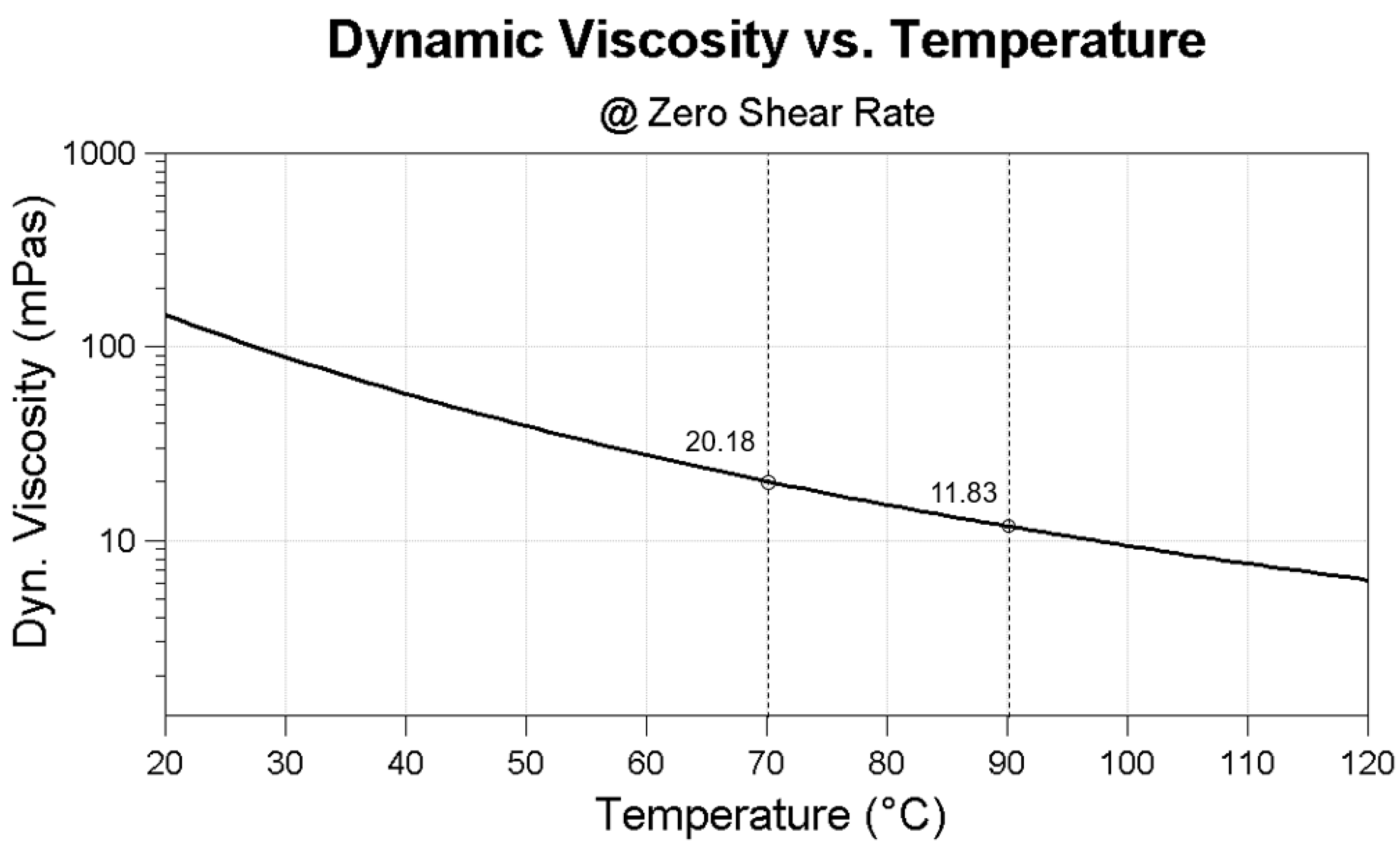
C corresponds roughly to reducing the oil viscosity in half. The following
Figure 2 shows the behavior of the lubricant viscosity for the SAE (Society of Automotive Engineers) 5W30 lubricant used in this work when increasing the lubricant temperature. When increasing the temperature from 70
C to 90
C, the dynamic viscosity decreases from 20.18 mPas to 11.83 mPas, respectively, which represents a viscosity reduction of 41%. For comparison, the use of engine oils with a difference of two SAE classes (for example, SAE 30 and SAE 16) is given here.
The friction loss due to hydrodynamic shear stress in a lubricating film is directly proportional to lubricant viscosity [
2]. Therefore, assuming pure—or at least strongly dominating—hydrodynamic lubrication, reducing viscosity also reduces the friction losses correspondingly. This is the same argument that led to the widespread use of continuously lower viscosity lubricants in engines to achieve lower fuel consumption. However, if the determined friction losses for the increased media temperature do not change or even increase, this indicates the presence of significant amounts of mixed lubrication (see also
Figure 1). This work therefore investigates the friction increase (risk) and friction decrease (reduction potential) using the previously presented combined experimental and numerical approach.
The novelty of this work is that the lubrication analysis is performed not only for the three full base engines, but also to their subsystems. However, the evaluation is not carried out by strip tests to determine the friction losses of the individual components, but by applying the combined methodology developed to the overall system. In addition, the investigations on the individual piston assembly, main and big end bearings, and combined valve train/timing drive systems of the engines are performed on passenger car engines of the same size with the same or twice the specific power. This enables the friction potential and risk assessment analysis in relation to conventional and down-sized concepts.
2. Test Program and Test Procedure
The applied analysis used a specifically coordinated procedure [
3], combining predictive journal bearing simulations and accurate measurements. The investigations are carried out on three different engines for passenger car applications, two gasoline engines, and one diesel engine. The engines have been specifically chosen according to their power density. This allows the analysis of the friction losses not only between diesel and gasoline engine architectures, but also with a focus on the specific power output.
Table 1 lists the main technical data of the engines investigated in this work.
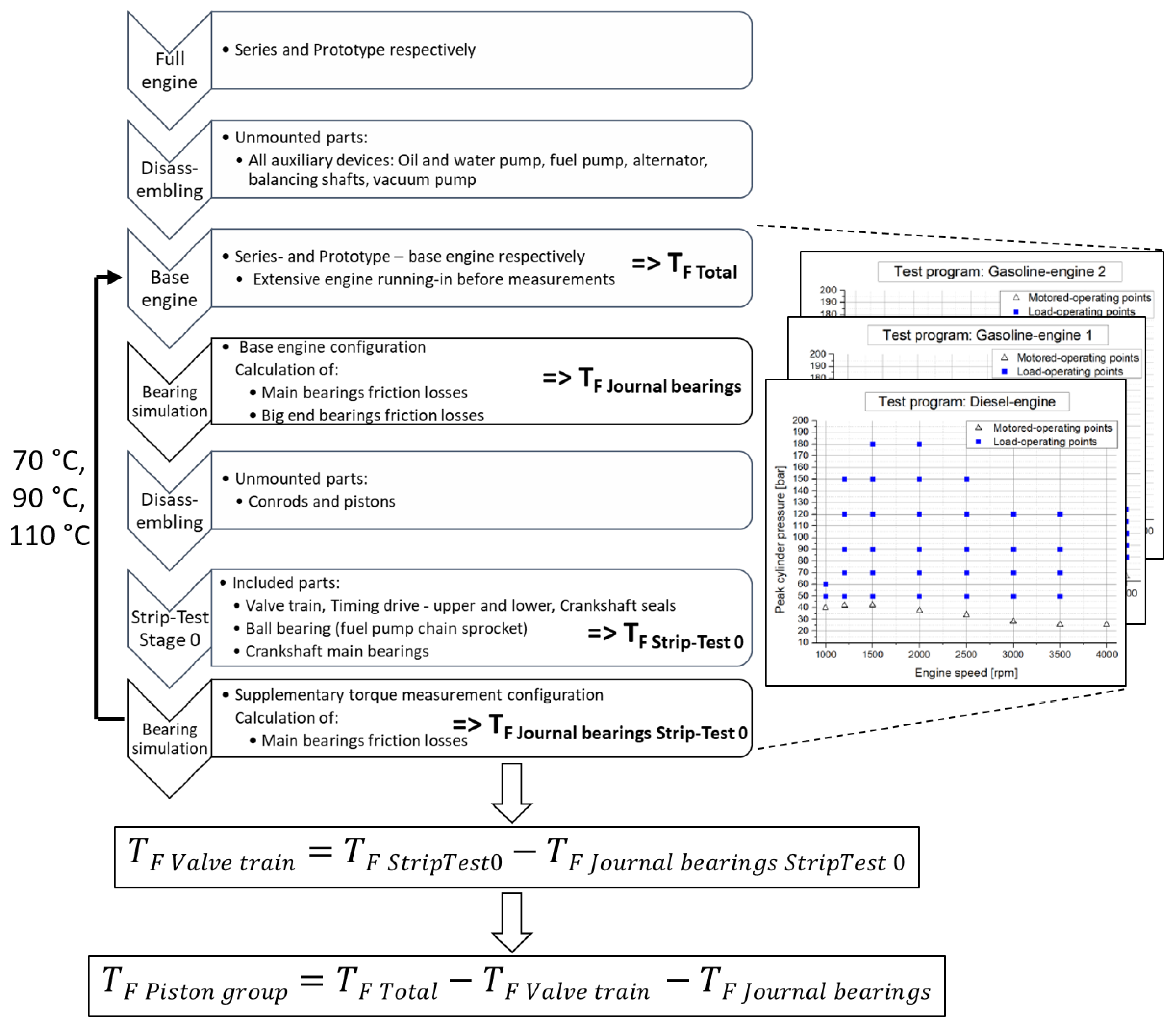
The diesel engine and gasoline engine 1 represent conventional engine concepts with almost the same specific power output. Gasoline engine 2 is designed as a high-power downsized engine concept, and has the doubled power density in comparison to the conventional concepts. The following
Figure 3 shows the overview of the used procedure to conduct the potential analysis on the sub-assembly level of the base engines.
The determination of the total friction losses is done experimentally using the IMEP (indicated mean effective pressure)-method. For the sake of completeness, the main equations when using the IMEP-method are presented here (for example, see textbook [
21]),
where the FMEP is calculated by a subtraction of the IMEP and BMEP (brake mean effective pressure) according to Equation (
1).
For the calculation of the BMEP (Equation (
2)), the measured brake torque at the crankshaft (T) is related to the corresponding mean effective pressure (BMEP)
where
W refers to the work per cycle and
to the volume displacement of the investigated four-stroke engine.
Equation (
3) describes the calculation of the IMEP by integrating the measured cylinder pressure (
) over a working cycle divided by the volume displacement of the engine:
For all three engines investigated in this work, the same analysis procedure (see
Figure 3) is used after disassembling the full engine to the base engine level. By combination and subtraction of the individual friction losses received at the respective engine media supply temperatures (70
C and 90
C), the resulting friction loss reduction and increase are calculated.
The risk assessment in this work is conducted by analyzing the increase in friction when temperature is increased. An increased temperature lowers the viscosity, and it is expected that friction in the mixed and boundary lubrication regime increases due to more severe metal to metal contact. More severe metal to metal contact is potentially harmful to components in the lubricated contacts, and, therefore, it is considered to be a risk when friction increases.
3. Sub-Assembly Resolved Friction Reduction Potentials and Risks
In the following section, the sub-assembly resolved friction reduction potentials and risks are presented for the diesel engine, gasoline engine 1, and gasoline engine 2, when increasing the lubricant and water supply temperature from 70 C to 90 C. For each of the three engines, the results are plotted in one figure including all four sub-assembly systems investigated.
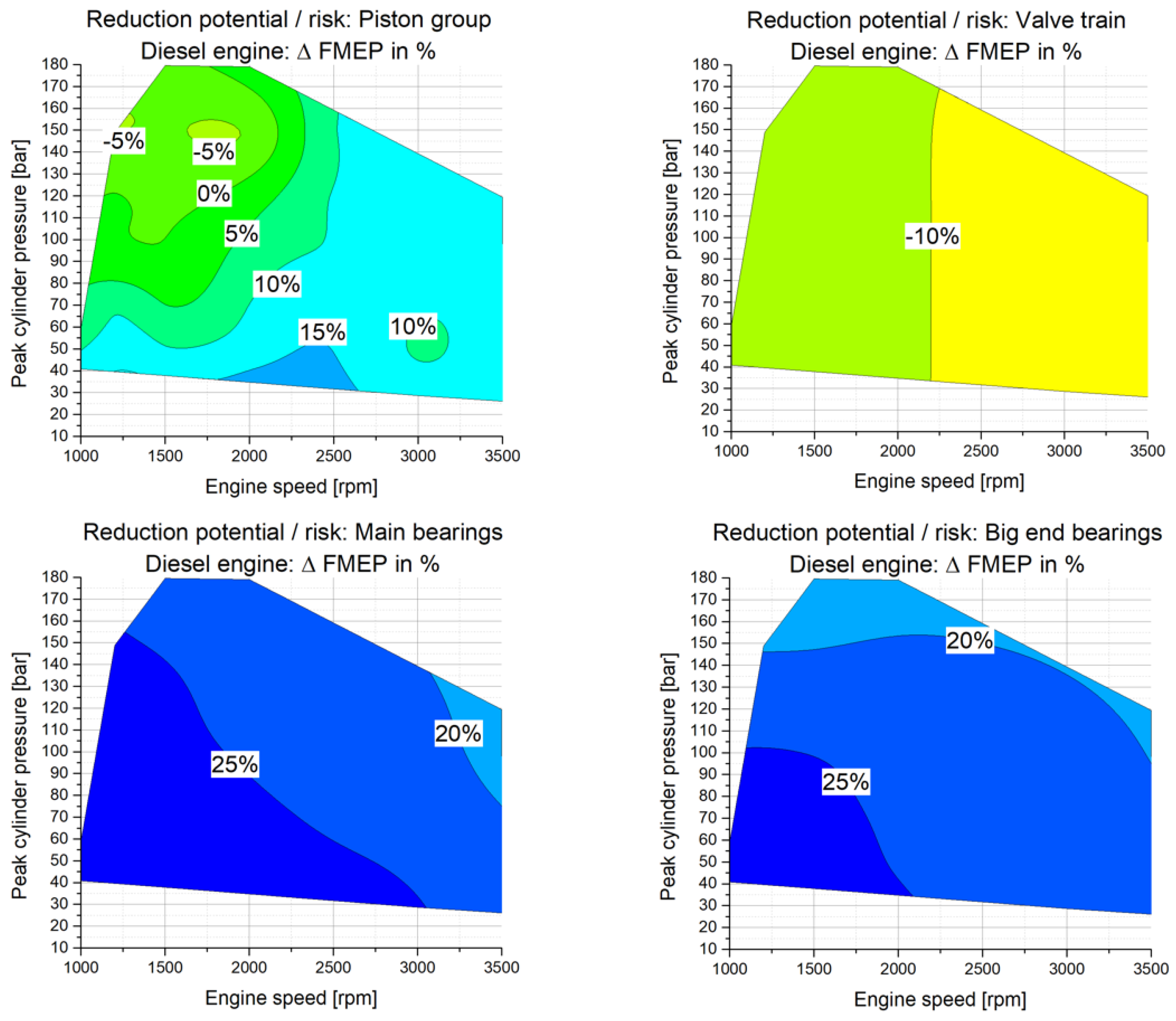
Diesel engine: The results of the potential analysis for the diesel engine when increasing the engine media supply temperature from 70
C to 90
C are presented in
Figure 4. It is interesting to note that the crankshaft journal bearings (main and big end bearings) revealed a significant decrease of the friction losses when increasing the lubricant supply temperature between 16% and 30%, which indicates an operation mainly in the hydrodynamic lubrication regime. For the piston group, the same trend is found for a wide range of engine operation. Especially at low load operation and engine speeds between n = 1500 rpm and n = 2500 rpm, the FMEP decreases by 16%. For engine speeds lower than n = 2000 rpm and high engine loads, the FMEP values partially increase up to 7% indicating mixed lubrication. On the other hand, the valve train friction losses share (including crankshaft seals and timing drive) increase with increasing engine media supply temperature in the range of 9% to 11%. It was found in part 1 of this publication series [
3] that the disadvantages at the combined valve train/timing drive system arise largely from the timing drive part.
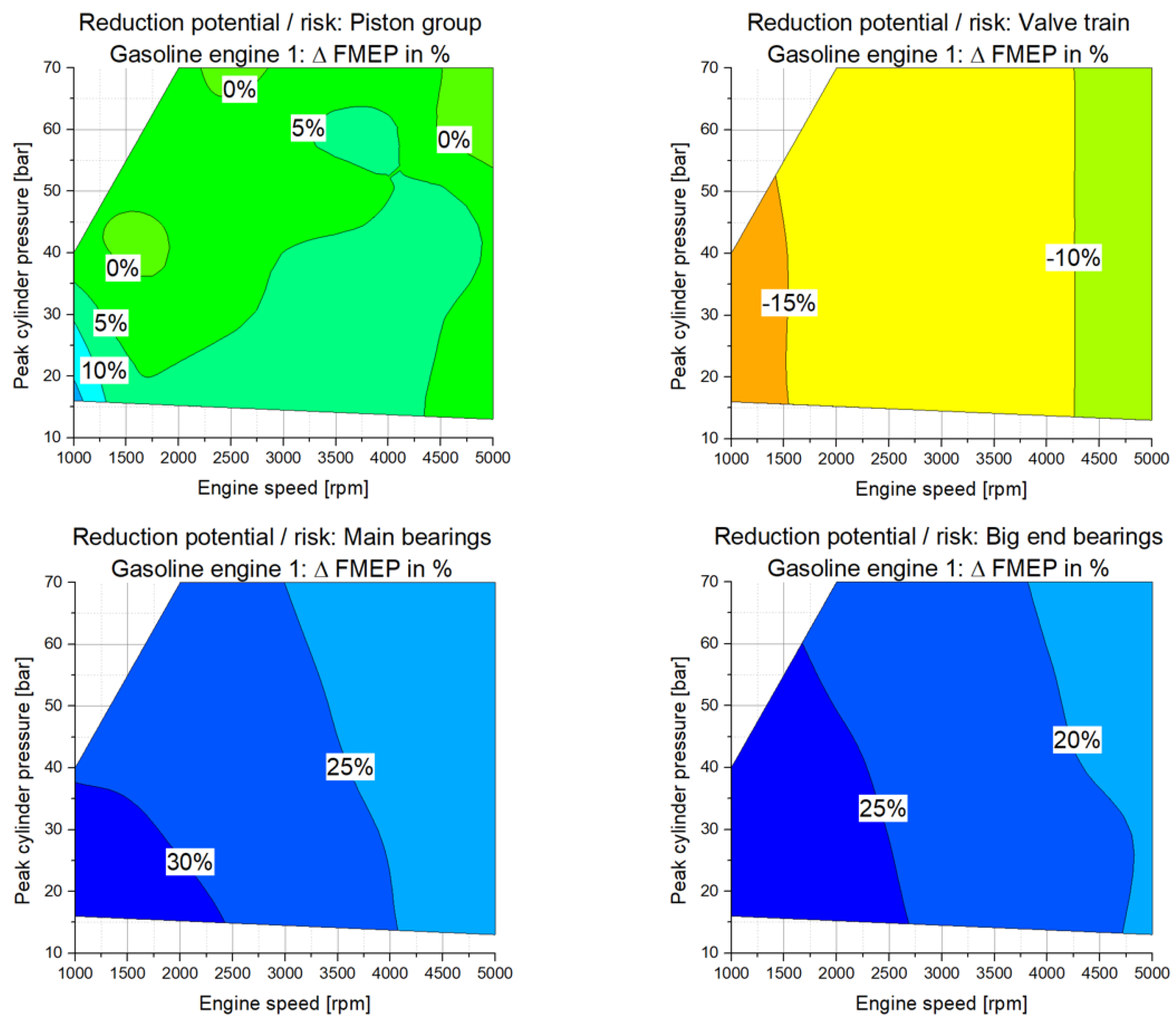
Gasoline engine 1: The results of the friction reduction potential analysis for the gasoline engine 1 when increasing the engine media supply temperature from 70
C to 90
C are presented in
Figure 5.
For the crankshaft main bearings and big end bearings, it was found that a temperature increase of the engine media (cooling water and lubricant) results in marginal friction reduction in the range of 18% to 32%. The results for the crankshaft journal bearings indicate an operation in the hydrodynamic lubrication regime. For the piston group assembly, advantages of up to 19% are investigated at very low loads and engine speeds below n = 1500 rpm. Beyond low speeds and low loads, the friction loss potential analysis at the piston group shows both disadvantages up to −5% indicating mixed lubrication regimes, as well as reduction potentials up to 10%. It is further interesting to note that, for the valve train system which is designed as flat-tappet based valve actuation system, the friction losses are strongly affected by the lubricant supply temperature. Similar results for the flat-tappet based based systems are found in [
22]. The friction losses increase between 9% at high engine speeds and 18% at low engine speeds. Especially at low engine speeds, the friction losses increase to a greater extent, where subsequently reduced rotational speeds are present at the interaction between flat tappet and cam.
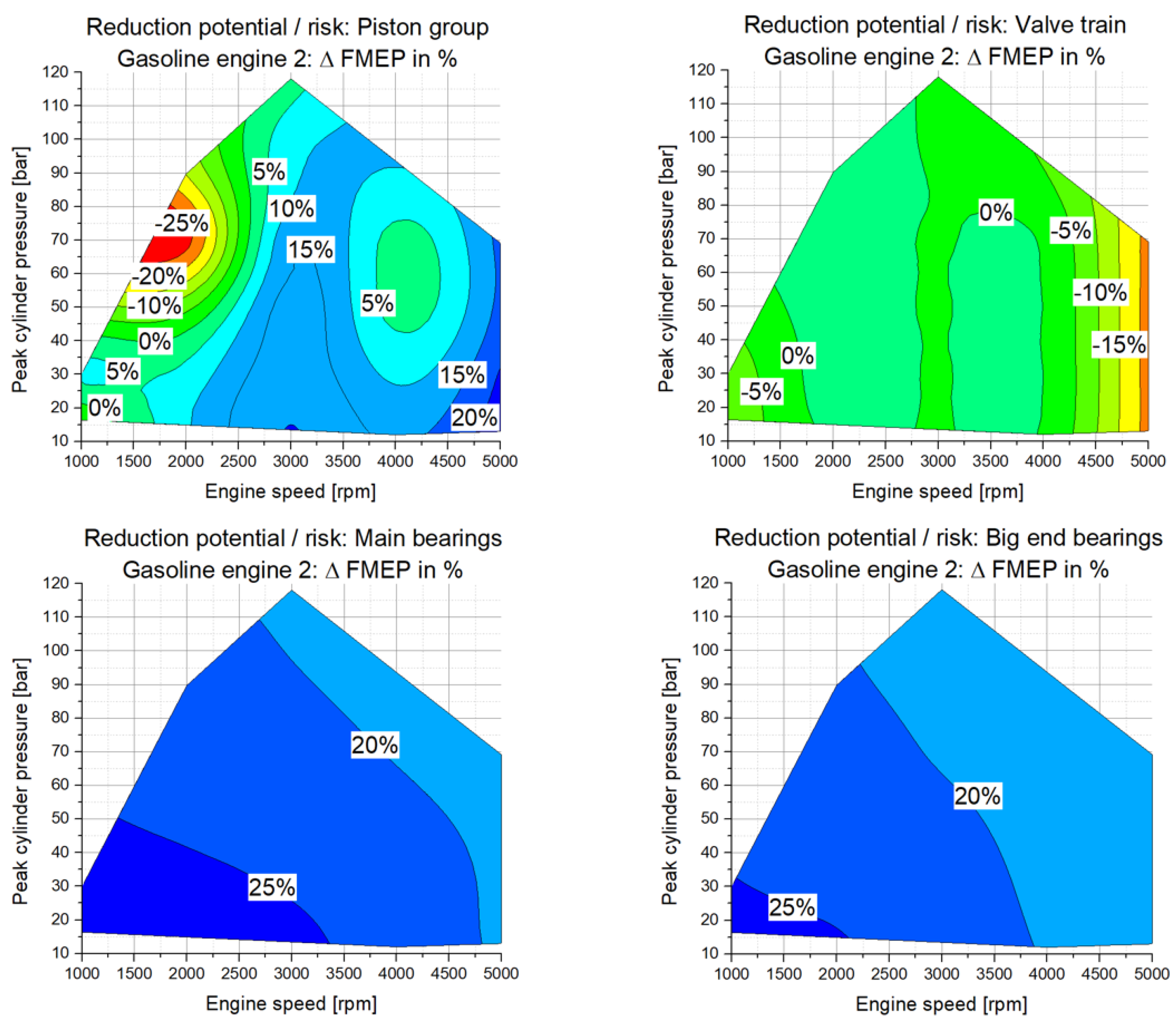
Gasoline engine 2: For gasoline engine 2, the friction potential investigation has been carried out for identical thermal boundary conditions compared to the other engines. The engine media supply temperature has been varied from 70
C to 90
C and the following
Figure 6 shows the results of the friction potential analysis.
For the crankshaft journal bearings, a friction reduction in the range of 16% to 29% results from the conducted potential analysis. This indicates an operation of the journal bearings in the hydrodynamic lubrication regime. For the piston group, varying results are obtained, while, at engine speeds above n = 2500 rpm, friction reduction potentials of up to 23% are investigated, the behavior at low engine speeds is different. Especially at engine speeds below n = 2000 rpm and high load conditions, marginal disadvantages of up to −29% arise indicating significant mixed lubrication regimes in the piston group sub-assembly. The results for the piston group clearly show the high requirements for high power downsized engine architectures. Particularly at low loads and low engine speeds, the limit between operation in hydrodynamic and mixed lubrication regime is reached, and limits possible friction reduction when the viscosity of the lubricant is reduced. For the valve train friction losses (incl. timing drive and crankshaft seals friction losses), it is interesting to note that, for engine speeds below n = 2000 rpm, the friction losses increase up to 9% when increasing the engine media supply temperature. Additionally, for high engine speeds above n = 4000 rpm, the friction losses significantly increase up to 22%. For engine speeds in the range between n = 2000 rpm and n = 4000 rpm, the friction reduction potential is to a minor extent. The reduction potential/risk is small ranging between an advantage of 3% and a disadvantage of −1%.
4. Base Engine Friction Losses and Resulting Global Potentials and Risks
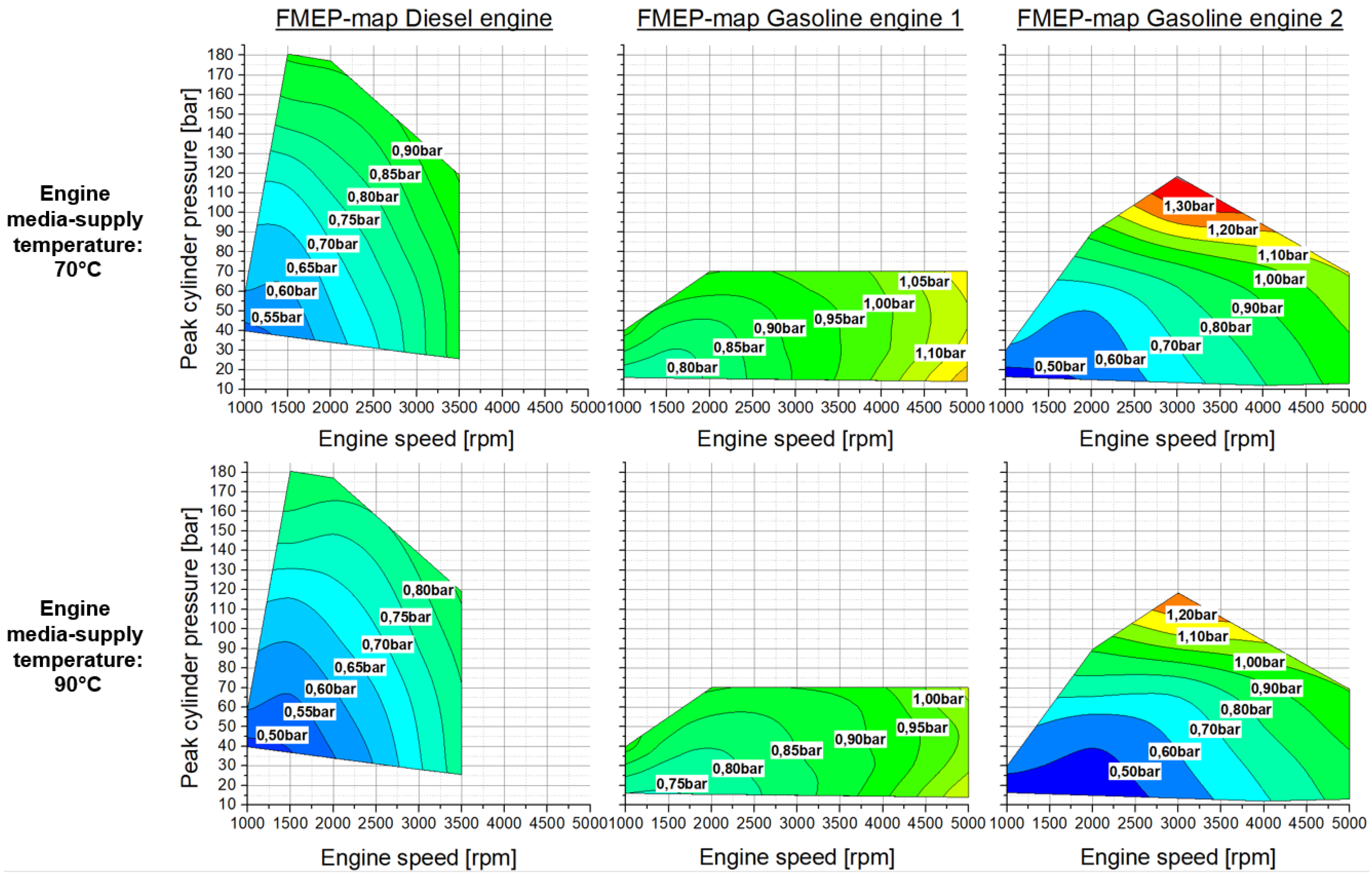
The total friction losses (T
F Total) of the three engine concepts have been investigated according to the analysis procedure presented in
Figure 3. Since the base engine friction results are obtained at engine media supply temperatures of 70
C and 90
C, the friction reduction potential analysis can be performed not only at the sub-assembly level of the engines, but also at the global base engine level. This is done by subtraction of the FMEP results at the individual temperature level, and enables comparison of the global potential and risks at the base engine level. Subsequently, possible advantages using the presented combined approach are explained in detail. The resulting FMEP-maps at the base engine level of the investigated engine architectures are presented in
Figure 7 (see also [
4]).
By increasing the lubricant supply temperature, a significant decrease of the lubricant viscosity is obtained (see
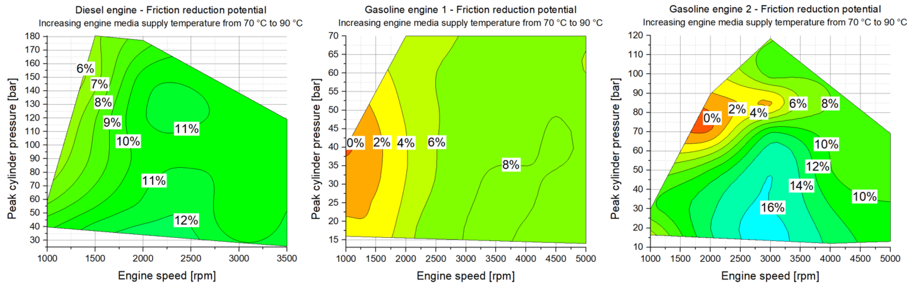
Figure 2), and friction reduction potentials, as well as possible risks due to beginning mixed lubrication regimes are studied. The following
Figure 8 shows the calculated friction reduction/risk potential when increasing the engine media supply temperature of the base engines from 70
C to 90
C.
Diesel engine:
The increase in engine media supply temperature shows friction reduction potentials over the entire engine speed and load range, and advantages up to 13% are investigated. The most significant advantages result at engine speeds higher than n = 1500 rpm. At lower engine speeds between n = 1000 rpm and 1500 rpm, the friction reduction potential is in the range of 6% (at high load operation) to 11% (at low load operation).
Gasoline engine 1:
When the engine media supply temperature is increased from 70
C to 90
C for gasoline engine 1, areas of friction reduction potential near 0% and below signal arising risks (see
Figure 8 middle). At low engine speeds and high loads, disadvantages (risks) of up to −2% arise, indicating mixed lubrication regimes. Furthermore, the overall friction reduction potential ranges between −2% and 9%. This shows that the overall friction reduction potential for this engine is smaller in comparison to the other engines. It is interesting to note that friction reduction potentials above 6% are investigated for engine speeds higher than n = 2000 rpm and low load conditions.
Gasoline engine 2:
Increasing the engine media supply temperature from 70
C to 90
C at gasoline engine 2 results in areas of friction reduction potential near 0% and below (see
Figure 8 right). It is interesting to note that, for engine operation at low loads, significant reduction potential results. For engine speeds above n = 1500 rpm and peak cylinder pressures below pcyl = 50 bar, reduction potentials between 10% and 17% are investigated. When the engine load is increased especially at engine speeds below n = 3000 rpm, the reduction potential decreases and enters levels between −1% and 6%. The results indicate mixed lubrication at engine speeds below n = 2000 rpm and peak cylinder pressures above pcyl = 70 bar.
5. Discussion
The results of the friction potential analysis and risk assessment at the base engine level represents a good example of the advantages when using the combined approach for friction analysis presented in the publicatiosn series [
3,
4]. At the base engine level, for example of gasoline engine 2, the arising risks are rather small between 0% and −2% at low engine speeds and high loads. However, when analyzing the friction reduction at the sub-assembly level (see
Figure 6), arising risks are identified at the piston group system and valve train system. Therefore, the presented analysis procedure enables to place specific focus on measures for developing future engine generations at the relevant sub-assembly systems.
The main and big end bearings at all three engines show large reduction potentials between 16% and 30% and indicate an operation mainly in the hydrodynamic lubrication regime. For the piston group system of the diesel engine and gasoline engine 1, friction reduction potentials up to 16% are found. It is interesting to note that the reduction potential at the piston group system are identified at different areas of engine operation, while, for gasoline engine 1, reduction potentials are found at low speed and low load operation, reduction potentials for the diesel engine are found at medium speed and low load operation. Both engines reveal beginning mixed lubrication to a minor extent when increasing the engine media supply temperature from 70 C to 90 C for low engine speeds and high load operation. Here, the friction levels increase up to 7%.
The most significant results are obtained for the piston group of gasoline engine 2, which is designed as a high-power downsizing concept. For low load operation friction, reduction potentials up to 23% are obtained, and the results at low engine speed and high load operation are significantly different. It is found that arising risks are present at engine speeds below n = 2000 rpm and peak cylinder pressures above pcyl = 50 bar. At these operation points, disadvantages of up to 29% are identified.
The analysis of the valve train system for the diesel and gasoline engine 1 reveal that friction losses increase between 9% and 11% for the diesel engine, and between 9% and 18% for gasoline engine 1 when the engine media supply temperature is increased from 70 C and 90 C. For the valve train system of gasoline engine 2, a slight friction reduction potential of up to 3% is investigated at engine speeds between n = 2000 rpm and n = 4000 rpm. However, at engine speeds below n = 2000 rpm and above n = 4000 rpm, the friction losses increase when the supply temperature is increased from 70 C to 90 C, while, at the low engine speeds, the increase is up to 9%, and the increase at high engine speeds is significant with 22%.
6. Conclusions
The sub-assembly resolved friction reduction potentials and risks when reducing the lubricant viscosity are investigated for three different engine concepts for passenger car applications. By using a developed combined approach, the friction losses of one diesel engine, a gasoline engine with the same specific power, and a gasoline engine with doubled power density are analyzed. The base engine friction losses are separated into the sub-assemblies piston group, crankshaft journal bearings, and valve train over the full operation range of the engines.
One suitable 5W30 lubricant is chosen for all three engines to exclude influences from different lubricants. By supplying the engine media (lubricant and cooling water) by external supply units, identical thermal boundary conditions are realized for the investigations. The viscosity reduction is achieved by increasing the supply temperature from 70 C to 90 C.
The results of the conducted friction reduction potential analysis show significant differences at the sub-assembly systems. The main bearings and big-end bearings show a high potential to reduce friction by increasing the lubricant temperature. A contrary behavior shows the valve train where a temperature increase results in an increase in friction losses. Dependent on the valve train design, the friction increase is more or less significant. The piston assembly shows varying friction reduction potential over the investigated speed and load range. Generally, the friction losses are reduced at high speed and at low loads. At high load and low speed conditions, the friction benefit vanishes or turns into a friction increase in particular for the investigated gasoline engine 2.
Furthermore, it is shown that a potential harmful increase of friction loss of a single sub-system cannot be identified when the entire base engine is evaluated. For instance, friction reduction in the bearings may cancel the increase of friction in the valve train or the piston assembly. Therefore, a friction analysis of the engine’s sub-systems is essential.
Author Contributions
Conceptualization, C.K., H.A., and D.E.S.; Data curation, C.K., H.A., and D.E.S.; Funding acquisition, H.A.; Investigation, C.K., H.A., and D.E.S.; Methodology, C.K., H.A., and D.E.S.; Supervision, H.A. and T.S.; Validation, C.K., H.A., D.E.S., and T.S.; Writing—original draft, C.K. All authors have read and agreed to the published version of the manuscript.
Acknowledgments
The authors gratefully acknowledge funding of the Austrian Science Fund (FWF) for the project P27806-N30. The publication was written at Virtual Vehicle Research GmbH in Graz and partially funded by the COMET K2—Competence Centers for Excellent Technologies Programme of the Federal Ministry for Climate Action (bmk), the Federal Ministry for Digital and Economic Affairs (bmdw), the Austrian Research Promotion Agency (FFG), and the Province of Styria and the Styrian Business Promotion Agency (SFG).
Conflicts of Interest
The authors declare no conflict of interest.
References
- Sander, D.E.; Knauder, C.; Allmaier, H. Potentiale und Risiken von (Ultra-)Leichtlaufölen zur Senkung der Motorreibung. In Reibung in Antrieb und Fahrzeug; Springer Vieweg: Wiesbaden, Germany, 2018; pp. 179–190. [Google Scholar]
- Sander, D.E.; Allmaier, H.; Priebsch, H.H.; Witt, M.; Skiadas, A. Simulation of journal bearing friction in severe mixed lubrication—Validation and effect of surface smoothing due to running-in. Tribol. Int. 2016, 96, 173–183. [Google Scholar] [CrossRef] [Green Version]
- Knauder, C.; Allmaier, H.; Sander, D.E.; Sams, T. Investigations of the friction losses of different engine concepts. Part 1: A combined approach for applying sub-assembly resolved friction loss analysis on a modern passenger car diesel engine. Lubricants 2019, 7, 39. [Google Scholar] [CrossRef] [Green Version]
- Knauder, C.; Allmaier, H.; Sander, D.E.; Sams, T. Investigations of the friction losses of different engine concepts. Part 2: Sub-assembly resolved friction loss comparison of three engines. Lubricants 2019, 7, 109. [Google Scholar] [CrossRef] [Green Version]
- Kovach, J.T.; Tsakiris, E.A.; Wong, L.T. Engine friction reduction for improved fuel economy. SAE Tech. Pap. 1982. [Google Scholar] [CrossRef]
- Wong, V.W.; Tung, S.C. Overview of automotive engine friction and reduction trends—Effects of surface, material, and lubricant-additive technologies. Friction 2016, 4, 1–28. [Google Scholar] [CrossRef] [Green Version]
- Coy, R.C. Practical applications of lubrication models in engines. Tribol. Int. 1998, 31, 563–571. [Google Scholar] [CrossRef]
- Priest, M.; Taylor, C.M. Automobile engine tribology—Approaching the surface. Wear 2000, 241, 193–203. [Google Scholar] [CrossRef]
- Offner, G. Friction power loss simulation of internal combustion engines considering mixed lubricated radial slider, axial slider and piston to liner contacts. Trib. Trans. 2013, 56, 503–515. [Google Scholar] [CrossRef]
- Knauder, C.; Allmaier, H.; Sander, D.E.; Salhofer, S.; Reich, F.; Sams, T. Analysis of the journal bearing friction losses in a heavy-duty diesel engine. Lubricants 2015, 3, 142–154. [Google Scholar] [CrossRef]
- Kim, K.; Shah, P.; Takiguchi, M.; Aoki, S. Part 3: A study of friction and lubrication behavior for gasoline piston skirt profile concepts. SAE Tech. Pap. 2009. [Google Scholar] [CrossRef] [Green Version]
- Westerfield, Z.; Totaro, P.; Kim, D.; Tian, T. An experimental study of piston skirt roughness and profiles on piston friction using the floating liner engine. SAE Tech. Pap. 2016. [Google Scholar] [CrossRef]
- Ma, M.T.; Sherrington, I.; Smith, E.H. Analysis of lubrication and friction for a complete piston-ring pack with an improved oil availability model: Part 1: Circumferentially uniform film. Proc. Inst. Mech. Eng. J. 1997, 211, 1–15. [Google Scholar] [CrossRef]
- Ma, M.T.; Smith, E.H.; Sherrington, I. Analysis of lubrication and friction for a complete piston-ring pack with an improved oil availability model: Part 2: Circumferentially variable film. Proc. Inst. Mech. Eng. J. 1997, 211, 17–27. [Google Scholar] [CrossRef]
- Taylor, R.I.; Brown, M.A.; Thompson, D.M.; Bell, J.C. The influence of lubricant rheology on friction in the piston ring-pack. SAE Trans. 1994, 103, 1390–1399. [Google Scholar]
- Taylor, C.M. Valve train-cam and follower: Background and lubrication analysis. Tribol. Ser. 1993, 26, 159–181. [Google Scholar]
- Mufti, R.A.; Priest, M. Experimental and theoretical study of instantaneous engine valve train friction. J. Trib. 2003, 125, 628–637. [Google Scholar] [CrossRef]
- Staron, J.T.; Willermet, P.A. An analysis of valve train friction in terms of lubrication principles. SAE Trans. 1983, 92, 625–639. [Google Scholar]
- Knauder, C.; Allmaier, H.; Sander, D.E.; Sams, T. Measurement of the crankshaft seals friction losses in a modern passenger car diesel engine. Proc. Inst. Mech. Eng. J. 2019. [Google Scholar] [CrossRef] [Green Version]
- Allmaier, H.; Priestner, C.; Sander, D.E.; Reich, F.M. Friction in automotive engines. In Tribology in Engineering; Pihtili, H., Ed.; Intech: Rijeka, Croatia, 2013; pp. 149–184. [Google Scholar]
- Heywood, J.B. Engine friction and lubrication. In Internal Combustion Engine Fundamentals; Holman, J.P., Ed.; McGraw-Hill, Inc.: New York, NY, USA, 1988; pp. 712–747. [Google Scholar]
- Taylor, R.I.; Morgan, N.; Mainwaring, R.; Davenport, T. How much mixed/boundary friction is there in an engine—In addition, where is it? Proc. Inst. Mech. Eng. J. 2019. [Google Scholar] [CrossRef]
© 2020 by the authors. Licensee MDPI, Basel, Switzerland. This article is an open access article distributed under the terms and conditions of the Creative Commons Attribution (CC BY) license (http://creativecommons.org/licenses/by/4.0/).


