Wear of AlCrN and CrAlSiN Coatings Applied to Nonstandard Involute Gears


1
Institute of Technologies and Materials, Faculty of Mechanical Engineering, Slovak University of Technology in Bratislava, Námestie Slobody 17, 812 31 Bratislava, Slovakia
2
Institute of Transport Technology and Designing, Faculty of Mechanical Engineering, Slovak University of Technology in Bratislava, Námestie Slobody 17, 812 31 Bratislava, Slovakia
3
Department of Machine Design, Faculty of Engineering, Slovak University of Agriculture in Nitra, Tr. A. Hlinku 2, 949 76 Nitra, Slovakia
*
Author to whom correspondence should be addressed.
Lubricants 2021, 9(5), 54; https://0-doi-org.brum.beds.ac.uk/10.3390/lubricants9050054
Submission received: 9 March 2021
/
Revised: 29 April 2021
/
Accepted: 7 May 2021
/
Published: 8 May 2021
Abstract
:Wear of nonstandard involute gears with two types of coatings, AlCrN and CrAlSiN, was studied. The coatings were applied by cathodic arc deposition. The gears were tested using a Niemann tester at a graduated load up to the 12th load stage and were compared to noncoated gears. Both Biogear S150 gear oil and PP90 universal hydraulic oil were applied during these tests. The thickness of deposited coatings and wear of gear teeth were studied by SEM and their chemical compositions were determined by EDS analysis. Maximal contact pressure of 1350 MPa was calculated in the region of the tooth flank at the 12th load stage. Maximal frictional stress was also calculated on the tooth flank. The resistance against wear of gears was evaluated based on the critical weight loss and mainly based on the critical surface roughness of gears. The critical roughness was exceeded at the 10th load stage for noncoated gears. For the gears with AlCrN and CrAlSiN coatings, the critical roughness was exceeded at the 11th load stage. Wear of AlCrN and CrAlSiN coatings was nonuniform along the height of tooth. Wear on the tooth flank was characterized by fragmentation of thin coatings and subsequent detaching of fragments from the steel substrate. The steel substrate was worn by microcutting, which caused the highest roughness on the tooth surface. On the tooth pitch, surface protrusions of coatings were smoothed, and coatings cracked and locally detached subsequently. On the tooth face, surface protrusions were also smoothed but coatings remained compact without crack initiations. Both experimental oils, Biogear S150 and PP90, proved to be suitable during Niemann tests as their temperatures did not exceed the limit value of 80 °C.
1. Introduction
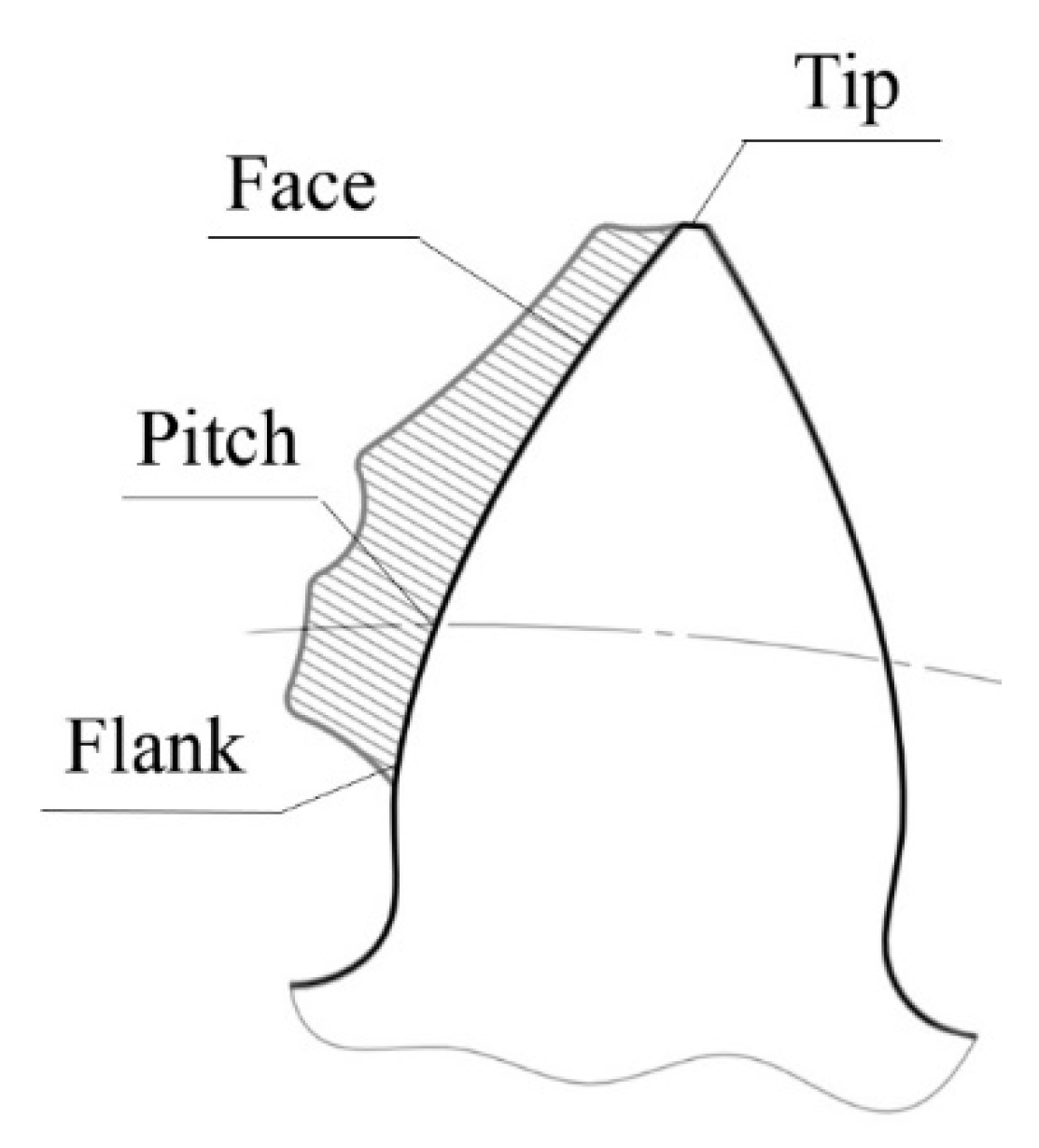
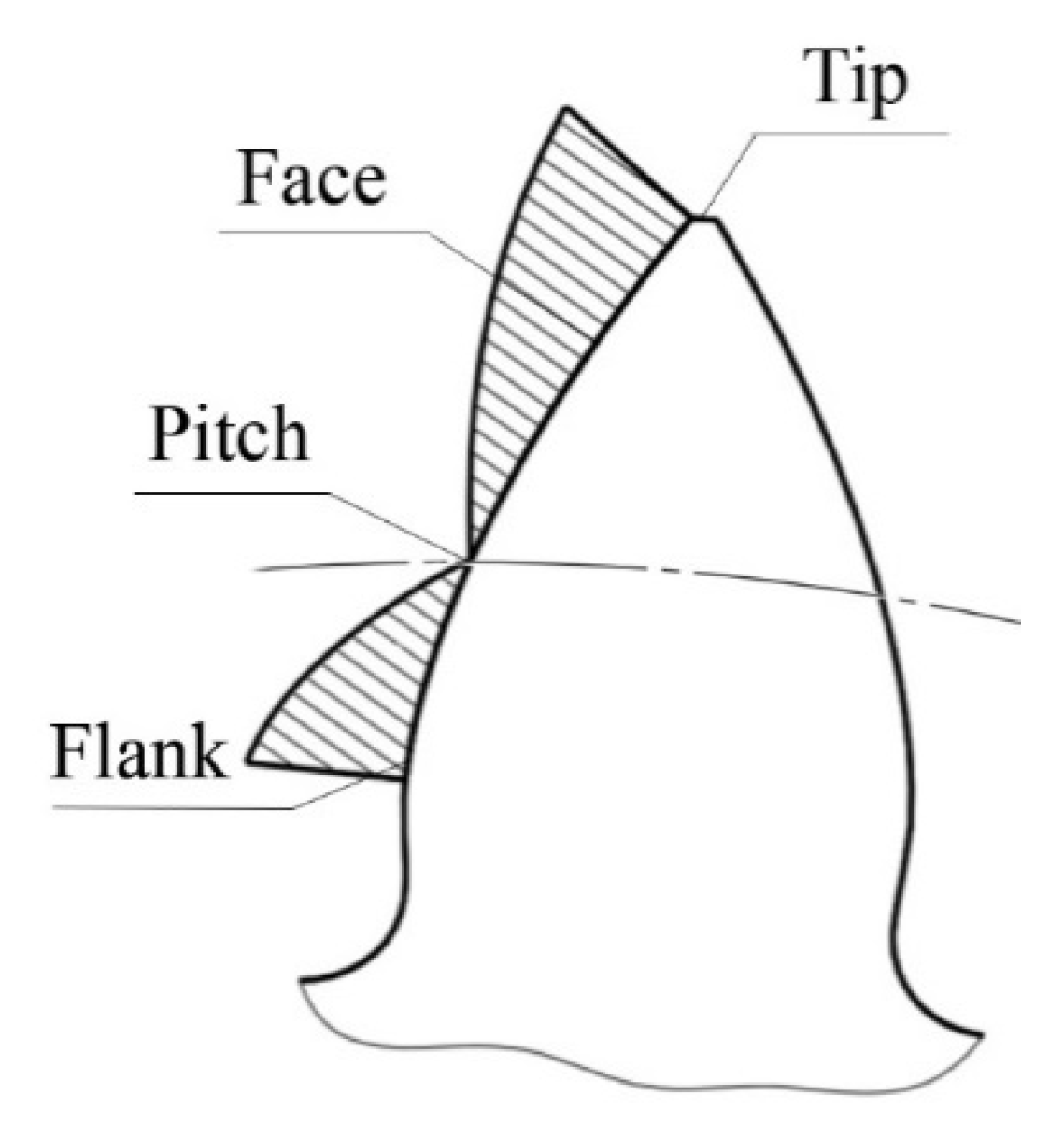
The involute gear is one of the most widespread and most widely used gears in industrial production. We distinguish between standard involute gearing (LCR—Low Contact Ratio) and a nonstandard involute gearing with long teeth (HCR—High Contact Ratio). LCR and HCR differ in geometric parameters of the basic profile. In general, for a correct mesh of a spur gear with straight teeth, it must be true that there is still more than one pair of teeth in mesh. In standard LCR gearing, the teeth come into contact in single-pair or double-pair mesh. The distribution of the normal force for LCR gearing is shown in Figure 1 and for HCR in Figure 2 [1]. From the comparison of these figures, different normal forces in pitch regions of the teeth can be seen. In standard LCR gearing, the normal force in this region is maximal, but in HCR gearing it is minimal. This is caused by larger number of teeth in the mesh in HCR gearing compared to LCR gearing. Thus, in HCR gearing, the load is distributed to a larger number of teeth than in LCR gearing. A larger number of teeth in the mesh results in reduction in the load of the teeth in the contact and in the bending. HCR gears are also quieter in operation than LCR gears [2]. For these reasons, HCR gears have begun to be used more in gear boxes in the automotive industry [3], despite having a higher slip ratio compared to LCR gears. In the case of coated HCR gears, this higher slip ratio increases the risk of the coating separation from the substrate [4].
Contact pressure is the most important parameter and influences the load capacity and wear resistance of contacting surfaces in gear and bearing mechanisms. The contact pressure is influenced by several factors such as lubricant and manufacturing errors, but the most important factor is the surface roughness. The roughness of the surface greatly affects the contact pressure in bearing systems [5]. However, in gear mechanisms, the effect of the surface roughness is less important and can be neglected during simulation as the measured contact pressures in the gear mechanisms does not differ significantly from the calculated ones [6,7,8].
Technological approach to the increase in load capacity of gears involves various sophisticated technologies, including chemical and thermal treatment methods [9]. The wear resistance of steel parts is usually increased by application of surface coatings [10], which are resistant to enhanced temperatures [11], corrosion [12] and complex load conditions [13]. The progress in surface engineering has enabled applications of several deposition methods such as PVD, CVD, and PACVD, with the aim of increasing surface bearing capacity of gear teeth [14,15]. Deposition of hard thin coatings on the gear tooth surface is one way of increasing the surface bearing capacity of the teeth, which enables one to increase the load capacity of gears while maintaining their required lifetime [16,17].
The choice of a suitable coating for application in gears represents a demanding process due to the specific conditions at tooth contact during meshing. This process is impacted by several factors. The coatings should be resistant to high pressures during gear meshing and to high temperatures, up to 450 °C. They should be inert to mineral, synthetic or ecologic lubricants. They must have sufficient adhesion on gear tooth surface and small friction coefficients. These properties are fulfilled by chromium nitride with aluminum (AlCrN), which is characterized by high wear resistance [18] and oxidation resistance [19]. The AlCrN coatings have good adhesion to steel substrate [20]. Significant increase in lifetime of gears can be expected by application of coatings consisting of chromium nitride with aluminum and silicon (CrAlSiN) [21,22]. CrAlSiN has higher hardness and wear resistance at room temperature [23,24], as well as at enhanced temperatures [25], compared to AlCrN coatings.
AlCrN and CrAlSiN coatings could be deponed by CVD methods, which requires high deposition temperatures from 900 to 1000 °C [26,27,28]. The application of high temperatures decreases hardness of a substrate significantly. The accuracy class of gears decreases by two degrees due to deformation. Thin AlCrN and CrAlSiN coatings could be deponed using PACVD methods, which require lower deposition temperatures compared to CVD methods (620–650 °C) [29,30,31]. However, this lower temperature decreases hardness of substrate from hardened steel. The accuracy class of gears decreases by one degree.
The AlCrN and CrAlSiN coatings could be deponed using PVD methods in the temperature interval from 400 to 450 °C. For deposition of these coatings, the radiofrequency sputtering method [31,32] is rarely used—magnetron sputtering [33,34,35,36] is more frequently used. The cathodic arc deposition is the most significant method of PVD deposition for AlCrN and CrAlSiN coatings [37,38,39,40,41,42,43,44].
Before the coating’s deposition, close attention should be paid to the preparation of substrate surfaces. Substrate surface preparation is described in [45,46]. The effect of contamination of substrate surface on quality of substrate–coating interface is detailed and analyzed in [47].
In our work, we focused on wear analysis of coated HCR gears, which are characterized by a high slip ratio. Wear of these gears has not been studied yet. The wear was evaluated on two types of coatings, AlCrN and CrAlSiN, which were applied to the involute HCR gears made of ASTM A576-B1 (C55) steel substrate.
2. Materials and Methods
Experimental gears were made of ASTM A576-B1 (C55) steel which contains 0.57–0.65% C, 0.5–0.8% Mn, 0.15–0.4% Si, max. 0.04% P, and max. 0.4% S. This type of steel is suitable for surface hardening. It is used to produce less loaded gears, pins, spindles, and machine parts, requiring enhanced abrasion resistance. For the deposition of coatings, a roughness Ra below 0.8 µm is required on the gear tooth surface (as demanded by the supplier). To achieve the required roughness, the gears were preceded by a running-in procedure in as-rolled condition. Subsequently, the gears were heated to 800 °C and quenched in oil then tempered at 450 °C and cooled in air. The high tempering temperature (450 °C) hinders the subsequent tempering during relatively long dwelling at the deposition temperature during deposition of the coatings.
The tooth surfaces were cleaned before the coating’s deposition. Gears were removed by alkaline substance in water solution using ultrasonic cleaner. Consequently, the surfaces were washed up with demineralized water, blown using a hot air blow gun and dried in a vacuum chamber. The materials of coatings were chromium nitride with aluminum (AlCrN) and chromium nitride with aluminum and silicon (CrAlSiN). Both coatings were applied by cathodic arc deposition using PLATIT, Pi411 equipment (PLATIT AG, Selzach, Switzerland) in a nitrogen atmosphere. The AlCrN coating was created by deposition of Cr and Al targets at bias voltage of 50 V, nitrogen pressure of 4 Pa, and substrate temperature of 450 °C for 8 h. The CrAlSiN coating was created by deposition of 65Al-35Cr and 82Al-18Si targets at bias voltage of 70 V, nitrogen pressure of 4 Pa, and substrate temperature of 450 °C for 6 h. The same heat treatment was applied for gear without coating.
The same coatings were deposited on disk samples, which were used for measurement of hardness, wear, and friction coefficient of coatings. These samples had a disk with a diameter of 100 mm. Nanohardness was measured using a Berkovitch nanoindenter with force of 5 mN. Wear resistance and friction coefficient of AlCrN and CrAlSiN coatings were measured by the ball on disc method using a tribometer, CSM Instruments (Nanovea Inc., Irvine, CA, USA). The wear tests were performed in dry conditions with Al2O3 balls at a load of 1 N, sample rate of 80 mm.s−1, and on a trajectory with the final length of 100 m. The wear resistance of samples was determined based on the volume loss of the samples, which was measured by the material weight loss of samples and calculated using density of coatings. The friction coefficient was calculated from the frictional and normal force fraction.
The load-bearing capacity of experimental coatings was determined by a Niemann tester with enclosed power flow [48]. This method is equivalent of the ASTM D5182–19 standard [49]. The testing device was made in the workspace of authors at the Institute of Transportation Technology and Design. Coated and noncoated HCR gears were tested at the gradual load stage, which was characterized by gradually increasing torque. The torque value was 2.5 Nm at the 1st load stage, 366.1 Nm at the 10th load stage, 445.4 Nm at the 11th load stage, and 518.5 Nm at the 12th load stage, which was the maximal load applied during the Niemann tests. The resistance of gears in the 12th load stage guarantees unlimited lifetime of tested gears in gear systems.
Experimental gears were tested in interaction with OMV Biogear S150 lubricant (OMV, Vienna, Austria) with an equivalent SAE90 number. The lubricant is environmentally friendly, and apart from gears it is suitable for bearings in agriculture machines [50]. The second tested lubricant was PP90 hydraulic oil (SLOVNAFT, a.s., Bratislava, Slovakia) with the same equivalent SEA90 number, but with universal application. The aim of testing PP90 oil was to verify its application in gears.
Distributions of stresses and contact pressures on gear tooth surface were calculated using the finite element method in ANSYS software (Ansys, Inc., Canonsburg, PA, USA). Based on [51,52], a static load was supposed during this simulation.
The wear of gears is represented by critical scuffing load stage during the Niemann test, which can be determined by two criteria. One criterion of the Niemann test evaluation corresponds to the weight loss of 10 mg in two successive load stages [48]. This criterion is suitable mainly for gears without applied coatings [53,54]. The maximal roughness of worn gear tooth surface Rz exceeding a value of 7 µm is the other criterion for the evaluation of the Niemann test. The wear of gears evaluated by roughness has been studied in several works [55,56]. This evaluation method is suitable for localization of wear on the most exposed parts of gear tooth surface. The roughness of experimental gear teeth was measured by contact with a diamond sensor using a Mitutoyo SJ-201 roughness tester (Mitutoyo Corporation, Kawasaki, Japan).
The thicknesses of applied coatings and wear of gear teeth were observed and documented by scanning electron microscopy (SEM) using a JEOL JSM-IT300 microscope (JEOL Ltd., Tokyo, Japan). The wear of gear teeth was studied in three spots on the face, pitch, and flank of tooth, which are indicated in Figure 2. These spots were chosen to study the relationship between distribution of load, coating thickness, and wear extent. On the tooth tip, the chemical composition of coatings was measured as in this region coatings had the highest thickness. Chemical composition of coatings was measured by EDS analysis with an Oxford Instruments X-Max 20 spectrometer (Oxford Instruments NanoAnalysis & Asylum Research, High Wycombe, UK) on a JEOL JSM-IT300 microscope.
3. Results and Discussion
3.1. Microstructure of Applied Coatings
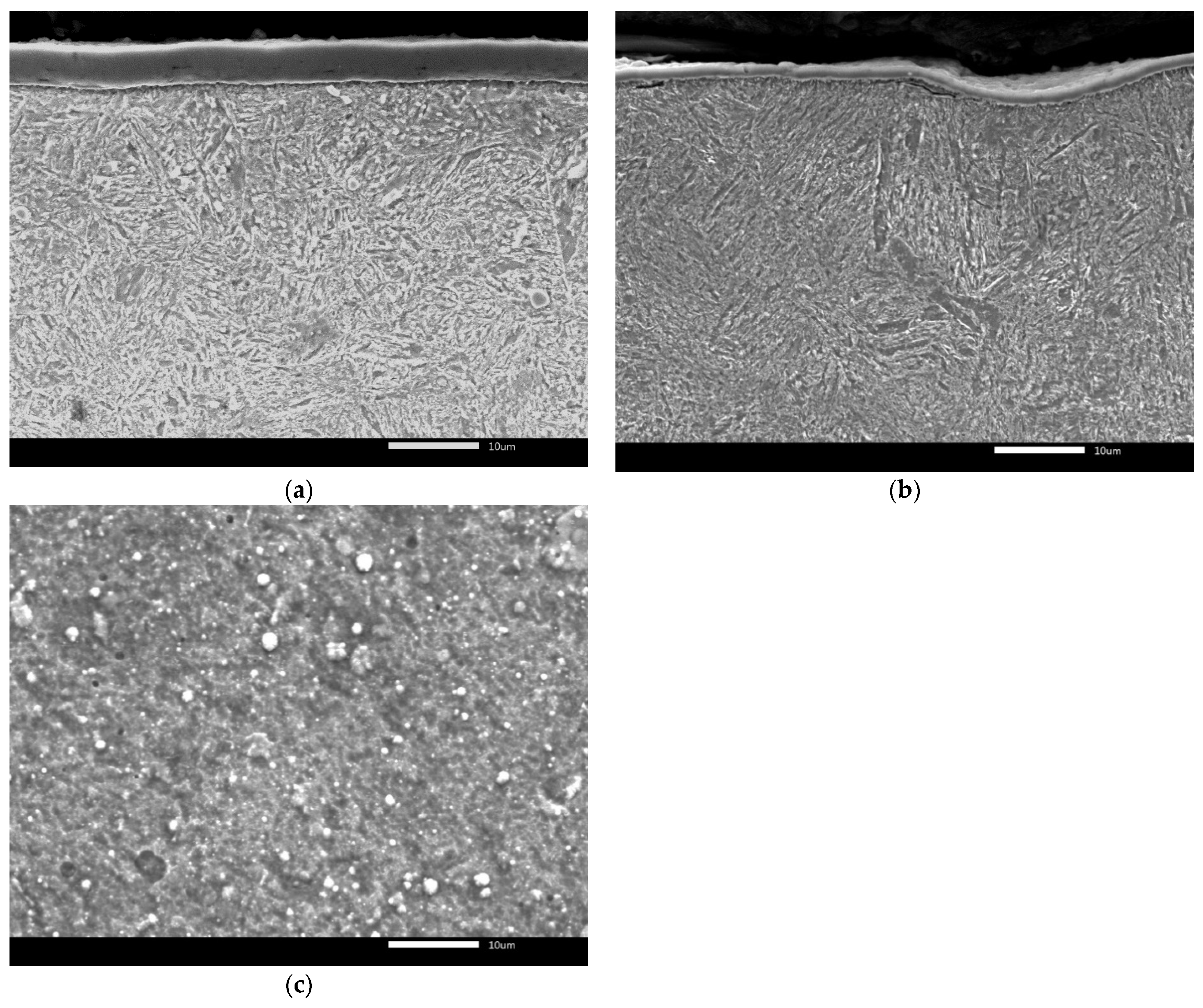
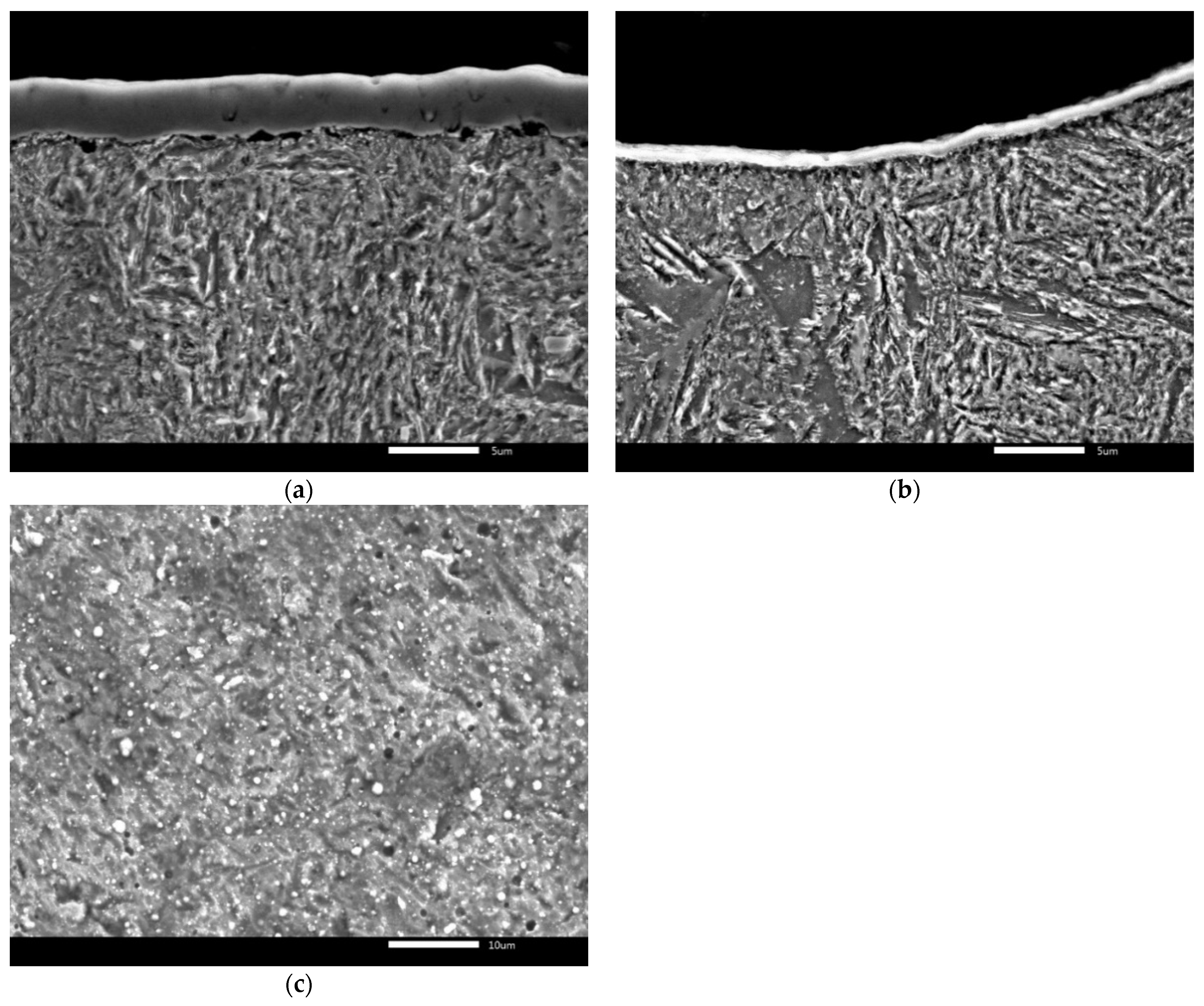
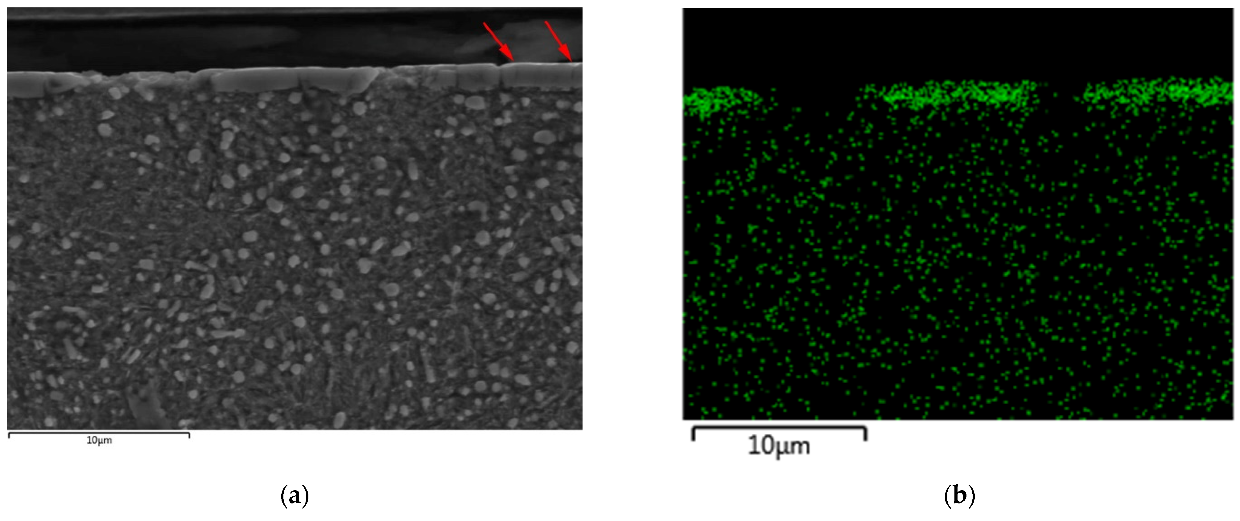
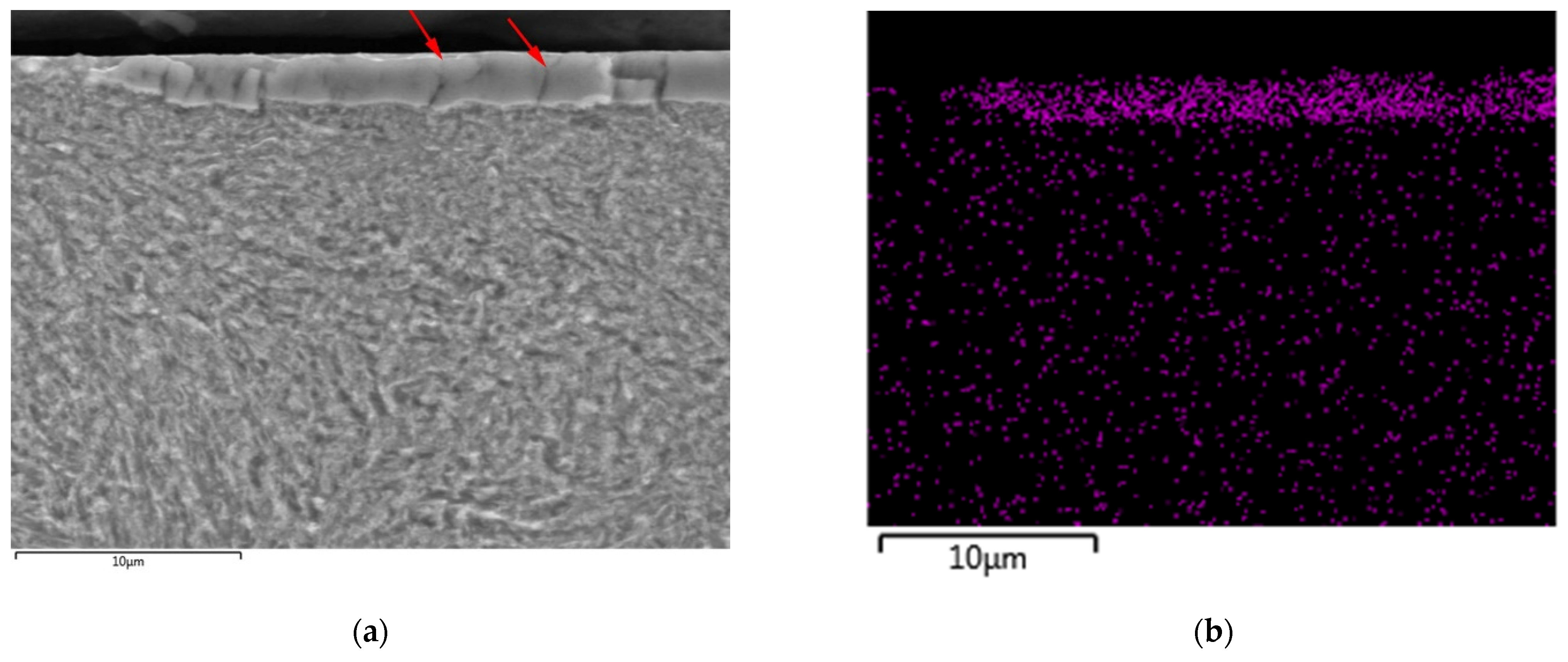
The thickness and surface of AlCrN and CrAlSiN layers are documented in Figure 3 and Figure 4, respectively. Both layers had the maximal thicknesses on tooth faces (Figure 3a and Figure 4a) and the thicknesses decreased towards the tooth flanks (Figure 3b and Figure 4b). Average thickness of the AlCrN layer was 5.3 µm on the tooth face and 1.2 µm on the tooth flank. Average thickness of the CrAlSiN layer was 3.7 µm on the tooth face and 0.7 µm on the tooth flank. Ragged surfaces of both layers can be seen in Figure 3c and Figure 4c. The maximal thickness of the layer on the plane tooth face is the consequence of the most favorable conditions for sputtering beam on this part of tooth. On other tooth parts, the access of the sputtering beam to the tooth surface is hindered by the evolving incurvature. These hindered sputtering conditions are the consequence of a decrease in layer thickness from the tooth face towards the tooth flank. The deposition parameters were chosen based on results and experience of operators of arc deposition PLATIT, Pi411 equipment, and they can be found in [41]. Lower thickness of the CrAlSiN layer was caused by higher number of sputtering targets used at deposition of the CrAlSiN layer in comparison with the AlCrN layer.
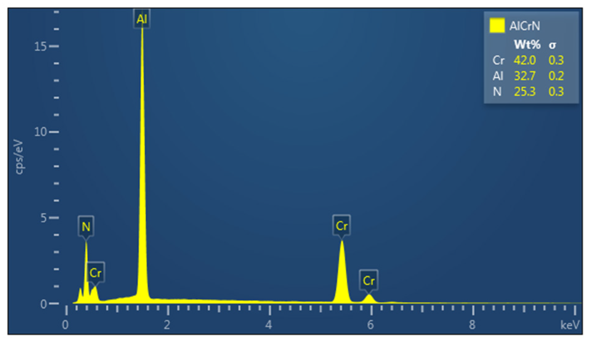
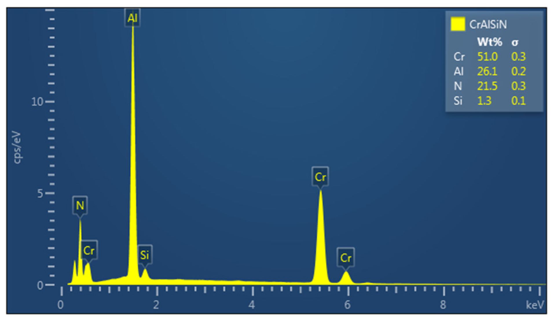
Chemical compositions of both layers were measured by EDS analysis. The EDS analysis of AlCrN layer in Figure 5 shows 40.0 wt.% of nitrogen, 32.7 wt.% of aluminum and 25.3 wt.% of chromium. The EDS analysis of CrAlSiN coating is in Figure 6. The concentrations of nitrogen, aluminum, chromium, and silicon in the CrAlSiN layer were 51.0, 26.1, 21.5, and 1.3 wt.%, respectively.
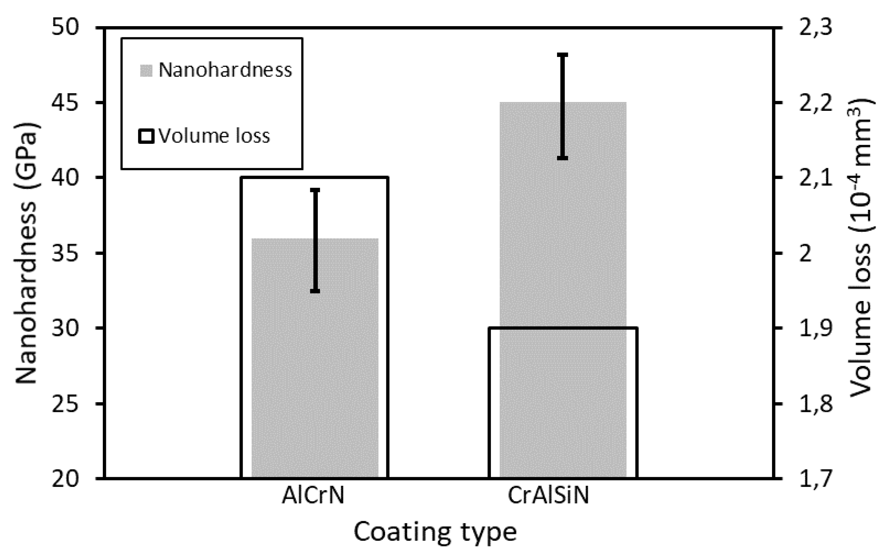
The results from nanohardness measurements and wear tests are compared for both coatings in Figure 7. The average nanohardness values of the AlCrN and CrAlSiN coatings were 36 and 45 GPa, respectively. The nanohardness values of both coatings match with volume losses measured at ball on disc wear tests. The volume loss of AlCrN layer is higher and its wear resistance is lower as the AlCrN layer is softer when compared with CrAlSiN layer.
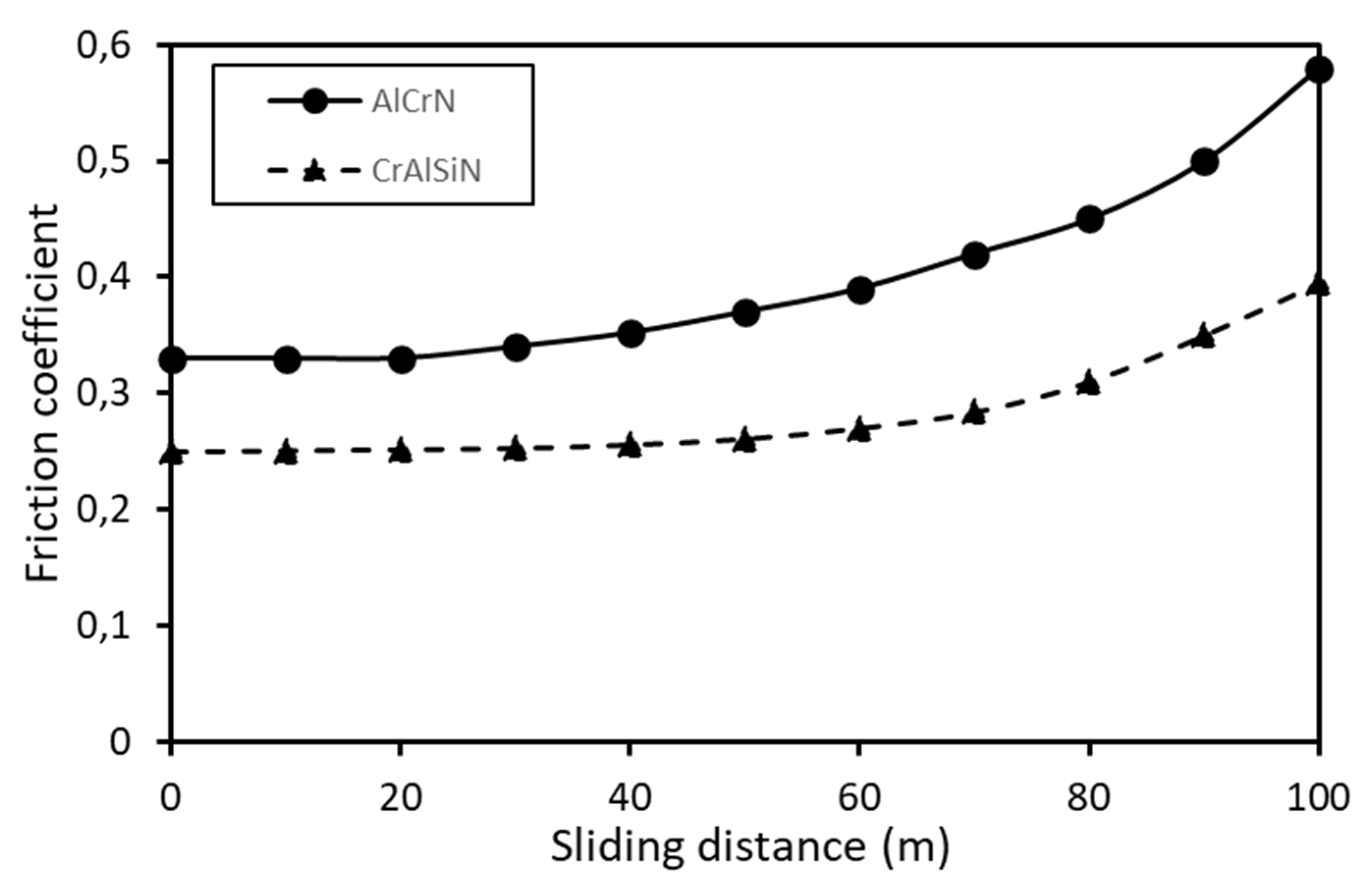
The development of the friction coefficient with the sliding distance for both coatings is shown in Figure 8. Stable friction coefficient value up to the sliding distance of 20 and 40 m can be seen for AlCrN and CrAlSiN coatings, respectively. Friction coefficient values increased after these sliding distances due to the wear of the tested coatings. The stable friction coefficient of the AlCrN coating (0.33) is higher compared to CrAlSiN coating (0.25). The CrAlSiN coating should offer higher wear resistance in gear mechanisms due to the lower friction coefficient, higher hardness, and lower wear of the CrAlSiN coating compared to the AlCrN coating.
3.2. Distribution of Load on Gear Tooth Surface
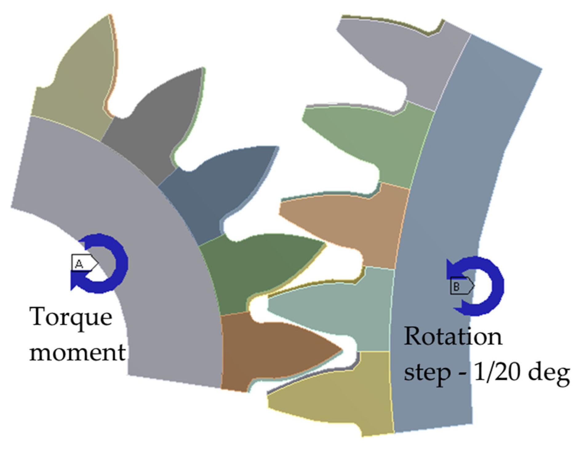
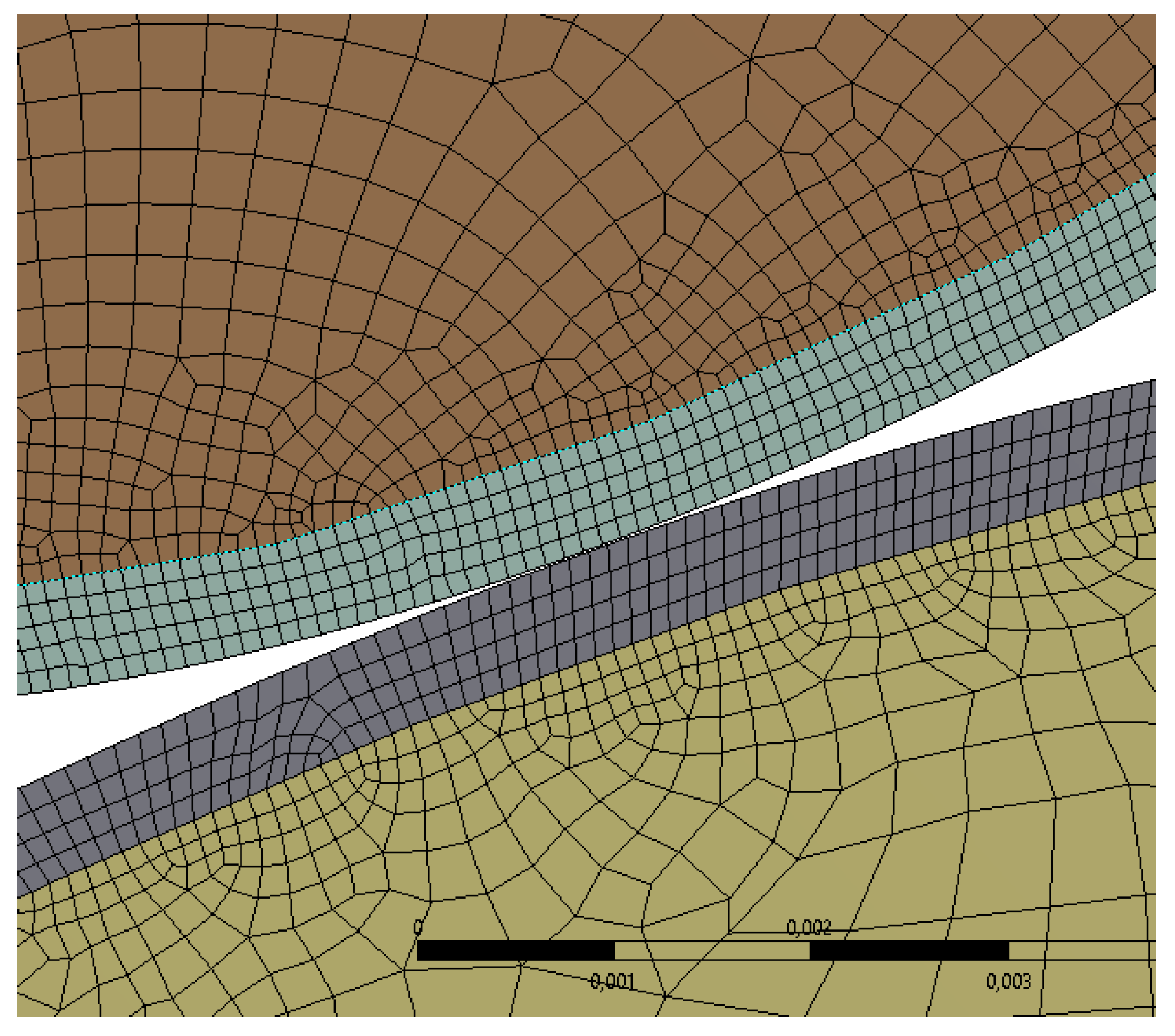
Distribution of stresses and contact pressures on the gear tooth surface during transmission of torque was simulated using the finite element method in ANSYS software. The static contact between the gear and pinion was simulated considering the simultaneous contact of meshing teeth using 3D finite element model. To obtain the stress–strain state over the entire surface of the tooth, the calculation was carried out in several positions of the gear and pinion, wherein each new calculation was performed when the gear was turned by an angle of 1/20°, which made it possible to obtain 100 design points along the entire investigated gear tooth surface. The computational model consisted of segments of gears that are in mesh, with five teeth on the gear and pinion, which is documented in Figure 9. A fine finite element mesh was created in the contact zone of the tooth with an element size (0.2 mm) comparable to the size of the contact patch. The thickness of this zone with a fine finite element mesh was 1 mm. The contact zone with a finite element is documented in Figure 10. Material properties of C55 steel were used in the finite element model, with a Young modulus of 2E11 Pa, Poisson’s ratio of 0.3, frictional coefficient of 0.05. The roughness of the contact surface was neglected during simulation as the contact pressure in the tested gear would not have differed significantly from the calculated ones, since the roughness of the contact surfaces of experimental gear was Ra below 0.8 µm. Different types of FEA elements were used for modelling in specific parts of gears. The CONTA174 and TARGE170 elements were used for modelling of contact faces. The SOLID186 element was chosen for the rest of the model gear. The COMBIN14 element was selected for soft contact between contact surfaces and the MPC184 FEA element was chosen for axial mounting gearwheels. The calculation was performed with 265,000 elements and 1.16 million nodes.
The distribution of contact pressure for HCR gears is depicted in Figure 11. The distribution of contact stresses on the tooth face in Figure 11 does not correspond with the distribution of contact force in Figure 2. It is caused by contact of teeth profiles with different radiuses in a given point of meshing.
Based on the results of previous experiments [15,16,17], the contact pressures on the gear tooth surface (tooth face, tooth pitch, and tooth flank) were calculated at the 10th, 11th, and 12th load stages during the Niemann test of HCR gears (Table 1).
From Table 1, it is evident that the highest contact pressures were calculated on the tooth flank and the lowest contact pressures on the tooth face. However, the difference in the stresses between tooth face and tooth pitch is insignificant due to the small difference between the radiuses of meshing profiles. High contact pressure (Table 1) and low thickness of layers (Figure 3b and Figure 4b) on the tooth flank indicate that tooth flanks are the most exposed areas of gear tooth surface. The distribution of frictional stresses along the gear tooth surface is depicted in Figure 12. The value of zero regarding frictional stresses on the tooth pitch is evident from Figure 12. The values of frictional stresses on the gear tooth surface at the 10th, 11th, and 12th load stages during Niemann tests of HCR gears are shown in Table 2. Low frictional stresses can be read from Table 2 even at the 12th load stage during the Niemann test. However, the highest frictional stresses were calculated in the most exposed areas on the tooth flank.
3.3. Macrostructure of Worn Gear Teeth
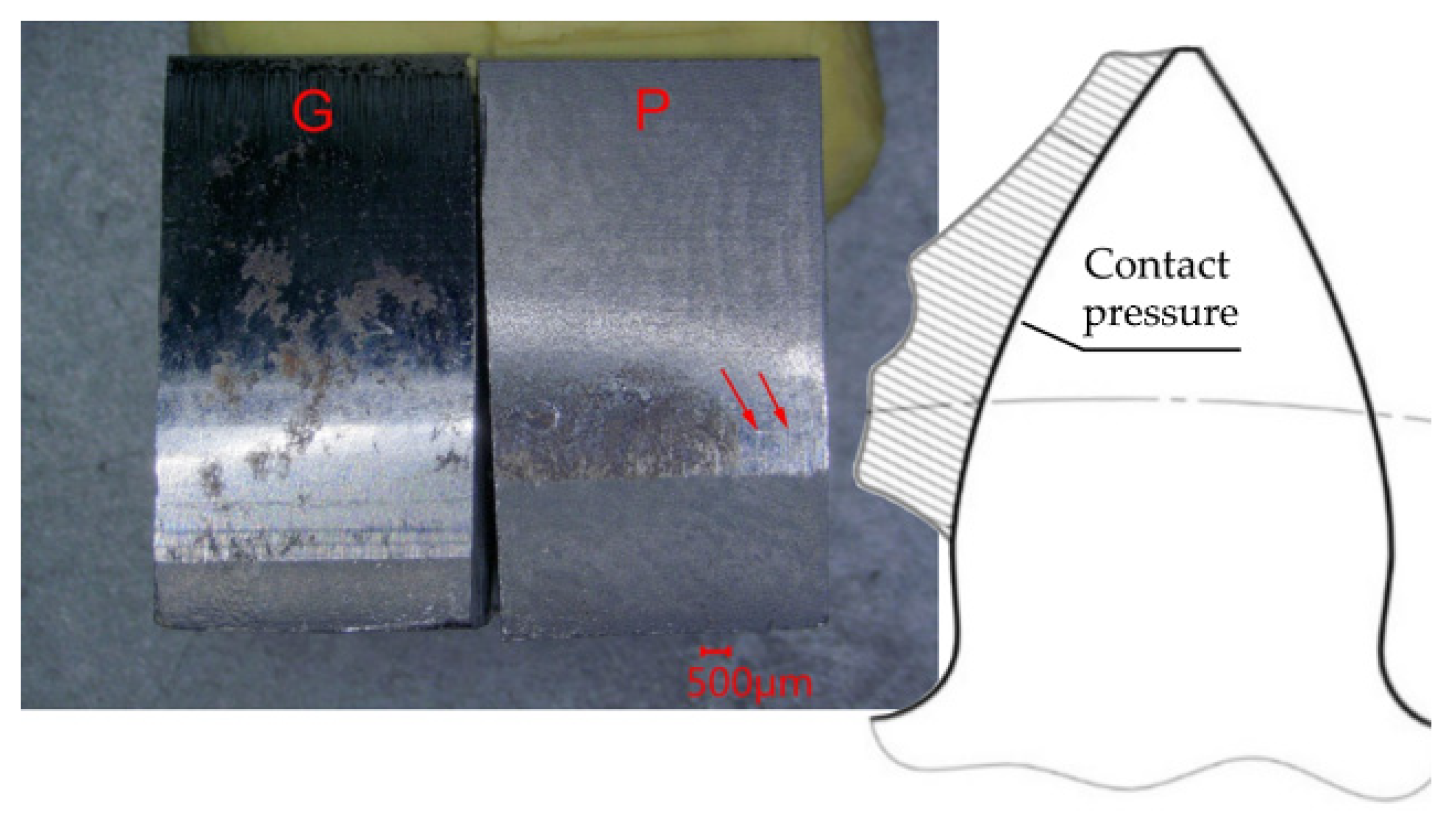
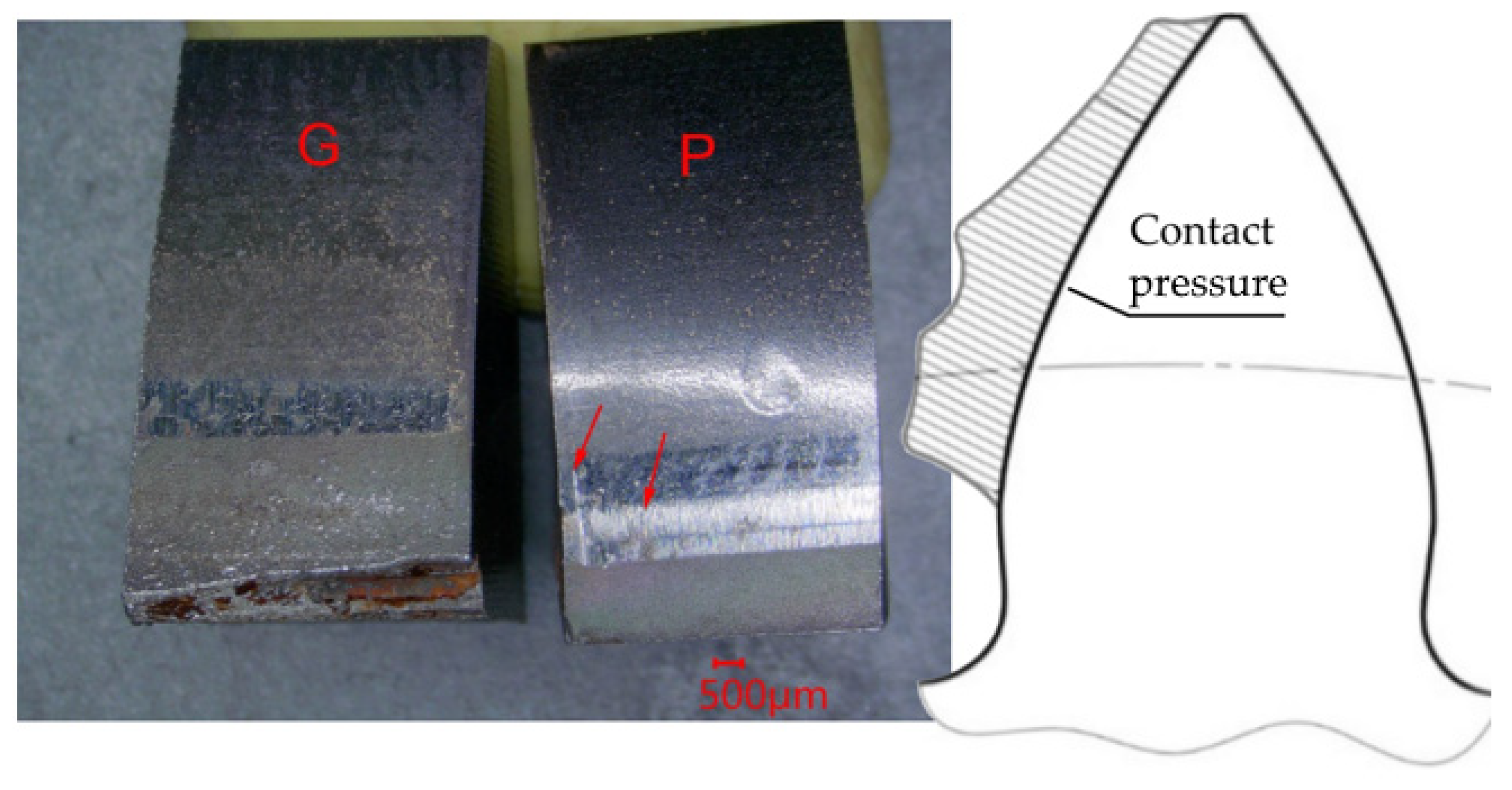
Worn gear tooth surfaces with AlCrN and CrAlSiN coatings and contact pressure distribution along the HCR gear tooth are shown in Figure 13 and Figure 14, respectively. The gear tooth (G) and pinion tooth (P) are indicated in these figures. The wear extent of gears (Gs) is smaller compared to pinions (Ps) in Figure 13 and Figure 14 due to more intensive load of pinions than gears. This is why the progression and mechanisms of wear were only studied on pinions. Worn pinion teeth showed similar characteristics with both types of coatings. Horizontal microcuts occurred in tooth flank regions (marked by red arrows) after the 12th load stage during Niemann tests. The microcutting is more intensive on the surface of the pinion with the CrAlSiN coating compared to the AlCrN coating. The areas on the tooth pitch were smoothed. The tooth face areas contain the rest of horizontal grooves created during chip machining of the gear tooth.
3.4. Temperature of Lubricants during the Niemann Test
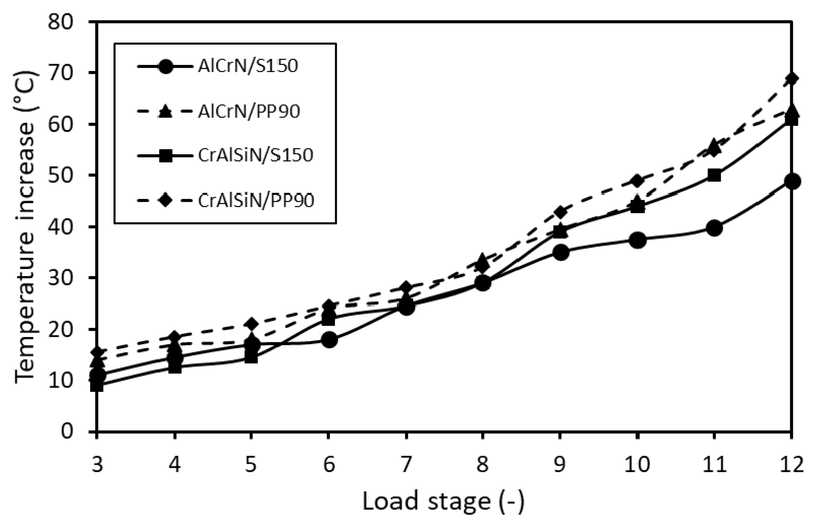
Suitability of a lubricant in a gear system can be evaluated by its temperature increase during load of the gear. Operating temperature of a lubricant should not excess 80 °C. The evolution of temperature for Biogear S150 and PP90 experimental oil is compared in Figure 15 during testing of gears with AlCrN and CrAlSiN coatings.
The temperature of Biogear S150 oil increased with the loading stage for both coatings in Figure 15. The temperature of the PP90 oil was higher at all load stages when compared to the Biogear S150 oil, but it did not exceed 70 °C after the 12th load stage. Based on the small effect of the oil type on the temperature increase, the next experiments were performed only with Biogear S150 oil.
3.5. Weight Loss of Gears during the Niemann Test
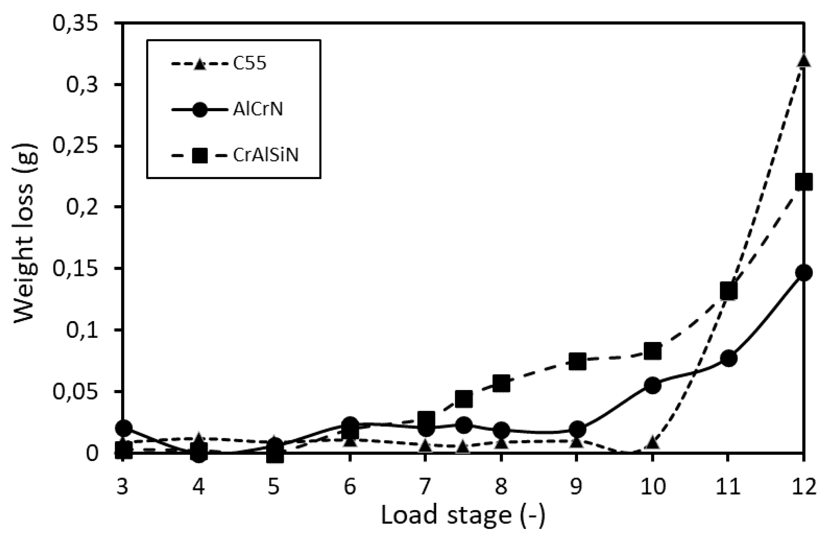
The progress in weight loss of the gear without coating (C55) and with AlCrN (AlCrN) and CrAlSiN (CrAlSiN) coatings are compared in Figure 16 in terms of dependence of load stage during the Niemann test. Both gears were tested in Biogear S150 oil. The weight loss exceeding 10 mg in two successive load stages represents the scuffing resistance of the gear. It was detected after the 11th load stage for the gear without a coating, which means resistance against scuffing up to the 10th load stage. The gear with the AlCrN coating reached the critical weight loss value after the 10th load stage, so the scuffing resistance is up to the ninth load stage. Accelerated wear of the gear with AlCrN coating after the ninth load stage is probably caused by gradual separation of the coating from the steel substrate from the tooth flank towards the tooth pitch while peeled fragments of AlCrN coating represented the increase in the weight loss of gear. For gear with CrAlSiN coating the weight loss exceeding 10 mg was registered after the eighth load stage, so the scuffing resistance up to the seventh load stage was determined. This is probably caused by gradual fragmentation and peeling of fragments of the thin CrAlSiN layer, first at flank region. Wear of the steel substrate in the area of peeled layer contributed to the significant wear of gear after the 10th load stage.
3.6. Roughness of Gear Tooth Surfaces
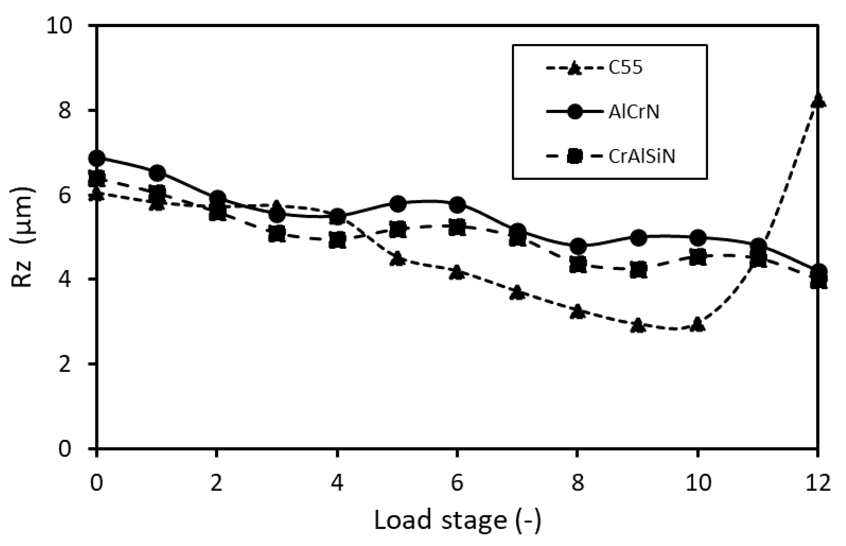
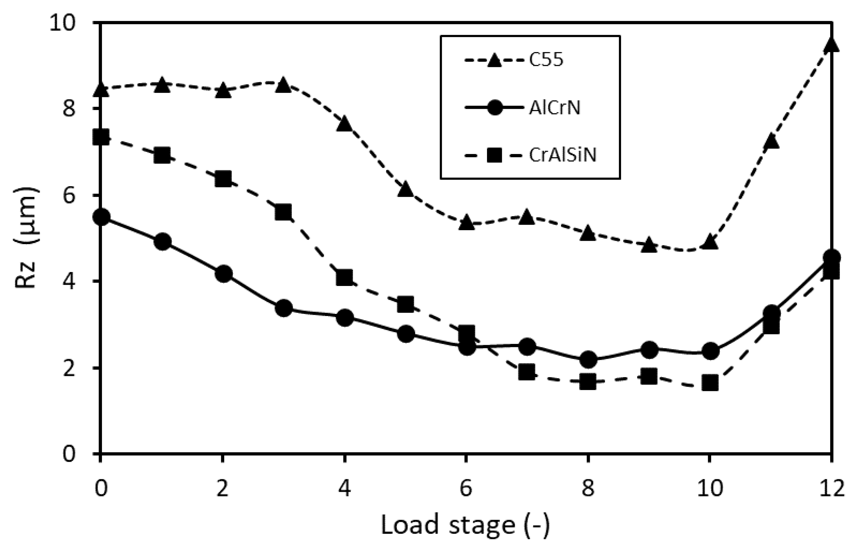
The weight loss is a proper criterion for evaluation of scuffing resistance at steady wear of gear, but it is not suitable for identifying local wear of coatings. The local wear was detected by measuring roughness on tooth face, pitch, and flank. The evolution of average values of maximal roughness Rz on tooth face is shown in Figure 17 in terms of dependence of the load stage for gear without (C55) and with AlCrN (AlCrN) and CrAlSiN (CrAlSiN) coatings. Figure 18 and Figure 19 show the development of average roughness Rz on tooth pitch (Figure 18) and tooth flank (Figure 19) in terms of dependence of load degree for gear without (C55) and with AlCrN (AlCrN) and CrAlSiN (CrAlSiN) coatings. All points plotted in Figure 17, Figure 18 and Figure 19 are the average values calculated of 10 measurements.
The roughness on tooth face of coated gears in Figure 17 decreased slightly over the whole test, but it increased for noncoated gear after the 10th load stage of the Niemann test. All average roughness values of coated gears were below the critical value of 7 µm. The last roughness value of noncoated gear exceeded 7 µm, which means that the tooth face of noncoated gear does not guarantee the resistance against the scuffing at the 12th load stage of the Niemann test.
The development of roughness on tooth pitch of all gears in Figure 18 slightly decreased up to the fifth load stage. In the interval from the 5th to 10th load stage, the roughness decreased more rapidly. The decrease in roughness was the consequence of smoothing of surface protrusions during tooth meshing. After the 10th load stage, the roughness of coated gears increased slightly, with all values below the critical value of 7 µm. The roughness of noncoated gear increased rapidly after the 10th load stage and it exceeded the critical value of 7 µm after the 11th load stage of the Niemann test.
The roughness on the tooth flank of the noncoated gear in Figure 19 was significantly higher compared to coated values at all measured load stages. High roughness values on the tooth flank of the noncoated gear, exceeding the criterion of 7 µm from the beginning of the test up to the fourth load stage, were the consequence of imprecision during chip machining of the gear. When testing in the interval from the 5th to 10th load stage, the roughness decreased below the critical value in consequence of smoothing of surface protrusions during tooth meshing. The roughness increased rapidly after the 10th load stage and exceeded the critical value of 7 µm after the 11th load stage. The roughness on the tooth flank of coated gears decreased from the start of the test up to the eighth load stage and measured values of both coatings intersected. After the eighth load stage, the roughness of coated gears increased. The average values of roughness did not exceed the critical value of 7 µm, but individual measurements exceeded 7 µm at the 12th load stage.
For all tested gears, increased roughness values at the test start are the consequence of chip machining of the gears. Subsequent roughness decrease is caused by smoothing of surface protrusions of the surface layer. The final increase in roughness at the test end is caused by wear of layer at the increased load stage. Based on the test results, the noncoated gear can be considered resistant against scuffing up to the 10th load stage of the Niemann test. The AlCrN and CrAlSiN coatings guarantee the resistance of HCR gears against wear by scuffing up to the 11th load stage of the Niemann test.
3.7. Microstructure of Worn Gear Teeth
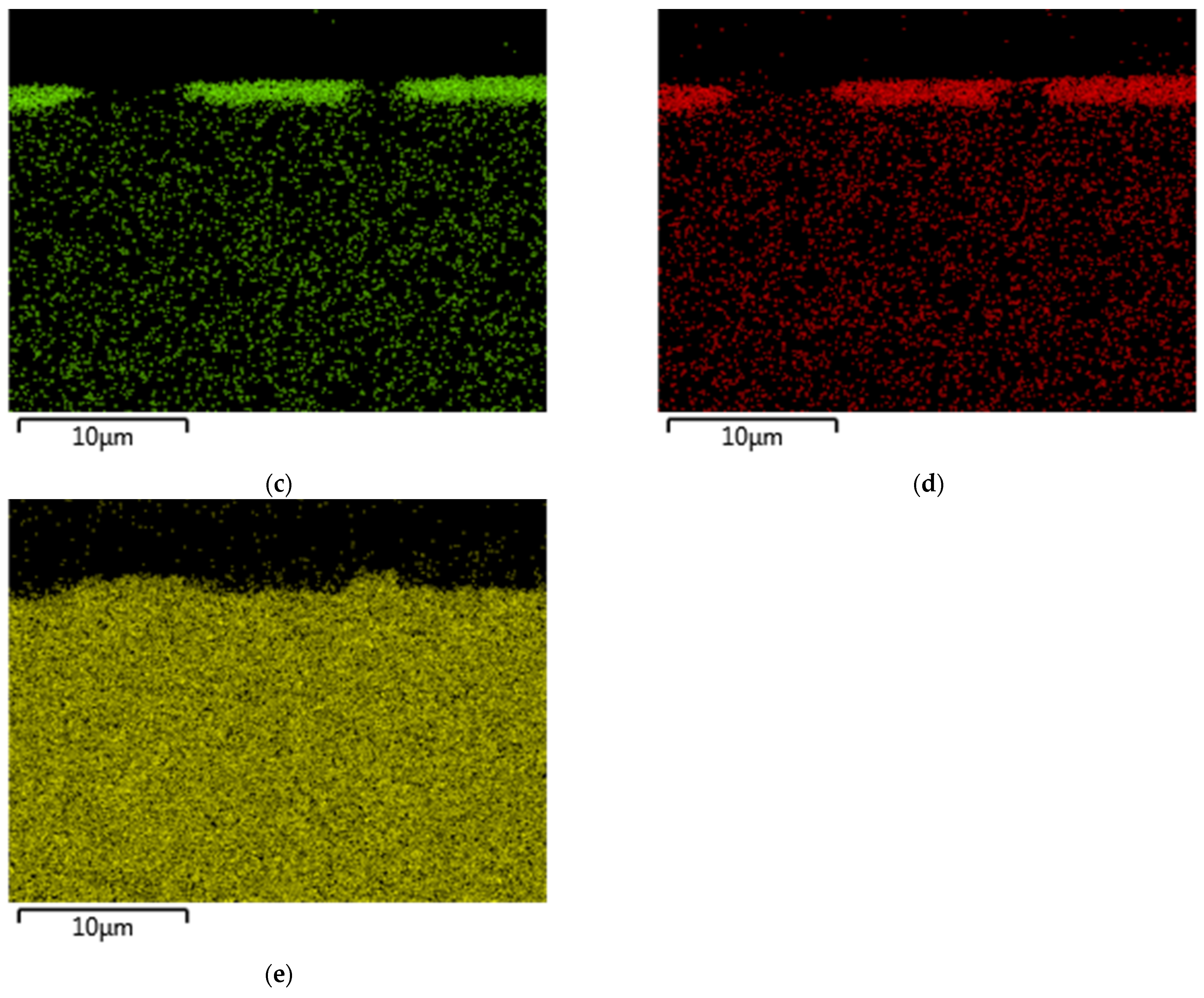
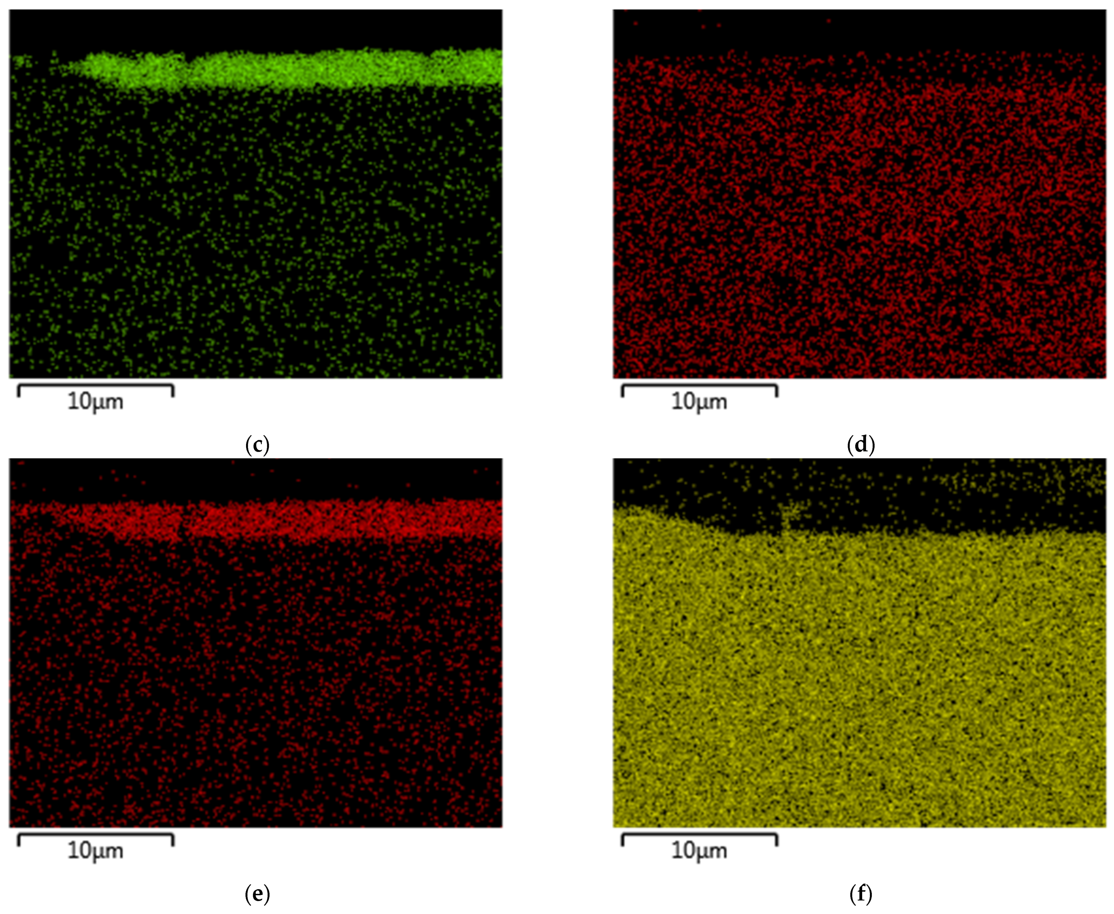
Figure 20 and Figure 21 depict the cross-section of teeth with AlCrN and CrAlSiN coatings and distribution of elements in both layers, respectively. The cross-sections of both teeth document the interface between the worn layer and steel substrate after finishing the Niemann test. Booth interfaces were located near tooth pitch. The area distribution of elements creating the layers (Figure 20 and Figure 21) highlights locations of damaged coatings. The area distribution of Fe represents the steel substrate of gears. Some cracks are visible in layers and marked by red arrows in Figure 20a and Figure 21a. Cracked layers fragmented, and some fragments peeled subsequently. High contact pressure on gear tooth surface (Table 1) facilitated gradual peeling of layers from the steel substrate, despite low frictional stress (Table 2).
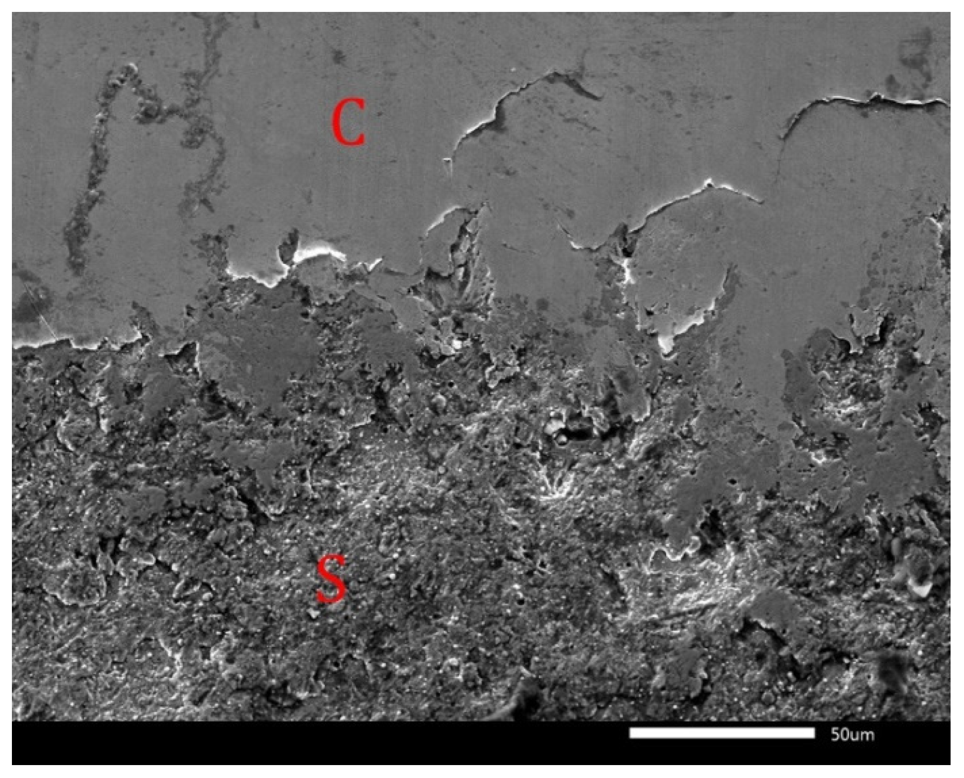
The fragmentation and peeling of layers are evident from Figure 22, where the interface between the depleted AlCrN coating (C) and steel substrate (S) is documented. The peeling of coatings is indicated by weight loss in Figure 16. In areas where the layer was removed, significant wearing of steel substrate occurred. This was demonstrated by microcutting of steel substrate on tooth flank, which was more intensive for the CrAlSiN coating (Figure 14) than for the AlCrN coating (Figure 13).
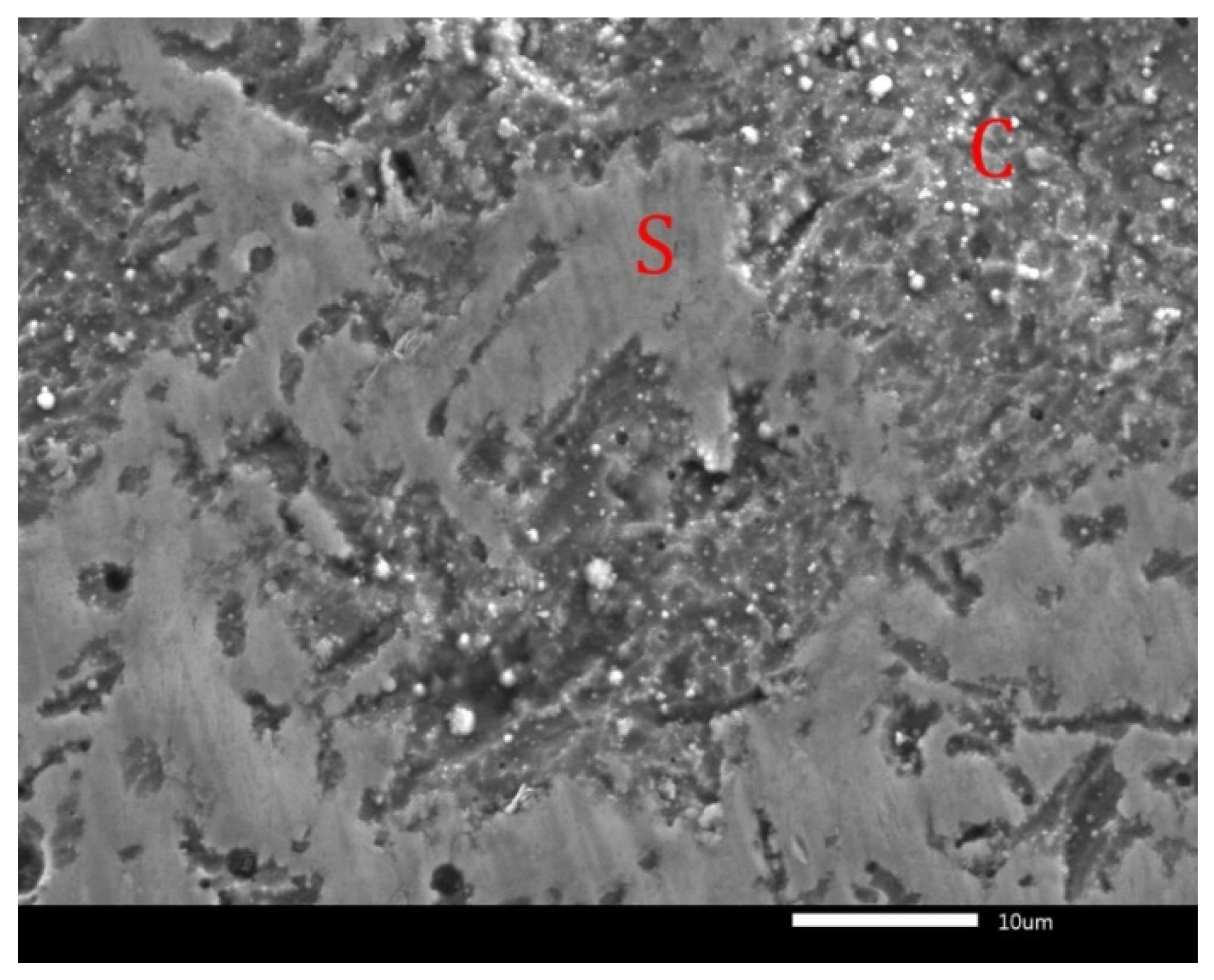
While the coatings were completely removed on the tooth flank, discontinuous areas of coatings were observed on the tooth pitch. Low thickness of the deponed CrAlSiN coating (1.8–2.5 µm) on the tooth pitch caused more intensive wear compared to the AlCrN coating, with a thickness of 2.4–2.9 µm on the tooth pitch. An almost compact region on the tooth pitch with the AlCrN coating is documented in Figure 23. In this figure, smoothing and subsequent cracking (marked by red arrows) of the depleted layer (C) can be seen. The AlCrN layer was removed only in few locations.
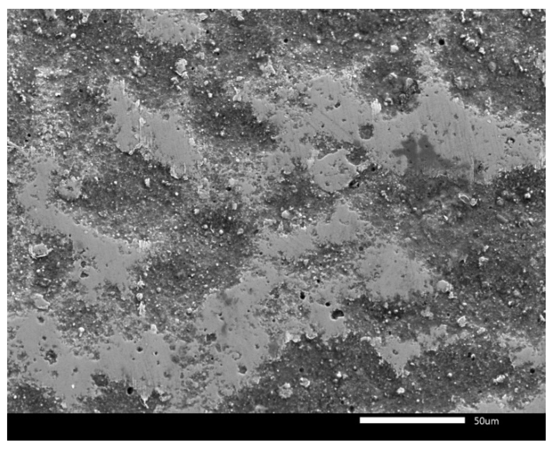
A discontinuous AlCrN coating (C) and steel substrate (S) on tooth pitch are documented in Figure 24. Plastically deformed substrate spread on the coating surface (Figure 24), which contributed to the decrease in roughness on the tooth pitch.
The lowest wear was measured on the tooth face. The surface of worn AlCrN coating on tooth face is shown in Figure 25. In this figure, a compact layer can be seen, but protrusions of the deponed layer were smoothed during the tests, which is confirmed by the roughness degrease on the tooth face with the graduated load stage in Figure 17.
Wear of gear tooth with CrAlSiN coating showed similar characteristics on tooth face, pitch, and flank as wear in the case of AlCrN coating and therefore it was not documented in detail. Literary sources [16,17,18,19] presume longer lifetime of CrAlSiN coatings than AlCrN coatings. Values of hardness, wear resistance and friction coefficient should confirm these presumptions. However, in our experiments CrAlSiN coating worn more significantly than AlCrN coating. The reason for this is lower thickness of this layer. The layers with thicknesses below 2 μm cracked during experiments, and consequently they wore more quickly compared to thicker layers. The CrAlSiN coating consisted of a significantly higher ratio of sections with thicknesses below 2 μm compared to the AlCrN coating.
Total resistance of coated gears against scuffing was represented by a roughness Rz below 7 µm after the 12th load stage of the Niemann test was not achieved in our experiments. The critical roughness was exceeded in individual cases after the 12th load stage of the Niemann test for both coatings. The reason for this is significant wear of tooth flank, which was caused by fast removal of relatively thin coatings and subsequent wear of the steel substrate. Thereafter, microcutting of substrate was observed, and this caused an increase in roughness Rz above the critical value of 7 µm in individual cases.
Complete resistance on the whole gear tooth surface, including tooth flank, against wear by scuffing could be achieved by deposition of a uniform coating with a thickness over 2.5 µm. Therefore, in the next experiments it will be necessary to modify deposition parameters of coatings—for example, by prolongation of the deposition time or by increase in nitrogen pressure.
4. Conclusions
Nonstandard involute gears with two types of coatings, AlCrN and CrAlSiN, were tested using a Niemann tester at graduated load up to the 12th load stage and compared to noncoated gears. Both Biogear S150 gear oil and PP90 universal hydraulic oil were applied during these tests. Resistance of gears against wear by scuffing was evaluated on the basis of maximal roughness of worn surface Rz when exceeding the value of 7 µm. Based on the Niemann test results, simulation of load of gears and observation of worn gear teeth following conclusion can be confirmed.
The maximal contact pressure of 1350 MPa was calculated at the maximal, the 12th, load stage in regions of tooth flank, where the lowest coating thickness was measured. Maximal frictional stress of 10 MPa was calculated in tooth flank regions too.
During the evaluation of wear of gear teeth, a positive effect of applied coatings was observed. Deponed layers decreased the wear of coated gears compared to gears without a coating. The critical roughness value was exceeded after the 10th load stage of Niemann test for gears without a coating. For gears with AlCrN and CrAlSiN coatings, it was exceeded after the 11th load stage during the Niemann test.
Both experimental oils, Biogear S150 and PP90, proved suitable during the Niemann tests as their temperatures did not exceed the limit value of 80 °C.
Wear of AlCrN and CrAlSiN coatings had similar characters. The coatings cracked in areas of low coating thickness due to the application of contact pressure during tooth meshing. Subsequently cracked layers disintegrated and fragments of layers detached from the steel substrate. The layer wore predominantly on the tooth flank where the thinnest layer was observed and where maximal contact pressure was calculated. After the removal of the thin layer on the tooth flank, the substrate was worn by microcutting, which caused significant increase in its roughness. At the tooth pitch region, the surface protrusions of coatings were smoothed. Later, the coatings cracked but peeled only locally. On the tooth face, the surface protrusions of applied coatings were smoothed during the tests, but the coatings remained compact during the whole test.
Total resistance of coated gears against wearing by scuffing could be achieved by deposition of uniform coating with a thickness over 2.5 µm on the whole gear tooth surface, including the tooth flank.
Author Contributions
Conceptualization, P.Š., M.B. and E.G.; methodology, P.Š.; software, R.P.; validation, M.B., E.G. and P.Š.; investigation, F.T.; resources, E.G.; data curation, P.Š.; writing—original draft preparation, E.G.; writing—review and editing, P.Š.; visualization, R.P.; supervision, P.Š.; project administration, M.B. All authors have read and agreed to the published version of the manuscript.
Funding
This work was supported by the Grant Agency of the Ministry of Education of the Slovak Republic within the project VEGA 1/0130/19 Possibilities for the preparation and application of particle composites from waste materials and with the support of the University Research Park STU Bratislava, ITMS 26240220084.
Conflicts of Interest
The authors declare no conflict of interest. The funders had no role in the design of the study; in the collection, analyses or interpretation of data; in the writing of the manuscript or in the decision to publish the results.
References
- Vereš, M.; Bošanský, M.; Gaduš, J. Theory of Convex-Concave and Plane Cylindrical Gearing; STU Bratislava: Bratislava, Slovakia, 2006; ISBN 80-227-2451-3. [Google Scholar]
- Ziaran, S.; Darula, R. Determination of the State of Wear of High Contact Ratio Gear Sets by Means of Spectrum and Cepstrum Analysis. J. Vib. Acous. 2013, 135, 021008. [Google Scholar] [CrossRef]
- Goldfarb, V.; Trubachev, E.; Barmina, N. Advanced Gear Engineering; Springer: Basel, Switzerland, 2018; ISBN 978-3-319-60398-8. [Google Scholar]
- Qiu, L.S.; Zhu, X.D.; Xu, K.V. Internal stress on adhesion of hard coatings synthesized by multi arc ion platting. Surf. Coat. Technol. 2017, 332, 267–274. [Google Scholar] [CrossRef]
- Liu, J.; Xu, Y.; Pan, G. A combined acoustic and dynamic model of a defective ball bearing. J. Sound Vib. 2021, 501, 116029. [Google Scholar] [CrossRef]
- Hutchings, I.; Shipway, P. Tribology Friction and Wear of Engineering Materials, 2nd ed.; University of Cambridge: Cambridge, UK, 2017; ISBN 978-0-08-100910-9. [Google Scholar]
- Bhushan, B. Modern Tribology Handbook. Principles of Tribology; The Ohio State University: Columbus, OH, USA, 2001; ISBN 0-8493-8403-6. [Google Scholar]
- Persson, B.N.J. Contact mechanics for randomly rough surfaces. Surf. Sci. Rep. 2006, 61, 201–227. [Google Scholar] [CrossRef] [Green Version]
- Rusnák, J. Štúdium tribologických vlastností materiálov nanesených na povrch nekonvenčnými technológiami; SPU Nitra: Nitra, Slovakia, 2005; ISBN 80-8069-485-0. [Google Scholar]
- Nowak, D.; Januszewicz, B.; Niedzielski, P. Morphology, mechanical and tribological properties of hybrid carbon layer fabricated by Radio Frequency Plasma Assisted Chemical Vapor Deposition. Surf. Coat. Technol. 2017, 329, 1–10. [Google Scholar] [CrossRef]
- Ju, H.; He, X.; Yu, L.; Xu, J. The microstructure and tribological properties at elevated temperatures of tungen silicon nitride films. Surf. Coat. Technol. 2017, 326, 255–263. [Google Scholar] [CrossRef]
- Domínguez, A.S.; Bueno, J.P.; Torres, I.Z.; López, M.M. Characterization and corrosion resistance of electroless black Ni-P coatings of double black layer on carbon steel. Surf. Coat. Technol. 2017, 326, 192–199. [Google Scholar] [CrossRef]
- Li, Y.; He, Y.; Xiu, J.; Wang, W.; Zhu, Y.; Hu, B. Wear and corrosion properties of AlSi 420 martensitic stainless steel treated by active screen plasma nitriding. Surf. Coat. Technol. 2017, 329, 184–190. [Google Scholar] [CrossRef]
- Vanya, A. Návrh štruktúry Deponovanej Ako Systému “Povlak-bok Zuba” z Hľadiska Požiadaviek Vybraného Ozubeného Prevodu–Dizertačná Práca; STU SjF: Bratislava, Slovakia, 2012. [Google Scholar]
- Gondár, E.; Bošanský, M.; Repková, J.; Toth, F. The carrying capacity of TiCN coating on convex-concave (C-C) gearings. Mod. Mach. Sci. J. 2018, 18, 2633–2638. [Google Scholar] [CrossRef]
- Gondár, E.; Bošanský, M.; Rusnák, J.; Toth, F.; Repková, J. The Application of DLC Coating on Convex-Concave (C-C) Gearings. Manuf. Technol. 2019, 19, 930–935. [Google Scholar] [CrossRef]
- Bošanský, M.; Gondár, E.; Švec, P.; Toth, F.; Protasov, R. A Study of Wear in Thin Coatings Applied to Convex-Concave Gearings. Lubricants 2020, 8, 56. [Google Scholar] [CrossRef]
- Mo, J.L.; Zhu, M.H.; Leyland, A.; Matthews, A. Impact wear and abrasion resistance of CrN, AlCrN and AlTiN PVD coatings. Surf. Coat. Technol. 2013, 215, 170–177. [Google Scholar] [CrossRef]
- Xiao, B.; Li, H.; Mei, H.; Dai, W.; Yuo, F.; Wu, Z.; Wang, Q. A study of oxidation behavior of AlTiN- and AlCrN- based multilayer coatings. Surf. Coat. Technol. 2018, 333, 229–237. [Google Scholar] [CrossRef]
- Wang, L.; Nie, X.; Housden, J.; Span, E.; Jiang, J.C.; Meletis, E.I.; Leyland, A.; Matthews, A. Material transfer phenomena and failure mechanisms of a nanostructured Cr-Al-N coating in laboratory wear tests and an industrial punch tool application. Surf. Coat. Technol. 2008, 203, 816–821. [Google Scholar] [CrossRef]
- Wang, L.; Zhang, G.; Wood, R.J.K.; Xue, Q. Fabrication of CrAlN nanocomposite films with high hardness and excellent anti-wear performance for gear application. Surf. Coat. Technol. 2010, 204, 3517–3524. [Google Scholar] [CrossRef]
- Chang, Y.Y.; Amrutwar, S. Effect of Plasma Nitriding Pretreatment on the Mechanical Properties of AlCrSiN-Coated Tool Steels. Materials 2019, 12, 795. [Google Scholar] [CrossRef] [Green Version]
- Kim, S.K.; Le, V.V.; Vinh, V.V.; Lee, J.W. Effect of cathode arc current and bias voltage on the mechanical properties of CrAlSiN thin films. Surf. Coat. Technol. 2008, 202, 5400–5404. [Google Scholar] [CrossRef]
- Zhang, S.; Wang, L.; Wag, Q.; Li, M. A superhard CrAlSiN superlattice coating deposited by multi-arc ion platting: I. Microstructure and mechanical properties. Surf. Coat. Technol. 2013, 214, 160–167. [Google Scholar] [CrossRef]
- Polcar, T.; Cavaleiro, A. High-temperature tribological properties of CrAlN, CrAlSiN and AlCrSiN coatings. Surf. Coat. Technol. 2011, 206, 1244–1251. [Google Scholar] [CrossRef]
- Holzschuh, H. Chemical-vapor deposition of wear resistant hard coatings in the Ti-B-C-N system: Properties and metal-cutting tests. International. J. Refract. Met. Hard Mater. 2002, 20, 143–149. [Google Scholar] [CrossRef]
- Bobzin, K. High-performance coatings for cutting tools. CIRP J. Manuf. Sci. Technol. 2017, 18, 1–9. [Google Scholar] [CrossRef]
- Gronostajski, Z.; Kaszuba, M.; Widomski, P.; Smolik, J.; Ziemba, J.; Hawryluk, M. Analysis of wear mechanisms of hot forging tools protected with hybrid layers performed by nitriding and PVD coatings deposition. Wear 2019, 420–421, 269–280. [Google Scholar] [CrossRef]
- Podgornik, B.; Zajec, B.; Bay, N.; Vižintin, J. Application of hard coatings for blanking and piercing tools. Wear 2011, 270, 850–856. [Google Scholar] [CrossRef]
- Leskovšek, V.; Podgornik, B.; Jenko, M. A PACVD duplex coating for hot-forging applications. Wear 2009, 266, 453–460. [Google Scholar] [CrossRef]
- Santecchia, E.; Hamouda, A.M.S.; Musharavati, F.; Erfan Zalnezhad, E.; Marcello Cabibbo, M.; Spigarelli, S. Wear resistance investigation of titanium nitride-based coatings. Ceram. Int. 2015, 41, 9A. [Google Scholar] [CrossRef]
- Aliofkhazraei, M.; Ali, N. PVD Technology in Fabrication of Micro- and Nanostructured Coatings (Book Chapter). In Comprehensive Materials Processing; Elsevier: Amsterdam, The Netherlands, 2014; Volume 7, ISBN 978-0-08-096533-8. [Google Scholar]
- Chen, Y.; Du, H.; Chen, M.; Yang, J.; Xiong, J.; Zhao, H. Structure and wear behavior of AlCrSiN-based coatings. Appl. Surf. Sci. 2016, 370, 176–183. [Google Scholar] [CrossRef]
- Brizuela, M.; Garcia-Luis, A.; Braceras, I.; Oñate, J.I.; Sánchez-López, J.C.; Martínez-Martínez, D.; López-Cartes, C.; Fernández, A. Magnetron sputtering of Cr(Al)N coatings: Mechanical and tribological study. Surf. Coat. Technol. 2005, 200, 192–197. [Google Scholar] [CrossRef]
- Yu, C.; Tian, L.; Wei, Y.; Wang, S.; Li, T.; Xu, B. The effect of substrate bias voltages on impact resistance of CrAlN coatings deposited by modified ion beam enhanced magnetron sputtering. Appl. Surf. Sci. 2009, 255, 4033–4038. [Google Scholar] [CrossRef]
- Beblein, S.; Breidenstein, B.; Denkena, B.; Pusch, C.; Hoche, H.; Oechsner, M. Thermomechanical Coating Load in Dependence of Fundamental Coating Properties. Procedia CIRP 2017, 58, 25–30. [Google Scholar] [CrossRef] [Green Version]
- Chen, Y.; Zhang, Z.; Yuan, T.; Mei, F.; Lin, X.; Gao, J.; Chen, W.; Xu, Y. The synergy of V and Si on the microstructure, tribological and oxidation properties of AlCrN based coatings. Surf. Coat. Technol. 2021, 412, 127082. [Google Scholar] [CrossRef]
- Sun, S.Q.; Ye, Y.W.; Wang, Y.X.; Liu, M.Q.; Liu, X.; Li, J.L.; Wang, L.P. Structure and tribological performances of CrAlSiN coatings with different Si percentages in seawater. Tribol. Int. 2017, 115, 591–599. [Google Scholar] [CrossRef]
- Chang, Y.Y.; Weng, S.Y.; Chen, C.H.; Fu, F.X. High temperature oxidation and cutting performance of AlCrN, TiVN and multilayered AlCrN/TiVN hard coatings. Surf. Coat. Technol. 2017, 332, 494–503. [Google Scholar] [CrossRef]
- Polcar, T.; Cavaleiro, A. High temperature properties of CrAlN, CrAlSiN and AlCrSiN coatings—Structure and oxidation. Mater. Chem. Phys. 2011, 129, 195–201. [Google Scholar] [CrossRef]
- Martan, J.; Beneš, P. Thermal properties of cutting tool coatings at high temperatures. Thermochim. Acta 2012, 539, 51–55. [Google Scholar] [CrossRef]
- Lukaszkowicz, K.; Czyżniewski, A.; Kwaśny, W.; Pancielejko, M. Structure and mechanical properties of PVD coatings deposited onto the X40CrMoV5-1 hot work tool steel substrate. Vacuum 2012, 86, 1186–1194. [Google Scholar] [CrossRef]
- Chen, M.; Chen, W.; Cai, F.; Zhang, S.; Wang, Q. Structural evolution and electrochemical behaviors of multilayer Al-Cr-Si-N coatings. Surf. Coat. Technol. 2016, 296, 33–39. [Google Scholar] [CrossRef] [Green Version]
- Cai, F.; Gao, Y.; Zhang, S.; Zhang, L.; Wang, Q. Gradient architecture of Si containing layer and improved cutting performance of AlCrSiN coated tools. Wear 2019, 424–425, 193–202. [Google Scholar] [CrossRef]
- Rodríguez-Barrero, S.; Fernández-Larrinoa, J.; Azkona, I.; López de Lacalle, L.N.R.; Polvorosa, R. Enhanced Performance of Nanostructured Coatings for Drilling by Droplet Elimination. Mater. Manuf. Process. 2016, 31, 593–602. [Google Scholar] [CrossRef]
- Fernández-Abia, A.I.; Barreiro, J.; de Lacalle, L.N.L.; González-Madruga, D. Effect of mechanical pre-treatments in the behaviour of nanostructured PVD-coated tools in turning. Int. J. Adv. Manuf. Tech. 2014, 73, 1119–1132. [Google Scholar] [CrossRef]
- Álvarez, Á.; Calleja, A.; Ortega, N.; De Lacalle, L.N.L. Five-Axis Milling of Large Spiral Bevel Gears: Toolpath Definition, Finishing, and Shape Errors. Metals 2018, 8, 353. [Google Scholar] [CrossRef] [Green Version]
- ISO 14635-1:2000. Gears—FZG Test Procedures; International Organization for Standardization: Geneva, Switzerland, 2000. [Google Scholar]
- ASTM D5182-19. Standard Test Method for Evaluating the Scuffing Load Capacity of Oils (FZG Visual Method); ASTM International: West Conshohocken, PA, USA, 2019. [Google Scholar]
- Rusnák, J.; Kadnár, M.; Kučera, M. Biologicky Odbúrateľné Oleje; SPU Nitra: Nitra, Slovakia, 2009; ISBN 978-80-552-0166-5. [Google Scholar]
- Zienkiewicz, O.C.; Taylor, R.L. The Finite Element Method for Solid and Structural Mechanics, 6th ed.; Elsevier: Amsterdam, The Netherlands, 2005; ISBN 978-0-7506-6321-2. [Google Scholar]
- Kurowski, P.M. Finite Element Analysis for Design Engineers, 2nd ed.; SAE International: Warrendale, PA, USA, 2017; ISBN 978-0-7680-8369-9. [Google Scholar]
- Terleeva, P.; Slonova, A.I.; Rogov, A.B.; Yerokhin, A. Wear resistant coatings with a high friction coefficient produced by plasma electrolytic oxidation of Al alloys in electrolytes with basalt mineral powder additions. Materials 2019, 12, 2738. [Google Scholar] [CrossRef] [Green Version]
- Mahade, S.; Narayan, K.; Govindarayan, S.; Bjorklund, S.; Curry, N.; Joshi, S. Exploiting Suspension Plasma Spraying to Deposit Wear-Resistant Carbide Coatings. Materials 2019, 12, 2344. [Google Scholar] [CrossRef] [PubMed] [Green Version]
- Zhang, B.; Liu, H.; Bai, H.; Zhu, C.; Wu, W. Ratchetting-multiaxial fatigue damage analysis in gear rolling contacts considering tooth surface roughness. Wear 2019, 428–429, 137–146. [Google Scholar] [CrossRef]
- Chang, H.; Borghesani, P.; Smith, W.A.; Peng, Z. Application of surface replication combined with image analysis to investigate wear evolution on gear teeth—A case study. Wear 2019, 430–431, 355–368. [Google Scholar] [CrossRef]
Figure 1.
The normal force distribution for LCR gear.

Figure 2.
The HCR gear normal force distribution and spots for coating evaluation.

Figure 3.
Cross section of tooth with AlCrN coating on tooth face (a) and tooth flank (b), surface of AlCrN coating (c).
Figure 3.
Cross section of tooth with AlCrN coating on tooth face (a) and tooth flank (b), surface of AlCrN coating (c).

Figure 4.
Cross-section of tooth with AlCrN coating on tooth face (a) and tooth flank (b), surface of CrAlSiN coating (c).
Figure 4.
Cross-section of tooth with AlCrN coating on tooth face (a) and tooth flank (b), surface of CrAlSiN coating (c).

Figure 5.
EDS analysis of AlCrN coating.

Figure 6.
EDS analysis of CrAlSiN coating.

Figure 7.
Nanohardness and volume loss of AlCrN and CrAlSiN coatings.

Figure 8.
Development of friction coefficient with sliding distance for AlCrN and CrAlSiN coatings.

Figure 9.
The model gear with the applied load and constraints.

Figure 10.
The finite elements in the contact zone.

Figure 11.
Contact pressure distribution along HCR gear tooth.

Figure 12.
Frictional stress distribution along the gear tooth.

Figure 13.
Wear of gear (G) and pinion (P) with the AlCrN coating and contact pressure distribution along the HCR gear tooth.
Figure 13.
Wear of gear (G) and pinion (P) with the AlCrN coating and contact pressure distribution along the HCR gear tooth.

Figure 14.
Wear of gear (G) and pinion (P) with the CrAlSiN coating and contact pressure distribution along the HCR gear tooth.
Figure 14.
Wear of gear (G) and pinion (P) with the CrAlSiN coating and contact pressure distribution along the HCR gear tooth.

Figure 15.
Temperature of Biogear S150 (S150) and PP90 (PP90) oils during Niemann tests of gears with AlCrN and CrAlSiN coatings.
Figure 15.
Temperature of Biogear S150 (S150) and PP90 (PP90) oils during Niemann tests of gears with AlCrN and CrAlSiN coatings.

Figure 16.
Weight loss of gear without (C55) and with AlCrN and CrAlSiN coatings.

Figure 17.
Roughness Rz on tooth face for gear tooth without (C55) and with AlCrN and CrAlSiN coatings.
Figure 17.
Roughness Rz on tooth face for gear tooth without (C55) and with AlCrN and CrAlSiN coatings.

Figure 18.
Roughness Rz on tooth pitch for gear tooth without (C55) and with AlCrN and CrAlSiN coatings.
Figure 18.
Roughness Rz on tooth pitch for gear tooth without (C55) and with AlCrN and CrAlSiN coatings.

Figure 19.
Roughness Rz on tooth flank for gear tooth without (C55) and with AlCrN and CrAlSiN coatings.
Figure 19.
Roughness Rz on tooth flank for gear tooth without (C55) and with AlCrN and CrAlSiN coatings.

Figure 20.
EDS analysis of the tooth cross-section with AlCrN coating—distribution of elements: (a) cross-section of tooth with AlCrN layer (SEM); (b) area distribution of N; (c) area distribution of Al; (d) area distribution of Cr; (e) area distribution of Fe.
Figure 20.
EDS analysis of the tooth cross-section with AlCrN coating—distribution of elements: (a) cross-section of tooth with AlCrN layer (SEM); (b) area distribution of N; (c) area distribution of Al; (d) area distribution of Cr; (e) area distribution of Fe.


Figure 21.
EDS analysis of the tooth cross-section with CrAlSiN coating—distribution of elements: (a) cross-section of tooth with CrAlSiN layer (SEM); (b) area distribution of N; (c) area distribution of Al; (d) area distribution of Si; (e) area distribution of Cr; (f) area distribution of Fe.
Figure 21.
EDS analysis of the tooth cross-section with CrAlSiN coating—distribution of elements: (a) cross-section of tooth with CrAlSiN layer (SEM); (b) area distribution of N; (c) area distribution of Al; (d) area distribution of Si; (e) area distribution of Cr; (f) area distribution of Fe.


Figure 22.
The interface between the AlCrN coating (C) and steel substrate (S).

Figure 23.
Cracked AlCrN coating (C) with local areas of steel substrate (S) on tooth pitch.

Figure 24.
Steel substrate (S) spread on the AlCrN coating (C) on tooth pitch.

Figure 25.
Worn AlCrN coating on tooth face.


Table 1.
Contact pressure on HCR gear tooth at different load stages.
| 10th Load Stage | 11th Load Stage | 12th Load Stage | |
|---|---|---|---|
| Tooth face | 766 MPa | 925 MPa | 1100 MPa |
| Tooth pitch | 815 MPa | 960 MPa | 1170 MPa |
| Tooth flank | 940 MPa | 1130 MPa | 1350 MPa |
Table 2.
Frictional stresses on HCR gear tooth at different load stages.
| 10th Load Stage | 11th Load Stage | 12th Load Stage | |
|---|---|---|---|
| Tooth face | 5.5 MPa | 6.7 MPa | 8 MPa |
| Tooth pitch | 0 MPa | 0 MPa | 0 MPa |
| Tooth flank | 6.9 MPa | 1.1 MPa | 10 MPa |
Publisher’s Note: MDPI stays neutral with regard to jurisdictional claims in published maps and institutional affiliations. |
© 2021 by the authors. Licensee MDPI, Basel, Switzerland. This article is an open access article distributed under the terms and conditions of the Creative Commons Attribution (CC BY) license (https://creativecommons.org/licenses/by/4.0/).
Share and Cite
MDPI and ACS Style
Švec, P.; Bošanský, M.; Gondár, E.; Toth, F.; Protasov, R. Wear of AlCrN and CrAlSiN Coatings Applied to Nonstandard Involute Gears. Lubricants 2021, 9, 54. https://0-doi-org.brum.beds.ac.uk/10.3390/lubricants9050054
AMA Style
Švec P, Bošanský M, Gondár E, Toth F, Protasov R. Wear of AlCrN and CrAlSiN Coatings Applied to Nonstandard Involute Gears. Lubricants. 2021; 9(5):54. https://0-doi-org.brum.beds.ac.uk/10.3390/lubricants9050054
Chicago/Turabian StyleŠvec, Pavol, Miroslav Bošanský, Ernest Gondár, František Toth, and Roman Protasov. 2021. "Wear of AlCrN and CrAlSiN Coatings Applied to Nonstandard Involute Gears" Lubricants 9, no. 5: 54. https://0-doi-org.brum.beds.ac.uk/10.3390/lubricants9050054
Note that from the first issue of 2016, this journal uses article numbers instead of page numbers. See further details here.