Effect of Coating and Low Viscosity Oils on Piston Ring Friction under Mixed Regime of Lubrication through Analytical Modelling


Machine Design Laboratory, Department of Mechanical Engineering and Aeronautics, University of Patras, 26504 Patras, Greece
Lubricants 2021, 9(12), 124; https://0-doi-org.brum.beds.ac.uk/10.3390/lubricants9120124
Submission received: 20 November 2021
/
Revised: 12 December 2021
/
Accepted: 15 December 2021
/
Published: 17 December 2021
Abstract
:This paper presents the impact of coating topography in piston ring-liner conjunction under mixed regime of lubrication using low viscosity oils. The study provides a time efficient analytical model including mixed-hydrodynamics regime of lubrication under different contact conditions. The method modified the expressions of the contact load and area of Greenwood-Tripp model in order to capture the real asperities interaction into contact. The model represents the tribological behavior of a thin top ring at Top Dead Centre, where boundary and mixed conditions are predominant. Electroplated CrN and PVD TiN coated rings were studied to predict the ring friction. The results are compared with an uncoated steel ring. The CrN coating shows slighter coefficient of friction, due to the coating morphology and roughness parameters. The TiN coating presents thicker lubricant films and higher coefficient of friction because the surface topography is quite rough with high peaks. This can be explained because of the major contribution of the roughness parameter and asperity slope in the boundary friction prediction.
1. Introduction
The ever-increasing fleet of cars, motorcycles, buses and heavy-duty vehicles leads to environmental implications due to increased CO2 emissions. An important innovation in this respect is the view of ecological tribology, which aims to minimize the environmental footprint of the Internal Combustion (IC) engine. The reduction of toxic emissions and fuel consumption are the main keys in the development of high-performance engines [1]. A recent study presented by the European Commission has showed that new technologies of road vehicles using automation and electrification may improve pollutant emissions according to the new generation of Euro 6 [2].
Today, high-performance engines are being downsized whilst maintaining their highest firing pressures. This trend increases the overall thermal and mechanical stresses on engine components, such as pistons, piston rings and cylinder bores [3]. An understanding of ring topography and coating characteristics is significant to improve fuel consumption and the environmental regulations, such as the Euro emission standards [4,5]. The piston ring-liner contact operate with a lubricant oil under different lubrication regimes during piston motion. Generally, the nature of lubrication is mixed at piston reversals (TDC and BDC) and hydrodynamic at mid-stroke [6]. The thin surface of top compression ring can produce high friction and wear owing to the tight contact between the piston and cylinder wall [7]. Practically, the interaction between the piston-ring pack and the cylinder liner has complicated tribological and wear behavior due to the rapid variations of pressure, speed and lubricant temperature [8,9]. Therefore, the transient nature of ring-liner lubrication should be investigated. Some initial studies including mixed conditions, blow-by and twist effects were conducted by Furuhama [10,11] and Tian et al. [12]. Their results for rigid piston rings complied with the experimental findings using different type of engines. A mathematical model using Patir and Cheng approach [13], asperity interactions and gas-blow by was also reported by Wolff [14], who assumed different ring-pack configurations. It was found that the number of the rings can alter the tribological and blow-by behaviour of contacts in a marine engine. Accurate prediction of minimum film thickness and frictional losses is important to avoid cylinder pressure loss and improve efficiency. Priest et al. [15] and Chong et al. [16] reported the impact of boundary conditions within the contact during ring motion. These studies explain how the input flow conditions and operating conditions affect minimum lubricant film and friction (viscous and boundary). With respect to the lubricant behavior, Nouri et al. [17] and Taylor et al. [18] described how the cavitation flow, lubricant rheology and engine speed affect ring friction and film predictions. It was found that mixed regime of lubrication can lead to higher frictional loss as the ring tends to piston reversals. Additionally, the move to low viscosity oils can help fuel economy by reducing engine friction by 10%. The effect of the ring design and topography on friction was also studied by Morris et al. [19] and Söderfjäll et al. [20], with the latter showing measurements for the impact of the tangential load in the oil-control ring tribological performance. For this reason, the most conventional solution to protect the surface and operation of piston rings are coatings.
Key research has been conducted for many years in the field of coatings and lubricants. The strategy used by engine manufacturers has been the deposition of a layer of a material with high wear resistance [21]. For a long time, the piston rings used hard chrome electroplating surfaces. Therefore, it is recommended that ring coatings can evenly distribute heat and avoid scuffing [22]. Diamond-like carbon, multi-layered and thermal spray coatings have also been used in powertrain system by other authors [23,24,25]. These promising methods have been applied to improve high temperature-wear resistance and corrosion. Despite the potential of these materials on wear enhancement, more investigation (numerical and experimental) is necessary for further development, such as heat removal, scuffing and the reduction of friction. Igartua et al. [26] used several coated piston rings, including nano-HVOF coating, electrolytic NiPCO + Si3N4 as well as PVD multilayer coating and TiN/CrN layer. The tests were subjected to fired engine conditions using a turbo diesel engine. The nano-HVOF coating liner was shown to perform best regarding fuel consumption. Zabala et al. [27] suggested that the type of lubricant and coating topography have a great effect on friction coefficient in the boundary or mixed regime of lubrication. In this manner, Gore et al. [28] presented how a Nickel-Silicon Carbide wear-resistant coating react in piston ring-liner conjunction using a sliding tribometer. The experimental predictions were compared with an analytical model, which can be used as a tool to predict tribological quantities such as the friction and film thickness with very well accuracy. Dolatabadi et al. [29] also noted the impact of coating on cylinder bore surface. They analysed and discussed the importance of coating materials on the global fuel economy and emission of the engine, through multi-physics modelling of ring dynamics, contact tribology and thermal effects. Zavos and Nikolakopoulos [30,31] explored the effect of ring coating on local displacements into the minimum film thickness and, simultaneously, created a contact model between the ring and liner including surface roughness. The positive role of analytical models and tribometer tests when used as tools to understand the mechanisms of tribofilm formation along the coated surface is dominant. Taylor [32] studied the impact of ring motion with “squeeze” effect using several ring profiles and low viscosity oils. It was found that ring profile and oil viscosity influence asperity friction at dead centres, which can motivate automotive companies. Tomanik et al. [33] tested some real coated specimens of the ring-liner conjunction lubricated with low viscosity oils, which are now used in high-performance IC engines. The study explains in detail the influence of the topography combined with the type of lubricant on engine friction and CO2 emissions.
Despite a significant number of reports, the main question remains related to the choice of piston ring coating for the boundary or mixed regimes of lubrication and high loads, as the ring tends to piston reversals (TDC and BDC respectively). The current paper attempts to address the issues of ring friction for electroplated CrN and PVD TiN coatings using a time efficient approach. The analytical method includes mixed-hydrodynamic lubrication, surface properties and lubricant rheology. Two low viscosity synthetic oils were used, and each oil was studied at temperature of 120 °C. To replicate the mixed regime of lubrication of the thin piston ring at TDC reversal, the reference coatings were analysed using the applied load of 60 N, as well as the sliding velocity were varied in the range of 0.5–1.16 m/s. The topography of the coated piston rings was measured in this analysis using a microscopy, an ambient atomic force microscope and a portable profilometer. Recently, a detailed numerical and experimental approach by Zavos and Nikolakopoulos [34] reported the effect of thin ring profile and surface roughness on boundary friction at TDC. Therefore, this paper extends the influence of “coating-lubricant” subsystem on friction through analytical modelling including the asperities may come into contact.
2. Analytical Modelling
2.1. Description of Piston Ring-Liner Contact
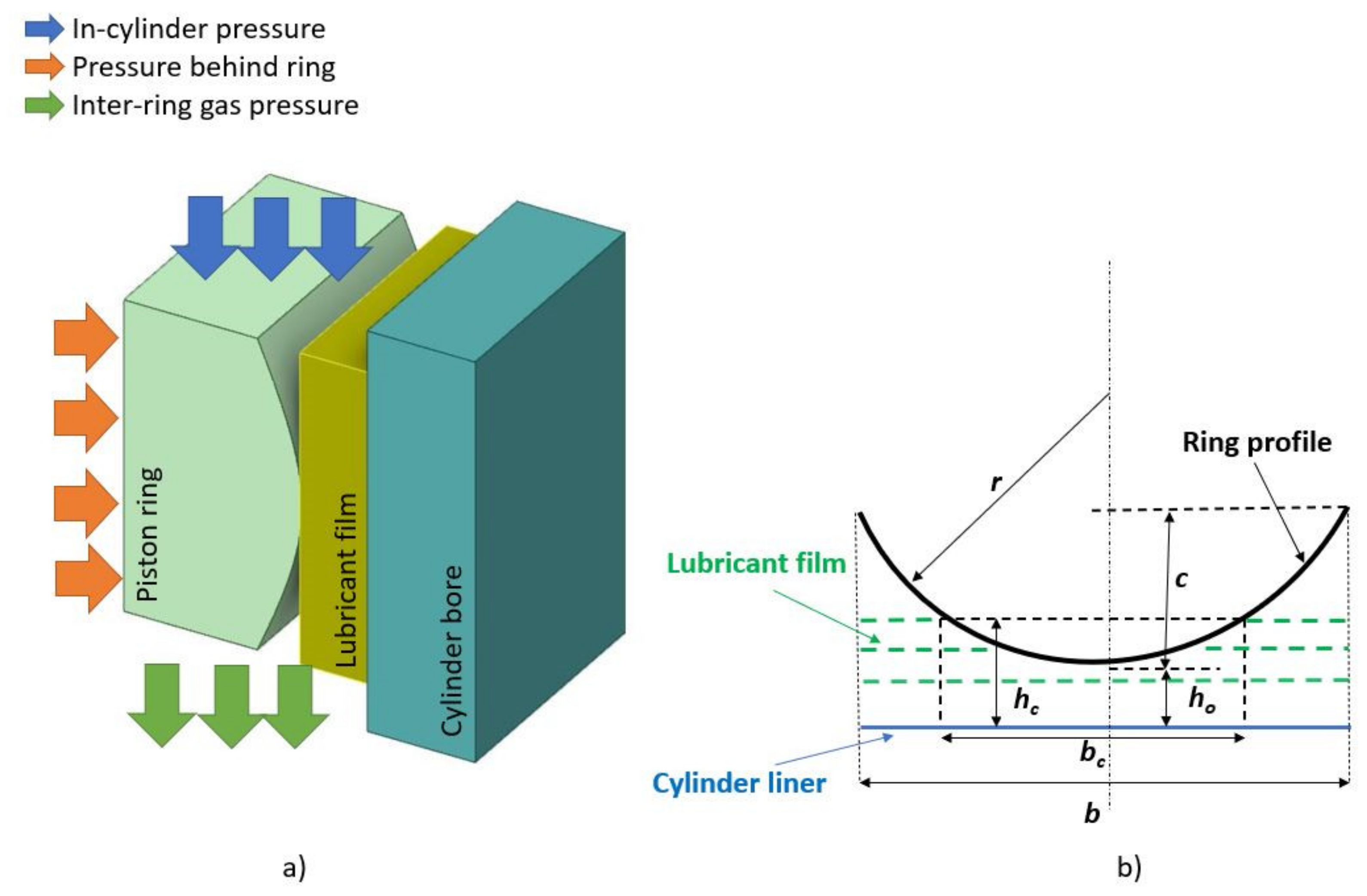
The interface between the ring and liner has a thin film of oil where the lubrication conditions are changed rapidly from mixed to hydrodynamics during the piston stroke as the in-cylinder pressure varies. The piston ring-liner contact with the basic parameters is shown in Figure 1.
The film thickness h(x) can be expressed as:
where is the minimum film, is the ring profile and is the local contact deformation. The ring profile is not ideal parabolic caused significant changes in the contact [34]. Assuming a symmetric parabolic profile, it is beneficial because the various integrals which appear in the following equations can be solved algebraically, and this can help to solve the proposed model faster. Of course, including the real ring profile in the equations, the analysis would become slower. Consequently, in this study, a symmetric parabolic shape was used as follows:
The ring curvature or crown height can be given as relation of the contact face-width radius:
where c is the ring curvature or crown height and b is the ring-face width. With regard to the local contact deformation, the classical Hertzian theory can be used. Gore and Rahnejat [35] represent an analytical expression of a rigid ellipsoidal solid loaded against a semi-infinite elastic half-space such as the piston ring and the cylinder bore surfaces:
where F is the applied load, L is the ring length in the lateral direction, r is the ring radius of curvature and E* is the equivalent Young’s modulus of elasticity. Table 1 provide the specifications of the mechanical properties of the piston ring and their coating layers. For the cases studied here, the ring surfaces were furnished with coatings of electroplated CrN and PVD TiN, respectively. The base material of the ring was stainless steel 6D125 from the manufacturer. An uncoated aluminium cylinder bore was also considered in the current analysis.
Using the input load of 60 N, the maximum local deformation was limited (δ ≈ 0.06 μm) and therefore, for this study, the lubrication conditions are boundary or mixed and full hydrodynamic in the ring-liner interface.
2.2. Determination of Load by Lubricant Film
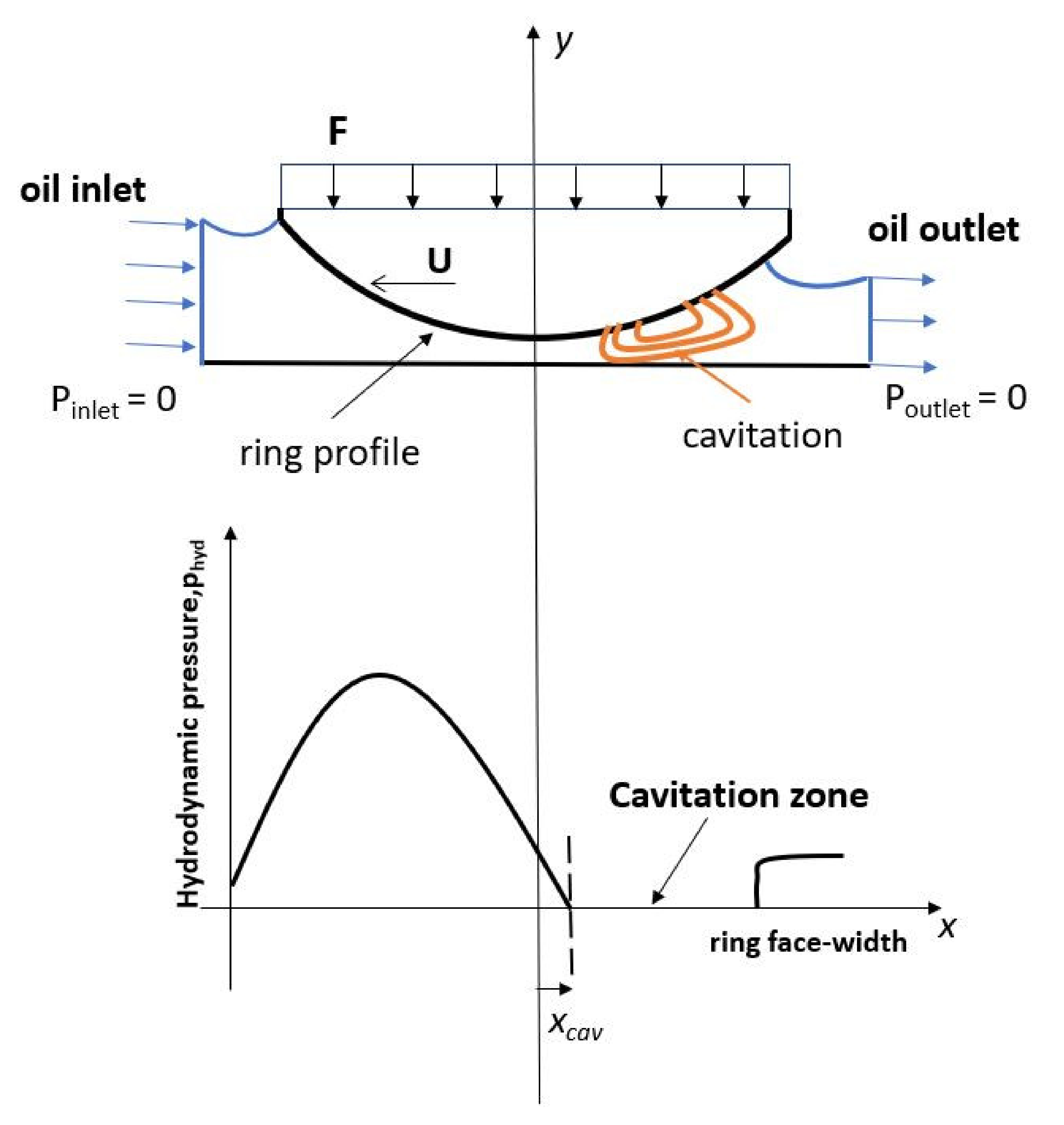
As mentioned before, the maximum local deformation is very low within the contact, therefore, the ring profile is supported by the lubricant film under hydrodynamic lubrication. The generated pressures are also insufficient to generate any piezo-viscous action in the lubricant. Consequently, the analysis assumes here an iso-viscous lubricant under isothermal conditions. The pressure distribution is evaluated using full film inlet and Reynolds exit boundary conditions, ignoring squeeze film motion [15]. Therefore:
Figure 2 describes the input flow conditions into the contact. The rise of the hydrodynamic pressure in the converging part of the ring and the produced cavitation in the diverging section during the ring motion are obvious in the figure. Pinlet and Poutlet are the gas pressures at the left and right sections of the piston ring.
Thus, the total load capacity within the ring-liner lubricated interface can be calculated as [35]:
where μ is the lubricant dynamic viscosity and is the ring sliding velocity.
2.3. Determination of Load Carried by the Asperities
To calculate the load by asperities, the stochastic model of Greenwood-Tripp [36] was used, when the lubricant film is very thin (1 ≤ λs < 3). The generated load Wcon can be described as:
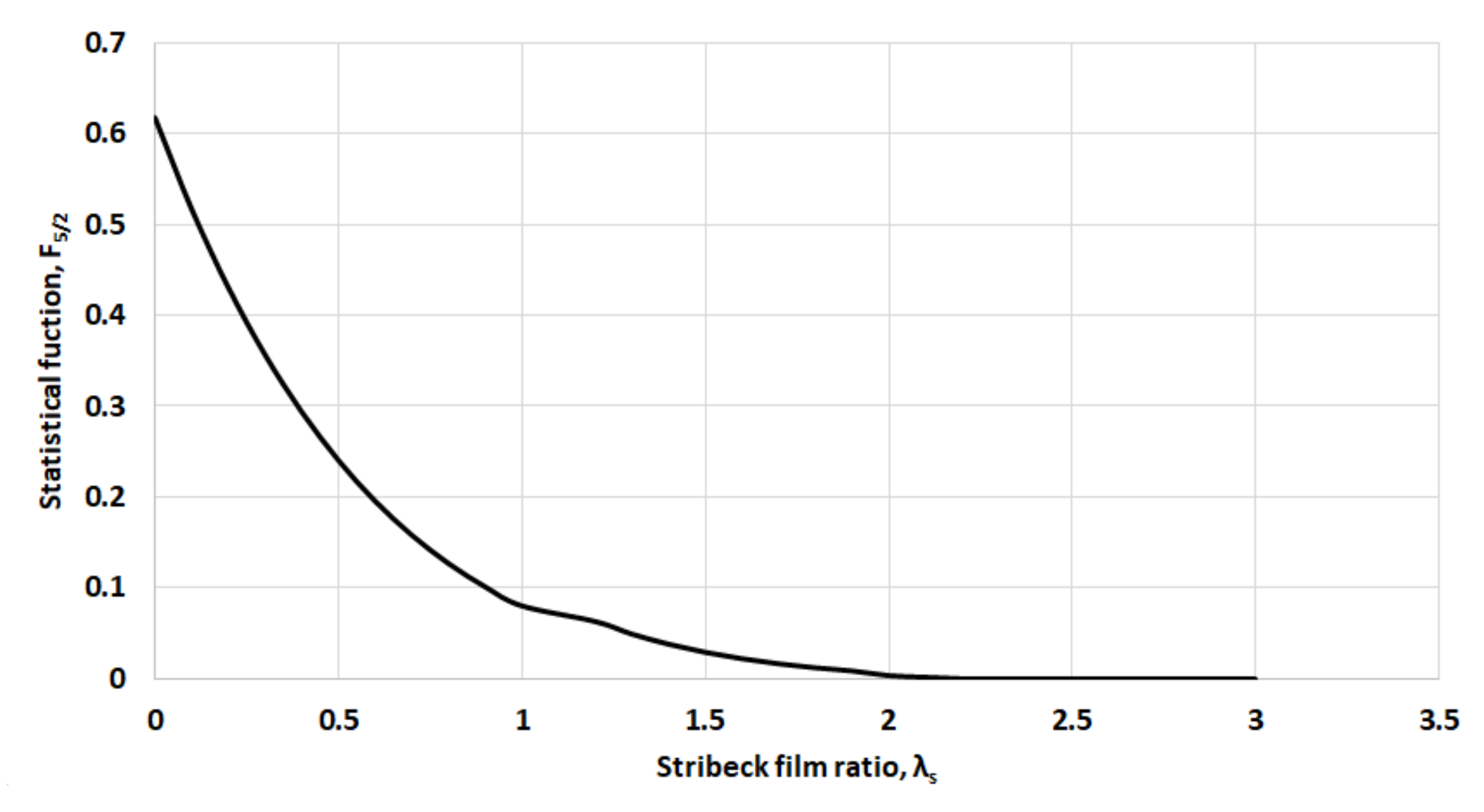
where ζ and κ are the relative parameters according to the studied coated surfaces. σ is the composite standard deviation of roughness. This data is provided later in analytical results. λs expresses the usual Stribeck lubricant film ratio. In this study, the statistical function of F5/2 can be predicted by a fifth order polynomial curve as it is referred by Teodorescu et al. [37]. Therefore, for λs ≤ λcrit = 2.22:
and for λs > λcrit = 2.22:
where λcrit is the critical film ratio. In order to improve the calculation of the asperities along the ring profile, where the lubricant film falls below the critical film ratio, it is crucial to predict the real asperities located close to the contact centre, which are represented in critical length bc of Figure 1. Consequently, the contact area A through expression (7) should be modified, and this conversion should follow the variations of F5/2. Figure 3 shows the variation of the statistical function F5/2 with the Stribeck film ratio.
This approach was suggested by Gore et al. [28], representing the load carried by the asperities in the critical length bc as follows:
in which for the symmetric parabolic ring shape, the integral term in Equation (10) becomes:
where , and .
2.4. Method of Analytical Solution
Under mixed and hydrodynamic lubrication, the total ring load Wtot is given as:
At any time of the analysis, the ring balance should be made. This is achieved if the following expression is fulfilled:
If the balance is not confirmed, then the minimum film thickness is re-calculated as follows:
In this case, the parameter ε is considered as: ε = 0.15. This value was used for solution stability and fast convergence.
2.5. Low Viscosity Oils
Accurate prediction of the ring-liner tribological behaviour is the lubricant rheology into the contact. Synthetic oils SAE 15W40 and SAE 0W20 were used in this analysis. Taylor [32] described the lubricant properties of these lubricants, particularly for advanced high-performance engines. The lubricant viscosity variation was given by Vogel equation [38]:
where k, θ1 and θ2 are the parameters of each oil, and T is the lubricant temperature. Table 2 shows the input parameters for each engine oil with the corresponding dynamic viscosities at 120 °C.
2.6. Ring Friction
Under mixed and hydrodynamic regimes of lubrication, the ring friction can be predicted from two sources: the viscous shear of lubricant film (viscous friction) and the direct contact by the asperities (boundary friction). This can be expressed as [35]:
where the viscous friction fv is:
in which, τ is the viscous shear stress caused by Couette flow of the oil film into the contact. With regard to the Poiseuille shear, this form was ignored in this analysis owing to the low-pressure gradients for thin films in the mixed conditions. Therefore, the expression of viscous friction can be modified for a symmetric parabolic profile as follows [28]:
when the minimum film thickness is limited between the ring and cylinder liner and the Stribeck film ratio becomes 1 ≤ λs < 3, the boundary friction fb can be written as [35]:
where is the non-Newtonian Eyring shear stress and is the boundary shear strength of contact asperities. Styles et al. [39] reported that surface roughness of piston ring during the wear process would affect this parameter, which can be measured using an Atomic Force Microscope (AFM). It was found that for a high-performance piston ring with Ni-Cr-Mo coating, this value can be varied between 0.35 (new profile) to 0.25 (run-in profile). In addition to this topic, Zabala et al. [27] and Tomanik et al. [33] also measured the coefficient of boundary shear strength using different engine lubricants. In this study, μasp was assumed constant (a hypothetical case) with the experimental value of 0.22 for all running cases. This value was selected by Gore et al. [28] as well as the lubricant oil SAE 10W40 reacted with a stainless steel piston ring, which has similar properties with this investigation in order to model more realistic contact conditions. For this reason, a detailed analysis for ring coated profiles combined with the low viscosity lubricants should be further investigated in the next work.
Regarding the first section of the boundary friction equation, it is important to predict the real contact of the asperities Acon for the studied symmetric parabolic ring. This can be defined as [28]:
where the integral term in Equation (20) for symmetric parabolic piston ring is:
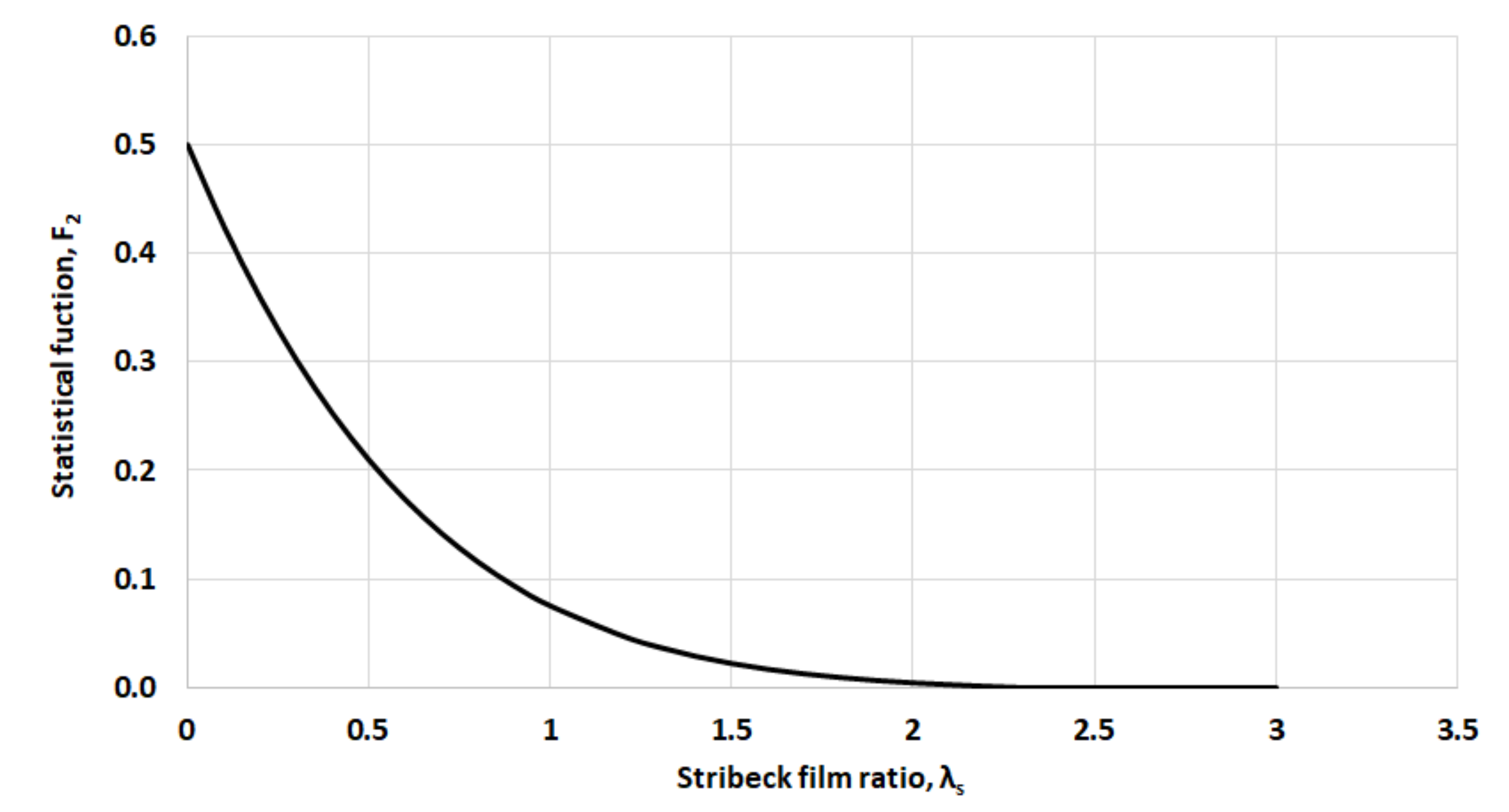
in which, , and . Furthermore, the statistical function of F2 can be also presented by a fifth order polynomial curve (Figure 4). In more details, for λs ≤ λcrit = 2.29, this function becomes [37]:
Finally, the boundary friction can be written as:
3. Results and Discussion
3.1. Input Coated Piston Rings and Cylinder Liner Data for the Analysis
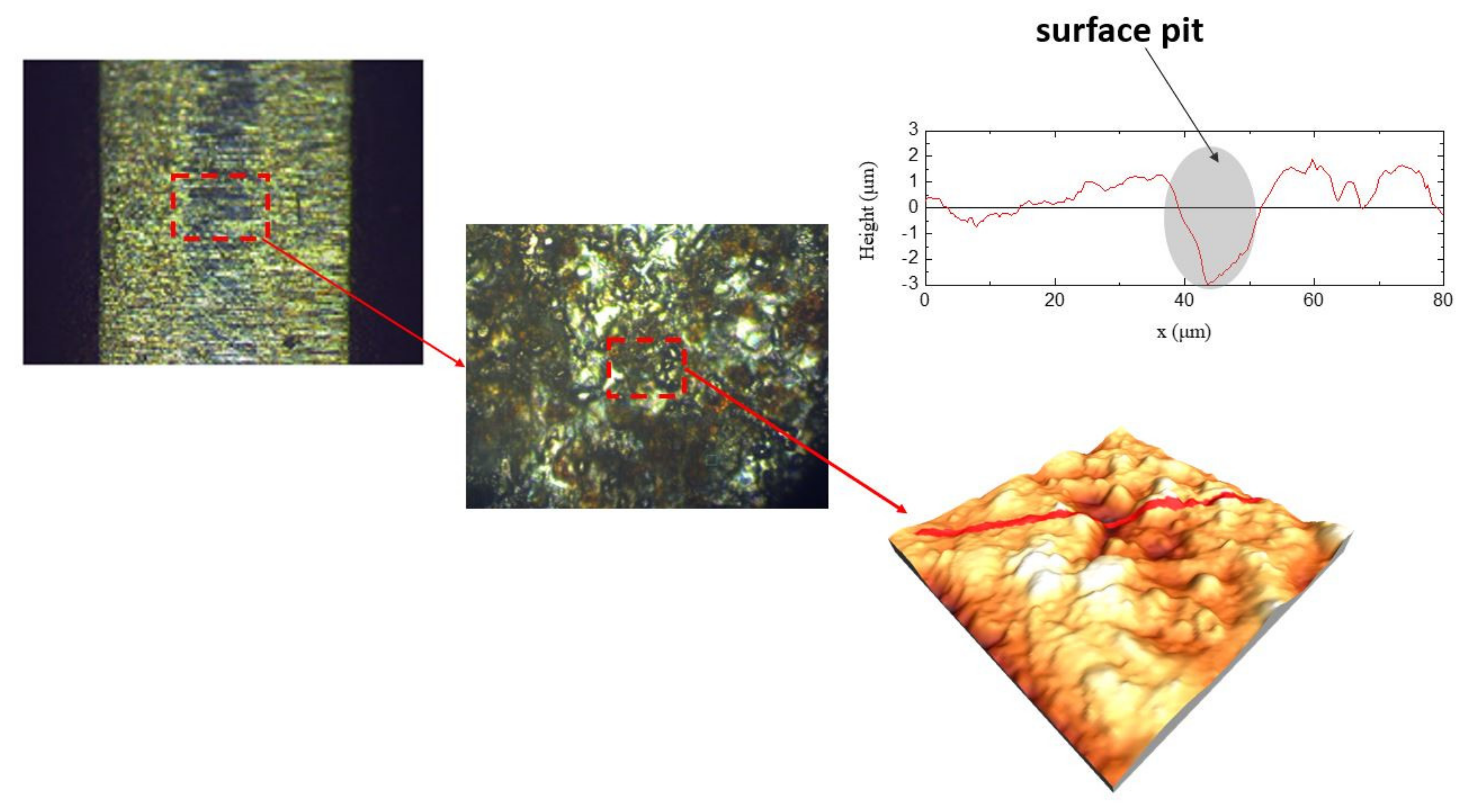
For this purpose, a thin piston ring profile was analysed, which can be used for a light vehicle. Zavos and Nikolakopoulos [34] presented the full data of four-stroke motorbike engine, which can be used for this type of piston ring. The base material of the investigated top piston ring was made by stainless steel from the manufacturer. Figure 5 shows generally the measurement process in the coated surfaces for both studied rings.
In this study, the profile of the ring was illustrated using the Leica Light Microscopy and an ambient atomic force microscope (AFM) type of MultiView2000-Nanonics Imaging. The corresponding topographical parameters were measured by a portable profilometer through the HOMMEL TESTER T500 device based on DIN 4768 and ISO 4287/1 with high resolution of 10 nm. Table 3 presents the input data for the coated piston rings and the uncoated cylinder liner. The parameters (ζκσ) and (σ/κ) are obtained using the basic theory by Arcoumanis et al. [40].
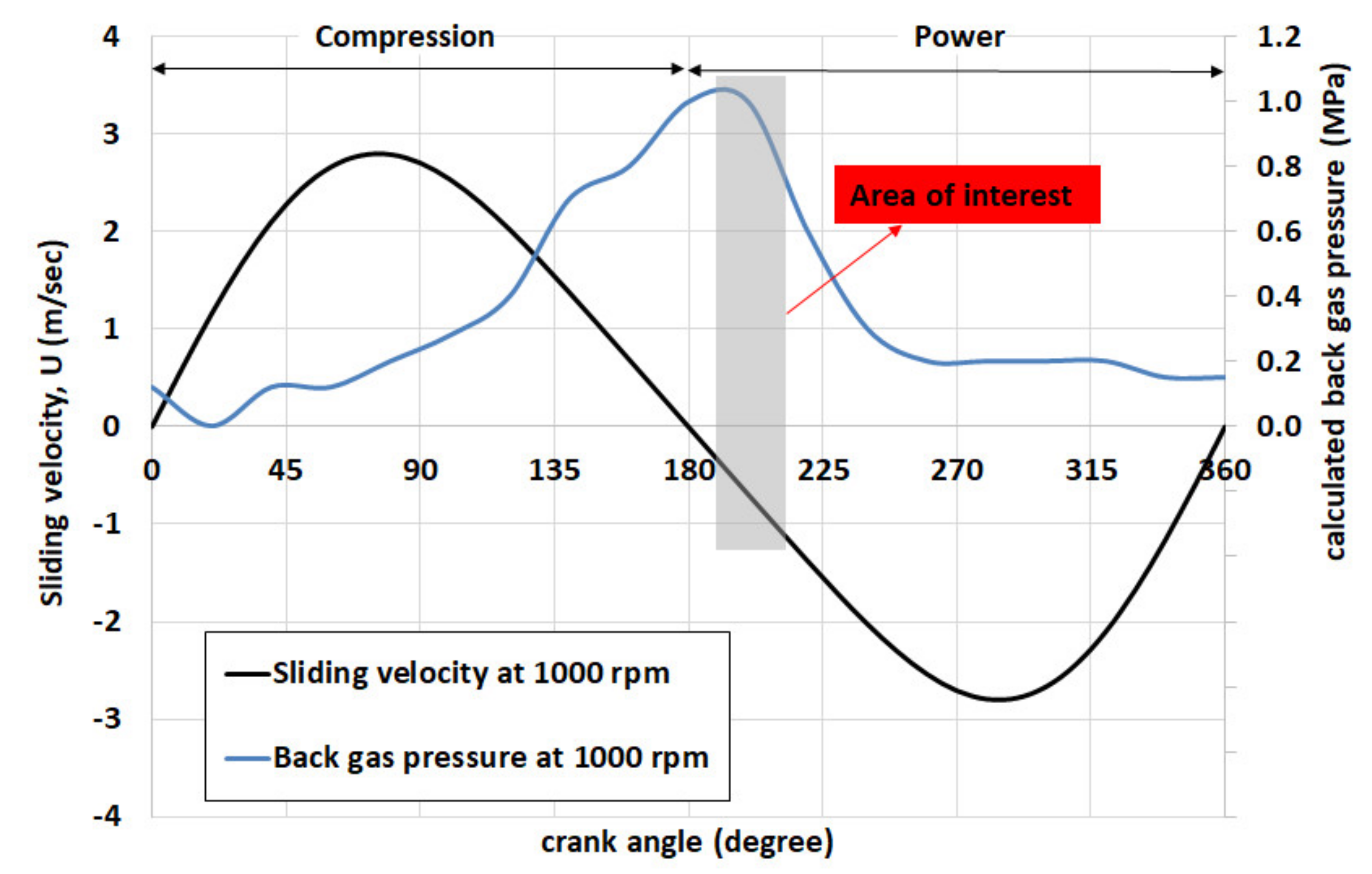
The table shows the main operating parameters of this analysis such as lubricant temperature, sliding velocity and applied load. To replicate mixed lubrication into the ring-liner conjunction at TDC region, the applied load was determined at 60 N and the sliding velocity was considered in the range of 0.5–1.16 m/s, as the ring moved during the power stroke for a small motor engine (Figure 6). The lubricant temperature of 120 °C represents the piston ring temperature in the motor engine at idle condition for 1 h. This temperature corresponds to hot conditions where the asperities interactions are predominant (mixed conditions) around the TDC position [41]. Further information for this motor engine can be also found in reference [34].
3.2. Analysis of Minimum Film Thickness and Coefficient of Friction
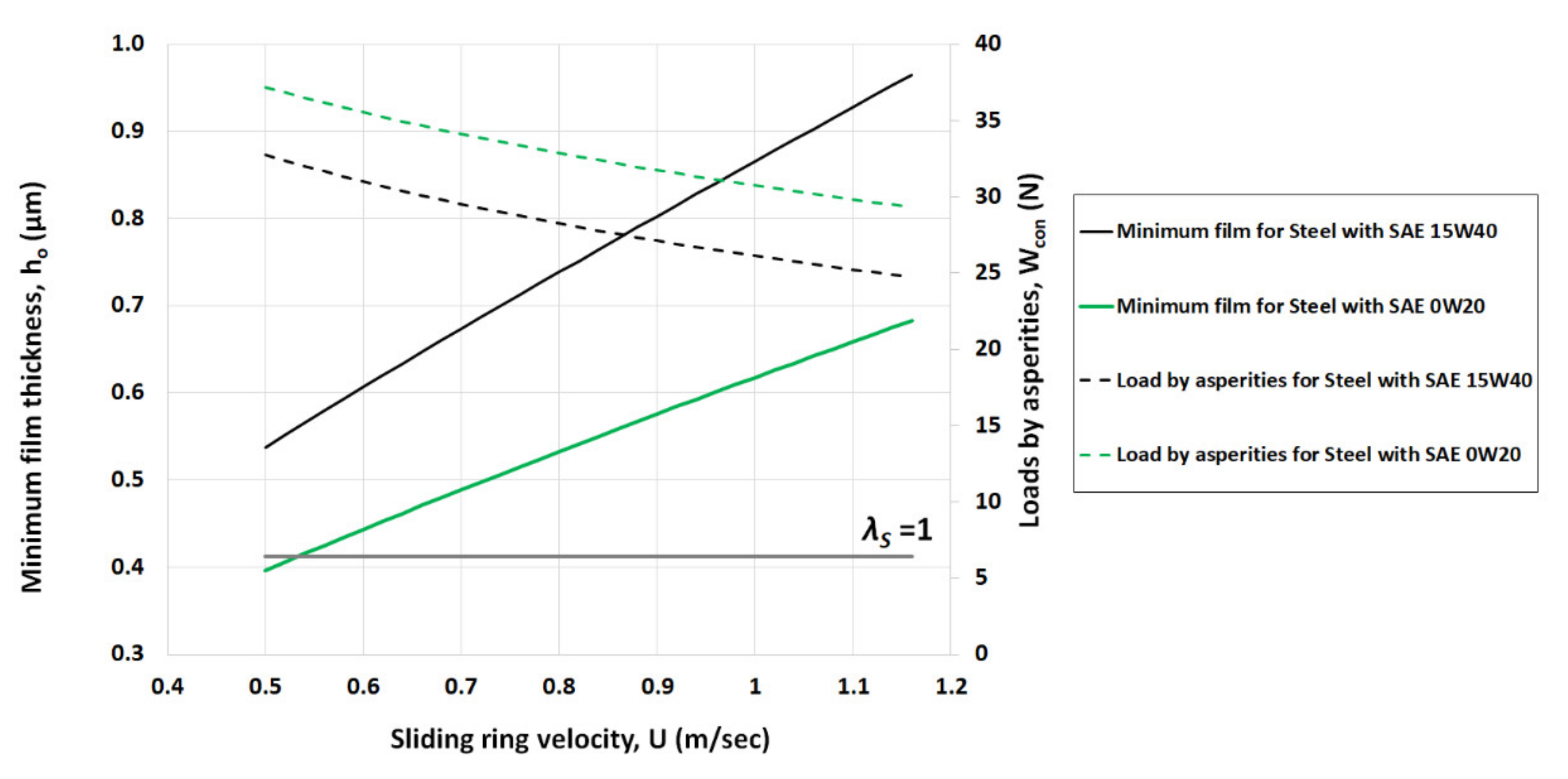
Minimum film thickness is an important factor for mechanical components where there is a lubricant film between the conjugating surfaces. This value distinguishes the basic regimes of lubrication: boundary, mixed and full hydrodynamics through Stribeck film ratio [42]. Figure 7 shows the variation of minimum film thickness and load carried by the asperities for uncoated steel ring lubricated with SAE 15W40 and SAE 0W20. Both low viscosity lubricants showed the evidence of mixed/boundary lubrication. Particularly, the minimum film was varied between 0.53 μm to 0.96 μm for SAE 15W40 and between 0.39 μm to 0.68 μm for SAE 0W20. As expected, the low viscosity synthetic oil SAE 15W40 has higher minimum films compared to the synthetic oil SAE 0W20. This difference is generally 35.8–41.1% in the minimum films. This behaviour can be explained owing to the higher lubricant viscosity of SAE 15W40 (μ = 7.3 mPas) related to the oil SAE 0W20, where its dynamic viscosity is quite lower (μ = 4.5 mPas). Furthermore, the minimum films of oil SAE 0W20 produced higher loads due to the asperities within the contact. It is obvious that the minimum film of this low viscosity lubricant is determined around the composite surface roughness of steel ring (σ ≈ 0.412 μm) for very low speed of 0.5 m/s. This would lead to possible failure consequences of piston rings such as scratches, scuffing and high oil consumption. Thus, the surface protection of piston ring and the wear resistance enhancement must be done using a coating layer [43].
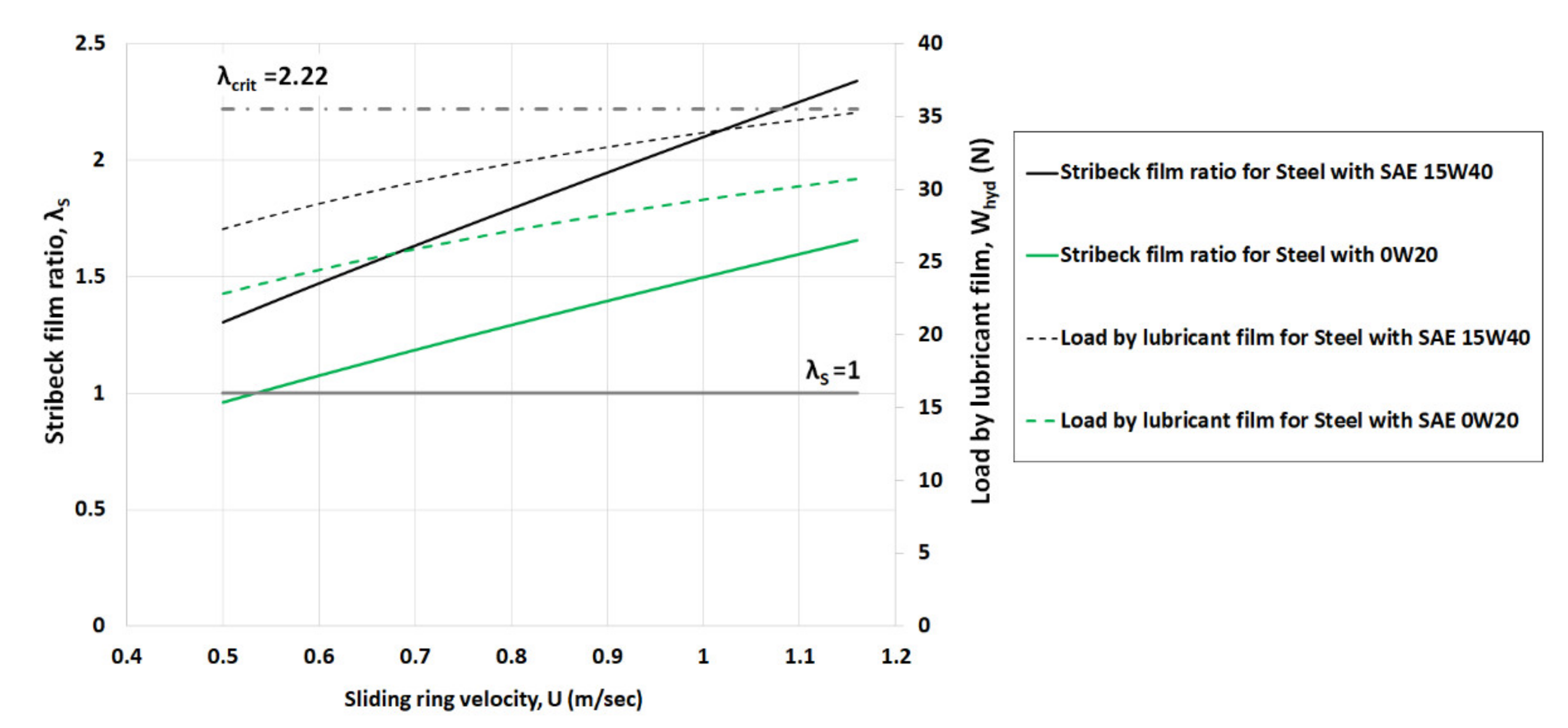
The direct comparison of Stribeck film ratio and hydrodynamic load by the lubricant film using the rough uncoated steel piston ring presented in Figure 8. As mentioned before, at low sliding velocities in the range of 0.5–1.16 m/s, the mixed conditions are prevalent for both lubricants, specifically for the lower viscosity oil SAE 0W20. As the sliding velocity is increased, the higher viscosity oil SAE 15W40 would move the ring profile away from the boundary and into the mixed/hydrodynamic lubrication. This is supported by the more rapid increase in generated hydrodynamic load for synthetic oil SAE 15W40, as well as the fluid velocity becomes higher, and the lubricant viscosity is greater. These observations indicated that low viscosity oils rheology properties have a strong effect in the amount of boundary or mixed and hydrodynamic conditions into the conjugating surfaces. For example, in the case of the velocities between 0.68 m/s and 1.16 m/s, the hydrodynamic load becomes larger compared to the load by the asperities using the highest viscosity oil SAE 15W40. Instead, for the synthetic oil SAE 0W20, the load by lubricant film grows up in relation to the load carried by the asperities for the velocities between 1.08 m/s and 1.16 m/s.
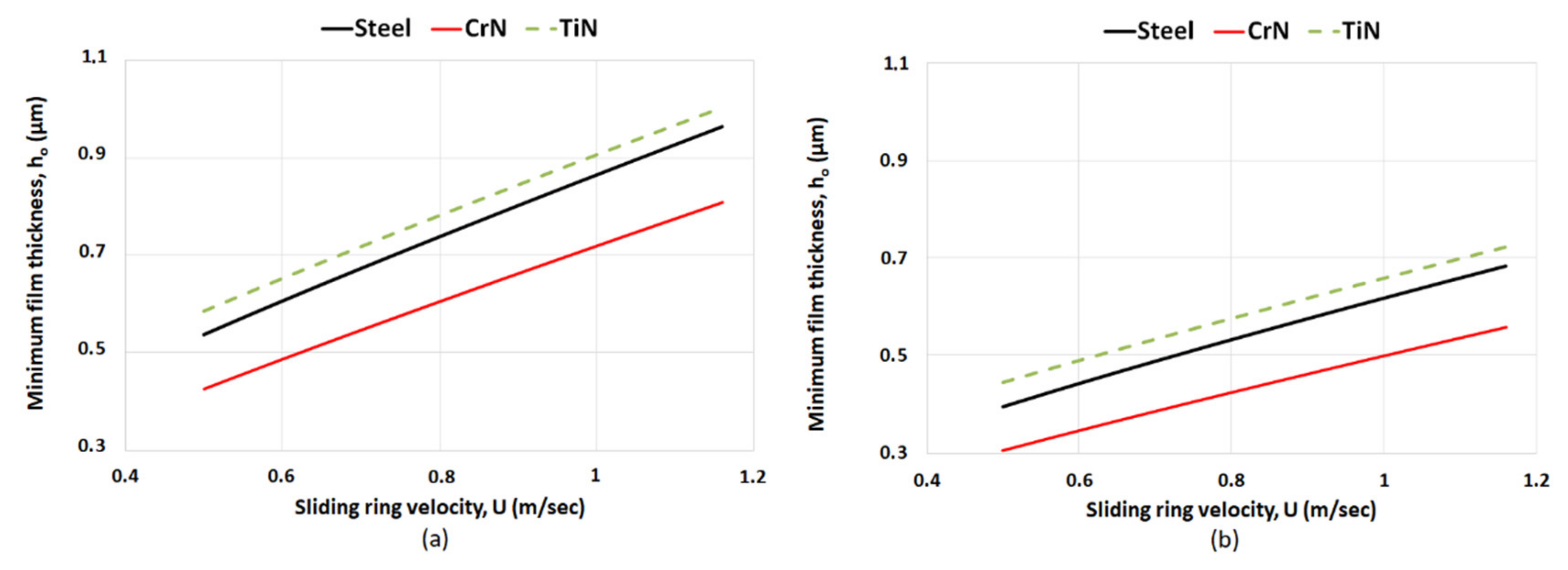
Under hot lubricant temperature of 120 °C, the variations in the predicted minimum film thickness for steel, CrN and TiN coated rings are illustrated in Figure 9. Lower minimum films are obtained for all studied coatings using the lower viscosity oil SAE 0W20. For instance, the minimum film falls from 0.42 μm (SAE 15W40) to 0.3 μm (SAE 0W20) for CrN coating at 0.5m/s. Instead, the minimum thickness also decreases from 0.58 μm (SAE 15W40) to 0.44 μm (SAE 0W20) for TiN coating.
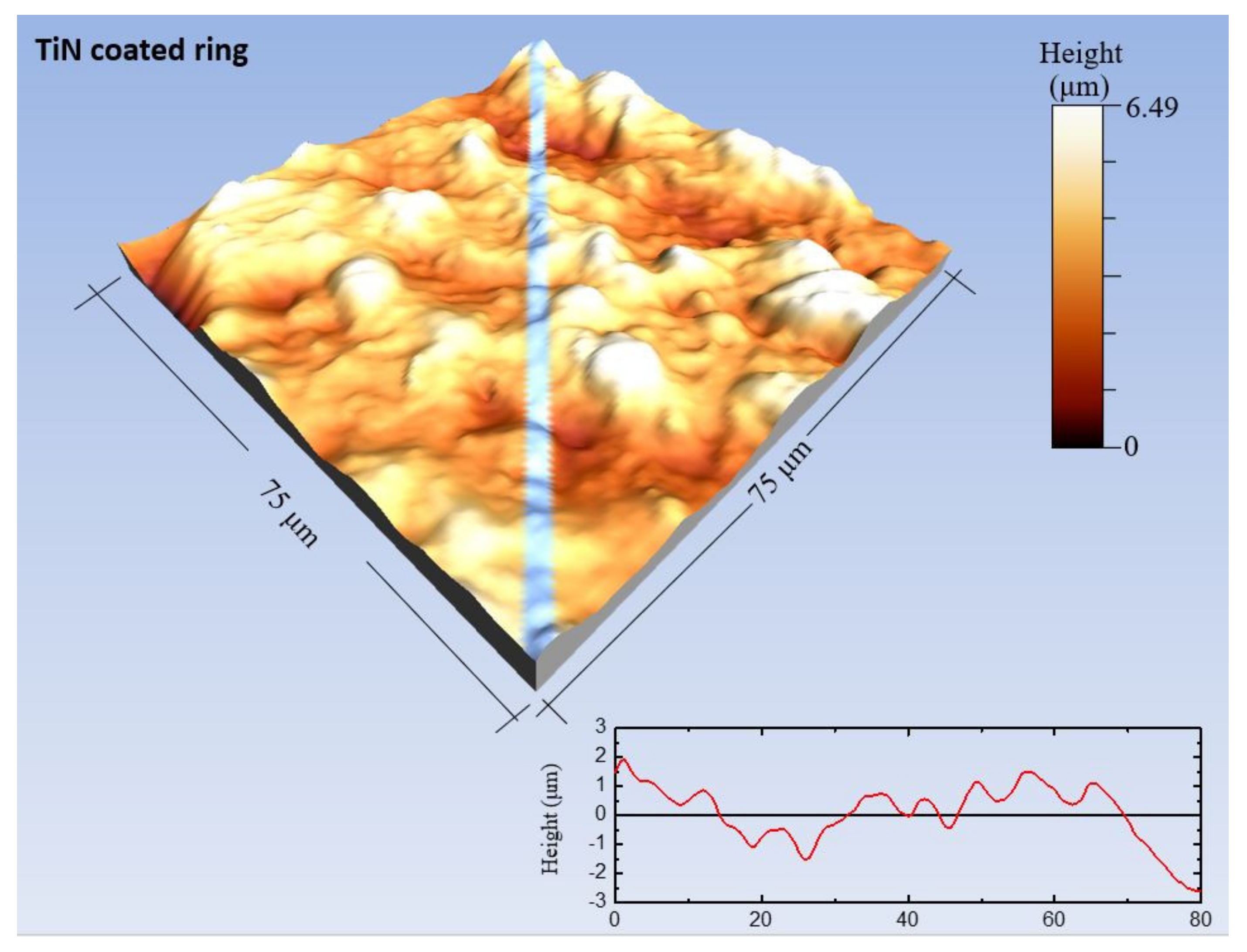
As observed, the CrN coated ring showed the minimum thicknesses because of the lower composite surface roughness of 0.26 μm. On the other hand, TiN coated ring has higher films owing to the rougher surface with sharp irregularities on the surface (Figure 10). It is important to note that the cylinder liner is uncoated with roughness of 0.1 μm. In reality, cylinder liners are also coated with hard and polished surfaces [44]. This analysis does not take into account the impact of cylinder profile in the piston ring tribological performance. This point was not within the scope of the present study.
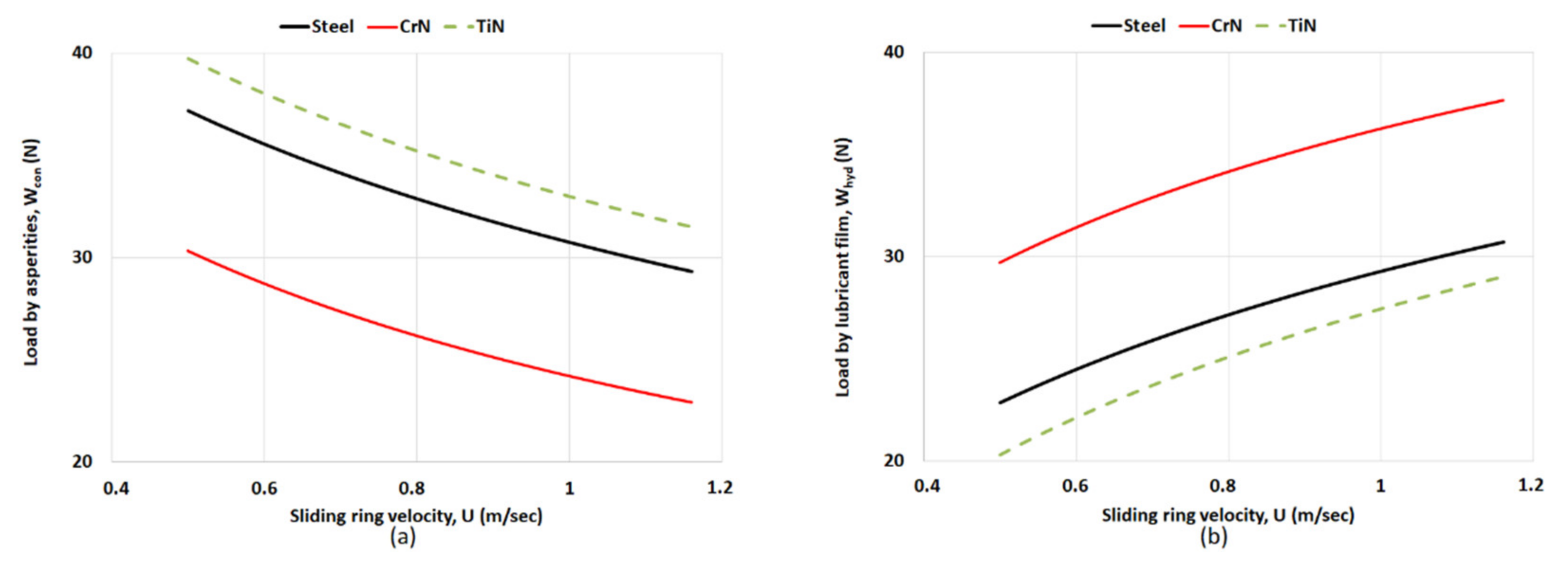
The lubrication mechanisms into the contact for the studied ring coatings are provided in detail in Figure 11. This figure shows the variation of the hydrodynamic load and the load carried by the asperities using the low viscosity oil SAE 0W20. The surface topography has shown critical impact on tribological parameters of coated piston rings. This is evident in the figure, where the smoother CrN coated ring has lower load carried by the asperities due to the minimum asperity slope and higher hydrodynamic load. Practically, the CrN coated ring showed different morphology with limited peaks but with significant proportion of pits (see Figure 5). On the other hand, the load by asperities is higher for the rougher TiN layer. Clearly, the difference between the two coated types occurs when mixed regimes of lubrication are dominant due to the roughness parameter (ζκσ) and asperity slope (σ/κ) using the analytical Equation (10). Therefore, this section investigates the contact mechanisms of the rough coated surfaces (CrN and TiN) to explain the difference in their performance.
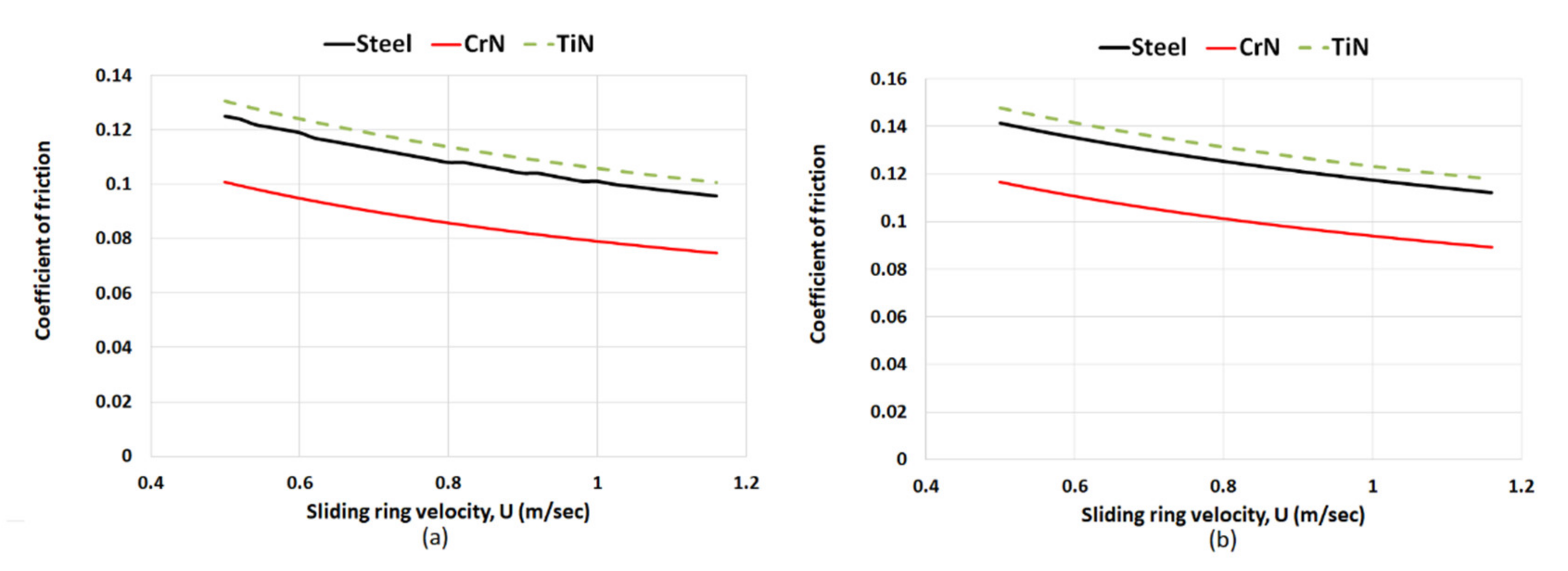
Figure 12 shows the coefficient of friction variation with increasing sliding velocity for both lubricants. The boundary and mixed conditions are obvious, where the coefficient of friction varies between 0.14–0.074 for three studied piston rings. As already mentioned before, the total load is carried by the formed thin lubricant film and the contacting asperities (see Figure 11). The effect of lower asperity interactions and higher hydrodynamic contribution showed the slighter coefficient of friction for the CrN piston ring. Particularly, the coefficient of friction was varied in the range of 0.11–0.074. On the other hand, the TiN coating led to higher values of 0.14–0.1 for both lubricants. Therefore, the role of the surface topography and formed tribofilm is very crucial owing to the transient lubricant entrainment. These predictions showed that PVD TiN has higher coefficient of friction, but the ring durability are superior compared to the uncoated steel ring. This is clear for both lubricants in the figure. However, it is also known that the tribofilm with coating characterists affects total friction through boundary shear strength of asperities, μasp. This is a significant parameter for boundary friction calculation. Thus, investigations should be made in future research compared to the experimental measurements.
4. Summary and Conclusions
The paper demonstrates the tribological performance of piston ring conjunction for different coatings using an analytical model. The operating conditions represent the contact of a thin top piston ring at TDC region in a small motor engine. Electroplated CrN and PVD TiN coatings were studied to predict the main tribological parameters such as the minimum film, the load carried by the asperities, the load by lubricant film and the coefficient of friction. The surface properties of these coatings were measured and used in the analytical model. A simple mathematical model was developed which captures boundary/mixed regime of lubrication using alternative expressions of Greenwood-Tripp approach describing the real contact area by the asperities. The results are compared and discussed for two different low viscosity oils.
The predictions of minimum film thickness showed that the boundary and mixed regimes of lubrication are prevalent at TDC reversal in piston ring conjunction. The synthetic oil SAE 0W20 provided quite lower lubricant films than synthetic oil SAE 15W40 because of lower lubricant viscosity. Particularly, CrN coated ring shows average minimum films in the range of 0.3–0.8 μm while the TiN coated ring shows average films in the range of 0.44–1 μm for both lubricants. The major finding of this work was that CrN coating has minimum films because of the lower composite surface roughness, but TiN layer has greater films owing to the rougher surface with sharp irregularities on the surface. This trend led to the slighter coefficient of friction (0.11) for CrN coating, where the mechanism of lubrication conditions enhances the hydrodynamic load and decreases the load by the asperities. This can be explained due to the morphology of surface where peaks are not sharp, and the asperity slope is lower. At the same time, the rougher coating of PVD TiN has shown the higher coefficient of friction (0.14). These predictions found the huge impact of roughness parameter and asperity slope in the calculation of load by asperities. Therefore, the coating topography should be mentioned in analytical modelling or multi-scale analysis in order to explain the differences in the tribological performance. Overall, CrN and TiN coatings are frequently used in piston rings providing good wear resistance and scuffing behaviour. However, the manufacturing process of these coatings is important to improve its topography. A new design solution, called surface textures, can be led to controlled lower friction and better durability. This was reported in detail by Howell-Smith et al. [44], and Zavos and Nikolakopoulos [45].
The tribological performance of these coated piston rings was not only affected by the surface topography but critically by the operating conditions, such as load, temperature and lubricant ageing. Consequently, further work can be performed in the next step, including extended friction and wear tests. Full scale engine tests are also needed to identify “optimum” piston rings performance. Particularly, more detailed investigations are detected in lower viscosity lubricant grades, where the optimum additives are a priority for the surface protection. This paper aims to represent a relevant tool to study the piston ring tribology and evaluate potential solutions using a time efficient method for different surface characteristics.
Funding
This research received no external funding.
Conflicts of Interest
The authors declare no conflict of interest.
Nomenclature
| A | nominal contact area |
| Acon | asperity contact area |
| b | ring face-width contact |
| bc | critical length along the ring face-width contact |
| c | ring curvature or crown height |
| Ε | Young’s modulus of elasticity |
| Ε* | equivalent Young’s modulus of elasticity |
| F | applied ring load |
| ftot | total friction |
| fv | viscous friction |
| fb | boundary friction |
| F5/2, F2 | statistical functions |
| h | lubricant film thickness |
| hc | critical film thickness |
| ho | minimum film thickness |
| hs | ring face-width profile |
| k | Vogel parameter for describing lubricant viscosity variation with temperature |
| L | ring lateral length |
| phyd | hydrodynamic pressure |
| Pinlet | inlet pressure at the piston ring conjunction |
| Pout | outlet pressure at the piston ring conjunction |
| r | radius of ring curvature |
| M,N | input variables |
| T | lubricant temperature |
| U | sliding velocity |
| Wtot | total load carrying capacity |
| Wcon | load share by the asperities |
| Whyd | load carried by the lubricant film |
| Greek symbols | |
| δ | local contact deformation |
| ε | step for minimum film thickness loop |
| ζ | surface density of asperity peaks |
| θ1,θ2 | Vogel parameters for lubricant viscosity variation with temperature |
| κ | average asperity tip radius |
| λs | Stribeck oil film parameter |
| μ | lubricant dynamic viscosity |
| μasp | coefficient of boundary shear strength |
| ν | Poisson ratio |
| σ | root mean square roughness value of the studied tribo-pair |
| τ | viscous shear stress |
| το | Eyring shear stress of the lubricant film |
| X | parameter for ring balance |
| Superscripts | |
| n | iteration step |
| Subscripts | |
| asp | asperity |
| b | boundary |
| c,crit | critical |
| con | contact |
| hyd | hydrodynamic |
| l | liner |
| r | ring |
| s | shape |
| S | Stribeck |
| tot | total |
| v | viscous |
References
- Tung, S.C.; McMillan, M.L. Automotive tribology overview of current advances and challenges for the future. Tribol. Int. 2004, 37, 517–536. [Google Scholar] [CrossRef]
- Szymanski, P.; Ciuffo, B.; Fontaras, G.; Martini, G.; Pekar, F.; Wozniak, M.; Ozuna, G.; Siczek, K.; Stoeck, T.; Sitnik, L. The future of road transport in Europe. Environmental implications of automated, connected and low-carbon mobility. Combust. Engines 2021, 186, 3–10. [Google Scholar] [CrossRef]
- Golloch, R.; Kessen, U.; Merker, G.P. Tribological investigations on the piston assembly group of a diesel engine. MTZ Worldw. 2002, 63, 21–24. [Google Scholar] [CrossRef]
- Senatore, A.; Aleksendric, D. Advances in piston rings modelling and design. Recent Pat. Eng. 2013, 7, 51–67. [Google Scholar] [CrossRef]
- Livanos, G.A.; Kyrtatos, N.P. Friction model of a marine diesel engine piston assembly. Tribol. Int. 2007, 40, 1441–1453. [Google Scholar] [CrossRef]
- Delprete, C.; Razavykia, A. Piston ring–liner lubrication and tribological performance evaluation: A review. Proc. Inst. Mech. Eng. Part J J. Eng. Tribol. 2018, 232, 193–209. [Google Scholar] [CrossRef]
- Mishra, P.C. Modeling the root causes of engine friction loss: Transient elastohydrodynamics of a piston subsystem and cylinder liner lubricated contact. Appl. Math. Model. 2015, 39, 2234–2260. [Google Scholar] [CrossRef]
- Marui, E.; Endo, H. Effect of reciprocating and unidirectional sliding motion on the friction and wear of copper on steel. Wear 2001, 249, 582–591. [Google Scholar] [CrossRef]
- Chaudhari, T.; Sutaria, B. Investigation of friction characteristics in segmented piston ring liner assembly of IC engine. Perspect. Sci. 2016, 8, 599–602. [Google Scholar] [CrossRef] [Green Version]
- Furuhama, S. A Dynamic Theory of Piston-Ring Lubrication: 1st Report, Calculation. Bull. JSME 1959, 2, 423–428. [Google Scholar] [CrossRef]
- Furuhama, S. A Dynamic Theory of Piston-Ring Lubrication: 2nd Report, Experiment. Bull. JSME 1960, 3, 291–297. [Google Scholar] [CrossRef] [Green Version]
- Tian, T.; Noordzij, L.; Wong, V.W.; Heywood, J.B. Modeling Piston-Ring Dynamics, Blowby, and Ring-Twist Effects. ASME J. Eng. Gas Turbines Power 1998, 120, 843–854. [Google Scholar] [CrossRef]
- Patir, N.; Cheng, H.S. Application of average flow model to lubrication between rough sliding surfaces. Trans. ASME 1979, 101, 220–229. [Google Scholar] [CrossRef]
- Wolff, A. Influence of piston ring pack configuration on blowby and friction losses in a marine two-stroke engine. Combust. Engines 2017, 170, 164–170. [Google Scholar] [CrossRef]
- Priest, M.; Dowson, D.; Taylor, C.M. Theoretical modelling of cavitation in piston ring lubrication. Proc. Inst. Mech. Eng. Part C J. Mech. Eng. Sci. 2000, 214, 435–447. [Google Scholar] [CrossRef]
- Chong, W.W.F.; Howell-Smith, S.; Teodorescu, M.; Vaughan, N.D. The influence of inter-ring pressures on piston-ring/liner tribological conjunction. Proc. Inst. Mech. Eng. Part J J. Eng. Tribol. 2013, 227, 154–167. [Google Scholar] [CrossRef]
- Nouri, J.M.; Vasilakos, I.; Yan, Y.; Reyes-Aldasoro, C.C. Effect of viscosity and speed on oil cavitation development in a single piston-ring lubricant assembly. Lubricants 2019, 7, 88. [Google Scholar] [CrossRef] [Green Version]
- Taylor, R.I.; Morgan, N.; Mainwaring, R.; Davenport, T. How much mixed/boundary friction is there in an engine—And where is it? Proc. Inst. Mech. Eng. Part J J. Eng. Tribol. 2020, 234, 1563–1579. [Google Scholar] [CrossRef]
- Morris, N.; Rahmani, R.; Rahnejat, H.; King, P.D.; Fitzsimons, B. The influence of piston ring geometry and topography on friction. Proc. Inst. Mech. Eng. Part J J. Eng. Tribol. 2013, 227, 141–153. [Google Scholar] [CrossRef] [Green Version]
- Söderfjäll, M.; Herbst, H.M.; Larsson, R.; Almqvist, A. Influence on friction from piston ring design, cylinder liner roughness and lubricant properties. Tribol. Int. 2017, 116, 272–284. [Google Scholar] [CrossRef]
- Erdemir, A.; Holmberg, K. Energy consumption due to friction in motored vehicles and low-friction coatings to reduce it. In Coating Technology for Vehicle Applications; Springer: Cham, Switzerland, 2015; pp. 1–23. [Google Scholar]
- Ferreira, R.; Martins, J.; Carvalho, Ó.; Sobral, L.; Carvalho, S.; Silva, F. Tribological solutions for engine piston ring surfaces: An overview on the materials and manufacturing. Mater. Manuf. Process. 2020, 35, 498–520. [Google Scholar] [CrossRef]
- Friedrich, C.; Berg, G.; Broszeit, E.; Rick, F.; Holland, J. PVD CrxN coatings for tribological application on piston rings. Surf Coat. Technol. 1997, 97, 661–668. [Google Scholar] [CrossRef]
- Abril, S.O.; García, C.P.; León, J.P. Numerical and Experimental Analysis of the Potential Fuel Savings and Reduction in CO Emissions by Implementing Cylinder Bore Coating Materials Applied to Diesel Engines. Lubricants 2021, 9, 19. [Google Scholar] [CrossRef]
- Barbezat, G. Advanced thermal spray technology and coating for lightweight engine blocks for the automotive industry. Surf. Coat. Technol. 2005, 200, 1990–1993. [Google Scholar] [CrossRef]
- Igartua, A.; Fdez-Pérez, X.; Conte, M.; Illarramendi, I. Tribological tests to simulate wear on piston rings. In Critical Component Wear in Heavy Duty Engines; Lakshminarayanan, P.A., Nayak, N.S., Eds.; John Wiley & Sons Ltd.: Singapore, 2011; pp. 167–195. [Google Scholar]
- Zabala, B.; Igartua, A.; Fernández, X.; Priestner, C.; Ofner, H.; Knaus, O.; Abramczuk, M.; Tribotte, P.; Girot, F.; Roman, E.; et al. Friction and wear of a piston ring/cylinder liner at the top dead centre: Experimental study and modelling. Tribol. Int. 2017, 106, 23–33. [Google Scholar] [CrossRef]
- Gore, M.; Morris, N.; Rahmani, R.; Rahnejat, H.; King, P.D.; Howell-Smith, S. A combined analytical-experimental investigation of friction in cylinder liner inserts under mixed and boundary regimes of lubrication. Lubr. Sci. 2017, 29, 293–316. [Google Scholar] [CrossRef] [Green Version]
- Dolatabadi, N.; Forder, M.; Morris, N.; Rahmani, R.; Rahnejat, H.; Howell-Smith, S. Influence of advanced cylinder coatings on vehicular fuel economy and emissions in piston compression ring conjunction. Appl. Energy 2020, 259, 114129. [Google Scholar] [CrossRef]
- Zavos, A.; Nikolakopoulos, P. Thermo-mixed lubrication analysis of coated compression rings with worn cylinder profiles. Ind. Lubr. Tribol. 2017, 69, 15–29. [Google Scholar] [CrossRef]
- Nikolakopoulos, P.G.; Grigoriadis, K.; Zavos, A. Contact modeling with a finite element model in piston ring—liner conjunction under dry conditions. Int. J. Struct. Integr. 2019, 10, 393–414. [Google Scholar] [CrossRef]
- Taylor, R.I. Squeeze film lubrication in piston rings and reciprocating contacts. Proc. Inst. Mech. Eng. Part J J. Eng. Tribol. 2015, 229, 977–988. [Google Scholar] [CrossRef]
- Tomanik, E.; Profito, F.; Sheets, B.; Souza, R. Combined lubricant–surface system approach for potential passenger car CO2 reduction on piston-ring-cylinder bore assembly. Tribol. Int. 2018, 149, 105514. [Google Scholar] [CrossRef]
- Zavos, A.; Nikolakopoulos, P.G. Tribology of new thin compression ring of fired engine under controlled conditions-a combined experimental and numerical study. Tribol. Int. 2018, 128, 214–230. [Google Scholar] [CrossRef]
- Gohar, R.; Rahnejat, H. Fundamentals of Tribology; Imperial College Press: London, UK, 2008; ISBN 978-1-84816860-2. [Google Scholar]
- Greenwood, J.A.; Tripp, J.H. The contact of two nominally flat rough surfaces. Proc. Inst. Mech. Eng. 1970, 185, 625–633. [Google Scholar] [CrossRef]
- Teodorescu, M.; Balakrishnan, S.; Rahnejat, H. Integrated tribological analysis within a multi-physics approach to system dynamics. In Tribology and Interface Engineering Series; Elsevier: Amsterdam, The Netherlands, 2005; Volume 48, pp. 725–737. [Google Scholar]
- Vogel, H. The law of the relation between the viscosity of liquids and the temperature. Phys. Z 1921, 22, 645–646. [Google Scholar]
- Styles, G.; Rahmani, R.; Rahnejat, H.; Fitzsimons, B. In-cycle and life-time friction transience in piston ring–liner conjunction under mixed regime of lubrication. Int. J. Engine Res. 2014, 15, 862–876. [Google Scholar] [CrossRef] [Green Version]
- Arcoumanis, C.; Ostovar, P.; Mortimer, R. Mixed Lubrication Modelling of Newtonian and Shear Thinning Liquids in a Piston-Ring Configuration. SAE Transactions Pap. No. 972924. 1997, 106, 1306–1331. [Google Scholar]
- Rahmani, R.; Rahnejat, H.; Fitzsimons, B.; Dowson, D. The effect of cylinder bore operating temperature on frictional loss and engine emissions in piston ring conjunction. Appl. Energy 2017, 191, 568–581. [Google Scholar] [CrossRef] [Green Version]
- Dowson, D. A central film thickness formula for elasto-hydrodynamic line contacts. In Proceedings of the 5th Leeds-Lyon Symposium, Leeds, UK, 19–22 September 1978. [Google Scholar]
- Tung, S.C.; Gao, H. Tribological Investigation of Piston Ring Coatings Operating in an Alternative Fuel and Engine Oil Blend. Tribol. Trans. 2002, 45, 381–389. [Google Scholar] [CrossRef]
- Howell-Smith, S.; Rahnejat, H.; King, P.D.; Dowson, D. Reducing in-cylinder parasitic losses through surface modification and coating. Proc. Inst. Mech. Eng. Part D J. Automob. Eng. 2014, 228, 391–402. [Google Scholar] [CrossRef] [Green Version]
- Zavos, A.; Nikolakopoulos, P.G. The effect of square-shaped pockets position in sliding line contacts under mixed regime of lubrication. Proc. Inst. Mech. Eng. Part J J. Eng. Tribol. 2019, 233, 490–506. [Google Scholar] [CrossRef]
Figure 1.
(a) Overview of 3D piston ring-liner contact, (b) piston ring (black line), lubricant film (dotted green line) and cylinder liner (blue line) with main geometrical parameters.
Figure 1.
(a) Overview of 3D piston ring-liner contact, (b) piston ring (black line), lubricant film (dotted green line) and cylinder liner (blue line) with main geometrical parameters.

Figure 2.
Inlet flow conditions and pressure distribution with Reynolds exit boundary conditions.

Figure 3.
Statistical function F5/2 vs. Stribeck film ratio λs.

Figure 4.
Statistical function F2 vs. Stribeck film ratio λs.

Figure 5.
Measurement process of the coated ring surfaces (in this case the electroplated CrN piston ring is presented).
Figure 5.
Measurement process of the coated ring surfaces (in this case the electroplated CrN piston ring is presented).

Figure 6.
Description of area of interest including calculated back gas pressure and sliding velocity for a thin piston ring of small motor engine.
Figure 6.
Description of area of interest including calculated back gas pressure and sliding velocity for a thin piston ring of small motor engine.

Figure 7.
Comparison of minimum film thickness and load by asperities for steel ring lubricated with SAE 15W40 and 0W20 at 120 °C.
Figure 7.
Comparison of minimum film thickness and load by asperities for steel ring lubricated with SAE 15W40 and 0W20 at 120 °C.

Figure 8.
Comparison of Stribeck film ratio and load by lubricant film for steel ring lubricated with SAE 15W40 and 0W20 at 120 °C.
Figure 8.
Comparison of Stribeck film ratio and load by lubricant film for steel ring lubricated with SAE 15W40 and 0W20 at 120 °C.

Figure 9.
Minimum film thickness variation with sliding velocity for (a) SAE 15W40 and (b) SAE 0W20.
Figure 9.
Minimum film thickness variation with sliding velocity for (a) SAE 15W40 and (b) SAE 0W20.

Figure 10.
3D topographic image of the TiN coated ring.

Figure 11.
(a) Variation of load by asperities and (b) variation of load by lubricant film with sliding velocity for SAE 0W20.
Figure 11.
(a) Variation of load by asperities and (b) variation of load by lubricant film with sliding velocity for SAE 0W20.

Figure 12.
Coefficient of friction variation for (a) SAE 15W40 and (b) SAE 0W20.


Table 1.
Mechanical properties of the piston ring: base material and reference coatings.
| Parameter | Cylinder Liner Base Material | Piston Ring Base Material | Ring Coatings | Unit | |
|---|---|---|---|---|---|
| Material | Aluminium | Steel | CrN | TiN | - |
| Young’s modulus of elasticity | 70 | 200 | 400 | 250 | GPa |
| Poisson’s ratio | 0.33 | 0.31 | 0.2 | 0.25 | - |
| Density | 2980 | 7850 | 5900 | 5200 | Kg m−3 |
Table 2.
Input parameters of Vogel equation and the dynamic viscosities at temperature of 120 °C.
| SAE 15W40 | SAE 0W20 | |
|---|---|---|
| K (MPA.S) | 0.029 | 0.071 |
| θ1 (°C) | 1424.3 | 983.2 |
| θ2 (°C) | 137.2 | 116.2 |
| M (120 °C) (PA.S) | 0.0073 | 0.0045 |
Table 3.
Input data for the analysis.
| Parameter | Piston Ring Uncoated | Piston Ring Coated | Unit | |
|---|---|---|---|---|
| Material | Steel | CrN | TiN | - |
| Ring-face width | 0.5 | 0.5 | 0.5 | mm |
| Ring radius of curvature | 40.5 | 40.5 | 40.5 | mm |
| Ring lateral length | 40 | 40 | 40 | mm |
| Ring surface roughness | 0.40 | 0.25 | 0.31 | μm |
| Liner surface roughness | 0.1 | 0.1 | 0.1 | μm |
| (RMS) surface finish of contact surfaces | 0.412 | 0.269 | 0.325 | μm |
| Equivalent Young’s modulus of elasticity | 115.94 | 132.18 | 121.35 | GPa |
| Roughness parameter | 0.0412 | 0.0486 | 0.0220 | - |
| Asperity slope | 2.51 × 10⁻⁵ | 1.16 × 10⁻⁵ | 5.50 × 10⁻⁴ | - |
| Eyring shear stress | 2 | 2 | 2 | MPa |
| Coefficient of boundary shear strength | 0.22 | 0.22 | 0.22 | - |
| Lubricant temperature | 120 | 120 | 120 | °C |
| Sliding velocity | 0.5–1.16 | 0.5–1.16 | 0.5–1.16 | m/s |
| Applied load | 60 | 60 | 60 | N |
Publisher’s Note: MDPI stays neutral with regard to jurisdictional claims in published maps and institutional affiliations. |
© 2021 by the author. Licensee MDPI, Basel, Switzerland. This article is an open access article distributed under the terms and conditions of the Creative Commons Attribution (CC BY) license (https://creativecommons.org/licenses/by/4.0/).
Share and Cite
MDPI and ACS Style
Zavos, A. Effect of Coating and Low Viscosity Oils on Piston Ring Friction under Mixed Regime of Lubrication through Analytical Modelling. Lubricants 2021, 9, 124. https://0-doi-org.brum.beds.ac.uk/10.3390/lubricants9120124
AMA Style
Zavos A. Effect of Coating and Low Viscosity Oils on Piston Ring Friction under Mixed Regime of Lubrication through Analytical Modelling. Lubricants. 2021; 9(12):124. https://0-doi-org.brum.beds.ac.uk/10.3390/lubricants9120124
Chicago/Turabian StyleZavos, Anastasios. 2021. "Effect of Coating and Low Viscosity Oils on Piston Ring Friction under Mixed Regime of Lubrication through Analytical Modelling" Lubricants 9, no. 12: 124. https://0-doi-org.brum.beds.ac.uk/10.3390/lubricants9120124
Note that from the first issue of 2016, this journal uses article numbers instead of page numbers. See further details here.