Iron Carbide@Carbon Nanocomposites: A Tool Box of Functional Materials
by
 , and
, and
Chiara Defilippi
1 ,
,
Mariam Omar Ali Mukadam
1,
Sabina Alexandra Nicolae
2,
Martin Richard Lees
3 and
Cristina Giordano
1,* 1
School of Biological and Chemical Sciences, Chemistry Department, Queen Mary University of London, Mile End Road, London E1 4NS, UK
2
School of Engineering and Materials Science, Queen Mary University of London, Mile End Road, London E1 4NS, UK
3
Department of Physics, University of Warwick, Coventry CV4 7AL, UK
*
Author to whom correspondence should be addressed.
Materials 2019, 12(2), 323; https://0-doi-org.brum.beds.ac.uk/10.3390/ma12020323
Submission received: 23 November 2018
/
Revised: 4 January 2019
/
Accepted: 8 January 2019
/
Published: 21 January 2019
(This article belongs to the Special Issue Novel Metal Carbide/Carbonitride Materials)
Abstract
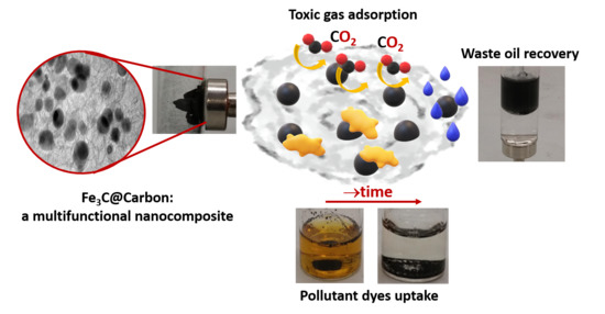
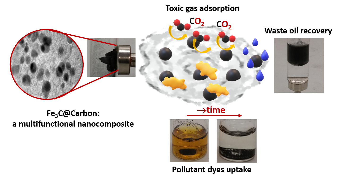
:Iron carbide (Fe3C) is a ceramic magnetic material with high potential for applications in different fields, including catalysis, medicine imaging, coatings, and sensors. Despite its interesting properties, it is still somehow largely unexplored, probably due to challenging synthetic conditions. In this contribution, we present a sol-gel-based method that allows preparing different Fe3C@C nanocomposites with tailored properties for specific applications, in particular, we have focused on and discussed potential uses for adsorption of noxious gas and waste removal. Nanocomposites were prepared using readily available and “green” sources, such as urea, simple and complex sugars, and chitosan. The nanocomposite prepared from chitosan was found to be more efficient for CO2 uptake, while the sample synthetized from cellulose had optimal capability for dye absorption and waste oil removal from water.
1. Introduction
The powerful combination of iron and carbon to improve material performances has been known since antiquity. According to a legend, the art of the carburization of iron might have been developed by an Anatolian population called Chalybes, who could have also forged the famous sword of Julius Cesar. Mythology aside, it was discovered that metallurgy employing combinations of iron and carbon dates back even to prehistory when meteorites were used as the first sources of iron [1]. Beads found in tomb 67 at Gerzeh, which were made by using meteoritic iron as the metal source, represent one of the earliest examples of exploitation of iron in Egypt [2]. Even the superior hardness of Damascus sabre seems to arise from iron carbide nanoparticles reinforcing iron metal [3].
Nowadays, the best and most known representative of the iron/carbon winning combination is surely steel but, with the advent of nanoscience, the iron/carbon blend can be finely adjusted toward designed applications. In this way, besides a mere control of the elements ratio (as for the case of steel), we can prepare iron-based (nano)composites, as this study will also show, where carbon acts as functional matrix (contributing to a higher surface area, improved electron transport, and additional conductivity to the final system), while the iron-based phases represent the (nano)fillers, providing the final material with magnetic properties. Here, a whole tool box of possibility unfolds, where final composition, size, and morphology can be tailored for specific applications. The range of applications can be even broadened if, alongside pure iron, iron carbide is also considered. Iron carbide has high thermal and chemical resistance, and might also be used for applications where harsh conditions are required and where, usually, pure iron or iron oxides do not survive. Furthermore, in its most simple cementite form, it is less toxic than pure iron but, at the same time, more magnetic than iron oxide, and can, for instance, also be considered in nanomedicine, for example, as contrast agent for MRI and drug delivery [4]. For this reason, toxicity/biocompatibility was studied both in vitro and in vivo with cytotoxicity essays, involving several cells, such as macrophage, mouse fibroblast, human breast adenocarcinoma, and human ovarian carcinoma. These tests were performed on different iron carbides, such as Fe7C3, Fe5C2, and Fe3C, and did not show significant negative side effects [4,5]. Their magnetic properties make iron-based materials also easily recoverable after use, simply by applying an external magnetic field, thus favouring their reuse and waste collection [6].
Besides biomedical applications, iron carbide can be used as sensors, coatings [7], and catalysts in processes such as Fischer–Tropsch, ammonia decomposition [8,9], and CO2 hydrogenation [10].
Considering the crucial problems of environmental pollution from air and wastewater [11,12], chemical sensing and pollutant absorbent are surely important for the detection of noxious gases, such as CO2 [11]. Iron-based materials, such as iron oxides [12,13,14] are used as magnetic gas sensors in different applications [15].
Suitable functionalization of iron carbide nanoparticles can also be used for the preparation of novel magnetic fluids.
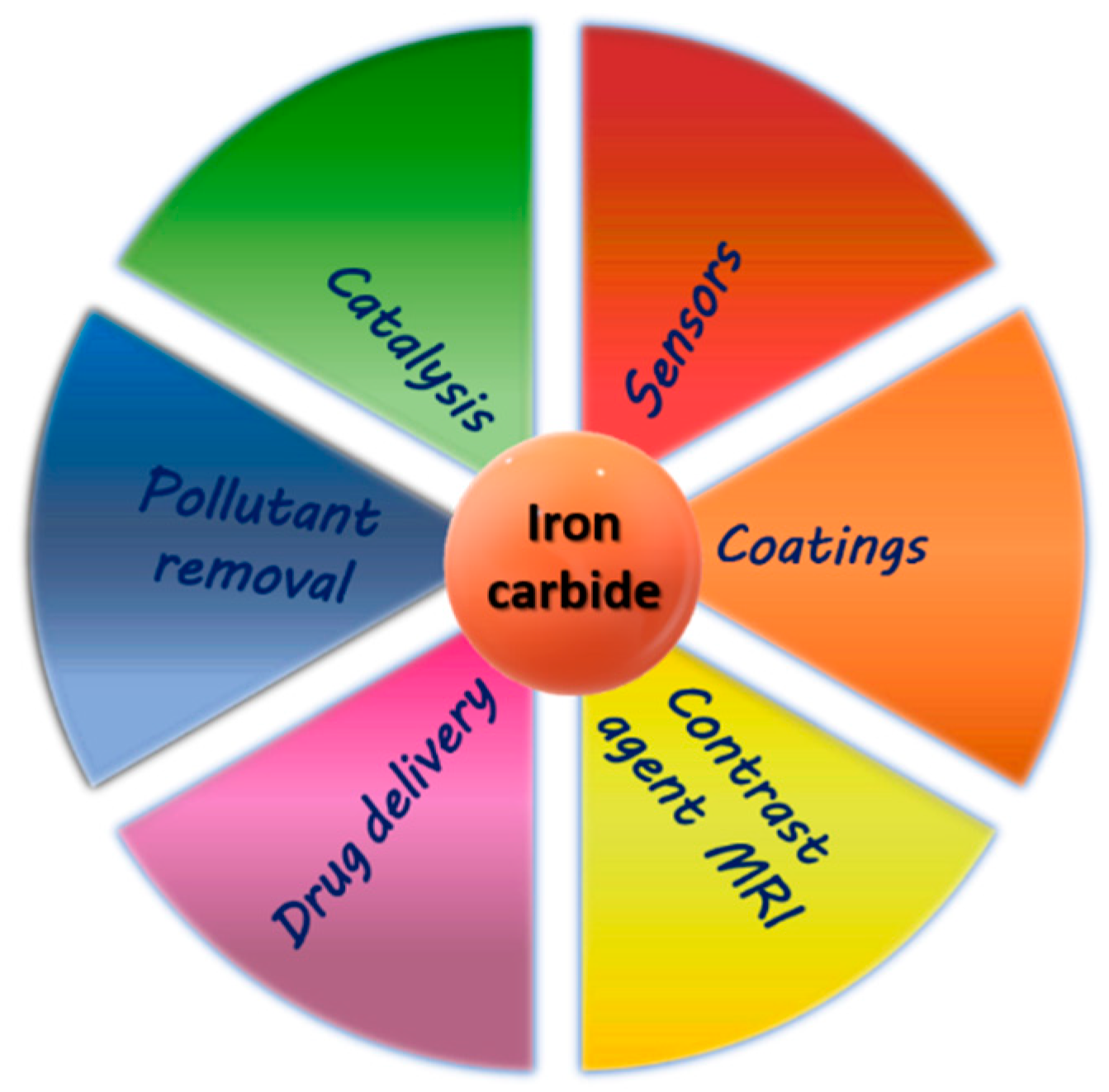
An overall representation of iron carbide applications is reported in Scheme 1.
Despite its high potential, iron carbide-based materials are still not as broadly considered as the corresponding oxides or parental metal [16]. This is probably due to the difficulties related to their synthesis, such as chemical vapour deposition (CVD)-assisted pyrolysis [7], and ammonolysis, which require high temperatures, rendering iron carbide production more expensive but also hindering control over the size and morphology of the final product when prepared at the nanoscale [17,18].
In this paper, we present how iron carbide@carbon nanocomposites can be prepared and shaped to change the final material functionality, adjusting its composition (e.g., incorporating a useful amount of iron), size, and crystallinity, but also changing properties such as magnetism, surface area, absorption, and more, which in turn result in a material with higher potential for biomedical applications (e.g., in hyperthermia treatment), diagnostic (e.g., as a contrast agent in MRI), absorption of toxic molecules, sensor technology, catalytic efficiency, etc. Here, we will only show a few model examples, but the application range can be much broader. In particular, we have focused our attention in preparing materials with higher magnetization and/or larger surface area for future potential application in the detection of noxious gases, such as CO2, or absorption of pollutants such as inorganic dyes or scrap oils from water, keeping in mind that an effective gas sensor/adsorbent should be cost-effective and highly sensitive, to detect low concentrations. Here, nanocomposites with higher surface area promote contact surfaces to the analytes, and have increased sensitivity and gas adsorption compared to bulk samples [11,19].
To overcome the synthetic difficulties, we have employed a sustainable route, based on a sol-gel process, to prepare the nanocomposite, that allows using lower reaction temperatures compared to classical synthesis, and to adjust morphology, particle dimension, and surface area of the final material simply by varying the carbon source and reaction conditions [18].
2. Materials and Methods
2.1. Iron Carbide Synthesis
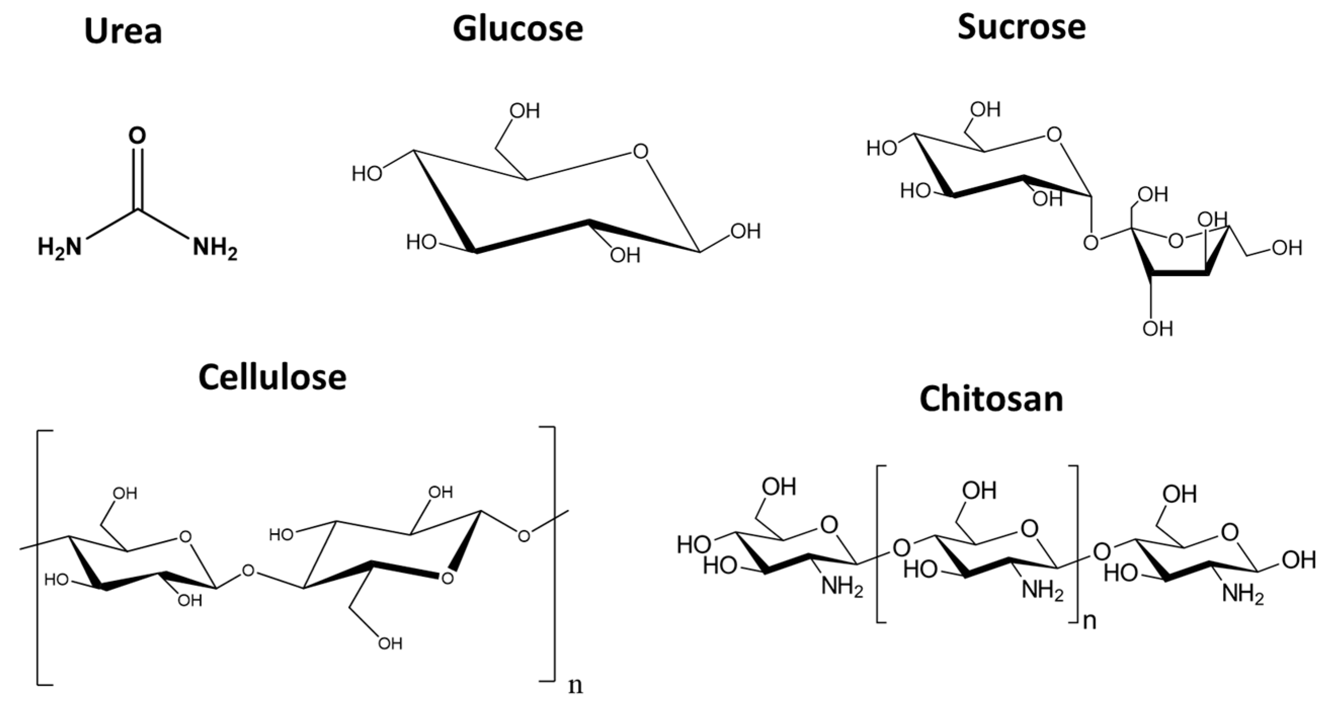
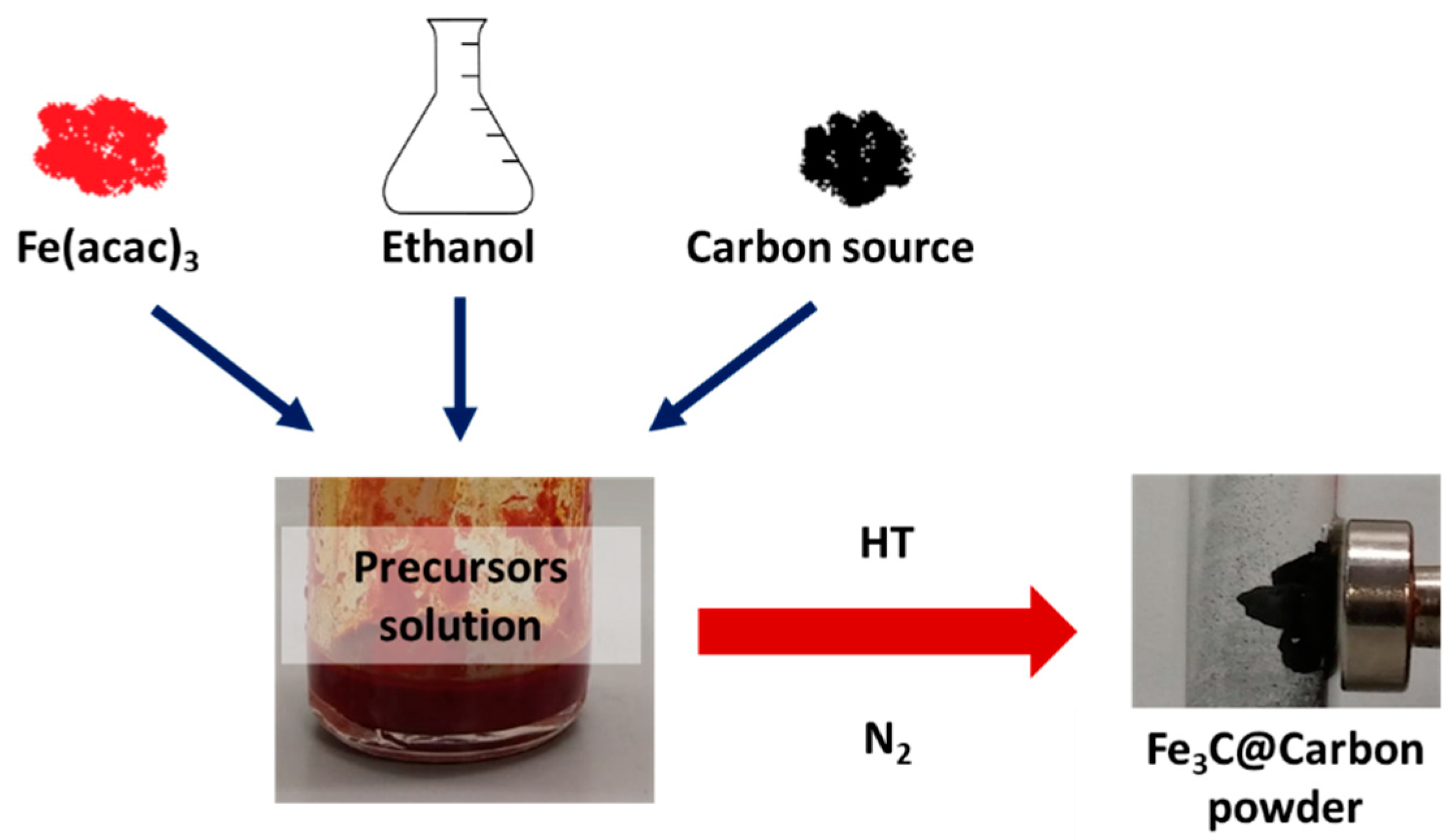
Iron(III) acetylacetonate (1 g, Fe(acac)3, Sigma-Aldrich 97%, F300, Gillingham, UK) was used as iron source and mixed with approximately 2.5 mL of ethanol to obtain a clear solution. The solution was then mixed with a suitable carbon source to obtain the final iron carbide upon heat treatment. As carbon source, several compounds were explored, going from small molecules such as urea (CO(NH2)2, Sigma-Aldrich 99%, U5128), to sugars such as D-glucose (analytical reagent grade, Fisher Scientific,10391201, Loughborough, UK), D(+)-sucrose (analytical reagent grade, Fisher Scientific, 10647421), and chitosan (MW: 100,000–300,000, VWR, ACRO349050500) but also a polymer-based sugar such as cellulose (Sigmacell, Type 20, 20 μm Sigma-Aldrich, S3504). The cellulose was heat treated prior to its utilization (21 °C/min ramping until 800 °C under N2 flow, no dwelling) to remove possibly absorbed molecules on its surface.
The carbon source strongly affects the texture of the carbon matrix, the composition of the final material but also its surface area and porosity. Specific synthetic details are reported in Table 1, while Figure 1 reports the chemical structure of the several carbon sources used.
For chitosan and cellulose samples, the percentage reported refers to wt % between iron precursors and carbon source.
The heat treatment (up to 800 °C for 2 h under nitrogen flow) leads to a black (matt or shiny depending on the carbon source) powder made of crystalline Fe3C and carbon, as ascertained by X-ray investigation. In some cases, the presence of Fe0 was also observed (see PXRD patterns vide infra). A representation of the procedure is reported in Scheme 2.
2.2. Dyes and Oil Uptake Procedure
Methyl orange (Sigma-Aldrich, ACS reagent, dye content 85%, 114,510) and methylene blue (Sigma-Aldrich, ≥97.0%, 66,720) solution were prepared by dissolving the powder of the dye in water to achieve the desired final concentration. Solutions were kept in the dark to reduce natural photodegradation.
As prepared samples powders (around 5 mg) were mixed with the dye solutions (5 mL) and UV–Vis measurements were performed over time to measure the dye concentration.
Vegetable oil (Tesco®, pure sunflower oil) was added to water containing the Fe3C-based sample and the affinity of the compound was recorded by visual inspection.
2.3. Techniques
To evaluate the crystallinity of the samples and the phases present, X-ray powder diffraction (PXRD) measurements were performed on XPERT Panalytical Empyrean Diffractometer (Cu Kα radiation, λ = 0.154 nm, at 45 kV and 40 mA, Malvern Panalytical Ltd, Royston, UK) equipped with an X’Celerator detector.
To obtain information about the morphology and large-scale homogeneity of the samples, scanning electron microscopy (SEM, Thermo Fisher Scientific, Hillsboro, USA) was performed on a FEI inspect F instrument. The samples were loaded on carbon-coated stubs and coated by sputtering an Au prior to imaging.
To observe the size and shape of the particles, transmission electron microscopy (TEM, JEOL (U.K.) Limited, London, UK) was performed on a JEOL 2010 operated at an acceleration voltage of 200 kV. Samples were ground and then suspended in ethanol. One drop of this suspension was put on a holey carbon-coated copper grid of 300 mesh and left to dry.
Elemental analysis was conducted using a Thermo Scientific FLASH 2000 Elemental Analyzer (Thermo Fisher Scientific, Hillsboro, USA). Information about the surface area/CO2 adsorption of the material were obtained using Quantachrome Nova 4200e (Anton Paar GmbH, Graz, Austria). N2 adsorption-desorption isotherms were measured at −196 °C. The samples were degassed at 150 °C under vacuum overnight, prior to the adsorption. BET theory was used to calculate surface area. For the CO2 adsorption experiments, the samples were degassed at 150 °C under vacuum overnight. Measurements were performed at 1 bar and 0 °C.
Magnetic (M vs. H) measurements were performed using a Quantum Design Magnetic Property Measurement System (MPMS, Quantum Design, Inc., San Diego, USA) squid magnetometer. A small quantity of each sample was placed in a gel capsule and this capsule was then placed in a plastic drinking straw. M vs. H data were collected sweeping the magnetic field from +50 kOe (5 T) to −50 kOe, and then back to +50 kOe at T = 300 K. Ultraviolet-visible (UV–Vis, Agilent Technologies LDA UK Limited, Stockport, UK) spectroscopy measurements were performed using Cary 100 Agilent spectrophotometer to measure the absorbance of the dye solutions.
3. Results and Discussion
The crystal structure of the final material was ascertained by PXRD study, using ICDD (PDF4+ version) database. Using urea as carbon source, crystalline iron carbide was obtained (Figure 2, upper pattern) alongside a small amount of amorphous carbon (* marked peak) and Fe0. On the other hand, when cellulose was used as C source, the peak of carbon is more defined and prominent, indicating the formation of a quasi-crystalline (possibly turbostratic) phase, alongside the pattern of iron carbide. In this case, the presence of metallic iron was not observed. For the cellulose sample, the increased background at lower angles could be due to the presence of amorphous carbon.
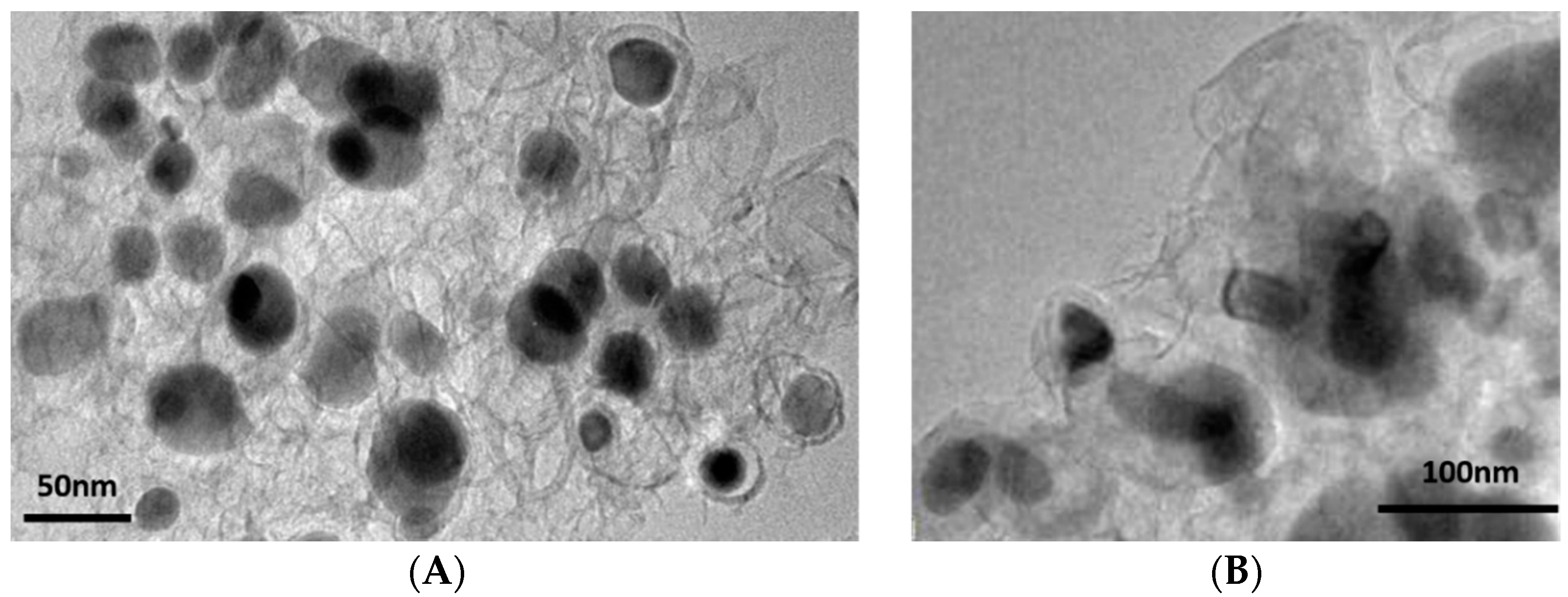
The presence of the carbon matrix seems to affect, also, the final size of the iron carbide nanoparticles, which appeared to be bigger than in the presence of urea (as ascertained by Scherrer calculation of the mean crystallite size and also observed by TEM investigation, Figure 3). The presence of the carbon matrix drastically increases the surface area of the sample prepared with cellulose, which was determined to be above 200 m2/g, against the lesser value of 50 m2/g for the sample prepared using urea (see Table 2). On the other hand, the magnetization of the sample prepared via urea was much higher than that observed for the cellulose-derived sample (100 emu/g vs. <20 emu/g, see Table S1), which means a better suitability of the former for application where magnetization plays the main role, while cellulose-derived samples are more suitable for applications where surface area is crucial.
In the case of urea and cellulose, from the TEM images, it can be seen that the inorganic nanoparticles (metallic in nature, i.e., with higher electron density and therefore showing higher contrast) are distributed on a matrix, possibly turbostratic carbon, in line with PXRD observation (broad carbon peak around 26° 2θ). These results are similar to what reported previously, where the catalytic graphitization of carbon by iron was also observed [20].
Regarding the SEM study, samples prepared using urea and cellulose as carbon source form a quite compact structure, where “wrapped” structures can be also observed (Figure S2). These rods could be due to thin sheets of iron/carbon, which wrap into rods, as previously observed [9].
In order to investigate the role of the carbon source in the formation of a carbon functional matrix, cellulose was replaced with simple sugar molecules, such as glucose and sucrose.
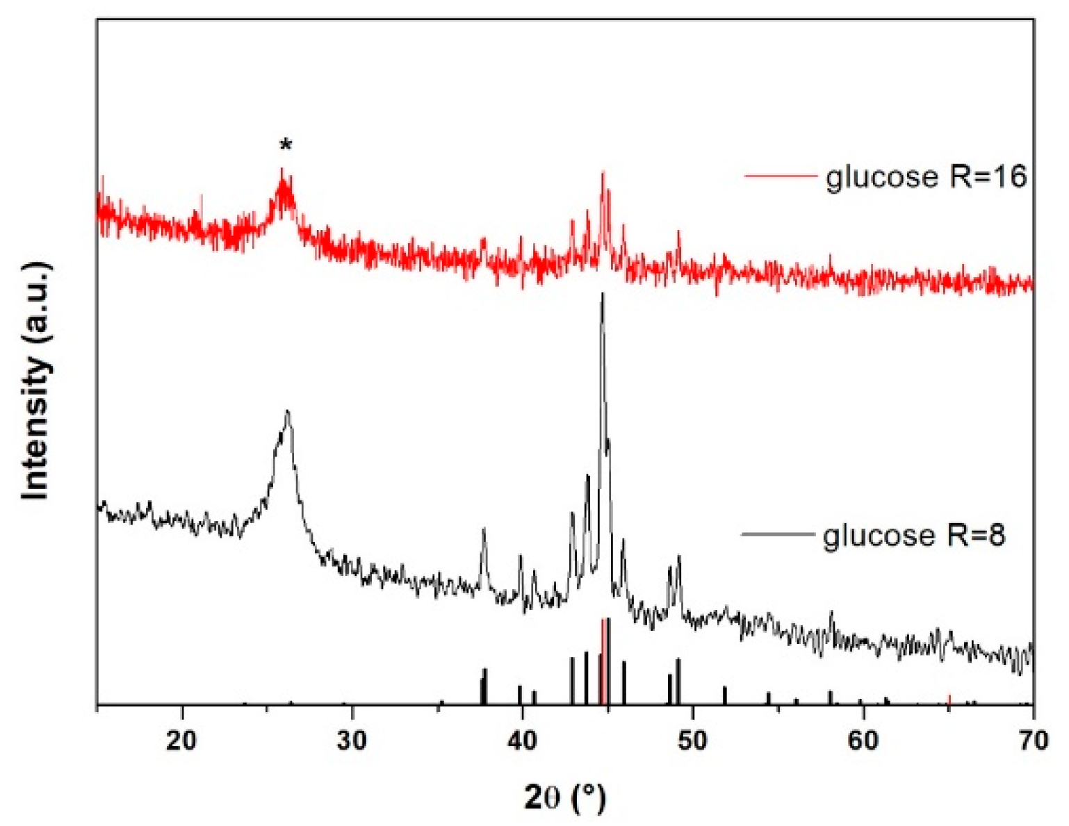
A similar trend to the cellulose-derived samples was observed when glucose was used as carbon source. Also in this case, both iron carbide and carbon peaks are observed (Figure 4). From Figure 4, it can be seen that for higher R, the carbon peak is less intense and broader while, for lower urea/metal ratio (R), residual Fe0 is observed.
Although glucose is a reducing sugar, a higher amount (i.e., higher R) hinders Fe0 formation, possibly towards the formation of ‘reduced’ phases.
The presence of the carbon matrix imparts, to the glucose-derived samples, a higher surface area (>200 m2/g, see Table 2).
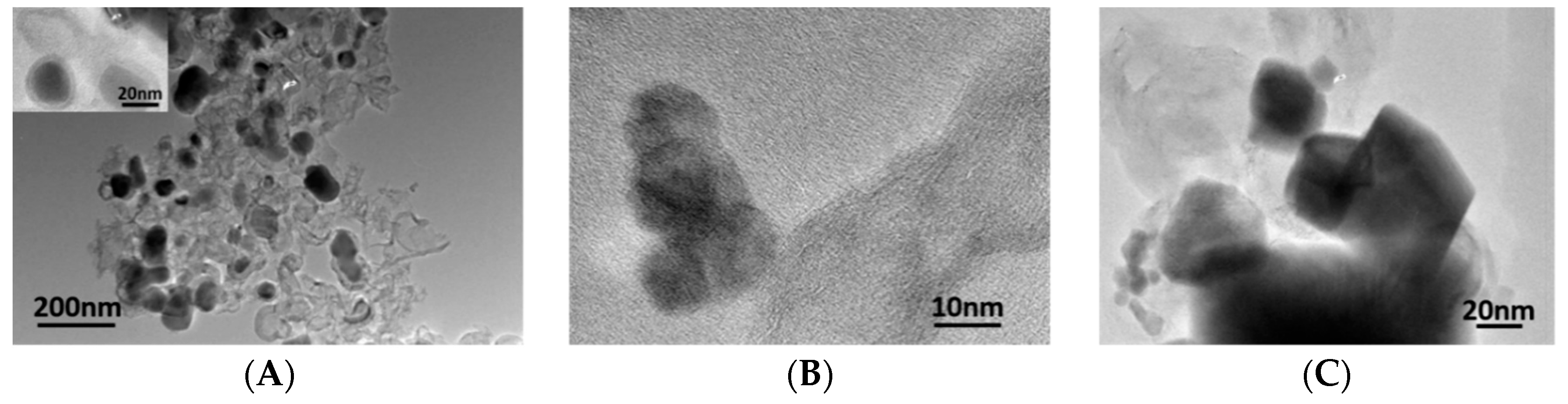
TEM investigation revealed, for both ratios (R = 8 and 16), the formation of medium-sized nanoparticles (20–60 nm on average), mostly agglomerated and ill-shaped, dispersed in the carbon matrix. As expected from the PXRD pattern (see Figure 4), for R = 16, nanoparticles are slightly smaller than for R = 8, but the presence of bigger and ill-shaped aggregates can be also seen (see Figure 5). Interestingly, the lower degree of crystallization for the carbon phase in R = 16 seems to also affect the nanoparticles’ morphology, possibly due to a lack of ‘protection’. In fact, for R = 8, a graphitic carbon shell around the particles was observed, which might act as a protective coating (see inset Figure 5A).
SEM images of the glucose-derived samples are reported in Figure S3, where a rod-like structure can be observed (similar to those observed for the case of the urea-derived sample). Those “needles” are absent in the sample prepared with higher urea/metal ratio (R = 16).
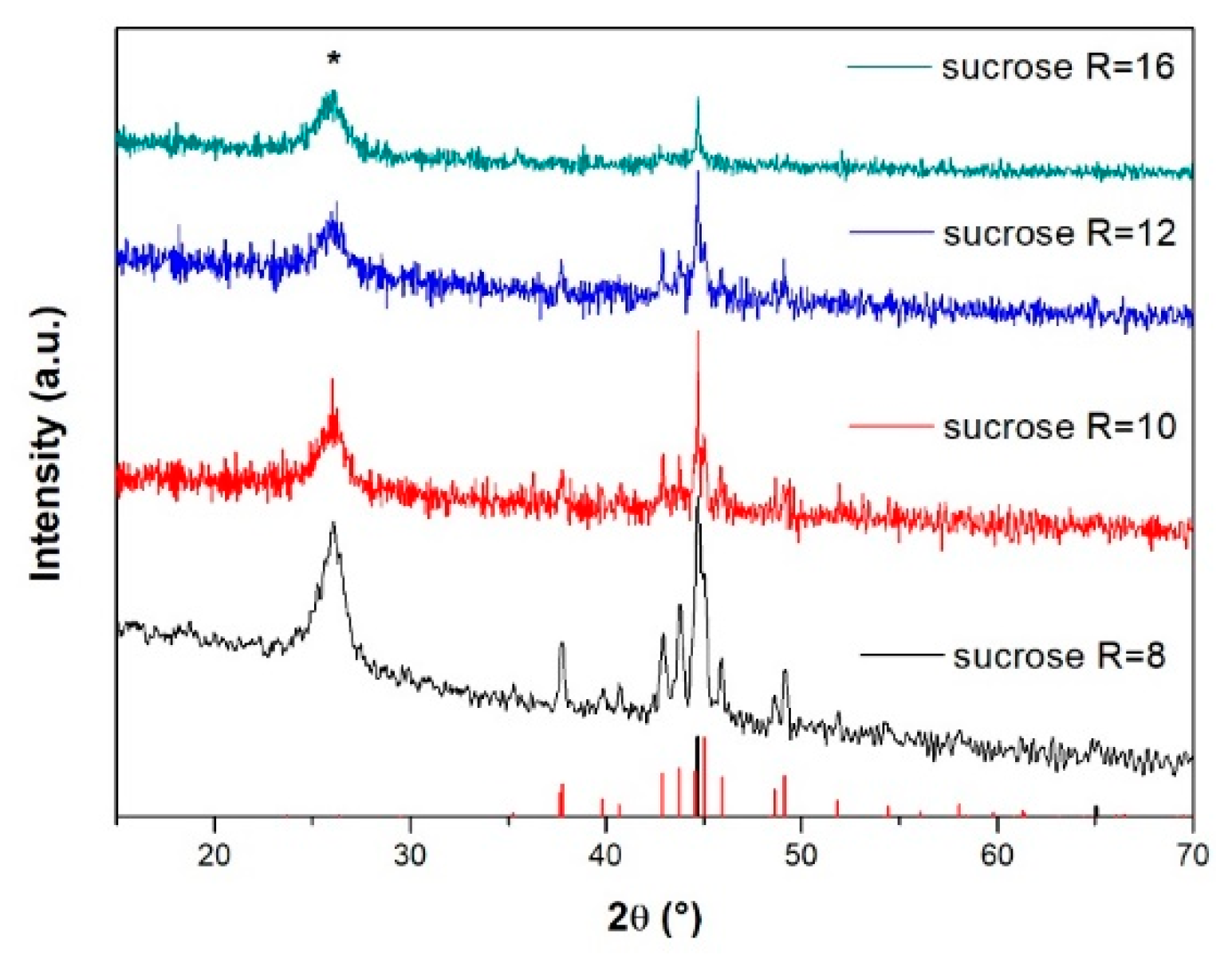
Interestingly, a completely different trend is observed when replacing glucose with sucrose. The use of sucrose as carbon source allows for the formation of iron carbide only at a lower sugar/metal molar ratio, although carbon and a significant amount of iron zero were formed, as ascertained in all cases by PXRD investigation (see Figure 6). The residual metal iron increases with higher R (i.e., the initial sugar amount) to the detriment of the carbide phase, which disappears completely for R ≥ 16. Alongside with increasing R, the peak of carbon also reduces in intensity and becomes broader, indicating that the formation of the iron phase has not supported the graphitization of carbon. The reason behind this trend requires a dedicated study and specific equipment (e.g., EXAFS for in situ measurements), and this is in progress. In any case, SEM study reveals the homogeneity of the samples (see Figure S4).
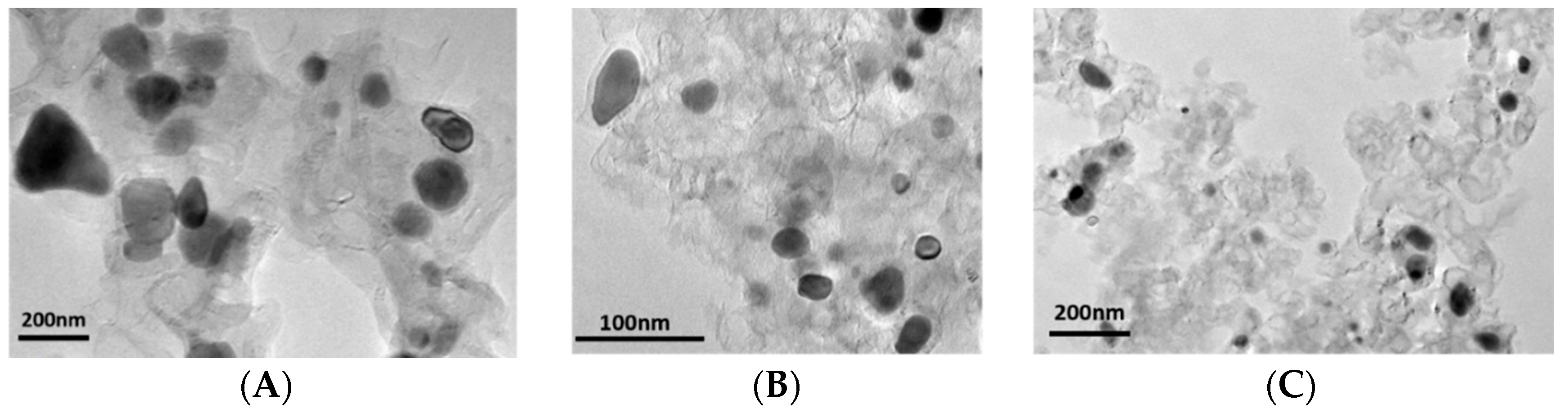
From TEM analysis (Figure 7) the particles of sample R = 8 (Figure 7A) are mostly agglomerated, while, by increasing R, the particles become smaller and less aggregated, for all ratios, and the particles are surrounded by the carbon matrix.
In order to understand whether the initial complexation of the iron source may play a role, chitosan was also explored as a carbon source. Thanks to the presence of NH2 groups, a stronger bonding between chitosan and Fe3+ was expected [21]. Furthermore, chitosan decomposes at lower temperatures compared to cellulose [22].
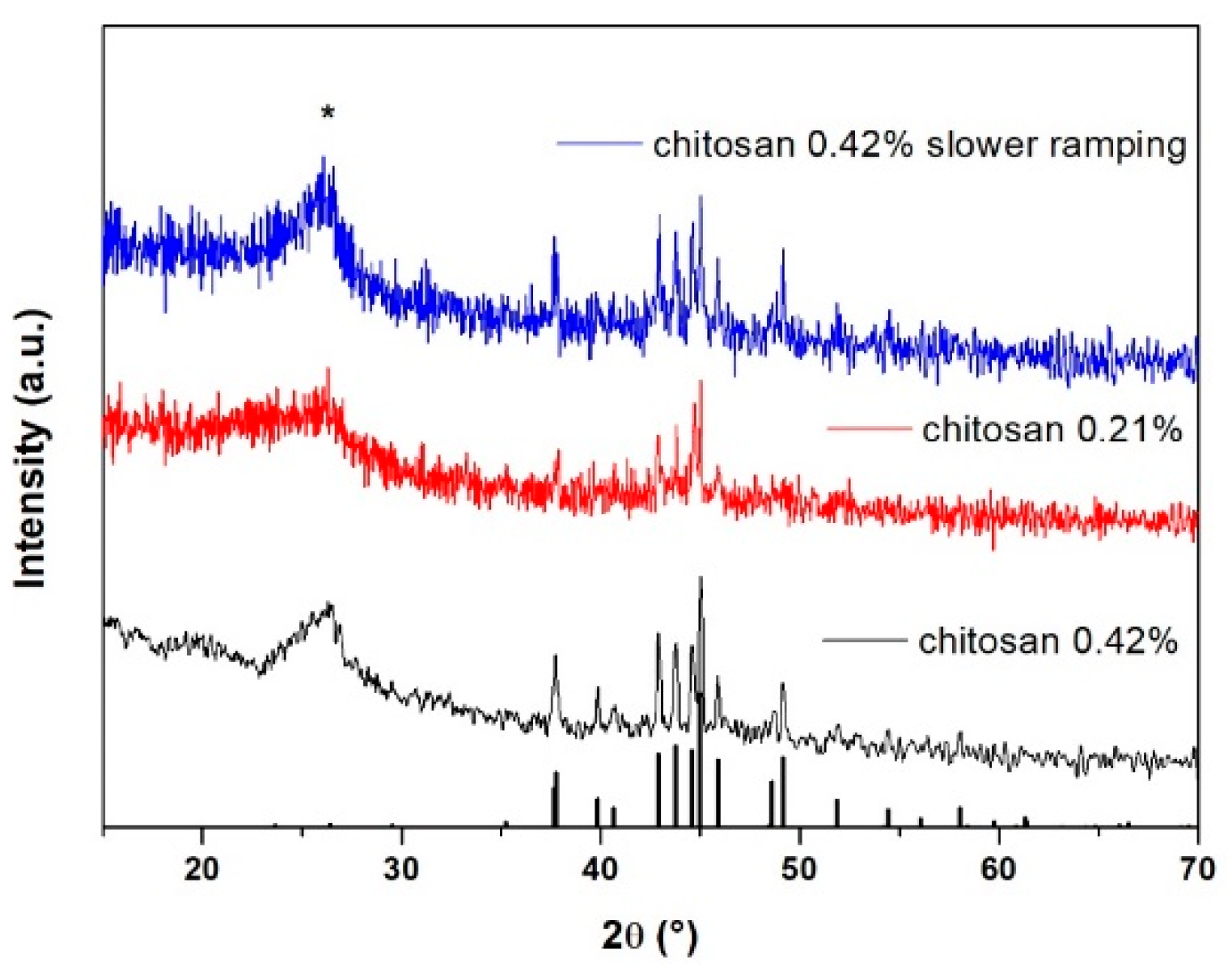
As expected, all samples prepared with chitosan form pure Fe3C, and no Fe0 was observed, although the chitosan/iron molar ratio had no influence on the final composition of the sample, as well as the heating rate. PXRD patterns of the chitosan samples are reported in Figure 8.
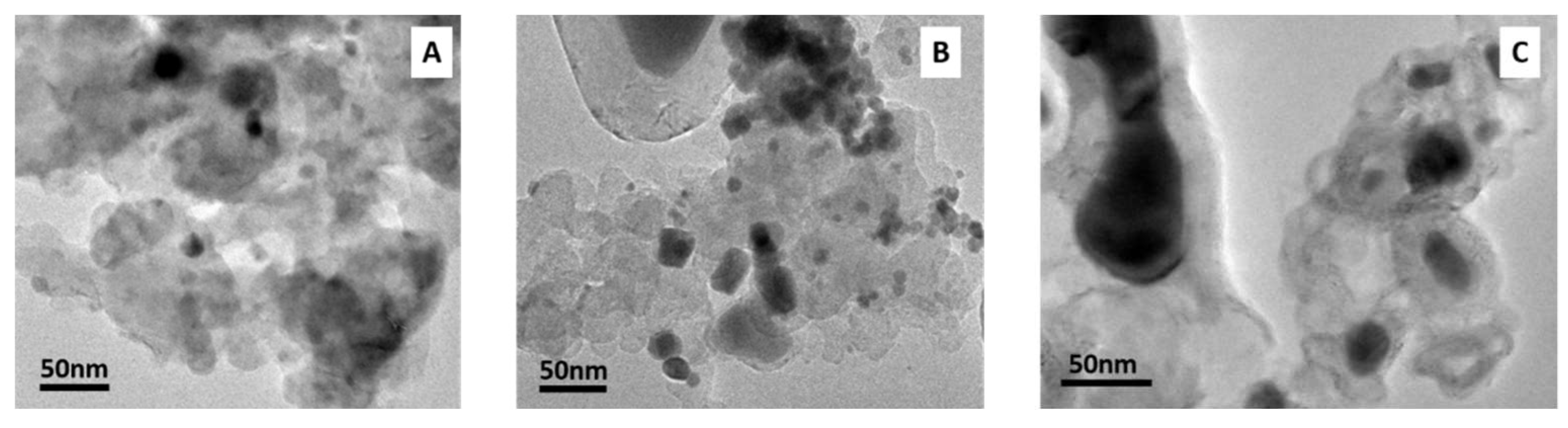
On the other hand, the sample’s lack of homogeneity and carbon phase looks less defined, compared to the cases described previously. Fe3C nanoparticles (darker spot in the TEM images) are smaller and spheroidal (Figure 9).
SEM images of chitosan samples are reported in Figure S5.
3.1. N2 and CO2 Adsorption Test
N2 adsorption measurements were conducted to measure the surface area of the samples, while CO2 adsorption tests were performed to study the adsorption potential of our materials towards sensors applications. The adsorption capacity (Ca) was calculated using the formula reported below:
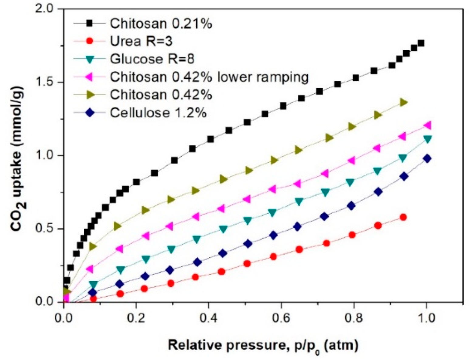
where the volume of gas adsorbed corresponds to the y-axis and, for the adsorption capacity, the maximum value is considered, and molar volume is the volume occupied by one mole of a substance (chemical element or chemical compound) at a given temperature and pressure 1 atm. The obtained values are reported in millimoles of adsorbed gas per gram of the adsorbent. The molar volume of CO2 at standard conditions (273 K and 1 bar) is equal to 22.4 L/mol [23]. The results are reported in Table 2 and Figure 10.
Figure 10 shows that chitosan samples possess higher adsorption ability for CO2. From the comparison of chitosan-derived samples with different chitosan amount, we can safely say that the better adsorbance is not just a question of surface area, with chitosan 0.42% samples having a higher surface area than chitosan 0.21%.
By comparing the results achieved from CO2 adsorption with the results reported in the literature (see Table 3), it can be said that our materials nicely compete with those, with the advantage of being magnetic and, therefore, easily recoverable, but also having potential in magnetic sensor applications.
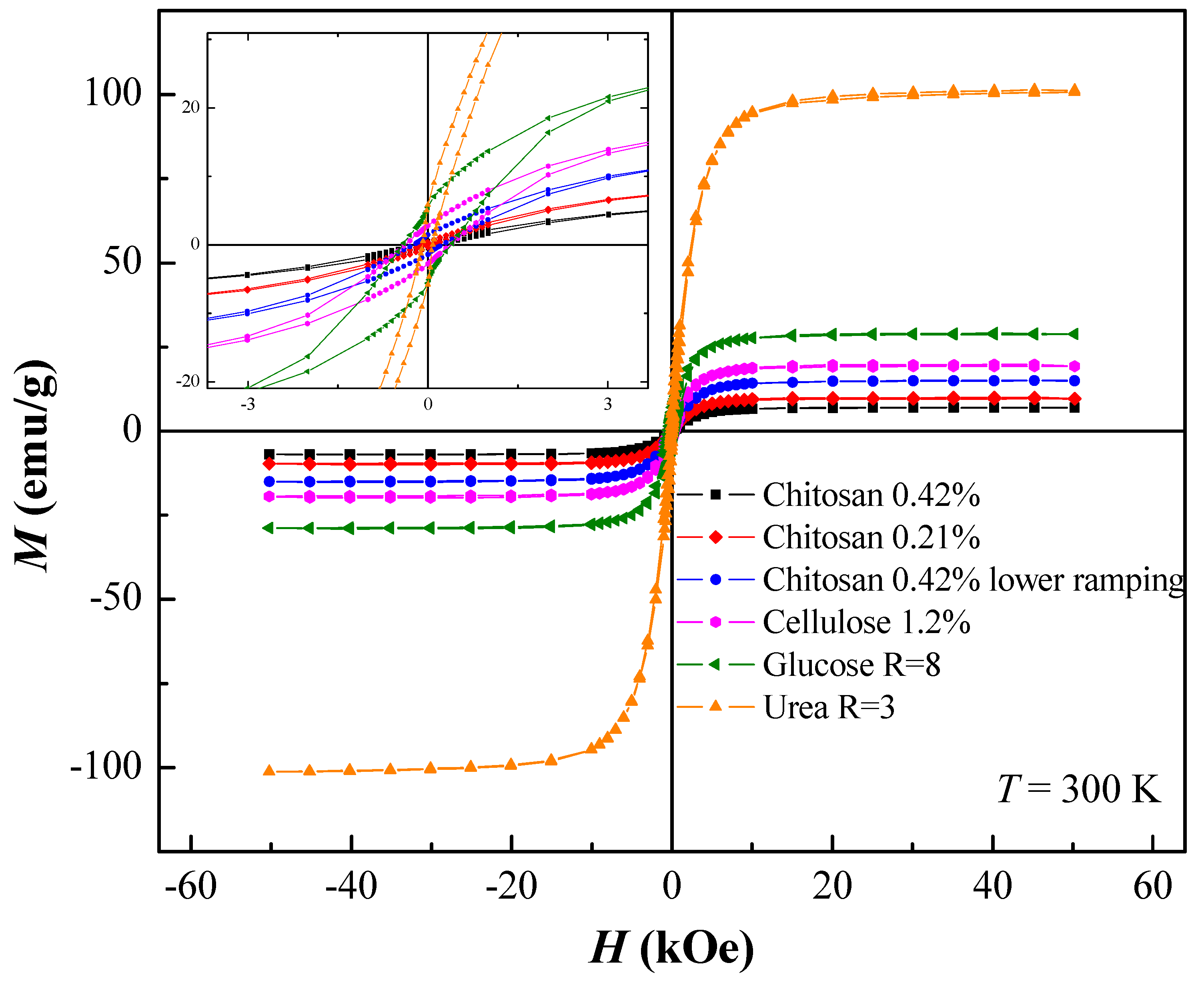
To observe whether the carbon source has an influence on the magnetic behavior of the as-prepared samples, magnetometry measurements were performed at 300 K, and the results reported in Figure 11 and Table S1. Different magnetization behaviors are observed for samples prepared with varying carbon source, as well as metal/C-source ratio which, in turn, means that the different materials have the potential to be used in a range of different applications. The magnetization of all the samples studied was saturated in applied fields above ~10 kOe. The saturation magnetization, σM, varies from 6 emu/g for chitosan 0.42% up to 100 emu/g for urea R = 3 sample. All samples exhibit some magnetic hysteresis (see inset of Figure 11 and Table S1) with coercive fields ranging from 87 up to 400 Oe.
It must be noted that magnetization and magnetic hysteresis are dependent on the amount of carbon present in the sample, and all samples reported here have a comparable magnetic material/carbon ratio by mass (the only exception is the urea sample, with the lowest carbon amount) as reported in Table 1.
3.2. Dyes and Oil Uptake
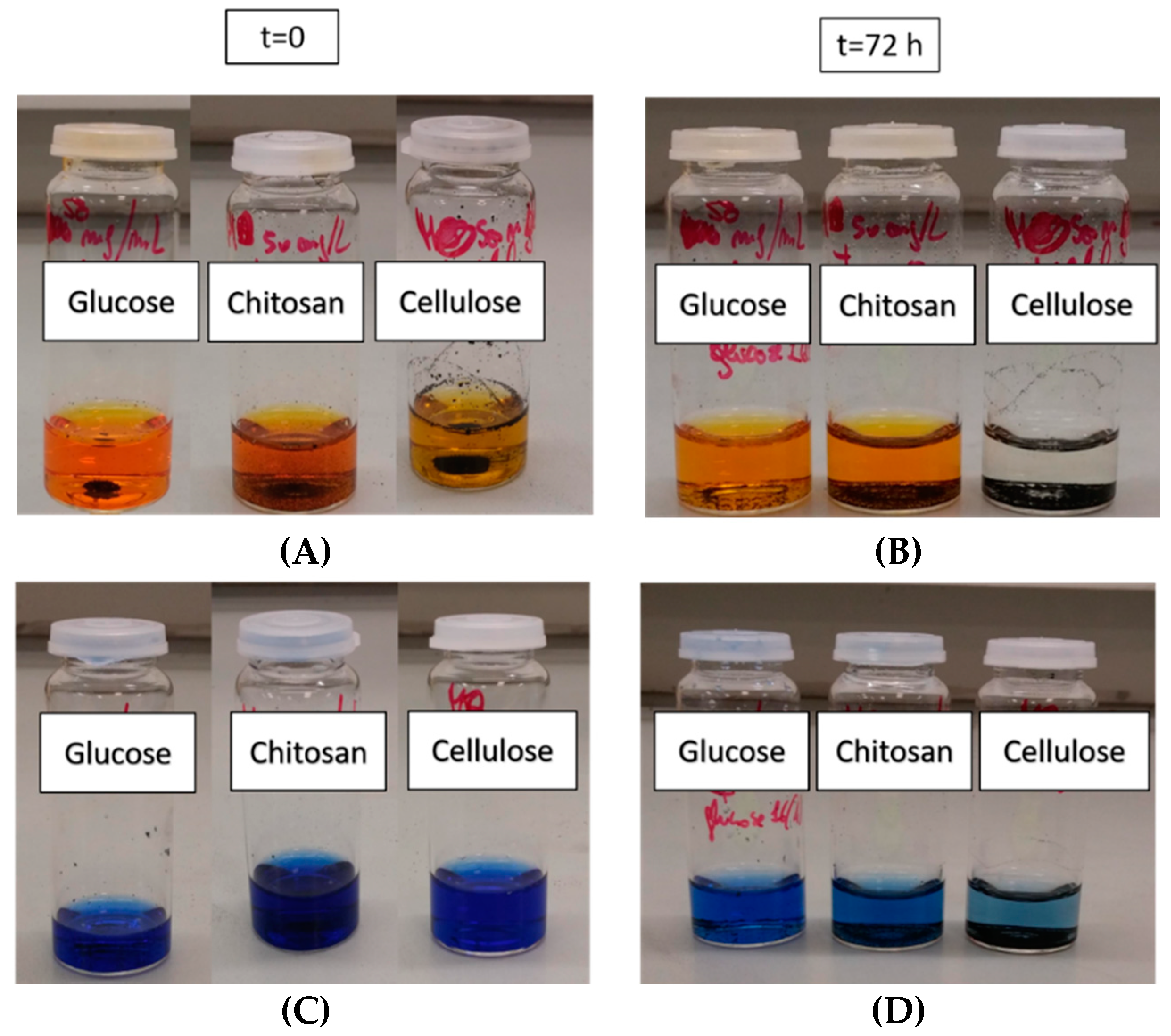
Fe3C-based nanocomposites were tested for possible applications as sorbent for contaminants in wastewater. Samples were treated with two different dyes as model molecules, i.e., methyl orange (MO) and methylene blue (MB). MO and MB were selected as model systems since they are well-known materials and can be easily quantified via UV-Vis spectroscopy.
Furthermore, MB is a cationic dye while MO is an anionic dye. This ensures that the filtration is not solely based on electrostatic interaction.
The solutions initially tested were 50 mg/L both for MO and MB and, after 72 h, a clear solution was obtained for cellulose sample in the case of MO, with a decrease in colour also for MB; such distinct differences were not observed for the other samples tested. The pictures are reported in Figure 12. Fe3C synthesized from cellulose was then believed to be the most promising candidate for dye removal from water.
Clearly, also in this case, surface area does not play the major role, and another factor should be responsible for the uptake.
As an example, the concentration over time calculated from UV–Vis analysis for MO is reported in Figure S6, and a decrease in the concentration of MO was observed for the first few hours, followed by the release of small quantity of dye over time.
To calculate the concentration of MO within the same conditions, a calibration curve was constructed, and the extinction coefficient (ε) was calculated. The calibration curve details can be found in Figure S7. The initial concentration of the solution without Fe3C is 7.64 × 10⁻⁴ M, so almost half of the MO was immediately absorbed in the material.
The recyclability of the compound was tested twice, and the sample was washed several times with water and ethanol to remove all the absorbed dye and dried. In all cases, a large amount of dye was released.
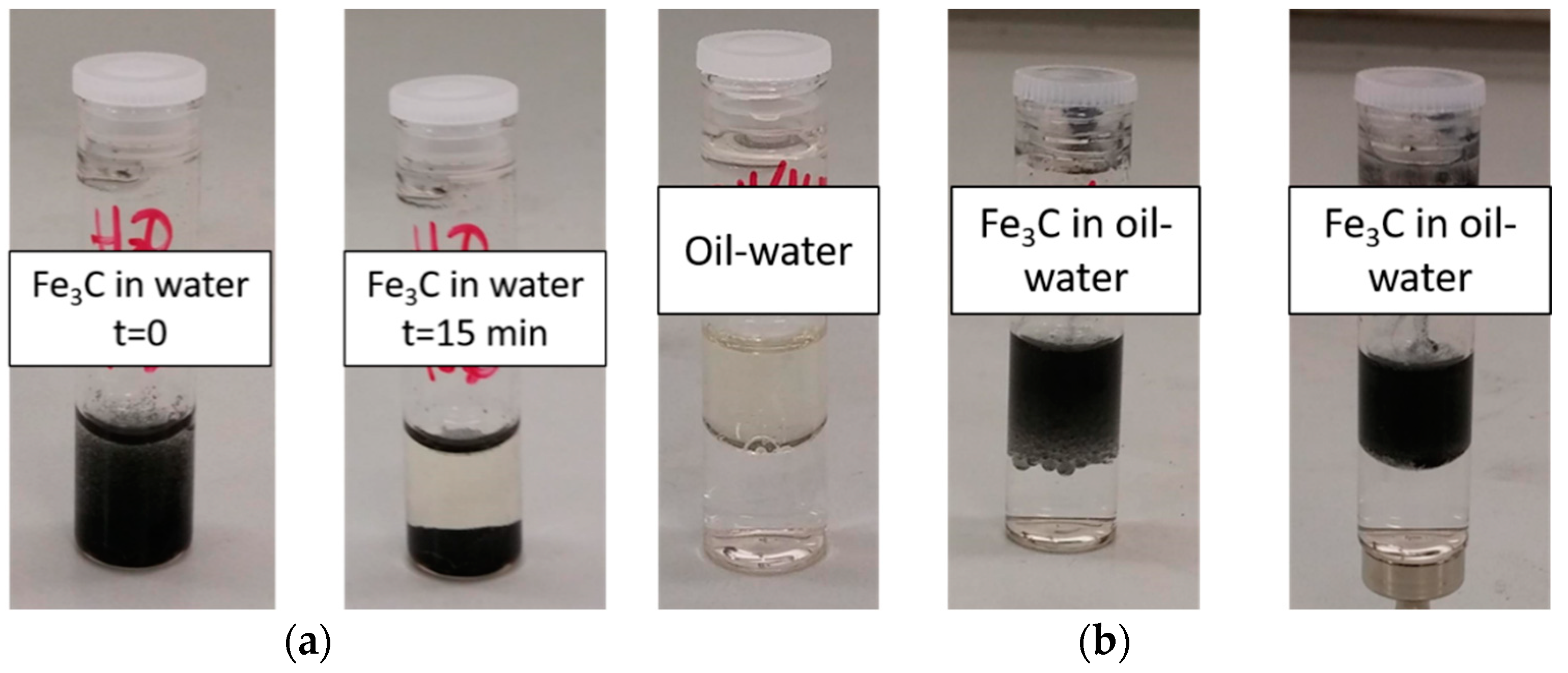
Vegetable oil was also tested as a real example of water contamination since it is commonly poured into the sink when used for cooking. Firstly, the sample was mixed with water and the powder almost immediately deposited on the bottom of the vial, with the addition of the oil, and the Fe3C sample (from cellulose) moved to the hydrophobic phase. When a magnet was moved close to the water phase, no oil mixed with it. The test with oil is reported in Figure 13. This material could then be applied for contaminants in wastewater, such as cooking oil, since it leaves the water ‘clean’.
4. Conclusions
Iron carbide@carbon nanocomposites were prepared using different carbon sources, with the aim of controlling morphology, surface area, and absorption properties of the final material. After characterization, the materials were tested for different applications, such as CO2 adsorption uptake, and dye and oil removal from water. The best CO2 adsorption performance was found for samples prepared from complex carbon source structures, such as chitosan, with a variation in the CO2 uptake by varying the quantity of chitosan used and the heat treatment; this finding is especially interesting because no direct relation with the surface area was observed. Further investigation over the CO2 adsorption behaviour of these samples was also studied to extend Fe3C-based materials for CO2 sensors, especially considering that, to the best of our knowledge, this was the first time where CO2 uptake was reported. Higher saturation magnetization was observed for urea R = 3 sample but, for the other nanocomposites, the presence of extra carbon should be taken into account.
The best sample for dye uptake was the one prepared from cellulose, with an almost immediate uptake of dye by the nanocomposite powder. This sample proved to be also applicable for oil removal from water with no powder present in the water.
Supplementary Materials
The following are available online at https://0-www-mdpi-com.brum.beds.ac.uk/1996-1944/12/2/323/s1, Figure S1: Particles dimension histograms for the samples discussed in the manuscript. (A) urea R = 3, (B) cellulose, (C) glucose R = 8, (D) glucose R = 16, (E) sucrose R = 8, (F) sucrose R = 10, (G) sucrose R = 12, (H) chitosan 0.42%, (I) chitosan 0.21%, (L) 0.42% chitosan with slower rate, Figure S2: SEM images of samples prepared with (A) urea and (B) cellulose respectively, Figure S3: SEM images of samples prepared using glucose with different glucose/iron molar ratio (A) R = 8 and (B) R = 16, Figure S4: SEM images of samples prepared using sucrose with different sugar/iron molar ratio: (A) R = 8; (B) R = 10; (C) R = 12; (D) R = 16, Figure S5: SEM images of samples prepared with different amount of chitosan (A) 0.42%, (B) 0.21%, (C) 0.42% slower heat ramping, Figure S6: Variation in the concentration of MO in cellulose sample over time, Figure S7: Calibration curve for methyl orange, in the insert details of the linear regression are reported, Table S1: Coercive field, Hc, and the saturation magnetization, σM, per gram at T = 300 K for the different samples studied.
Author Contributions
Conceptualization, C.D. and C.G.; Methodology, C.D., M.O.A.M., S.A.N., M.R.L. and C.G.; Validation, C.D. and C.G.; Formal Analysis, C.D., S.A.N. and C.G.; Investigation, C.D., M.O.A.M, S.A.N. and M.R.L.; Resources, C.G.; Data Curation, C.D., S.A.N.; Writing–Original Draft Preparation, C.D. and C.G.; Writing–Review and Editing, C.D. and C.G.; Supervision, C.G.; Project Administration, C.G.
Funding
This research received no external funding.
Acknowledgments
SEM and TEM experimental data were provided by the Nanovision Department of the QMUL. XRD experimental data were provided by the Material Research Institute of the QMUL. N2 and CO2 adsorption were provided by the School of Engineering and material science of QMUL. Magnetic measurements were provided by the Department of Physics, University of Warwick. C.G. and C.D. are grateful to Titirici group for the N2 and CO2 adsorption measurements. C.G. and C.D. acknowledge the QMUL for financial support.
Conflicts of Interest
The authors declare no conflict of interest.
References
- Pigott, V.C. The Archaeometallurgy of the Asian old World; University of Pennsylvania Museum of Archaeology and Anthropology: Philadelphia, PA, USA, 1999; ISBN 0924171340. [Google Scholar]
- Johnson, D.; Tyldesley, J.; Lowe, T.; Withers, P.J.; Grady, M.M. Analysis of a prehistoric Egyptian iron bead with implications for the use and perception of meteorite iron in ancient Egypt. Meteorit. Planet. Sci. 2013, 48, 997–1006. [Google Scholar] [CrossRef] [Green Version]
- Levin, A.A.; Meyer, D.C.; Reibold, M.; Kochmann, W.; Pätzke, N.; Paufler, P. Microstructure of a genuine Damascus sabre. Cryst. Res. Technol. 2005, 40, 905–916. [Google Scholar] [CrossRef]
- Yu, J.; Chen, F.; Gao, W.; Ju, Y.; Chu, X.; Che, S.; Sheng, F.; Hou, Y. Iron carbide nanoparticles: an innovative nanoplatform for biomedical applications. Nanoscale Horiz. 2017, 2, 81–88. [Google Scholar] [CrossRef]
- Tang, W.; Zhen, Z.; Yang, C.; Wang, L.; Cowger, T.; Chen, H.; Todd, T.; Hekmatyar, K.; Zhao, Q.; Hou, Y.; et al. Fe5 C2 Nanoparticles with high MRI contrast enhancement for tumor imaging. Small 2014, 10, 1245–1249. [Google Scholar] [CrossRef] [PubMed]
- Wang, K.; Qiu, G.; Cao, H.; Jin, R. Removal of chromium (VI) from aqueous solutions using Fe3O4 magnetic polymer microspheres functionalized with amino groups. Materials 2015, 8, 8378–8391. [Google Scholar] [CrossRef] [PubMed]
- Sajitha, E.P.; Prasad, V.; Subramanyam, S.V.; Mishra, A.K.; Sarkar, S.; Bansal, C. Size-dependent magnetic properties of iron carbide nanoparticles embedded in a carbon matrix. J. Phys. Condens. Matter 2007, 19, 46214. [Google Scholar] [CrossRef]
- Giordano, C.; Kraupner, A.; Wimbush, S.C.; Antonietti, M. Iron carbide: An ancient advanced material. Small 2010, 6, 1859–1862. [Google Scholar] [CrossRef]
- Giordano, C.; Kraupner, A.; Fleischer, I.; Henrich, C.; Klingelhöfer, G.; Antonietti, M. Non-conventional Fe3C-based nanostructures. J. Mater. Chem. 2011, 21, 16963. [Google Scholar] [CrossRef]
- Rodriguez, J.A.; Liu, P.; Stacchiola, D.J.; Senanayake, S.D.; White, M.G.; Chen, J.G. Hydrogenation of CO2 to Methanol: Importance of metal–oxide and metal–carbide interfaces in the activation of CO2. ACS Catal. 2015, 5, 6696–6706. [Google Scholar] [CrossRef]
- Sharma, S.; Madou, M. A new approach to gas sensing with nanotechnology. Philos. Trans. A Math. Phys. Eng. Sci. 2012, 370, 2448–2473. [Google Scholar] [CrossRef]
- Mirzaei, A.; Hashemi, B.; Janghorban, K. α-Fe2O3 based nanomaterials as gas sensors. J. Mater. Sci. Mater. Electron. 2016, 27, 3109–3144. [Google Scholar] [CrossRef]
- Matatagui, D.; Kolokoltsev, O.V.; Qureshi, N.; Mejía-Uriarte, E.V.; Saniger, J.M. A magnonic gas sensor based on magnetic nanoparticles. Nanoscale 2015, 7, 9607–9613. [Google Scholar] [CrossRef] [PubMed]
- Su, Y.-C.; Lin, C.T.; Chung, W.Y.; Wu, W.J. A room temperature operated carbon dioxide sensor based on EB-PANI/PEDOT:PSS sensing material. Allsensors 2016, 2016, 23–26. [Google Scholar]
- Gooneratne, C.; Li, B.; Moellendick, T. Downhole applications of magnetic sensors. Sensors 2017, 17, 2384. [Google Scholar] [CrossRef]
- Schliehe, C.; Yuan, J.; Glatzel, S.; Siemensmeyer, K.; Kiefer, K.; Giordano, C. Iron nitride and carbide: From crystalline nanoparticles to stable aqueous dispersions. Chem. Mater. 2012, 24, 2716–2721. [Google Scholar] [CrossRef]
- Zhu, K.; Ju, Y.; Xu, J.; Yang, Z.; Gao, S.; Hou, Y. Magnetic nanomaterials: chemical design, synthesis, and potential applications. Acc. Chem. Res. 2018, 51, 404–413. [Google Scholar] [CrossRef]
- Giordano, C.; Antonietti, M. Synthesis of crystalline metal nitride and metal carbide nanostructures by sol-gel chemistry. Nano Today 2011, 6, 366–380. [Google Scholar] [CrossRef]
- Dhahri, R.; Leonardi, S.G.; Hjiri, M.; Mir, L.E.; Bonavita, A.; Donato, N.; Iannazzo, D.; Neri, G. Enhanced performance of novel calcium/aluminum co-doped zinc oxide for CO2 sensors. Sens. Actuators B Chem. 2017, 239, 36–44. [Google Scholar] [CrossRef]
- Glatzel, S.; Schnepp, Z.; Giordano, C. From paper to structured carbon electrodes by inkjet printing. Angew. Chem. Int. Ed. 2013, 52, 2355–2358. [Google Scholar] [CrossRef]
- Dutta, P.K.; Dutta, J.; Tripathi, V.S. Chitin and chitosan: Chemistry, properties and applications. CSIR 2004, 63, 20–31. [Google Scholar]
- Arora, S.; Lala, S.; Kumar, S.; Kumar, M.; Kumar, M. Comparative degradation kinetic studies of three biopolymers: Chitin, chitosan and cellulose. Arch. Appl. Sci. Res. 2011, 3, 188–201. [Google Scholar]
- Cohen, E.R.; Cvitas, T.; Frey, J.G.; Holström, B.; Kuchitsu, K.; Marquardt, R.; Mills, I.; Pavese, F.; Quack, M.; Stohner, J.; et al. Quantities, Units, and Symbols in Physical Chemistry, 2nd ed.; Blackwell Scientific Publications: Oxford, UK, 1993; ISBN 978-0-632-03583-0. [Google Scholar]
- Li, M.; Huang, K.; Schott, J.A.; Wu, Z.; Dai, S. Effect of metal oxides modification on CO2 adsorption performance over mesoporous carbon. Microporous Mesoporous Mater. 2017, 249, 34–41. [Google Scholar] [CrossRef]
- Kumar, S.; Saxena, S.K. A comparative study of CO2 sorption properties for different oxides. Mater. Renew. Sustain. Energy 2014, 3, 30. [Google Scholar] [CrossRef]
- Younas, M.; Sohail, M.; Leong, L.K.; Bashir, M.J.; Sumathi, S. Feasibility of CO2 adsorption by solid adsorbents: a review on low-temperature systems. Int. J. Environ. Sci. Technol. 2016, 13, 1839–1860. [Google Scholar] [CrossRef]
- Wang, X.; Yu, J.; Cheng, J.; Hao, Z.; Xu, Z. High-temperature adsorption of carbon dioxide on mixed oxides derived from hydrotalcite-like compounds. Environ. Sci. Technol. 2008, 42, 614–618. [Google Scholar] [CrossRef]
- Li, W.; Yang, H.; Jiang, X.; Liu, Q. Highly selective CO2 adsorption of ZnO based N-doped reduced graphene oxide porous nanomaterial. Appl. Surf. Sci. 2016, 360, 143–147. [Google Scholar] [CrossRef]
- Queen, W.L.; Hudson, M.R.; Bloch, E.D.; Mason, J.A.; Gonzalez, M.I.; Lee, J.S.; Gygi, D.; Howe, J.D.; Lee, K.; Darwish, T.A.; et al. Comprehensive study of carbon dioxide adsorption in the metal–organic frameworks M 2 (dobdc) (M = Mg, Mn, Fe, Co, Ni, Cu, Zn). Chem. Sci. 2014, 5, 4569–4581. [Google Scholar] [CrossRef]
- Chen, B.; Ma, G.; Kong, D.; Zhu, Y.; Xia, Y. Atomically homogeneous dispersed ZnO/N-doped nanoporous carbon composites with enhanced CO2 uptake capacities and high efficient organic pollutants removal from water. Carbon 2015, 95, 113–124. [Google Scholar] [CrossRef]
- Yu, C.-H.; Huang, C.-H.; Tan, C.-S. A Review of CO2 capture by absorption and adsorption. Aerosol Air Qual. Res. 2012, 12, 745–769. [Google Scholar] [CrossRef]
Scheme 1.
Overview of the manifold application of iron carbide-based materials.

Figure 1.
Molecular structures of the used carbon sources.

Scheme 2.
Overview of the synthesis of Fe3C samples.

Figure 2.
PXRD patterns of samples prepared using urea (R = 3, upper pattern) and cellulose (1.2% downer pattern). The expected pattern from the database for pure Fe3C and Fe0 are reported as vertical lines for comparison (Fe3C, black lines, ICDD: 03-065-2413 and Fe0 red lines, ICDD: 01-087-0721. Marked peak (*) is attributed to carbon (ICDD 01-077-7164).

Figure 3.
TEM images of samples prepared with (A) urea R = 3 and (B) cellulose. Particle dimension histograms are reported in Figure S1.
Figure 3.
TEM images of samples prepared with (A) urea R = 3 and (B) cellulose. Particle dimension histograms are reported in Figure S1.

Figure 4.
PXRD pattern of samples prepared using glucose as carbon source with two different glucose/Fe molar ratios (R). The expected pattern from the database for pure Fe3C and Fe0 are also reported as vertical lines for comparison (Fe3C, black lines, ICDD: 03-065-2413 and Fe0 red lines, ICDD: 01-087-0721. The marked peak (*) is attributed to carbon (ICDD 01-077-7164).

Figure 5.
TEM images of samples prepared using glucose as carbon source with different glucose/iron molar ratio (A) and (B) R = 8 and (C) R = 16. Particle dimension histograms are reported in Figure S1.
Figure 5.
TEM images of samples prepared using glucose as carbon source with different glucose/iron molar ratio (A) and (B) R = 8 and (C) R = 16. Particle dimension histograms are reported in Figure S1.

Figure 6.
PXRD pattern of samples prepared with sucrose at different molar ratios (R). The expected pattern from the database for pure Fe3C and Fe0 are also reported as vertical lines for comparison (Fe3C, red lines, ICDD: 03-065-2413, and Fe0 black lines, ICDD: 01-087-0721. The marked peak (*) is attributed to carbon (ICDD 01-077-7164).

Figure 7.
TEM images of samples prepared with sucrose (A) R = 8, (B) R = 10, and (C) R = 12. Particle dimension histograms are reported in Figure S1.
Figure 7.
TEM images of samples prepared with sucrose (A) R = 8, (B) R = 10, and (C) R = 12. Particle dimension histograms are reported in Figure S1.

Figure 8.
PXRD pattern of samples prepared with chitosan. The expected pattern from the database for pure Fe3C is also reported as vertical lines for comparison (Fe3C, black lines, ICDD: 03-065-2413). Marked peak (*) is attributed to carbon (ICDD 01-077-7164).
Figure 8.
PXRD pattern of samples prepared with chitosan. The expected pattern from the database for pure Fe3C is also reported as vertical lines for comparison (Fe3C, black lines, ICDD: 03-065-2413). Marked peak (*) is attributed to carbon (ICDD 01-077-7164).

Figure 9.
TEM images of samples prepared with different amounts of chitosan (A) 0.42%, (B) 0.21%, and (C) 0.42%, slower heat ramping. Particle dimension histograms are reported in Figure S1.
Figure 9.
TEM images of samples prepared with different amounts of chitosan (A) 0.42%, (B) 0.21%, and (C) 0.42%, slower heat ramping. Particle dimension histograms are reported in Figure S1.

Figure 10.
CO2 uptake vs. p/p0 for different samples.

Figure 11.
M vs. H curves collected at T = 300 K for the different samples.

Figure 12.
Dye sorption on Fe3C samples over time, with a concentration of 50 mg/L both for MO (A,B) and MB (C,D).
Figure 12.
Dye sorption on Fe3C samples over time, with a concentration of 50 mg/L both for MO (A,B) and MB (C,D).

Figure 13.
Pictures of the test of Fe3C sample from cellulose both in water (a) and in a mixture of water and vegetable oil (b). By using a magnet (see bottom of Fe3C in oil-water solution, picture on the far right), the contaminant is not carried into the water.
Figure 13.
Pictures of the test of Fe3C sample from cellulose both in water (a) and in a mixture of water and vegetable oil (b). By using a magnet (see bottom of Fe3C in oil-water solution, picture on the far right), the contaminant is not carried into the water.


Table 1.
Experimental details of samples prepared using different carbon sources and heat-treated at 800 °C under nitrogen flow. R refers to the molar ratio between the carbon source and the metal-salt.
Table 1.
Experimental details of samples prepared using different carbon sources and heat-treated at 800 °C under nitrogen flow. R refers to the molar ratio between the carbon source and the metal-salt.
| Carbon Source | Phases Present * | Average Crystallite Size (nm) | Elemental Analysis (wt %) # | |
|---|---|---|---|---|
| by PXRD ** | by TEM | |||
| Urea R = 3 | Fe3C (76%) (Fe0 (24%)) | N/A | 10–30 | N% = 0.15, C% = 41.3 |
| Cellulose 1.2% | Fe3C | 36 | 30–80 | N% = 0, C% = 87 |
| Glucose R = 8 | Fe3C (76%) (Fe0 (24%)) | 1724 (Fe0) | 20–60 | N% = 1, C% = 97.4 |
| Glucose R = 16 | Fe3C | 63 | 15–50 | N% = 0, C% = 90 |
| Sucrose R = 8 | Fe3C (78%) (Fe0 (22%)) | 36 | 10–40 | N/M |
| Sucrose R = 10 | Fe3C (72 (Fe0 (28%)) | 81 | 10–45 | N/M |
| Sucrose R = 12 | Fe3C (71%) (Fe0 (29%)) | 8655 (Fe0) | 10–50 | N/M |
| Chitosan 0.42% | Fe3C | 73 | 10–25 | N% = 2.3, C% = 82.7 |
| Chitosan 0.21% | Fe3C | 60 | 6–30 | N/M |
| Chitosan 0.42% slower heating | Fe3C | 46 | 10–40 | N% = 6, C% = 94 |
*: For the samples including Fe0, the percentages of the two phases, calculated using the software Match!®, are reported between brackets. **: Calculated on the main peak of the Fe3C PXRD pattern using the Scherrer equation. For Fe3C phase, calculation refers to the peak with d value of 2.06682 Å that corresponds to plane (102). For Fe0 phase, calculation refers to the peak with d value of 2.02671 Å that corresponds to plane (110). #:Theoretical value C wt %: 22%. N/M not measured.
Table 2.
Surface area and CO2 adsorption (CO2 ads) values for the samples prepared.
| Carbon Source | Surface Area (m2/g) | Max CO2 ads (mmol/g) |
|---|---|---|
| Urea R = 3 | 43 | 0.58 |
| Cellulose 1.2% | 211 | 0.98 |
| Glucose R = 8 | 239 | 1.11 |
| Chitosan 0.42% | 131 | 1.37 |
| Chitosan 0.21% | 55 | 1.76 |
| Chitosan 0.42% slower heat ramping | 194 | 1.2 |
Table 3.
Reported values of CO2 adsorbed (ads/mmol/g) for different materials.
| Material | Max CO2 ads (mmol/g) (Temperature of Analysis) | Surface Area (m2/g) | Reference |
|---|---|---|---|
| AMC * | 4.66 (273 K) | 2475 | [24] |
| CeO2–AMC | 3.13 (273 K) | 1906 | |
| CuO–AMC | 2.40 (273 K) | 2097 | |
| NiO–AMC | 3.30 (273 K) | 2006 | |
| Mesoporous MgO | 1.82 (not reported) | Not reported | [25] |
| Non-porous MgO | 0.45 (not reported) | Not reported | |
| AC ** | 2.61 (298 K) | Not reported | [26] |
| CNTs | 1.08 (323 K) | Not reported | |
| MgAlO | 1.13 (623 K) | 161 | [27] |
| CaAlO | 0.87 (623 K) | 26 | |
| N–rGO–ZnO | 3.55 (298 K) | 1122 | [28] |
| MOF–Mg *** | 1.1 (298 K) | Not reported | [29] |
| MOF–Cu | 0.48 (298 K) | Not reported | |
| MOF–Fe | 1.1 (298 K) | Not reported | |
| ZnO–nanoporous carbon | 4.42 (273 K) | 706 | [30] |
| MCM-41 | 0.62 (298 K) | 1129 | [31] |
| Meso Al2O3 | 0.84 (298 K) | 271 |
*: AMC = activated mesoporous carbon. **: AC = activated carbon. ***: MOF = metal organic frameworks.
© 2019 by the authors. Licensee MDPI, Basel, Switzerland. This article is an open access article distributed under the terms and conditions of the Creative Commons Attribution (CC BY) license (http://creativecommons.org/licenses/by/4.0/).
Share and Cite
MDPI and ACS Style
Defilippi, C.; Mukadam, M.O.A.; Nicolae, S.A.; Lees, M.R.; Giordano, C. Iron Carbide@Carbon Nanocomposites: A Tool Box of Functional Materials. Materials 2019, 12, 323. https://0-doi-org.brum.beds.ac.uk/10.3390/ma12020323
AMA Style
Defilippi C, Mukadam MOA, Nicolae SA, Lees MR, Giordano C. Iron Carbide@Carbon Nanocomposites: A Tool Box of Functional Materials. Materials. 2019; 12(2):323. https://0-doi-org.brum.beds.ac.uk/10.3390/ma12020323
Chicago/Turabian StyleDefilippi, Chiara, Mariam Omar Ali Mukadam, Sabina Alexandra Nicolae, Martin Richard Lees, and Cristina Giordano. 2019. "Iron Carbide@Carbon Nanocomposites: A Tool Box of Functional Materials" Materials 12, no. 2: 323. https://0-doi-org.brum.beds.ac.uk/10.3390/ma12020323
Note that from the first issue of 2016, this journal uses article numbers instead of page numbers. See further details here.