Effect of Material and Process Specific Factors on the Strength of Printed Parts in Fused Filament Fabrication: A Review of Recent Developments


Abstract
:1. Introduction
2. FFF Materials
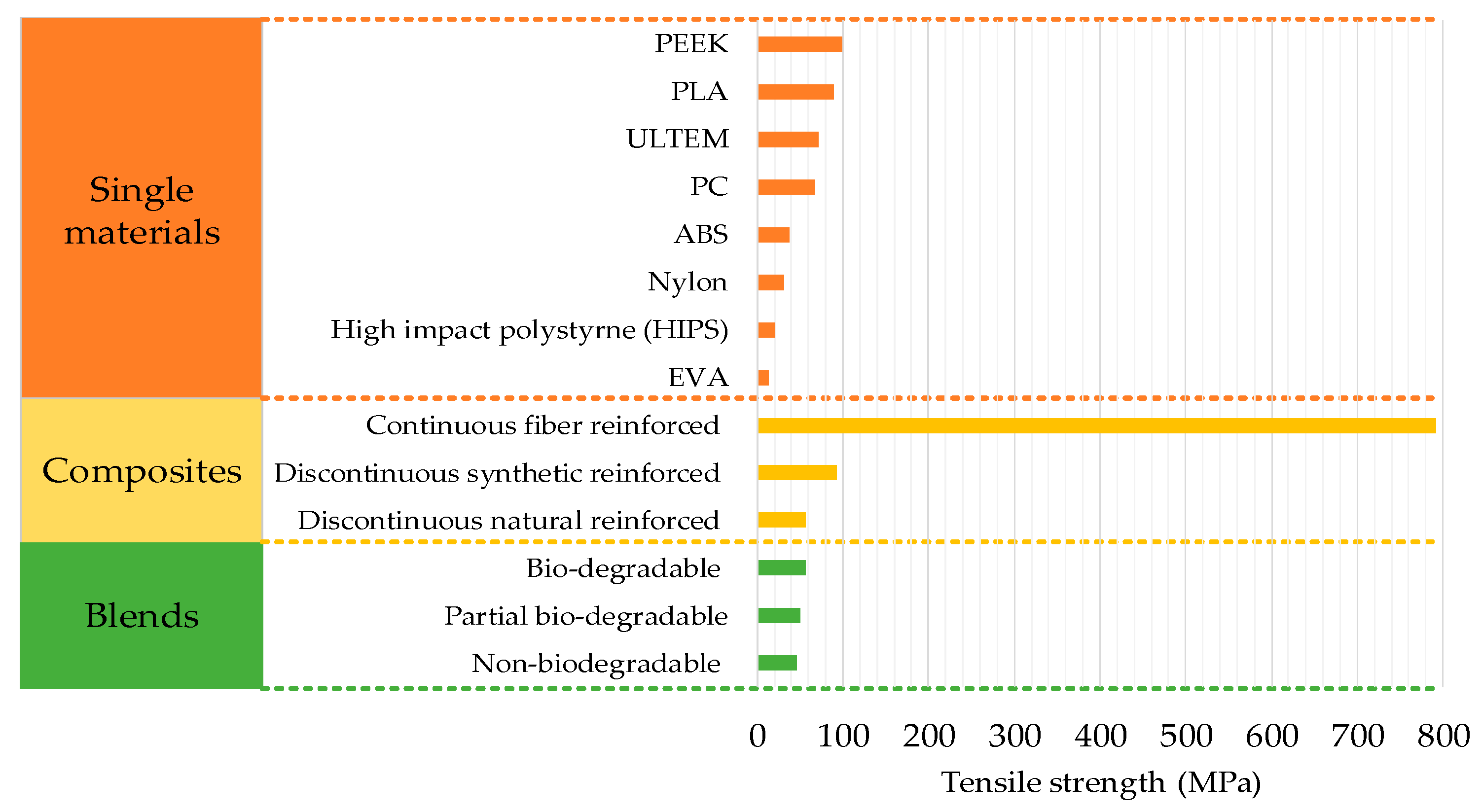
2.1. Single Materials
2.2. Composites
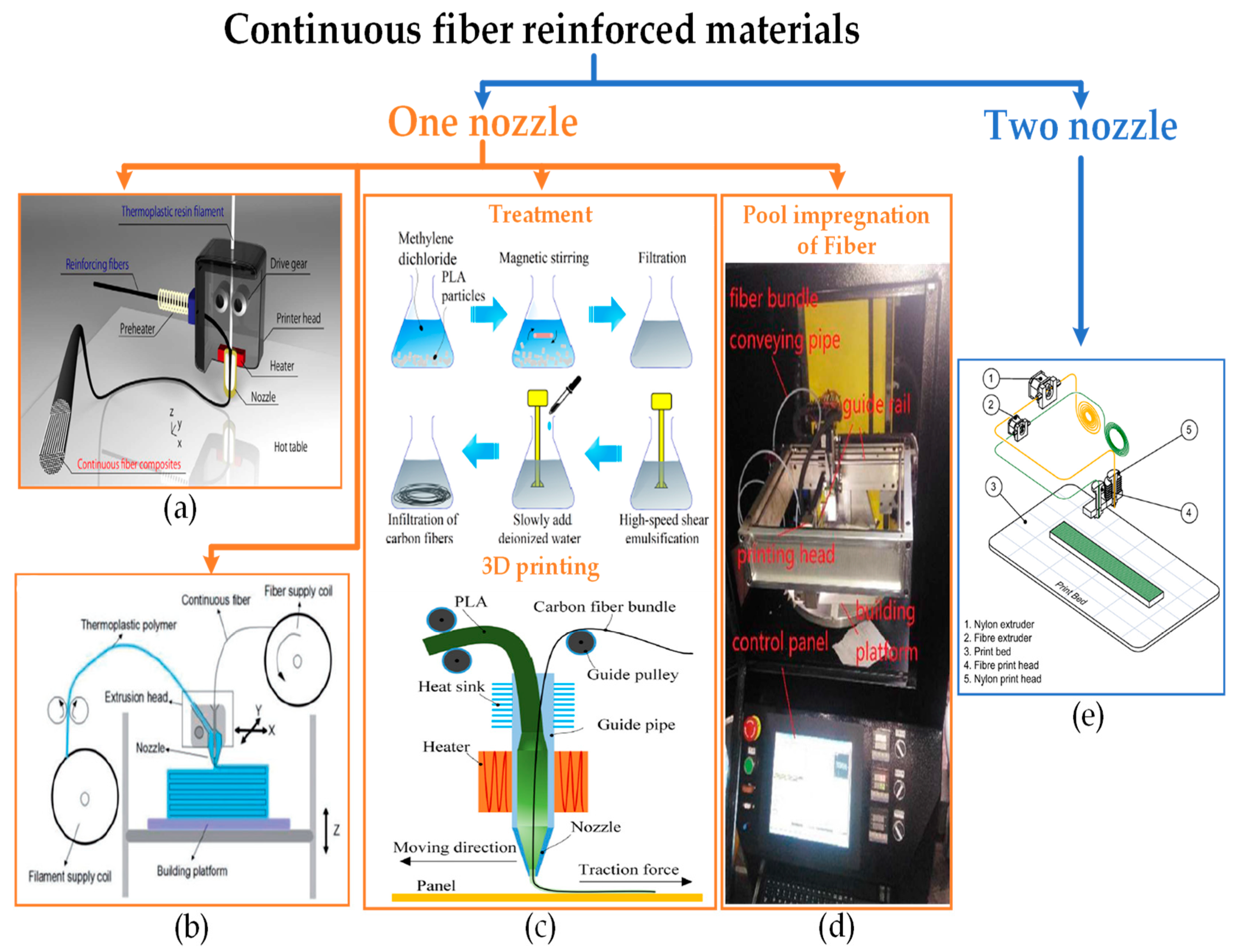
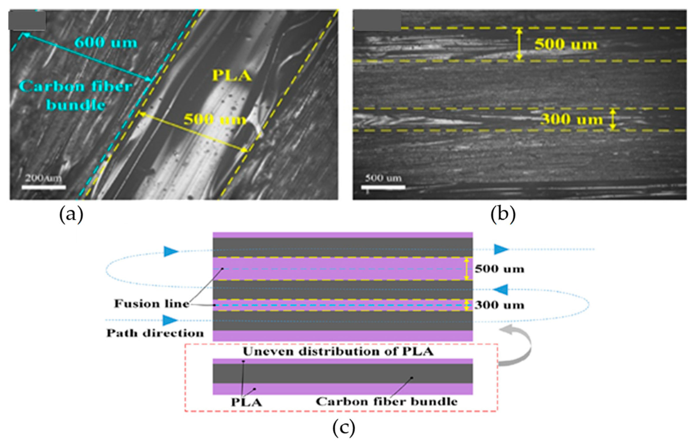
2.2.1. Continuous Fiber Reinforced FFF Materials
2.2.2. Discontinuous Fiber Reinforced FFF Materials
2.3. Blends
3. Summary and Conclusions
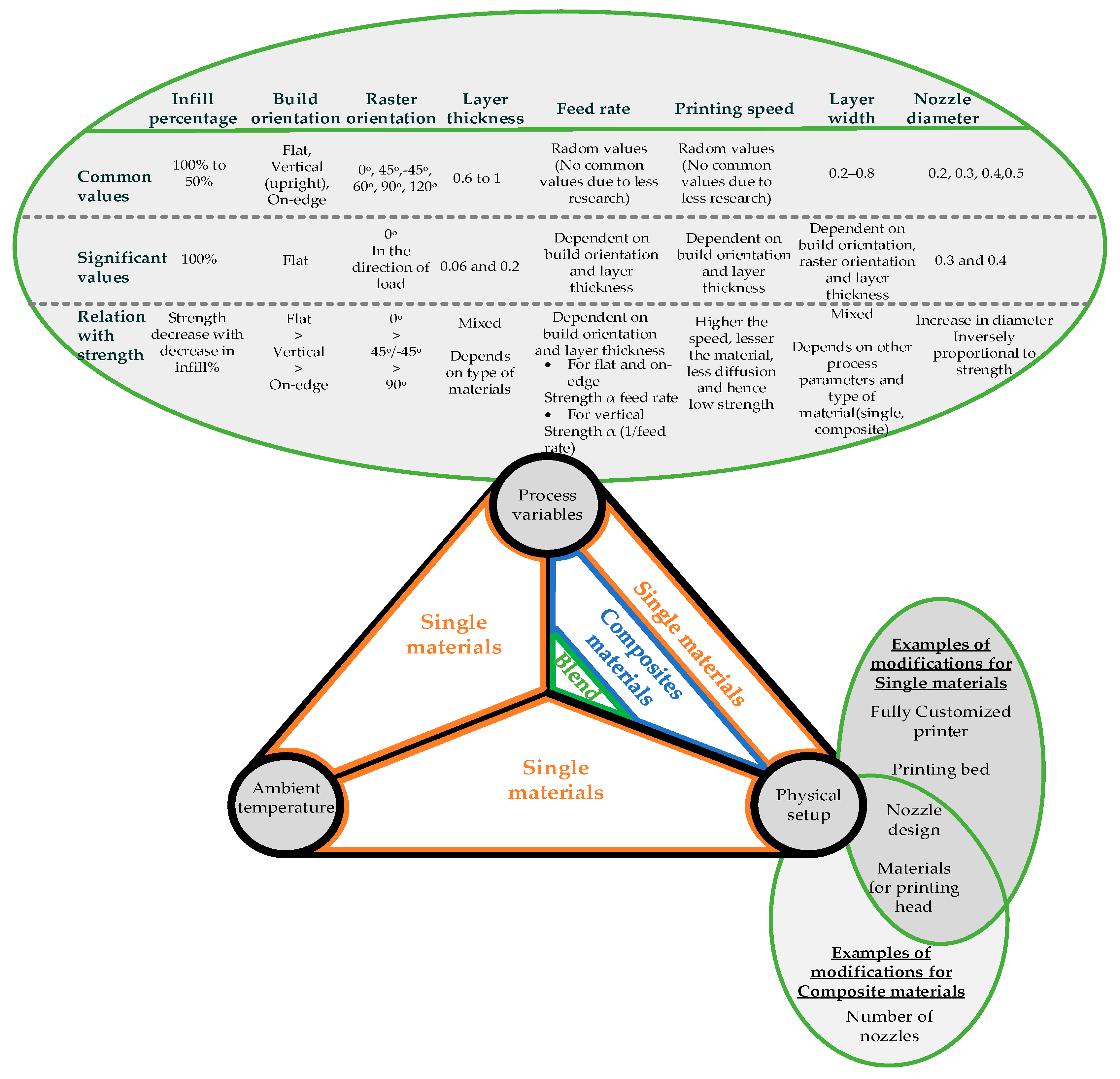
- The basic three types of materials, i.e., single, composites and blends, are analyzed in terms of modifications in process parameters, physical setups and environmental conditions. Furthermore, the above-mentioned three basic types are classified into the sub-categories to explain the modifications in materials that present their true capability.
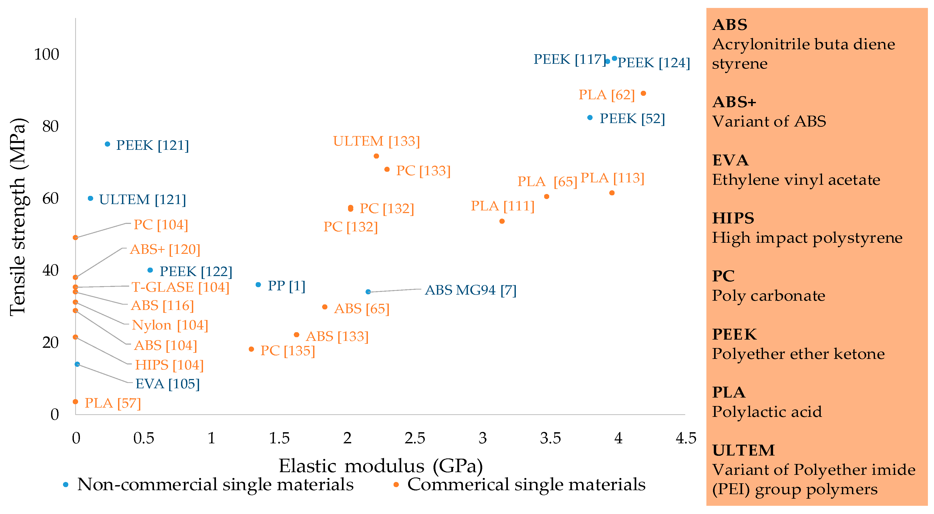
- Single materials are categorized into commercial and non-commercial. Commercial materials are researched more than non-commercial materials. However, non-commercial materials have shown more potential to reach high tensile strength. For example, injection molding grade PEEK has the highest strength of 110 MPa as compared to 89.1 MPa for commercial PLA. Most research on single materials has shown a lack of physical modification of the printing system or temperature control. The research mostly comprises process variables’ optimization. The combination of physical setup modification and ambient temperature still has research potential for Nylon and ULTEM. Furthermore, biodegradable materials such as polycaprolactone (PCL), are not properly investigated for tensile properties as the literature generally reports the compression and flexural properties of PCL in FFF based medical applications.
- Composites are put into two main categories, continuous and discontinuous. Both of which are found in the form of natural and synthetic reinforcements. Discontinuous materials are researched more than continuous. The review provides further segregation of continuous synthetic reinforced composites, and synthetic and natural discontinuous composites with respect to their physical modification and chemical processing. Continuous materials are prominent with the highest strength achieved till now among all FFF/FDM materials. Furthermore, composites are mostly investigated with optimization with process variables and physical setup modifications. Therefore, the effect of ambient temperature is still not fully explored.
- Blends are segregated into three types: biodegradable, non-biodegradable, and partial biodegradable. However, blends are the least researched type of materials in FFF. The highest strength of 58.5MPa has been shown by the partial biodegradable blend. Like composites, blends are not researched in an ambient environment with temperature control. Therefore, this provides a novel area of research to combine this with the other aspects of blends.
- The review highlights the importance of developing novel polymers with less carbon atoms and functional groups instead of blending the printable contemporary materials with the non-printable materials. Furthermore, the review highlights numerous novel research areas regarding three types of materials (single, composites, and blends) as given in Table 7.
Author Contributions
Funding
Conflicts of Interest
References
- Carneiro, O.; Silva, A.; Gomes, R. Fused deposition modeling with polypropylene. Mater. Des. 2015, 83, 768–776. [Google Scholar] [CrossRef]
- Wang, J.; Xie, H.; Weng, Z.; Senthil, T.; Wu, L. A novel approach to improve mechanical properties of parts fabricated by fused deposition modeling. Mater. Des. 2016, 105, 152–159. [Google Scholar] [CrossRef]
- Thomas, D.B.; Hiscox, J.D.; Dixon, B.J.; Potgieter, J. 3D scanning and printing skeletal tissues for anatomy education. J. Anat. 2016, 229, 473–481. [Google Scholar] [CrossRef] [PubMed]
- Wu, C.-S.; Liao, H.-T.; Cai, Y.-X. Characterisation, biodegradability and application of palm fibre-reinforced polyhydroxyalkanoate composites. Polym. Degrad. Stab. 2017, 140, 55–63. [Google Scholar] [CrossRef]
- Gardner, J.M.; Hunt, K.A.; Ebel, A.B.; Rose, E.S.; Zylich, S.C.; Jensen, B.D.; Wise, K.E.; Siochi, E.J.; Sauti, G. Machines as Craftsmen: Localized Parameter Setting Optimization for Fused Filament Fabrication 3D Printing. Adv. Mater. Technol. 2019, 4, 1800653. [Google Scholar] [CrossRef]
- Hsiao, W.-K.; Lorber, B.; Reitsamer, H.; Khinast, J. 3D printing of oral drugs: A new reality or hype? J. Expert Opin. Drug Deliv. 2018, 15. [Google Scholar] [CrossRef]
- Siqueiros, J.G.; Schnittker, K.; Roberson, D.A. ABS-maleated SEBS blend as a 3D printable material. Virtual Phys. Prototyp. 2016, 11, 123–131. (In English) [Google Scholar] [CrossRef]
- Lipson, H.; Kurman, M. Fabricated: The New World of 3D Printing; John Wiley & Sons: Hoboken, NJ, USA, 2013. [Google Scholar]
- Hudson, S.E. Printing teddy bears: A technique for 3D printing of soft interactive objects. In Proceedings of the SIGCHI Conference on Human Factors in Computing Systems, Toronto, ON, Canada, 26 April–1 May 2014; pp. 459–468. [Google Scholar]
- Ready, S.; Endicott, F.; Whiting, G.L.; Ng, T.A.; Chow, E.M.; Lu, J. 3D printed electronics. In Proceedings of the International Conference on Digital Printing Technologies, Seattle, WA, USA, 29 September–3 October 2013; pp. 9–12. [Google Scholar]
- Zhang, Q.; Li, C. The roles of traditional Chinese medicine: Shen-fu injection on the postresuscitation care bundle. Evid.-Based Complement. Altern. Med. 2013, 2013, 319092. [Google Scholar] [CrossRef]
- Garcia, C.; Rumpf, R.; Tsang, H.; Barton, J. Effects of extreme surface roughness on 3D printed horn antenna. Electron. Lett. 2013, 49, 734–736. [Google Scholar] [CrossRef]
- Berman, B. 3-D printing: The new industrial revolution. Bus. Horiz. 2012, 55, 155–162. [Google Scholar] [CrossRef]
- Ahn, S.-H.; Lee, K.-T.; Kim, H.-J.; Wu, R.; Kim, J.-S.; Song, S.-H. Smart soft composite: An integrated 3D soft morphing structure using bend-twist coupling of anisotropic materials. Int. J. Precis. Eng. Manuf. 2012, 13, 631–634. [Google Scholar] [CrossRef]
- Ahmed, N.A.; Page, J. Manufacture of an unmanned aerial vehicle (UAV) for advanced project design using 3D printing technology. Appl. Mech. Mater. 2013, 397, 970–980. [Google Scholar] [CrossRef]
- Richardson, M.; Haylock, B. Designer/maker: The rise of additive manufacturing, domestic-scale production and the possible implications for the automotive industry. Comput.-Aided Des. Appl. PACE 2012, 2, 33–48. [Google Scholar] [CrossRef]
- Hajializadeh, F.; Ince, A. Finite element–based numerical modeling framework for additive manufacturing process. Mater. Des. Process. Commun. 2019, 1, e28. [Google Scholar] [CrossRef]
- Murphy, S.V.; Atala, A. 3D bioprinting of tissues and organs. Nat. Biotechnol. 2014, 32, 773. [Google Scholar] [CrossRef] [PubMed]
- Seliktar, D.; Dikovsky, D.; Napadensky, E. Bioprinting and tissue engineering: Recent advances and future perspectives. Isr. J. Chem. 2013, 53, 795–804. [Google Scholar] [CrossRef]
- Xu, T.; Zhao, W.; Zhu, J.M.; Albanna, M.Z.; Yoo, J.J.; Atala, A. Complex heterogeneous tissue constructs containing multiple cell types prepared by inkjet printing technology. Biomaterials 2013, 34, 130–139. [Google Scholar] [CrossRef]
- Paulsen, S.; Miller, J. Tissue vascularization through 3D printing: Will technology bring us flow? Dev. Dyn. 2015, 244, 629–640. [Google Scholar] [CrossRef]
- Stansbury, J.W.; Idacavage, M.J. 3D printing with polymers: Challenges among expanding options and opportunities. Dent. Mater. 2016, 32, 54–64. [Google Scholar] [CrossRef]
- Schmelzeisen, D.; Koch, H.; Pastore, C.; Gries, T. 4D Textiles: Hybrid Textile Structures that Can Change Structural Form with Time by 3D Printing. In Narrow and Smart Textiles; Springer: Berlin/Heidelberg, Germany, 2018; pp. 189–201. [Google Scholar]
- Melnikova, R.; Ehrmann, A.; Finsterbusch, K. 3D printing of textile-based structures by Fused Deposition Modelling (FDM) with different polymer materials. In IOP Conference Series: Materials Science and Engineering; IOP Publishing: Bristol, UK, 2014; Volume 62, p. 012018. [Google Scholar]
- Grimmelsmann, N.; Kreuziger, M.; Korger, M.; Meissner, H.; Ehrmann, A. Adhesion of 3D printed material on textile substrates. Rapid Prototyp. J. 2018, 24, 166–170. [Google Scholar] [CrossRef]
- Bos, F.; Wolfs, R.; Ahmed, Z.; Salet, T. Additive manufacturing of concrete in construction: Potentials and challenges of 3D concrete printing. Virtual Phys. Prototyp. 2016, 11, 209–225. [Google Scholar] [CrossRef]
- Wu, P.; Wang, J.; Wang, X. A critical review of the use of 3-D printing in the construction industry. Autom. Constr. 2016, 68, 21–31. [Google Scholar] [CrossRef] [Green Version]
- Hager, I.; Golonka, A.; Putanowicz, R. 3D printing of buildings and building components as the future of sustainable construction? Procedia Eng. 2016, 151, 292–299. [Google Scholar] [CrossRef]
- Perkins, I.; Skitmore, M. Three-dimensional printing in the construction industry: A review. Int. J. Constr. Manag. 2015, 15, 1–9. [Google Scholar] [CrossRef] [Green Version]
- Diegel, O.; Xu, W.; Potgieter, J. A case study of rapid prototype as design in educational engineering projects. Int. J. Eng. Educ. 2006, 22, 350. [Google Scholar]
- Wong, K.V.; Hernandez, A. A review of additive manufacturing. ISRN Mech. Eng. 2012, 2012, 208760. [Google Scholar] [CrossRef]
- Campbell, T.A.; Ivanova, O.S. 3D printing of multifunctional nanocomposites. Nano Today 2013, 8, 119–120. (In English) [Google Scholar] [CrossRef]
- Olakanmi, E.O. Selective laser sintering/melting (SLS/SLM) of pure Al, Al-Mg, and Al-Si powders: Effect of processing conditions and powder properties. J. Mater. Process. Technol. 2013, 213, 1387–1405. (In English) [Google Scholar] [CrossRef]
- Bose, S.; Vahabzadeh, S.; Bandyopadhyay, A. Bone tissue engineering using 3D printing. Mater. Today 2013, 16, 496–504. (In English) [Google Scholar] [CrossRef]
- Utela, B.; Storti, D.; Anderson, R.; Ganter, M. A review of process development steps for new material systems in three dimensional printing (3DP). J. Manuf. Process. 2008, 10, 96–104. [Google Scholar] [CrossRef]
- McCullough, E.J.; Yadavalli, V.K. Surface modification of fused deposition modeling ABS to enable rapid prototyping of biomedical microdevices. J. Mater. Process. Technol. 2013, 213, 947–954. (In English) [Google Scholar] [CrossRef]
- Diegel, O.; Withell, A.; de Beer, D.; Potgieter, J.; Noble, F.K. Low-Cost 3D Printing of Controlled Porosity Ceramic Parts. IJAT 2012, 6, 618–626. [Google Scholar] [CrossRef]
- Pereira, T.M.; Potgieter, J.; Kennedy, J. Development of Quality Management Strategies for 3D Printing Testing Methods—A Review. In Proceedings of the 2017 4th Asia-Pacific World Congress on Computer Science and Engineering (APWC on CSE), Nadi, Fiji, 11–13 December 2017; pp. 224–231. [Google Scholar]
- Pereira, T.; Potgieter, J.; Kennedy, J.V. A fundamental study of 3D printing testing methods for the development of new quality management strategies. In Proceedings of the 2017 24th International Conference on Mechatronics and Machine Vision in Practice (M2VIP), Auckland, New Zealand, 21–23 November 2017; pp. 1–6. [Google Scholar]
- Potgieter, J.; Diegel, O.; Noble, F.K.; Pike, M. Additive Manufacturing in the Context of Hybrid Flexible Manufacturing Systems. IJAT 2012, 6, 627–632. [Google Scholar] [CrossRef]
- Whyman, S.; Arif, K.M.; Potgieter, J. Design and development of an extrusion system for 3D printing biopolymer pellets. Int. J. Adv. Manuf. Technol. 2018, 96, 3417–3428. [Google Scholar] [CrossRef]
- Ferreira, A.; Arif, K.M.; Dirven, S.; Potgieter, J. Retrofitment, open-sourcing, and characterisation of a legacy fused deposition modelling system. Int. J. Adv. Manuf. Technol. 2017, 90, 3357–3367. [Google Scholar] [CrossRef]
- Mearns, C.; Potgieter, J.; Dirven, S.; Le Guen, M.J. Experimental analysis of the effectiveness of current modelling methods for SLS parameter determination. In Proceedings of the 2017 24th International Conference on Mechatronics and Machine Vision in Practice (M2VIP), Auckland, New Zealand, 21–23 November 2017; pp. 1–5. [Google Scholar]
- Wjesundera, P.; Schutte, J.; Potgieter, J. The effects of acetone vapour inter-layer processing on fused deposition modelling 3D printed acrylonitrile butadiene styrene. In Proceedings of the 2017 24th International Conference on Mechatronics and Machine Vision in Practice (M2VIP), Auckland, New Zealand, 21–23 November 2017; pp. 1–6. [Google Scholar]
- Khoo, Z.X.; Teoh, J.E.M.; Liu, Y.; Chua, C.K.; Yang, S.; An, J.; Leong, K.F.; Yeong, W.Y. 3D printing of smart materials: A review on recent progresses in 4D printing. Virtual Phys. Prototyp. 2015, 10, 103–122. [Google Scholar] [CrossRef]
- Campbell, I.; Bourell, D.; Gibson, I. Additive manufacturing: Rapid prototyping comes of age. Rapid Prototyp. J. 2012, 18, 255–258. [Google Scholar] [CrossRef]
- Umaras, E.; Tsuzuki, M.S.G. Additive Manufacturing—Considerations on Geometric Accuracy and Factors of Influence. IFAC-PapersOnLine 2017, 50, 14940–14945. [Google Scholar] [CrossRef]
- Loh, G.H.; Pei, E.; Harrison, D.; Monzón, M.D. An overview of functionally graded additive manufacturing. Addit. Manuf. 2018, 23, 34–44. [Google Scholar] [CrossRef] [Green Version]
- Harris, M.; Potgieter, J.; Arif, K.; Archer, R. Large scale 3D printing: Feasibility of novel extrusion based process and requisite materials. In Proceedings of the 2017 24th International Conference on Mechatronics and Machine Vision in Practice (M2VIP), Auckland, New Zealand, 21–23 November 2017; pp. 1–6. [Google Scholar]
- Brenken, B.; Barocio, E.; Favaloro, A.; Kunc, V.; Pipes, R.B. Fused filament fabrication of fiber-reinforced polymers: A review. Addit. Manuf. 2018, 21, 1–16. [Google Scholar] [CrossRef]
- Wang, L.; Gramlich, W.M.; Gardner, D.J. Improving the impact strength of Poly(lactic acid) (PLA) in fused layer modeling (FLM). Polymer 2017, 114, 242–248. [Google Scholar] [CrossRef]
- Arif, M.; Kumar, S.; Varadarajan, K.; Cantwell, W. Performance of biocompatible PEEK processed by fused deposition additive manufacturing. Mater. Des. 2018, 146, 249–259. [Google Scholar] [CrossRef]
- Liao, G.; Li, Z.; Cheng, Y.; Xu, D.; Zhu, D.; Jiang, S.; Guo, J.; Chen, X.; Xu, G.; Zhu, Y. Properties of oriented carbon fiber/polyamide 12 composite parts fabricated by fused deposition modeling. Mater. Des. 2018, 139, 283–292. [Google Scholar] [CrossRef]
- Stoof, D.; Pickering, K. Sustainable composite fused deposition modelling filament using recycled pre-consumer polypropylene. Compos. Part B Eng. 2018, 135, 110–118. [Google Scholar] [CrossRef]
- Zhang, W.; Cotton, C.; Sun, J.; Heider, D.; Gu, B.; Sun, B.; Chou, T.W. Interfacial bonding strength of short carbon fiber/acrylonitrile-butadiene-styrene composites fabricated by fused deposition modeling. Compos. Part B Eng. 2018, 137, 51–59. [Google Scholar] [CrossRef]
- Geng, P.; Zhao, J.; Wu, W.; Ye, W.; Wang, Y.; Wang, S.; Zhang, S. Effects of extrusion speed and printing speed on the 3D printing stability of extruded PEEK filament. J. Manuf. Process. 2019, 37, 266–273. [Google Scholar] [CrossRef]
- Decuir, F.; Phelan, K.; Hollins, B.C. Mechanical Strength of 3-D Printed Filaments. In Proceedings of the 32nd Southern Biomedical Engineering Conference (SBEC), Shreveport, LA, USA, 11–13 March 2016; pp. 47–48. [Google Scholar]
- Cuan-Urquizo, E.; Barocio, E.; Tejada-Ortigoza, V.; Pipes, R.B.; Rodriguez, C.A.; Roman-Flores, A. Characterization of the Mechanical Properties of FFF Structures and Materials: A Review on the Experimental, Computational and Theoretical Approaches. Materials 2019, 12, 895. [Google Scholar] [CrossRef]
- Van Der Klift, F.; Koga, Y.; Todoroki, A.; Ueda, M.; Hirano, Y.; Matsuzaki, R. 3D printing of continuous carbon fibre reinforced thermo-plastic (CFRTP) tensile test specimens. Open J. Compos. Mater. 2015, 6, 18. [Google Scholar] [CrossRef]
- Rankouhi, B.; Javadpour, S.; Delfanian, F.; Letcher, T. Failure Analysis and Mechanical Characterization of 3D Printed ABS With Respect to Layer Thickness and Orientation. J. Fail. Anal. Prev. 2016, 16, 467–481. [Google Scholar] [CrossRef]
- Tian, X.; Liu, T.; Yang, C.; Wang, Q.; Li, D. Interface and performance of 3D printed continuous carbon fiber reinforced PLA composites. Compos. Part A Appl. Sci. Manuf. 2016, 88, 198–205. [Google Scholar] [CrossRef]
- Chacón, J.; Caminero, M.; García-Plaza, E.; Núñez, P. Additive manufacturing of PLA structures using fused deposition modelling: Effect of process parameters on mechanical properties and their optimal selection. Mater. Des. 2017, 124, 143–157. [Google Scholar] [CrossRef]
- Domingo-Espin, M.; Puigoriol-Forcada, J.M.; Garcia-Granada, A.-A.; Lluma, J.; Borros, S.; Reyes, G. Mechanical property characterization and simulation of fused deposition modeling Polycarbonate parts. Mater. Des. 2015, 83, 670–677. [Google Scholar] [CrossRef]
- Sood, A.K.; Ohdar, R.K.; Mahapatra, S.S. Parametric appraisal of mechanical property of fused deposition modelling processed parts. Mater. Des. 2010, 31, 287–295. [Google Scholar] [CrossRef]
- Tymrak, B.; Kreiger, M.; Pearce, J.M. Mechanical properties of components fabricated with open-source 3-D printers under realistic environmental conditions. Mater. Des. 2014, 58, 242–246. [Google Scholar] [CrossRef]
- Casavola, C.; Cazzato, A.; Moramarco, V.; Pappalettere, C. Orthotropic mechanical properties of fused deposition modelling parts described by classical laminate theory. Mater. Des. 2016, 90, 453–458. [Google Scholar] [CrossRef]
- Anitha, R.; Arunachalam, S.; Radhakrishnan, P. Critical parameters influencing the quality of prototypes in fused deposition modelling. J. Mater. Process. Technol. 2001, 118, 385–388. [Google Scholar] [CrossRef]
- Knoop, F.; Schoeppner, V. Mechanical and thermal properties of FDM parts manufactured with polyamide 12. In Proceedings of the 26th Annual International Solid Freeform Fabrication Symposium—An Additive Manufacturing Conference, Austin, TX, USA, 10–12 August 2015; Volume 10, pp. 935–948. [Google Scholar]
- Dul, S.; Fambri, L.; Pegoretti, A. Fused deposition modelling with ABS–graphene nanocomposites. Compos. Part A Appl. Sci. Manuf. 2016, 85, 181–191. [Google Scholar] [CrossRef]
- Shaffer, S.; Yang, K.; Vargas, J.; Di Prima, M.A.; Voit, W. On reducing anisotropy in 3D printed polymers via ionizing radiation. Polymer 2014, 55, 5969–5979. [Google Scholar] [CrossRef]
- Christiyan, K.J.; Chandrasekhar, U.; Venkateswarlu, K. A study on the influence of process parameters on the Mechanical Properties of 3D printed ABS composite. In IOP Conference Series: Materials Science and Engineering; IOP Publishing: Bristol, UK, 2016; Volume 114, p. 012109. [Google Scholar]
- Ning, F.; Cong, W.; Hu, Y.; Wang, H. Additive manufacturing of carbon fiber-reinforced plastic composites using fused deposition modeling: Effects of process parameters on tensile properties. J. Compos. Mater. 2017, 51, 451–462. [Google Scholar] [CrossRef]
- Ayrilmis, N.; Kariz, M.; Kwon, J.H.; Kitek Kuzman, M. Effect of printing layer thickness on water absorption and mechanical properties of 3D-printed wood/PLA composite materials. Int. J. Adv. Manuf. Technol. 2019. [Google Scholar] [CrossRef]
- Valerga, A.P.; Batista, M.; Salguero, J.; Girot, F. Influence of PLA Filament Conditions on Characteristics of FDM Parts. Materials 2018, 11, 1322. [Google Scholar] [CrossRef] [PubMed]
- Du Preez, S.; Johnson, A.; LeBouf, R.F.; Linde, S.J.L.; Stefaniak, A.B.; Du Plessis, J. Exposures during industrial 3-D printing and post-processing tasks. Rapid Prototyp. J. 2018, 24, 865–871. [Google Scholar] [CrossRef]
- Chohan, J.S.; Singh, R. Pre and post processing techniques to improve surface characteristics of FDM parts: A state of art review and future applications. Rapid Prototyp. J. 2017, 23, 495–513. [Google Scholar] [CrossRef]
- Lalehpour, A.; Janeteas, C.; Barari, A. Surface roughness of FDM parts after post-processing with acetone vapor bath smoothing process. Int. J. Adv. Manuf. Technol. 2018, 95, 1505–1520. [Google Scholar] [CrossRef]
- Valerga, A.P.; Batista, M.; Fernandez-Vidal, S.R.; Gamez, A.J. Impact of Chemical Post-Processing in Fused Deposition Modelling (FDM) on Polylactic Acid (PLA) Surface Quality and Structure. Polymers 2019, 11, 566. [Google Scholar] [CrossRef]
- Zaldivar, R.J.; McLouth, T.D.; Patel, D.N.; Severino, J.V.; Kim, H.I. Strengthening of plasma treated 3D printed ABS through epoxy infiltration. Prog. Addit. Manuf. 2017, 2, 193–200. [Google Scholar] [CrossRef] [Green Version]
- Equbal, A.; Sood, A.K. Metallization on FDM Parts Using the Chemical Deposition Technique. Coatings 2014, 4, 574–586. [Google Scholar] [CrossRef] [Green Version]
- Martin, J.H.; Ashby, D.S.; Schaedler, T.A. Thin-walled high temperature alloy structures fabricated from additively manufactured polymer templates. Mater. Des. 2017, 120, 291–297. [Google Scholar] [CrossRef]
- Lavecchia, F.; Percoco, G.; Pei, E.; Galantucci, L.M. Computer Numerical Controlled Grinding and Physical Vapor Deposition for Fused Deposition Modelled Workpieces. Adv. Mater. Sci. Eng. 2018, 2018, 9037490. [Google Scholar] [CrossRef]
- Harris, M.; Potgieter, J.; Archer, R.; Arif, K.M. In-process thermal treatment of polylactic acid in fused deposition modelling. Mater. Manuf. Process. 2019, 34, 701–713. [Google Scholar] [CrossRef]
- Yang, C.; Tian, X.; Li, D.; Cao, Y.; Zhao, F.; Shi, C. Influence of thermal processing conditions in 3D printing on the crystallinity and mechanical properties of PEEK material. J. Mater. Process. Technol. 2017, 248, 1–7. [Google Scholar] [CrossRef]
- Singh, S.; Ramakrishna, S.; Singh, R. Material issues in additive manufacturing: A review. J. Manuf. Process. 2017, 25, 185–200. [Google Scholar] [CrossRef]
- Woodfield, T.B.; Malda, J.; De Wijn, J.; Peters, F.; Riesle, J.; van Blitterswijk, C.A. Design of porous scaffolds for cartilage tissue engineering using a three-dimensional fiber-deposition technique. Biomaterials 2004, 25, 4149–4161. [Google Scholar] [CrossRef] [PubMed]
- Zeng, W.; Lin, F.; Shi, T.; Zhang, R.; Nian, Y.; Ruan, J.; Zhou, T. Fused deposition modelling of an auricle framework for microtia reconstruction based on CT images. Rapid Prototyp. J. 2008, 14, 280–284. [Google Scholar] [CrossRef]
- Zeltinger, J.; Sherwood, J.K.; Graham, D.A.; Müeller, R.; Griffith, L.G. Effect of pore size and void fraction on cellular adhesion, proliferation, and matrix deposition. Tissue Eng. 2001, 7, 557–572. [Google Scholar] [CrossRef]
- Lam, C.X.F.; Mo, X.; Teoh, S.-H.; Hutmacher, D. Scaffold development using 3D printing with a starch-based polymer. Mater. Sci. Eng. C 2002, 20, 49–56. [Google Scholar] [CrossRef]
- Ang, T.H.; Sultana, F.S.A.; Hutmacher, D.W.; Wong, Y.S.; Fuh, J.Y.H.; Mo, X.M.; Loh, H.T.; Burdet, E.; Teoh, S.H. Fabrication of 3D chitosan–hydroxyapatite scaffolds using a robotic dispensing system. Mater. Sci. Eng. C 2002, 20, 35–42. [Google Scholar] [CrossRef]
- Tanase, C.E.; Spiridon, I. PLA/chitosan/keratin composites for biomedical applications. Mater. Sci. Eng. C 2014, 40, 242–247. [Google Scholar] [CrossRef]
- Przybytek, A.; Gubańska, I.; Kucińska-Lipka, J.; Janik, H. Polyurethanes as a Potential Medical-Grade Filament for Use in Fused Deposition Modeling 3D Printers—A Brief Review. Fibres Text. Eastern Eur. 2018, 6, 120–125. [Google Scholar] [CrossRef]
- Tsai, K.J.; Dixon, S.; Hale, L.R.; Darbyshire, A.; Martin, D.; de Mel, A. Biomimetic heterogenous elastic tissue development. NPJ Regen. Med. 2017, 2, 16. [Google Scholar] [CrossRef]
- Grida, I.; Evans, J.R. Extrusion freeforming of ceramics through fine nozzles. J. Eur. Ceram. Soc. 2003, 23, 629–635. [Google Scholar] [CrossRef]
- Zocca, A.; Colombo, P.; Gomes, C.M.; Günster, J. Additive manufacturing of ceramics: Issues, potentialities, and opportunities. J. Am. Ceram. Soc. 2015, 98, 1983–2001. [Google Scholar] [CrossRef]
- Singh Boparai, K.; Singh, R.; Singh, H. Experimental investigations for development of Nylon6-Al-Al2O3 alternative FDM filament. Rapid Prototyp. J. 2016, 22, 217–224. [Google Scholar] [CrossRef]
- Singh, R.; Singh, S.; Fraternali, F. Development of in-house composite wire based feed stock filaments of fused deposition modelling for wear-resistant materials and structures. Compos. Part B Eng. 2016, 98, 244–249. [Google Scholar] [CrossRef]
- Khatri, B.; Lappe, K.; Noetzel, D.; Pursche, K.; Hanemann, T. A 3D-printable polymer-metal soft-magnetic functional composite—Development and characterization. Materials 2018, 11, 189. [Google Scholar] [CrossRef]
- Hohimer, C.J.; Petrossian, G.; Ameli, A.; Mo, C.; Pötschke, P. Electrical conductivity and piezoresistive response of 3D printed thermoplastic polyurethane/multiwalled carbon nanotube composites. In Behavior and Mechanics of Multifunctional Materials and Composites XII; International Society for Optics and Photonics: Bellingham, WA, USA, 2018; Volume 10596, p. 105960J. [Google Scholar]
- Klippstein, H.; Diaz De Cerio Sanchez, A.; Hassanin, H.; Zweiri, Y.; Seneviratne, L. Fused deposition modeling for unmanned aerial vehicles (uavs): A review. Adv. Eng. Mater. 2018, 20, 1700552. [Google Scholar] [CrossRef]
- RUMLEY-OUELLETTE, B.J.; WAHRY, J.H.; BAKER, A.M.; BERNARDIN, J.D.; MARCHI, A.N.; TODD, M.D. In situ printing of conductive poly lactic acid strain sensors embedded into additively manufactured parts. Struct. Health Monit. 2017. [Google Scholar] [CrossRef]
- Pranzo, D.; Larizza, P.; Filippini, D.; Percoco, G. Extrusion-based 3D printing of microfluidic devices for chemical and biomedical applications: A topical review. Micromachines 2018, 9, 374. [Google Scholar] [CrossRef]
- Lu, Z.; Cao, J.; Song, Z.; Li, D.; Lu, B. Research progress of ceramic matrix composite parts based on additive manufacturing technology. Virtual Phys. Prototyp. 2019. [Google Scholar] [CrossRef]
- Tanikella, N.G.; Wittbrodt, B.; Pearce, J.M. Tensile strength of commercial polymer materials for fused filament fabrication 3D printing. Addit. Manuf. 2017, 15, 40–47. [Google Scholar] [CrossRef] [Green Version]
- Kumar, N.; Jain, P.K.; Tandon, P.; Pandey, P.M. The effect of process parameters on tensile behavior of 3D printed flexible parts of ethylene vinyl acetate (EVA). J. Manuf. Process. 2018, 35, 317–326. [Google Scholar] [CrossRef]
- Kempin, W.; Franz, C.; Koster, L.C.; Schneider, F.; Bogdahn, M.; Weitschies, W.; Seidlitz, A. Assessment of different polymers and drug loads for fused deposition modeling of drug loaded implants. Eur. J. Pharm. Biopharm. 2017, 115, 84–93. [Google Scholar] [CrossRef] [PubMed]
- Goyanes, A.; Kobayashi, M.; Martinez-Pacheco, R.; Gaisford, S.; Basit, A.W. Fused-filament 3D printing of drug products: Microstructure analysis and drug release characteristics of PVA-based caplets. Int. J. Pharm. 2016, 514, 290–295. [Google Scholar] [CrossRef] [PubMed]
- Wu, W.; Geng, P.; Li, G.; Zhao, D.; Zhang, H.; Zhao, J. Influence of Layer Thickness and Raster Angle on the Mechanical Properties of 3D-Printed PEEK and a Comparative Mechanical Study between PEEK and ABS. Materials 2015, 8, 5834–5846. [Google Scholar] [CrossRef] [PubMed]
- Kotlinski, J. Mechanical properties of commercial rapid prototyping materials. Rapid Prototyp. J. 2014, 20, 499–510. [Google Scholar] [CrossRef]
- Yang, C.; Tian, X.; Liu, T.; Cao, Y.; Li, D. 3D printing for continuous fiber reinforced thermoplastic composites: Mechanism and performance. Rapid Prototyp. J. 2017, 23, 209–215. [Google Scholar] [CrossRef]
- Eujin Pei, D.; Lanzotti, A.; Grasso, M.; Staiano, G.; Martorelli, M. The impact of process parameters on mechanical properties of parts fabricated in PLA with an open-source 3-D printer. Rapid Prototyp. J. 2015, 21, 604–617. [Google Scholar] [Green Version]
- Vaezi, M.; Chua, C.K. Effects of layer thickness and binder saturation level parameters on 3D printing process. Int. J. Adv. Manuf. Technol. 2011, 53, 275–284. [Google Scholar] [CrossRef]
- Song, Y.; Li, Y.; Song, W.; Yee, K.; Lee, K.-Y.; Tagarielli, V. Measurements of the mechanical response of unidirectional 3D-printed PLA. Mater. Des. 2017, 123, 154–164. [Google Scholar] [CrossRef]
- Wach, R.A.; Wolszczak, P.; Adamus-Wlodarczyk, A. Enhancement of Mechanical Properties of FDM-PLA Parts via Thermal Annealing. Macromol. Mater. Eng. 2018, 303, 1800169. [Google Scholar] [CrossRef]
- Rezayat, H.; Zhou, W.; Siriruk, A.; Penumadu, D.; Babu, S. Structure–mechanical property relationship in fused deposition modelling. Mater. Sci. Technol. 2015, 31, 895–903. [Google Scholar] [CrossRef]
- Torrado, A.R.; Shemelya, C.M.; English, J.D.; Lin, Y.; Wicker, R.B.; Roberson, D.A. Characterizing the effect of additives to ABS on the mechanical property anisotropy of specimens fabricated by material extrusion 3D printing. Addit. Manuf. 2015, 6, 16–29. [Google Scholar] [CrossRef]
- Rinaldi, M.; Ghidini, T.; Cecchini, F.; Brandao, A.; Nanni, F. Additive layer manufacturing of poly (ether ether ketone) via FDM. Compos. Part B Eng. 2018, 145, 162–172. [Google Scholar] [CrossRef]
- Huang, B.; Meng, S.; He, H.; Jia, Y.; Xu, Y.; Huang, H. Study of processing parameters in fused deposition modeling based on mechanical properties of acrylonitrile-butadiene-styrene filament. Polym. Eng. Sci. 2019, 59, 120–128. [Google Scholar] [CrossRef]
- Conway, K.M.; Pataky, G.J. Crazing in additively manufactured acrylonitrile butadiene styrene. Eng. Fract. Mech. 2019, 211, 114–124. [Google Scholar] [CrossRef]
- Kucewicz, M.; Baranowski, P.; Małachowski, J.; Popławski, A.; Płatek, P. Modelling, and characterization of 3D printed cellular structures. Mater. Des. 2018, 142, 177–189. [Google Scholar] [CrossRef]
- Vaezi, M.; Yang, S. Extrusion-based additive manufacturing of PEEK for biomedical applications. Virtual Phys. Prototyp. 2015, 10, 123–135. [Google Scholar] [CrossRef]
- Deng, X.; Zeng, Z.; Peng, B.; Yan, S.; Ke, W. Mechanical properties optimization of poly-ether-ether-ketone via fused deposition modeling. Materials 2018, 11, 216. [Google Scholar] [CrossRef]
- TERMOPLASTI, Z.; MODELIRANJE, N. Processing poly (ether etherketone) on a 3D printer for thermoplastic modelling. Mater. Tehnol. 2013, 47, 715–721. [Google Scholar]
- Tseng, J.W.; Liu, C.Y.; Yen, Y.K.; Belkner, J.; Bremicker, T.; Liu, B.H.; Sun, T.J.; Wang, A.B. Screw extrusion-based additive manufacturing of PEEK. Mater. Des. 2018, 140, 209–221. [Google Scholar] [CrossRef]
- Zhao, F.; Li, D.; Jin, Z. Preliminary Investigation of Poly-Ether-Ether-Ketone Based on Fused Deposition Modeling for Medical Applications. Materials 2018, 11, 288. [Google Scholar] [CrossRef] [PubMed]
- Barber, P.; Atkinson, J. The use of tensile tests to determine the optimum conditions for butt fusion welding certain grades of polyethylene, polybutene-1 and polypropylene pipes. J. Mater. Sci. 1974, 9, 1456–1466. [Google Scholar] [CrossRef]
- Wang, L.; Gardner, D.J.; Bousfield, D.W. Cellulose nanofibril-reinforced polypropylene composites for material extrusion: Rheological properties. Polym. Eng. Sci. 2018, 58, 793–801. [Google Scholar] [CrossRef]
- Wang, L.; Gardner, D.J. Effect of fused layer modeling (FLM) processing parameters on impact strength of cellular polypropylene. Polymer 2017, 113, 74–80. [Google Scholar] [CrossRef]
- Sodeifian, G.; Ghaseminejad, S.; Yousefi, A.A. Preparation of Polypropylene/Short Glass Fiber Composite as Fused Deposition Modeling (FDM) Filament. Results Phys. 2019, 12, 205–222. [Google Scholar] [CrossRef]
- Gajdoš, I.; Slota, J.; Spišák, E.; Jachowicz, T.; Tor-Swiatek, A. Structure and tensile properties evaluation of samples produced by Fused Deposition Modeling. Open Eng. 2016, 6, 86–89. [Google Scholar] [CrossRef]
- Puigoriol-Forcada, J.M.; Alsina, A.; Salazar-Martín, A.G.; Gomez-Gras, G.; Pérez, M.A. Flexural Fatigue Properties of Polycarbonate Fused-deposition Modelling Specimens. Mater. Des. 2018, 155, 414–421. [Google Scholar] [CrossRef]
- Salazar-Martin, A.G.; Perez, M.A.; García-Granada, A.-A.; Reyes, G.; Puigoriol-Forcada, J.M. A study of creep in polycarbonate fused deposition modelling parts. Mater. Des. 2018, 141, 414–425. [Google Scholar] [CrossRef]
- Boschetto, A.; Giordano, V.; Veniali, F. 3D roughness profile model in fused deposition modelling. Rapid Prototyp. J. 2013, 19, 240–252. [Google Scholar] [CrossRef]
- Smith, W.C.; Dean, R.W. Structural characteristics of fused deposition modeling polycarbonate material. Polym. Test. 2013, 32, 1306–1312. [Google Scholar] [CrossRef]
- Hill, N.; Haghi, M. Deposition direction-dependent failure criteria for fused deposition modeling polycarbonate. Rapid Prototyp. J. 2014, 20, 221–227. [Google Scholar] [CrossRef]
- Aslanzadeh, S.; Saghlatoon, H.; Honari, M.M.; Mirzavand, R.; Montemagno, C.; Mousavi, P. Investigation on electrical and mechanical properties of 3D printed nylon 6 for RF/microwave electronics applications. Addit. Manuf. 2018, 21, 69–75. [Google Scholar] [CrossRef]
- SAYILAN, A.; KAYNAN, Ö.; YUSİFOVA, A.; CEBECİ, H.; YENİGÜN, E.Ö. Kompozitler için 3D Yazıcı İle Yüksek Performanslı Tekstil Yapılarının Tasarlanması ve Geliştirilmesi. Tekstil ve Mühendis 2017, 24, 13–17. [Google Scholar] [CrossRef]
- Geng, Y.; He, H.; Jia, Y.; Peng, X.; Li, Y. Enhanced through-plane thermal conductivity of polyamide 6 composites with vertical alignment of boron nitride achieved by fused deposition modeling. Polym. Compos. 2019. [Google Scholar] [CrossRef]
- Karsli, N.G.; Aytac, A. Tensile and thermomechanical properties of short carbon fiber reinforced polyamide 6 composites. Compos. Part B Eng. 2013, 51, 270–275. [Google Scholar] [CrossRef]
- Botelho, E.C.; Figiel, Ł.; Rezende, M.C.; Lauke, B. Mechanical behavior of carbon fiber reinforced polyamide composites. Compos. Sci. Technol. 2003, 63, 1843–1855. [Google Scholar] [CrossRef]
- Tezcan, J.; Ozcan, S.; Gurung, B.; Filip, P. Measurement and analytical validation of interfacial bond strength of PAN-fiber-reinforced carbon matrix composites. J. Mater. Sci. 2008, 43, 1612–1618. [Google Scholar] [CrossRef]
- Vautard, F.; Ozcan, S.; Poland, L.; Nardin, M.; Meyer, H. Influence of thermal history on the mechanical properties of carbon fiber–acrylate composites cured by electron beam and thermal processes. Compos. Part A Appl. Sci. Manuf. 2013, 45, 162–172. [Google Scholar] [CrossRef]
- Bettini, P.; Alitta, G.; Sala, G.; Di Landro, L. Fused deposition technique for continuous fiber reinforced thermoplastic. J. Mater. Eng. Perform. 2017, 26, 843–848. [Google Scholar] [CrossRef]
- Kvalsvig, A.; Yuan, X.; Potgieter, J.; Cao, P. Analysing the tensile properties of 3D printed fibre reinforced thermoplastic composite specimens. In Proceedings of the 2017 24th International Conference on Mechatronics and Machine Vision in Practice (M2VIP), Auckland, New Zealand, 21–23 November 2017; pp. 1–6. [Google Scholar]
- Li, J.; Cai, C.L. The carbon fiber surface treatment and addition of PA6 on tensile properties of ABS composites. Curr. Appl. Phys. 2011, 11, 50–54. (In English) [Google Scholar] [CrossRef]
- Rezaei, F.; Yunus, R.; Ibrahim, N.A. Effect of fiber length on thermomechanical properties of short carbon fiber reinforced polypropylene composites. Mater. Des. 2009, 30, 260–263. (In English) [Google Scholar] [CrossRef]
- Li, J. Interfacial studies on the O3 modified carbon fiber-reinforced polyamide 6 composites. Appl. Surf. Sci. 2008, 255, 2822–2824. [Google Scholar] [CrossRef]
- Hao, W.; Liu, Y.; Zhou, H.; Chen, H.; Fang, D. Preparation and characterization of 3D printed continuous carbon fiber reinforced thermosetting composites. Polym. Test. 2018, 65, 29–34. [Google Scholar] [CrossRef]
- Akhoundi, B.; Behravesh, A.H.; Bagheri Saed, A. Improving mechanical properties of continuous fiber-reinforced thermoplastic composites produced by FDM 3D printer. J. Reinf. Plast. Compos. 2018. [Google Scholar] [CrossRef]
- Agarwal, K.; Kuchipudi, S.K.; Girard, B.; Houser, M. Mechanical properties of fiber reinforced polymer composites: A comparative study of conventional and additive manufacturing methods. J. Compos. Mater. 2018. [Google Scholar] [CrossRef]
- Dong, G.; Tang, Y.; Li, D.; Zhao, Y.F. Mechanical Properties of Continuous Kevlar Fiber Reinforced Composites Fabricated by Fused Deposition Modeling Process. Procedia Manuf. 2018, 26, 774–781. [Google Scholar] [CrossRef]
- Caminero, M.; Chacón, J.; García-Moreno, I.; Reverte, J. Interlaminar bonding performance of 3D printed continuous fibre reinforced thermoplastic composites using fused deposition modelling. Polym. Test. 2018, 68, 415–423. [Google Scholar] [CrossRef]
- Li, N.Y.; Li, Y.G.; Liu, S.T. Rapid prototyping of continuous carbon fiber reinforced polylactic acid composites by 3D printing. J. Mater. Process. Technol. 2016, 238, 218–225. (In English) [Google Scholar] [CrossRef]
- Matsuzaki, R.; Ueda, M.; Namiki, M.; Jeong, T.K.; Asahara, H.; Horiguchi, K.; Nakamura, T.; Todoroki, A.; Hirano, Y. Three-dimensional printing of continuous-fiber composites by in-nozzle impregnation. Sci. Rep. 2016, 6, 23058. [Google Scholar] [CrossRef]
- Love, L.J.; Kunc, V.; Rios, O.; Duty, C.E.; Elliott, A.M.; Post, B.K.; Smith, R.J.; Blue, C.A. The importance of carbon fiber to polymer additive manufacturing. J. Mater. Res. 2014, 29, 1893–1898. (In English) [Google Scholar] [CrossRef] [Green Version]
- Oztan, C.; Karkkainen, R.; Fittipaldi, M.; Nygren, G.; Roberson, L.; Lane, M.; Celik, E. Microstructure and mechanical properties of three dimensional-printed continuous fiber composites. J. Compos. Mater. 2018. [Google Scholar] [CrossRef]
- Drummer, D.; Cifuentes-Cuéllar, S.; Rietzel, D. Suitability of PLA/TCP for fused deposition modeling. Rapid Prototyp. J. 2012, 18, 500–507. [Google Scholar] [CrossRef]
- DeNardo, N.M. Additive Manufacturing of Carbon Fiber-Reinforced Thermoplastic Composites. Master’s Thesis, Purdue University, West Lafayette, IN, USA, 2016. [Google Scholar]
- Weng, Z.X.; Wang, J.L.; Senthil, T.; Wu, L.X. Mechanical and thermal properties of ABS/montmorillonite nanocomposites for fused deposition modeling 3D printing. Mater. Des. 2016, 102, 276–283. (In English) [Google Scholar] [CrossRef]
- Tarrés, Q.; Melbø, J.K.; Delgado-Aguilar, M.; Espinach, F.; Mutjé, P.; Chinga-Carrasco, G. Bio-polyethylene reinforced with thermomechanical pulp fibers: Mechanical and micromechanical characterization and its application in 3D-printing by fused deposition modelling. Compos. Part B Eng. 2018, 153, 70–77. [Google Scholar] [CrossRef]
- Aw, Y.Y.; Yeoh, C.K.; Idris, M.A.; Teh, P.L.; Hamzah, K.A.; Sazali, S.A. Effect of Printing Parameters on Tensile, Dynamic Mechanical, and Thermoelectric Properties of FDM 3D Printed CABS/ZnO Composites. Materials 2018, 11, 466. [Google Scholar] [CrossRef]
- Zhu, J.; Zhang, J.; Wang, J.; Wang, B. Compatibilizer Assistant SCF/ABS Composites with Improved Mechanical Properties Prepared by Fused Deposition Modeling. Polym.-Plast. Technol. Eng. 2018, 57, 1576–1584. [Google Scholar] [CrossRef]
- Papon, E.A.; Haque, A. Tensile properties, void contents, dispersion and fracture behaviour of 3D printed carbon nanofiber reinforced composites. J. Reinf. Plast. Compos. 2018, 37, 381–395. [Google Scholar] [CrossRef]
- Bi, H.; Ren, Z.; Guo, R.; Xu, M.; Song, Y. Fabrication of flexible wood flour/thermoplastic polyurethane elastomer composites using fused deposition molding. Ind. Crops Prod. 2018, 122, 76–84. [Google Scholar] [CrossRef]
- Le Duigou, A.; Castro, M.; Bevan, R.; Martin, N. 3D printing of wood fibre biocomposites: From mechanical to actuation functionality. Mater. Des. 2016, 96, 106–114. [Google Scholar] [CrossRef]
- Osman, M.A.; Atia, M.R. Investigation of ABS-rice straw composite feedstock filament for FDM. Rapid Prototyp. J. 2018, 24, 1067–1075. [Google Scholar] [CrossRef]
- Mangat, A.S.; Singh, S.; Gupta, M.; Sharma, R. Experimental investigations on natural fiber embedded additive manufacturing-based biodegradable structures for biomedical applications. Rapid Prototyp. J. 2018, 24, 1221–1234. [Google Scholar] [CrossRef]
- Milosevic, M.; Stoof, D.; Pickering, K. Characterizing the mechanical properties of fused deposition modelling natural fiber recycled polypropylene composites. J. Compos. Sci. 2017, 1, 7. [Google Scholar] [CrossRef]
- Liu, H.; He, H.; Peng, X.; Huang, B.; Li, J. Three-dimensional printing of poly(lactic acid) bio-based composites with sugarcane bagasse fiber: Effect of printing orientation on tensile performance. Polym. Adv. Technol. 2019, 30, 910–922. [Google Scholar] [CrossRef]
- Banerjee, S.S.; Burbine, S.; Kodihalli Shivaprakash, N.; Mead, J. 3D-Printable PP/SEBS Thermoplastic Elastomeric Blends: Preparation and Properties. Polymers 2019, 11, 347. [Google Scholar] [CrossRef] [PubMed]
- Rasselet, D.; Caro-Bretelle, A.-S.; Taguet, A.; Lopez-Cuesta, J.-M. Reactive Compatibilization of PLA/PA11 Blends and Their Application in Additive Manufacturing. Materials 2019, 12, 485. [Google Scholar] [CrossRef]
- Kuo, C.C.; Liu, L.C.; Teng, W.F.; Chang, H.Y.; Chien, F.M.; Liao, S.J.; Kuo, W.F.; Chen, C.M. Preparation of starch/acrylonitrile-butadiene-styrene copolymers (ABS) biomass alloys and their feasible evaluation for 3D printing applications. Compos. Part B Eng. 2016, 86, 36–39. [Google Scholar] [CrossRef]
- Wu, C.S. Modulation, functionality, and cytocompatibility of three-dimensional printing materials made from chitosan-based polysaccharide composites. Mater. Sci. Eng. C-Mater. 2016, 69, 27–36. (In English) [Google Scholar] [CrossRef]
- Ou-Yang, Q.; Guo, B.; Xu, J. Preparation and Characterization of Poly (butylene succinate)/Polylactide Blends for Fused Deposition Modeling 3D Printing. ACS Omega 2018, 3, 14309–14317. [Google Scholar] [CrossRef]
- Zhong, W.; Li, F.; Zhang, Z.; Song, L.; Li, Z. Short fiber reinforced composites for fused deposition modeling. Mater. Sci. Eng. A 2001, 301, 125–130. [Google Scholar] [CrossRef]
- Gray, R.W., IV; Baird, D.G.; Bøhn, J.H. Thermoplastic composites reinforced with long fiber thermotropic liquid crystalline polymers for fused deposition modeling. Polym. Compos. 1998, 19, 383–394. [Google Scholar] [CrossRef]
- Es-Said, O.S.; Foyos, J.; Noorani, R.; Mendelson, M.; Marloth, R.; Pregger, B.A. Effect of layer orientation on mechanical properties of rapid prototyped samples. Mater. Manuf. Process. 2000, 15, 107–122. (In English) [Google Scholar] [CrossRef]
- Shofner, M.; Lozano, K.; Rodríguez-Macías, F.; Barrera, E. Nanofiber-reinforced polymers prepared by fused deposition modeling. J. Appl. Polym. Sci. 2003, 89, 3081–3090. [Google Scholar] [CrossRef]
- Brooks, B.J.; Arif, K.M.; Dirven, S.; Potgieter, J. Robot-assisted 3D printing of biopolymer thin shells. Int. J. Adv. Manuf. Technol. 2017, 89, 957–968. [Google Scholar] [CrossRef]
- Fu, S.Y.; Lauke, B.; Mäder, E.; Yue, C.Y.; Hu, X. Tensile properties of short-glass-fiber- and short-carbon-fiber-reinforced polypropylene composites. Compos. Part A Appl. Sci. Manuf. 2000, 31, 1117–1125. [Google Scholar] [CrossRef]
- Fu, S.Y.; Lauke, B. Effects of fiber length and fiber orientation distributions on the tensile strength of short-fiber-reinforced polymers. Compos. Sci. Technol. 1996, 56, 1179–1190. [Google Scholar] [CrossRef]
- Hine, P.J.; Davidson, N.; Duckett, R.A.; Ward, I.M. Measuring the fibre orientation and modelling the elastic properties of injection-moulded long-glass-fibre-reinforced nylon. Compos. Sci. Technol. 1995, 53, 125–131. [Google Scholar] [CrossRef]
- Biolzi, L.; Castellani, L.; Pitacco, I. On the mechanical response of short fibre reinforced polymer composites. J. Mater. Sci. 1994, 29, 2507–2512. [Google Scholar] [CrossRef]
- Fu, S.Y.; Lauke, B. Analysis of mechanical properties of injection molded short glass fibre (SGF)/calcite/ABS composites. J. Mater. Sci. Technol. 1997, 13, 389–396. [Google Scholar]
- Ho, K.C.; Hwang, J.R.; Doong, J.L. Tensile properties of short glass fibre reinforced polycarbonate. Polym. Polym. Compos. 1996, 4, 563–575. [Google Scholar]
- Ramsteiner, F.; Theysohn, R. The influence of fibre diameter on the tensile behaviour of short-glass-fibre reinforced polymers. Compos. Sci. Technol. 1985, 24, 231–240. [Google Scholar] [CrossRef]
- Sato, N.; Kurauchi, T.; Sato, S.; Kamigaito, O. Microfailure behaviour of randomly dispersed short fibre reinforced thermoplastic composites obtained by direct SEM observation. J. Mater. Sci. 1991, 26, 3891–3898. [Google Scholar] [CrossRef]
- Tekinalp, H.L.; Kunc, V.; Velez-Garcia, G.M.; Duty, C.E.; Love, L.J.; Naskar, A.K.; Blue, C.A.; Ozcan, S. Highly oriented carbon fiber–polymer composites via additive manufacturing. Compos. Sci. Technol. 2014, 105, 144–150. [Google Scholar] [CrossRef]
- Hassen, A.A.; Lindahl, J.; Chen, X.; Post, B.; Love, L.; Kunc, V. Additive manufacturing of composite tooling using high temperature thermoplastic materials. In Proceedings of the SAMPE Conference Proceedings, Long Beach, CA, USA, 23–26 May 2016; pp. 23–26. [Google Scholar]
- Singh, R.; Kumar, R.; Ranjan, N. Sustainability of Recycled ABS and PA6 by Banana Fiber Reinforcement: Thermal, Mechanical and Morphological Properties. J. Inst. Eng. (India) Ser. C 2019, 100, 351–360. [Google Scholar] [CrossRef]
- Kabir, M.M.; Wang, H.; Lau, K.T.; Cardona, F. Chemical treatments on plant-based natural fibre reinforced polymer composites: An overview. Compos. Part B Eng. 2012, 43, 2883–2892. [Google Scholar] [CrossRef]
- Azwa, Z.N.; Yousif, B.F.; Manalo, A.C.; Karunasena, W. A review on the degradability of polymeric composites based on natural fibres. Mater. Des. 2013, 47, 424–442. (In English) [Google Scholar] [CrossRef]
- Rüggeberg, M.; Burgert, I. Bio-inspired wooden actuators for large scale applications. PLoS ONE 2015, 10, e0120718. [Google Scholar] [CrossRef] [PubMed]
- Holstov, A.; Bridgens, B.; Farmer, G. Hygromorphic materials for sustainable responsive architecture. Constr. Build. Mater. 2015, 98, 570–582. [Google Scholar] [CrossRef] [Green Version]
- Reichert, S.; Menges, A.; Correa, D. Meteorosensitive architecture: Biomimetic building skins based on materially embedded and hygroscopically enabled responsiveness. Comput.-Aided Des. 2015, 60, 50–69. [Google Scholar] [CrossRef]
- Tibbits, S. The Emergence of “4D Printing”. Available online: http://www.ted.com/talks/skylar_tibbits_the_ emergence_of_4d_printing?language=en (accessed on 25 July 2013).
- Raviv, D.; Roskovich, G. An alternative method to teaching design of control systems. In Proceedings of the 12th LACCEI Annual Latin American and Caribbean Conference for Engineering and Technology (LACCEI), Guayaquil, Ecuador, 21–24 July 2014; pp. 1–8. [Google Scholar]
- Qi, G.; Conner, K.D.; Qi, H.J.; Martin, L.D. Active origami by 4D printing. Smart Mater. Struct. 2014, 23, 094007. [Google Scholar]
- Wu, J.; Chen, N.; Bai, F.; Wang, Q. Preparation of poly(vinyl alcohol)/poly(lactic acid)/hydroxyapatite bioactive nanocomposites for fused deposition modeling. Polym. Compos. 2018, 39, E508–E518. [Google Scholar] [CrossRef]
- Haryńska, A.; Kucinska-Lipka, J.; Sulowska, A.; Gubanska, I.; Kostrzewa, M.; Janik, H. Medical-Grade PCL Based Polyurethane System for FDM 3D Printing—Characterization and Fabrication. Materials 2019, 12, 887. [Google Scholar] [CrossRef]
- Perez, A.R.T.; Roberson, D.A.; Wicker, R.B. Fracture surface analysis of 3D-printed tensile specimens of novel ABS-based materials. J. Fail. Anal. Prev. 2014, 14, 343–353. [Google Scholar] [CrossRef]
- Rodriguez, J.F.; Thomas, J.P.; Renaud, J.E. Design of Fused-Deposition ABS Components for Stiffness and Strength. J. Mech. Des. 2003, 125, 545–551. [Google Scholar] [CrossRef]
- Ahn, S.-H.; Montero, M.; Odell, D.; Roundy, S.; Wright, P.K. Anisotropic material properties of fused deposition modeling ABS. Rapid Prototyp. J. 2002, 8, 248–257. [Google Scholar] [CrossRef] [Green Version]
- Bellini, A.; Güçeri, S. Mechanical characterization of parts fabricated using fused deposition modeling. Rapid Prototyp. J. 2003, 9, 252–264. [Google Scholar] [CrossRef]
- Vega, V.; Clements, J.; Lam, T.; Abad, A.; Fritz, B.; Ula, N.; Es-Said, O.S. The Effect of Layer Orientation on the Mechanical Properties and Microstructure of a Polymer. J. Mater. Eng. Perform. 2011, 20, 978–988. (In English) [Google Scholar] [CrossRef]
- Hague, R.; Mansour, S.; Saleh, N.; Harris, R. Materials analysis of stereolithography resins for use in Rapid Manufacturing. J. Mater. Sci. 2004, 39, 2457–2464. (In English) [Google Scholar] [CrossRef] [Green Version]
- Bagsik, A.; Schöppner, V.; Klemp, E. FDM part quality manufactured with Ultem* 9085. In Proceedings of the 14th International Scientific Conference on Polymeric Materials, Halle, Germany, 15–17 September 2010; Volume 15, pp. 307–315. [Google Scholar]
- Hague, R.; Mansour, S.; Saleh, N. Material and design considerations for rapid manufacturing. Int. J. Prod. Res. 2004, 42, 4691–4708. [Google Scholar] [CrossRef]
- Caulfield, B.; McHugh, P.E.; Lohfeld, S. Dependence of mechanical properties of polyamide components on build parameters in the SLS process. J. Mater. Process. Technol. 2007, 182, 477–488. (In English) [Google Scholar] [CrossRef]
- Rocha, C.R.; Perez, A.R.T.; Roberson, D.A.; Shemelya, C.M.; MacDonald, E.; Wicker, R.B. Novel ABS-based binary and ternary polymer blends for material extrusion 3D printing. J. Mater. Res. 2014, 29, 1859–1866. [Google Scholar] [CrossRef]
- Levenhagen, N.P.; Dadmun, M.D. Interlayer diffusion of surface segregating additives to improve the isotropy of fused deposition modeling products. Polymer 2018, 152, 35–41. [Google Scholar] [CrossRef]
- Levenhagen, N.P.; Dadmun, M.D. Bimodal molecular weight samples improve the isotropy of 3D printed polymeric samples. Polymer 2017, 122, 232–241. [Google Scholar] [CrossRef]
- Levenhagen, N.P.; Dadmun, M.D. Improving Interlayer Adhesion in 3D Printing with Surface Segregating Additives: Improving the Isotropy of Acrylonitrile-Butadiene-Styrene Parts. ACS Appl. Polym. Mater. 2019, 1, 876–884. [Google Scholar] [CrossRef]


| Domain | Applications | Materials |
|---|---|---|
| Medical | Scaffolds, Organs and Tissues | Poly caprolactone (PCL) [85], Poly(Ethylene Glycol) Terephthalate Poly(Butylene Terephthalate)(PEGT/PBT) [86], Chitosan/hydroxyapatite, Polyurethane [87], Poly l-lactide (L-PLA) [88], Corn starch/dextran/gelatin [89], Polylactic acid/Poly caprolactone [85], Chitosan/Hydroxyapatite (HA) [90], Chitosan/PLA/Keratine [91], Polyurethanes (PURs), Diisocyanate/Methylene diphenyl diisocyanate (MDI) [92], Polyols-polyether/PCL, Chain extender/Butanediol (BDO) [93]. |
| Aerospace | Ceramic and metal filled parts | Zirconia/Wax [94], Polypropylene (PP)/Tricalcium phosphate (TCP), Polylactic acid/Hydroxyapatite (HA)/ceramic particles [95], Iron/nylon, Copper/Acrylonitrile butadiene styrene (ABS), Nylon 6/Al-Al2O3 [96,97], PC-ABS/Graphene |
| Electrical | Conducting products | ABS/Steel, PLA/Graphene/MWCNT [98], Polyurethane/MWCNT [99] |
| Unmanned air vehicle | Aerofoil, frame | Polyether imide (PEI) or ULTEM, Acrylonitrile styrene acrylate (ASA), Acrylonitrile butadiene styrene (ABS), Carbon fiber reinforced nylon [100]. |
| Electronics | Sensors | Polylactic acid (PLA) [101], ABS, Wax blend, Nylon [83,102] |
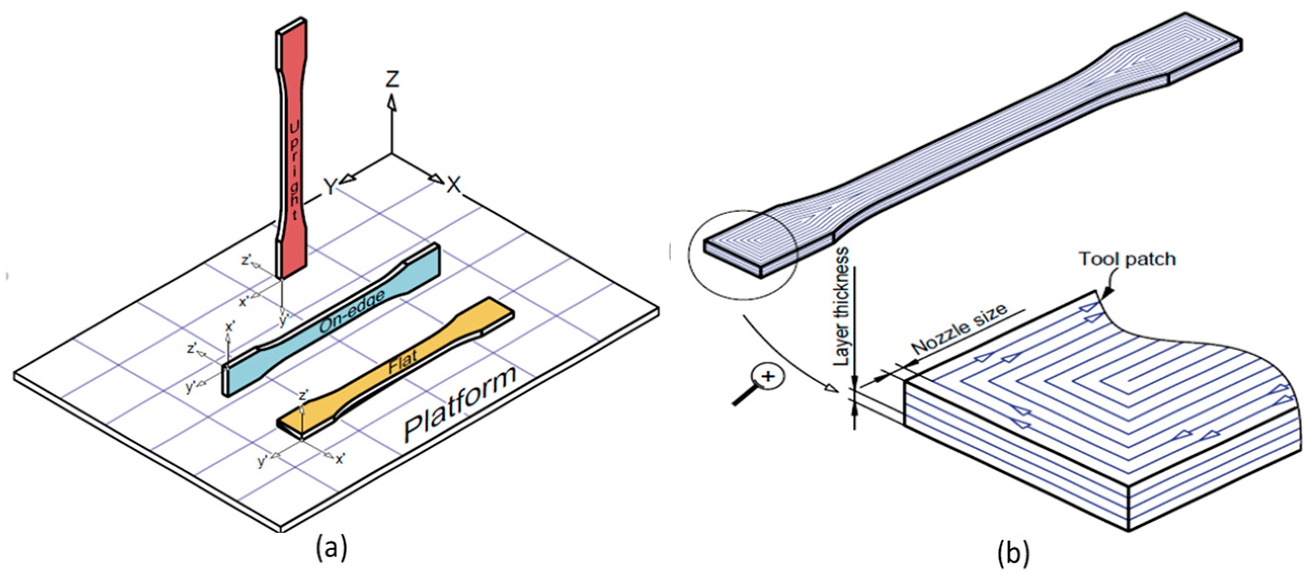
| Material | Process Variables | Physical Setup | Environment | Tensile Strength (MPa) | ||
|---|---|---|---|---|---|---|
| Variables | Set Values of Variables | Significant Variable | ||||
| PLA [62] | Build orientation | Flat, on-edge, upright Layer | Flat, 50 mm/s, and 0.06 mm | Not specific designed | Uncontrolled | 89.1 |
| Layer thickness | 0.06 mm, 0.12 mm, 0.18 mm, 0.24 mm. | |||||
| Feed rate | 20 mm/s, 50 mm/s, 80 mm/s | |||||
| PLA [113] | Strain rate | 2.5 × 10⁻⁴ S−1, 1.25 × 10⁻⁴ S−1 | 2.5 × 10⁻⁴ S−1 | Not specific designed | Uncontrolled | 61.42 |
| Raster angle | 0°, 45°, 90° | 45° | ||||
| Thermal comparison of material in different condition (for crystallinity) | As received filament, Extruded filament, Printed, Printed (annealed) | No significant difference in % crystallinity | ||||
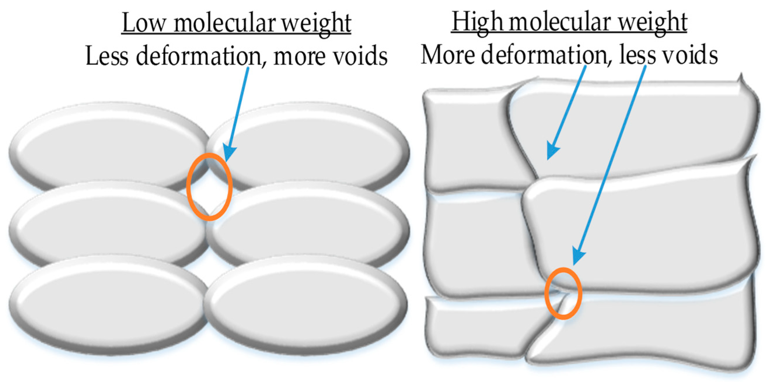
| ABS [7] | Extrusion melt pump pressure | 75 for MG47, 54 for MG94 | Both grades | Not specific designed | Uncontrolled | 34 |
| Two molecular weight grades | MG47 for high MW, MG94 for Low MW | MG47 | ||||
| PEEK [117] | Infill percentage | 20, 50, 100 | Flat and 100% infill | Not specific designed | Uncontrolled | ≈100 |
| Build orientation | Flat, vertical | |||||
| PEEK [121] | Two molecular weight grades | OPTIMA LT3 (low MW),VICTREX 450G (high MW) | VICTREX 450G 14% | Two kinds of setup Syringe based Filament based | Heated plate Lamp heated atmosphere | 75.06 |
| Average Porosity % | 14%, 31% | |||||
| Printing speed | 0 to 120 mm/min | |||||
| Extrusion speed | 0 to 120 mm/min | |||||
| Nozzle diameter | 621.052 µm, 512.03 µm, 407.96 µm | |||||
| PEEK [124] | Printing methods | Line printing, Plane printing | Plane printing | Pellet printer, Glass and steel plate | 98 | |
| PEEK [52] | Build orientation | Flat, vertical, | Flat and 0° | 82.5 | ||
| Raster angle | 0°, 90° | |||||
| PP [1] | Infill percentage | 20%, 60% and 100% | 100% 0° 0.2 | Custom extrusion head. Scrubbed glass bed with alcohol treatment [126] | Uncontrolled | 36 |
| Orientation | 45°, 0°, 90°, crossed 45° (±45°) and crossed 0°–90° | |||||
| Layer thickness | 0.20 and 0.35 | |||||
| Nylon [68] | Build orientation | Flat, on-edge, supright (vertical) | T16 On-edge | Nozzle size T12, T16, T20 | Uncontrolled | ~55 |
| Materials | Process Variables | Physical Setup | Environment | Tensile Strength (MPa) | ||
|---|---|---|---|---|---|---|
| Variables | Set Values of Variables | Significant Variable | ||||
| CF:ABS [155] | Different printers | Makerbot replicator, CubeX, Afinia and Solidoodle 3 | All printers have significance Flat samples have maximum UTS | No | No | 70.69 |
| Build orientation | Flat, Vertical | |||||
| Modified CF:PLA [153] | Pre-printing treatment of CF | Methylene dichloride solution with 8% PLA particles for CF. | Treatment | Customized | No | 91 |
| JF: PLA CF: PLA [154] | Pre-printing heating of continuous CF | 210 °C | Carbon fiber | No separate mechanism for pulling CF. Nichrome wire heater attached with printing head for heating CF. | No | 220 (CF) 60 (JF) |
| Fiber types | Carbon fiber (CF) and Jute fiber (JF) | |||||
| Epoxy: CF [148] | Epoxy pool impregnation of CF | Epoxy pool impregnation | Epoxy pool impregnation | Customized setup | No | 792.8 |
| Printing schemes | Lamina, Honey comb, Grid (not for UTS) | |||||
| Nylon: CF Nylon: Kevlar [156] | Fiber types | Carbon fiber, Kevlar fiber | Nylon: CF 0° | No (Mark One 3D printer) | No | 254.8 (CF), 150.2 (Kevlar) |
| Raster orientation | Orientations for Nylon: Kevlar (0°, ±45°), Nylon:CF (0°) | |||||
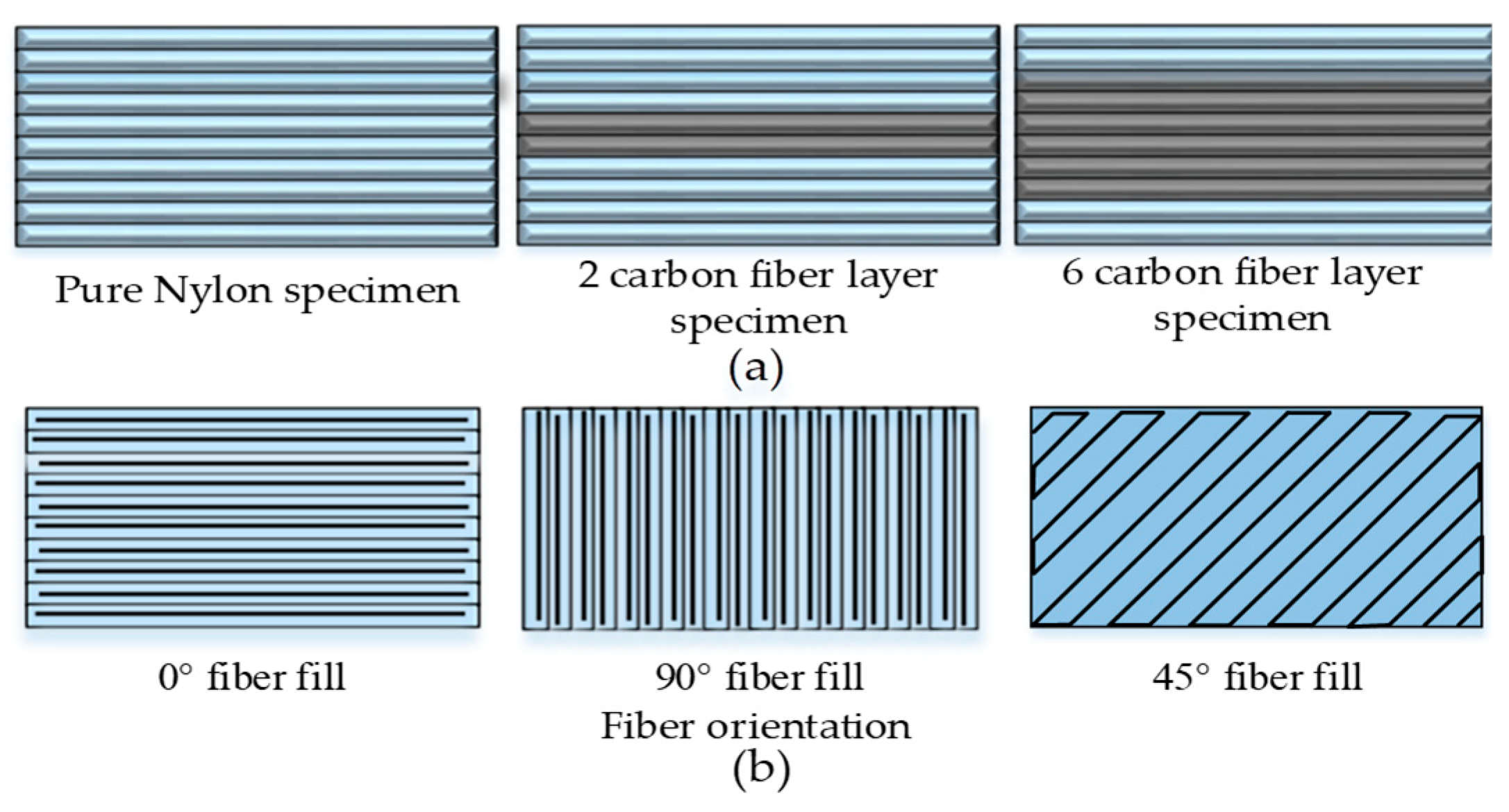
| Nylon:CF [59] | Fiber build strategy with discontinuity in fiber layup each path | Sandwiched Carbon fibers in middle of 10-layer specimen, i.e., 2 layers, and 6 layers | 6 CF layer | No (MarkForged company printer) | No | 464.4 |
| PLA:GF [149] | Pool of PLA | Pool of PLA | Pool of PLA 49.3 0.3 | Customized | No | 479 |
| Fiber composition % | 49.3,46.3,40.18,35.14,28.78,22.74 | |||||
| Extrusion width (mm) | 0.22,0.25, 0.35, 0.4,0.5,0.6,0.8 | |||||
| Nylon: GF Nylon: Kevlar [150] | Fiber composition % | 25% and 50% | 50% Isotropic 0° | Non-commercial two nozzle printing head | No | 283.5 |
| Fill type | Isotropic and Concentric | |||||
| Fill type category 1) Isotropic fill type 2) Concentric fill type | 0°, 45°, and 90° 4 layers 8 layers, and 12 layers | |||||
| Materials | Process Variables | Physical Setup | Environment | Tensile Strength (MPa) | ||
|---|---|---|---|---|---|---|
| Variables | Set Values of Variables | Significant Variable | ||||
| PLA: TCP [157] | Specimen size | 1:1, 1:2 | 1:2 225 C | No | 27.5 | |
| Printing temperature | 215 °C, 225 °C, 235 °C | |||||
| PP:GF [1] | Infill degree % | 20%, 60%, 100% | Infill 100% 0° 0.35 mm | Customized printer | No | 39 |
| Raster orientation | 45°, 0°, 90°, crossed 45° (±45°), 0°–90° | |||||
| Layer thickness | 0.2 mm, 0.35 m | |||||
| ABS: TiO2, ABS: ZnO, ABS: SrTiO3, ABS:AL2O3 [116] | Build orientation | Flat, Vertical | Flat TiO2 | No | No | 32.9 (ABS:TiO2) 20.7 (ZnO) 21.6 (ABS:SrTiO3) 28.8 (ABS:AL2O3) |
| Type of fillers | TiO2, No, SrTiO3, AL2O3 | |||||
| CF:PPS [158] | Raster orientation | 0° (longitudinal), 90° (transverse) | 0° | No | No | 93.22 |
| ABS: OMMT [159] | Laboratory based OMMT (treated) content % | 1%, 3%, 5% | 5% | No | No | 39.48 |
| BioPE: TMP [160] | Laboratory prepared thermos- mechanical pulp fibers (TMP) % | 0%, 10%, 20%, 30% | 30% | No | No | 38.72 |
| ABS: ZnO CABS: ZnO [161] | Type of polymer matrix | ABS, CABS | ABS 100 % Line | Powder ZnO deposition by dispenser during printing | No | 27.5 (ABS:ZnO) 12 (CABS:ZnO) |
| Infill density | 50%, 75%, 100% | |||||
| Infill pattern | Line & rectilinear with 45° raster | |||||
| PPGF: POE-g-MA [129] | Layer thickness | 0.1mm and 0.4 mm | 0.1 mm 20% | Laboratory made PP tape for heating bed | No | 34 |
| POE-G-MA contents % | 10%, 20%, 30% | |||||
| ABS: SCF: SAG [162] | SAG content % | 0%, 1%, 3%, 5%, 7% | 5% | No | No | 73.3 |
| ABS: SCF [55] | Type of reinforcement | Short carbon fibers (SCF), Carbon nanotubes (CNT) | SCF 0° | No | No | 39.05 |
| Raster angle | 45°/-45°, 0° and 90° | |||||
| PLA: CNF [163] | Nozzle geometry | Circle, and square | Square (less voids) 0.5% | No | No | 47 |
| CNF contents % | 0.5%, 0.1% | |||||
| Nylon12:CF [53] | CF contents% | 0%, 2%, 4%, 6%, 8%, 10% | 10% 0° | No | No | 93.8 |
| Raster angle | 0°, 90° | |||||
| Materials | Process Variables | Physical Setup | Environment | Tensile Strength | ||
|---|---|---|---|---|---|---|
| Variables | Set Values of Variables | Significant Variable for Highest Strength | ||||
| ABS:JF [116] | Build orientation | Flat, Vertical | Flat TiO2 | No | No | 24.25 (ABS: JF) |
| Type of fillers | Jute, TiO2, ZnO, SrTiO3, AL2O3 | |||||
| TPU: Wood flour: MDI [164] | Wood flour contents % | 10%, 20%, 30%, 40% | MDI | No | No | 19 |
| Types of modifiers | EPDM-g-MAH, POE-g-MAH, chitosan (cs), polyethylene glycol (PEG), diphenyl methyl propane di-isocyanate (MDI) | |||||
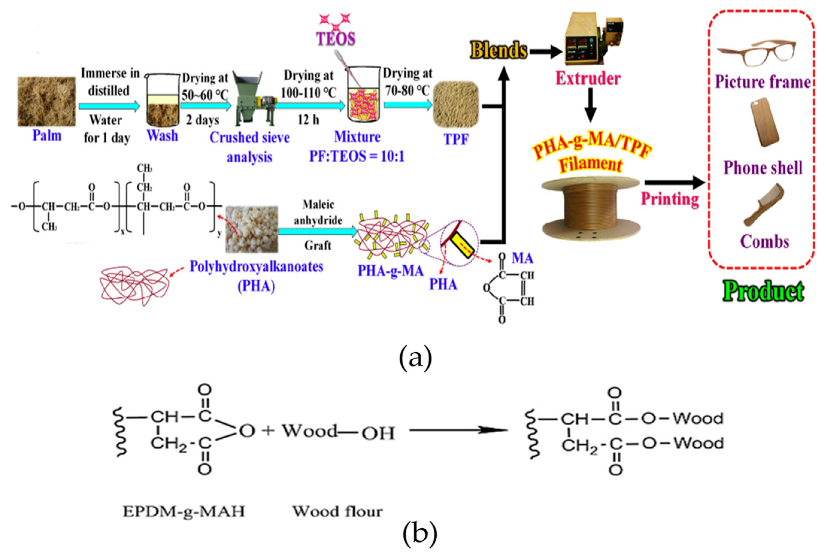
| PHA-g-MAH:PF [4] | Treated palm fiber with Silane coupling agent. | Treated palm fibers (PF) | 20% PHA-g-MAH | No | No | 25 |
| PF composition | 10%, 20%, 30%, 40% | |||||
| Type of polymer matrix | Laboratory prepared PHA-g-MAH, PHA | |||||
| PLA: wood fill fine [165] | Sample width % | 100%, 200%, 300% | 100% 0° | No | No | 31 |
| Raster angle | 0° and 90° (rectilinear infill) | |||||
| ABS: Rice straw [166] | Number of contours | 1, 2 | 2 15% | No | No | 28.89 |
| Rice straw content % | 5%, 10%, 15% | |||||
| PLA: Silk [167] | Types of fibers | Sheep and Silk wool (chemically treated) | Silk 4 100% 0°/90° | No specific physical change. Just provided stay time between layers | No | 24.58 (PLA: Silk) 23.63 (PLA: Sheep wool) |
| Number of laminates | 2, 3, 4 | |||||
| Infill density | 20%, 60%, 100% | |||||
| Raster angle | 0°/90°, 45°/135°, 30°/120° | |||||
| PP: Harakeke PP:Hemp [168] | Types of fibers | Harakeke, hemp | 20% Harakeke | LDPE & PP bed. warpage in glass | No | 24 (PP: Harakeke) 16 (PP: Hemp) |
| Fiber composition | 10%, 20%, 30% | |||||
| PLA: Sugarcane bagasse [169] | Raster angle | 0°/0°, 45°/-45°, 0°/90°, 90°/90° | 45°/45° (only provided tensile strength at 45°/−45°) Sugar cane bagasse fibers | No | No | 57 |
| Sugar cane bagasse fiber composition | 3%, 6%, 9%, 12%, 15% | |||||
| Raw sugarcane bagasse composition | 3%, 6%, 9%, 12%, 15% | |||||
| Materials | Process Variables | Physical Setup | Environment | Tensile Strength (MPa) | ||
|---|---|---|---|---|---|---|
| Variables | Set Values of Variables | Significant Variable | ||||
| PP: SEBS [170] | Composition of PP:SEBS | 20:80, 40:60, 60:40 | 7.5 phr carbon black | PP print bed | No | 18 (7.5 phr) 14 (40PP:60SEBS) |
| Carbon black in 40PP:60SEBS | 0-15 parts per hundred rubber (Phr) | |||||
| Injection molding | 40PP:60SEBS | |||||
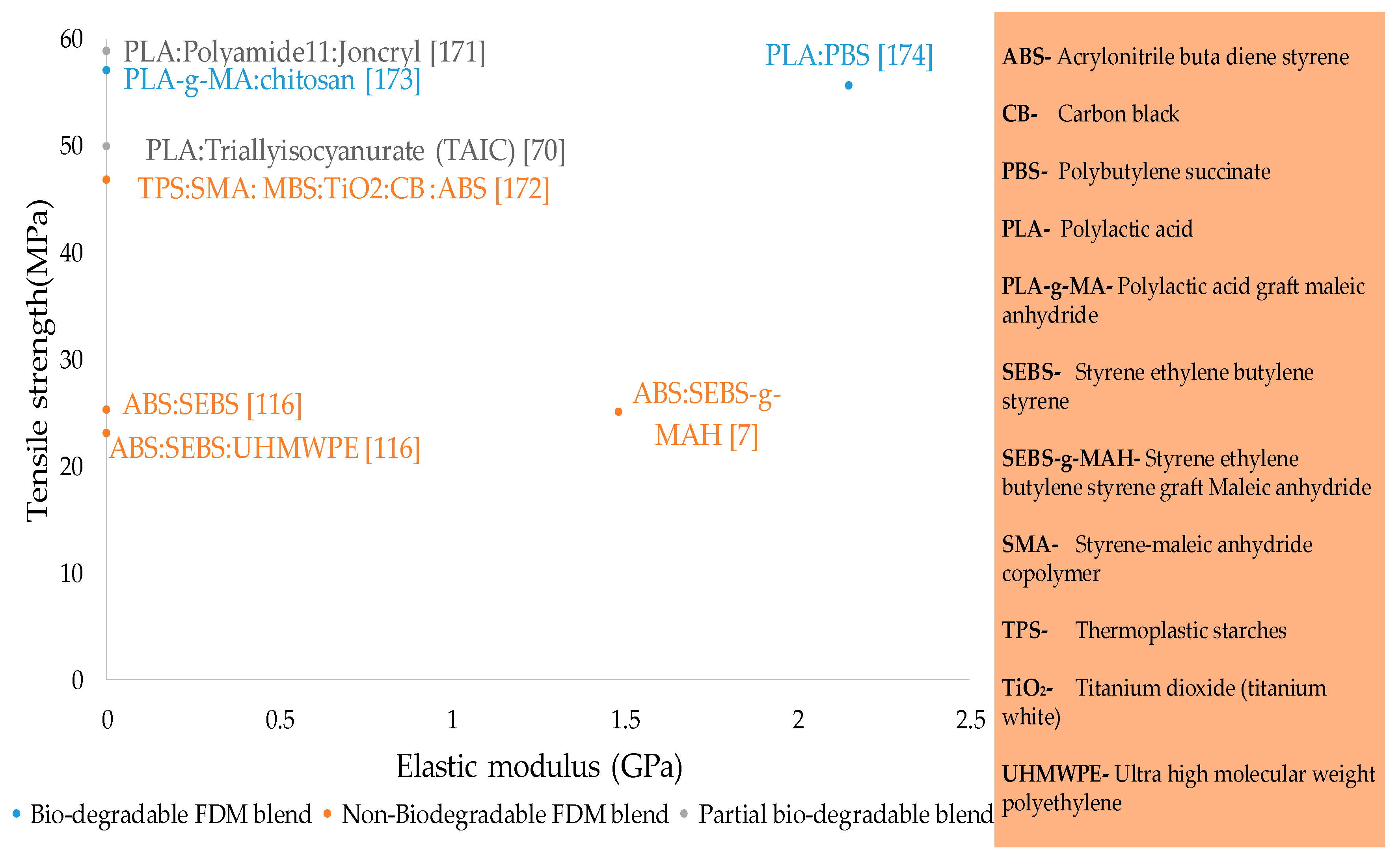
| PLA:PA11:Joncryl [171] | Composition of Joncryl (modified acrylic copolymer with epoxy functions) | 0%, 1%, 2%, 3% | 80:20:2 (PLA:PA11:Joncryl) Injection moulding | No | No | 58.8 |
| Different processes | Injection moulding, FDM | |||||
| ABS:SEBS [116] | Build orientation | Flat, Vertical | Flat TiO2 95:5 90:10:10 | No | No | 25.5 (ABS: SEBS) 23.07 (ABS: UHMWPE: SEBS) |
| Type of fillers | SEBS, UHMWPE: SEBS, Jute, TiO2, ZnO, SrTiO3, AL2O3 | |||||
| Composition | ABS: SEBS (95:5, 80:20) ABS: UHMWPE: SEBS (90:10:10, 75:25:10) | |||||
| TPS:ABS:SMA: MBS:TiO2:CB [172] | Types of polymers Polymers | Styrene maleic anhydride (SMA), methyl- methacrylate butadiene styrene (MBS), TiO2, pigment CB | SMA 30ABS:70%:1SMA:0% TiO2:0%CB | No | No | 46.8 |
| Composition | SMA (1%), MBS (1%, 2%), TiO2 (0%, 5%), CB (0%, 5%), | |||||
| ABS:SEBS-g-MAH [7] | Grades of ABS | MG47, MG940 (w.r.t molecular weight) | MG94 60 mm/s 75%:25% | No | No | 25.09 |
| Feed rate | 30 mm/s and 60 mm/s | |||||
| Composition of ABS: SEBS-g-MAH | 75:25, 50:50, 25:75 One additional for MG94 in 10:90 | |||||
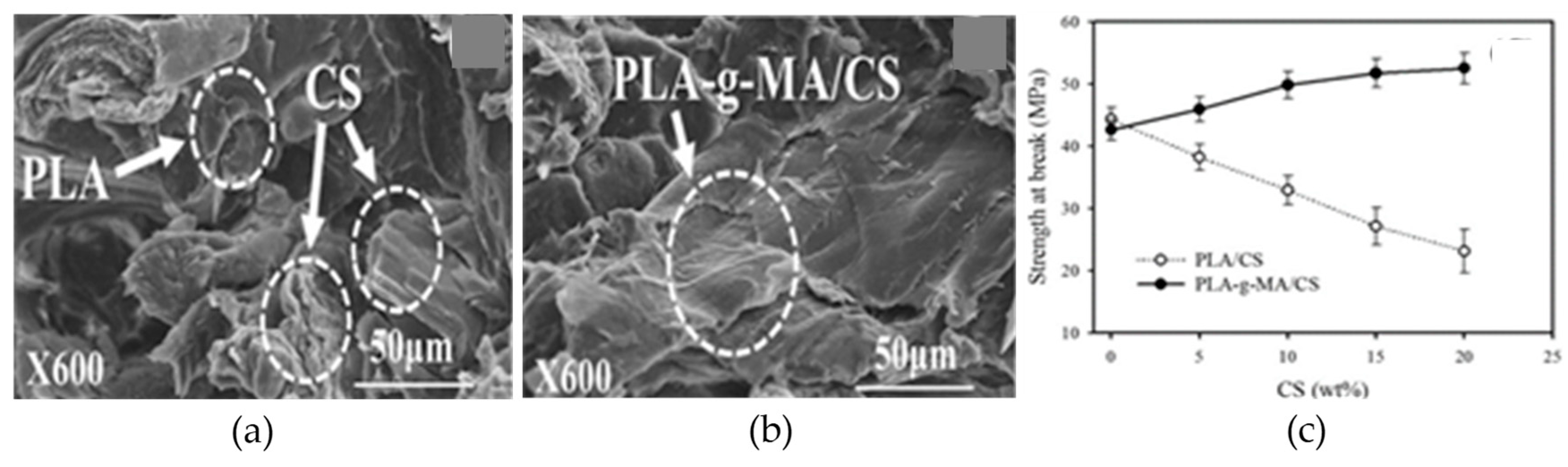
| PLA-g-MA: Chitosan [173] | Types of polymers | PLA, Laboratory prepared PLA-g-MA, | PLA-g-MA 20% | No | No | 57 |
| Chitosan (CS) composition% | 5%, 10%, 15%, 20% | |||||
| PLA-PBS [174] | PBS content % | 20%, 40%, 60%, 80% | 20% | No | No | 55.6 |
| Material | Novel Area/s to Explore |
|---|---|
| PLA | Effects of moisture, thermal and soil degradation on chemical structure and tensile strength |
| ABS | - |
| Nylon | Large-strain behavior to be explored in structural applications |
| PP | Effects of printing in heated environment |
| PC | Effects of post-printing thermal treatment |
| PEEK | - |
| Composites | 1. Printing in heated environment 2. Stability of biodegradable composites against moisture and soil degradation 3. Optimal composite properties considering process (printing) temperature as a variable. |
| Blends | 1. Printing in heated environment 2. Stability of blends against post printing thermal degradation 3. Optimal blend properties considering process (printing) temperature as a variable. |
© 2019 by the authors. Licensee MDPI, Basel, Switzerland. This article is an open access article distributed under the terms and conditions of the Creative Commons Attribution (CC BY) license (http://creativecommons.org/licenses/by/4.0/).
Share and Cite
Harris, M.; Potgieter, J.; Archer, R.; Arif, K.M. Effect of Material and Process Specific Factors on the Strength of Printed Parts in Fused Filament Fabrication: A Review of Recent Developments. Materials 2019, 12, 1664. https://0-doi-org.brum.beds.ac.uk/10.3390/ma12101664
Harris M, Potgieter J, Archer R, Arif KM. Effect of Material and Process Specific Factors on the Strength of Printed Parts in Fused Filament Fabrication: A Review of Recent Developments. Materials. 2019; 12(10):1664. https://0-doi-org.brum.beds.ac.uk/10.3390/ma12101664
Chicago/Turabian StyleHarris, Muhammad, Johan Potgieter, Richard Archer, and Khalid Mahmood Arif. 2019. "Effect of Material and Process Specific Factors on the Strength of Printed Parts in Fused Filament Fabrication: A Review of Recent Developments" Materials 12, no. 10: 1664. https://0-doi-org.brum.beds.ac.uk/10.3390/ma12101664