An Ultrashort Wavelength Multi/Demultiplexer via Rectangular Liquid-Infiltrated Dual-Core Polymer Optical Fiber


1
College of Physics and Optoelectronic Technology, Baoji University of Arts and Sciences, Baoji 721016, China
2
Wireless and Optoelectronics Research and Innovation Centre, Faculty of Computing, Engineering and Science, University of South Wales, Cardiff CF37 1DL, UK
3
Foshan Huikang Optoelectronics Ltd., B block, Sino-European Center, Foshan 528315, China
*
Authors to whom correspondence should be addressed.
Materials 2019, 12(10), 1709; https://0-doi-org.brum.beds.ac.uk/10.3390/ma12101709
Submission received: 15 May 2019
/
Revised: 23 May 2019
/
Accepted: 24 May 2019
/
Published: 26 May 2019
(This article belongs to the Special Issue Novel Optical Fibers, Devices and Applications)
Abstract
:We propose a rectangular liquid-infiltrated dual-core polymer optical fiber (POF) for short-range communication systems by the beam propagation method (BPM). The POF multi/demultiplexer (MUX/DEMUX) at the wavelengths of 0.52/0.65-μm, 0.57/0.65-μm, and 0.52/0.57-μm are devised. The simulation results demonstrate that the ultrashort length of three ultrashort POF couplers are 183.6 μm, 288 μm, and 799.5 μm. Compared with the conventional optical fiber couplers, these results could have significant applications in the miniaturization of optical devices for visible light communication.
1. Introduction
In recent years, with the rapid expansion of optical communication technology, application demands of users for optical transmission networks and systems are growing exponentially. In order to relieve the huge pressure of bandwidth for an optical communication network and system, all kinds of measures have been proposed to increase the capacity of optical networks [1,2,3,4,5,6,7,8]. Wavelength division multiplexing (WDM) is a key technology in advanced optical communication networks. The use of WDM technology not only significantly increases the capacity of the existing optical communication networks without increasing the number of fibers, but also possesses advantages in flexible services, network provision, and network management [9]. The wavelength division multi/demultiplexer (MUX/DEMUX) is an important passive component in the WDM system, which splits/combines lights with different wavelengths into different outputs [10]. All sorts of wavelength MUX/DEMUXs using silica-PLC [2], InGaAs/InP avalanched photodiodes [11], Chirped fiber Bragg grating [12], 2D/3D photonic crystal [13,14], polymer photonic structure [15], and photonic crystal fiber [4] have been demonstrated. At present, the wavelengths of most wavelength division MUX/DEMUXs are located in near-infrared wavelengths [2,4,11,12,13,14,15]. There are very few wavelength division MUX/DEMUXs in the visible wavelengths. Therefore, the design and application of such optical devices in the visible wavelengths are of great significance to develop the visible short-distance communications systems.
Photonic crystal fibers (PCFs) are a special class of optical fibers characterized by a periodical arrangement of microcapillaries that form the fiber’s cladding around a solid or hollow defect core [16,17,18]. Since then, various fiber types such as honeycomb PCF [19], triangular PCF [20], rectangular PCF [21,22,23,24], D-shape PCF [25], side-polished PCF [26], and metal-coated PCF [27] have been demonstrated and applied in the fields of pharmaceutical drug testing, astronomy, communication, and biomedical engineering and sensing [28,29,30,31,32,33,34,35,36,37]. Compared with conventional optical fibers, the unique features of PCFs, such as flexibility of design, endless single-mode wavelength [21], high birefringence [22,23,24], and adjustable dispersion and nonlinearity [38,39], can be obtained by manipulating lattice period, air hole size and shape, refractive index of the materials, and type of lattice. In general, specific categories of PCF include photonic bandgap fibers and index-guiding holey fibers. In this article, we mainly focus on index-guiding holey fibers. The PCFs filled with materials have attracted great interest because PCFs could provide excellent properties by filling different functional materials into the air holes [40,41,42,43]. The PCFs present high-quality microfluidic channels that can be controllably filled with ultrasmall volumes of analytes [44], such as benzene [45,46], glycerin [47], water [48], alcohol [49], and nematic liquid crystal [50]. High birefringence can not only maintain the linear polarization state in the fiber but also increase the difference in coupling length of x-polarized mode and y-polarized mode of PCF. In general, high birefringence of fibers can be gained by introducing asymmetric defect structure such as air holes of different shapes and sizes and asymmetric core [51,52,53]. Another kind of high birefringence structure is the rectangular lattice PCF [21,22,23]. Ferrando et al. found that all polarization guided modes doublets are degenerate in practice in honeycomb and triangular PCF by using precise full-vector calculations, indicating that both geometric structures have negligible anisotropy [18,19,20]. The rectangular lattice is potentially more anisotropic than the triangular and honeycomb lattices. Therefore, based on the above advantages of PCFs, we design a rectangular liquid-filled photonic crystal fiber with high birefringence, which combines the liquid filling, introduction of asymmetric defect structure, and high anisotropy.
Polymer optical fibers (POFs) have a well-established use as a low-cost alternative to silica fiber in short-range communications systems, for example, digital home appliance interfaces, home and car network, and traffic control application, where the attenuation of polymers is very low [54,55]. The cost advantage mainly comes from the ease of installation of the POF fiber, which is simple to cleave and connect and is highly flexible, even with the standard 1mm diameter [56]. A variety of polymers can be used as POFs, such as polymethyl-methacrylate (PMMA), polyethylene, cyclic-olefin copolymer (COC), cyclo-olefin polymer (COP), and Teflon [57,58]. The PMMA has very low attenuation at 520 nm, 570 nm, and 650 nm [59,60,61]. In addition to the capillary stacking technology traditionally used for glass PCF, POFs can be made using techniques such as extrusion, bulk polymerization process, drilling–stretching, and injection molding [62,63,64]. The advantage of such techniques is that different cross-sections can be obtained in the preform, with arbitrary shape and size of the holes [65]. These characteristics of POFs have opened possibilities for the visible wavelength multi/demultiplexers in short-range communication systems.
In this paper, a numerical analysis of a novel rectangular liquid-infiltrated dual-core POF is presented using a vector beam propagation method (BPM) [66,67,68]. The ultrashort POF couplers for 0.52/0.65-μm, 0.57/0.65-μm, and 0.52/0.57-μm wavelength MUX/DEMUX are devised for WDM applications in the visible wavelengths. Besides the great performance, compared with the reported results [25,30,31,32,42,51], another advantage of the proposed structure is that it is simplified so that only the size of filling core and cladding air holes need to be adjusted to achieve the coupler behavior with ultrashort length. Therefore, the proposed couplers possess easy fabrication merit.
2. Design Principle and Theoretical Modeling
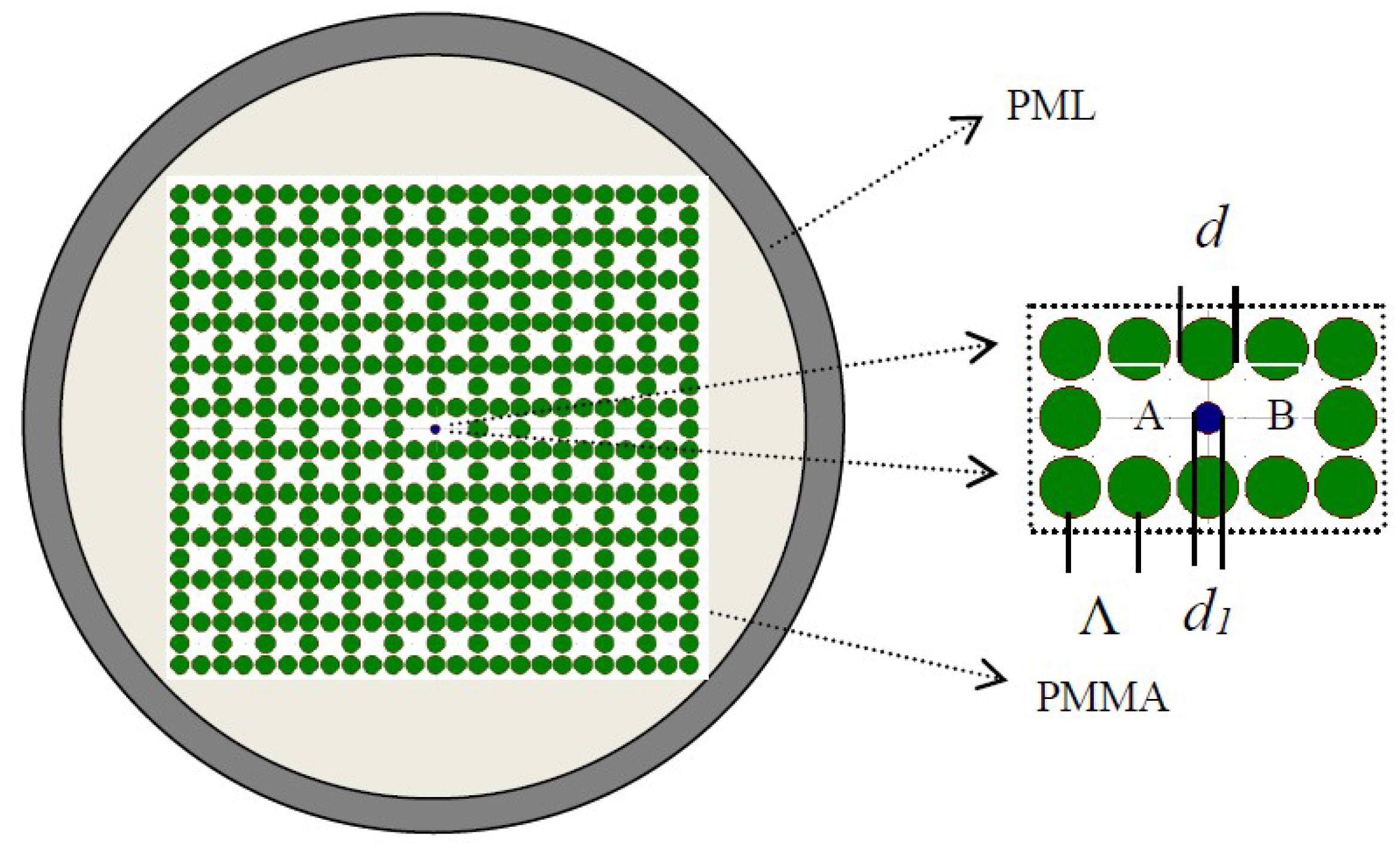
Figure 1 demonstrates a model in which the core region (see the enlarged view of Figure 1) and the cladding region are organized in rectangular formation across the PMMA backdrop. In contrast to a glass optical fiber, the PMMA is a popular material for optical fibers due to the low polymerization temperature, low cost, high transparency, and high mechanical flexibility [57,58]. With the cladding, the green air holes have a diameter of d. In the core region, d1 is the diameter of the blue air hole filled with benzene (n = 1.366). Benzene is a highly toxic carcinogen. How to quickly and easily detect benzene in the environment and food is very important [69]. Therefore, the sensing characteristics of polymer devices based on filled benzene will be considered in future work. The distance of hole to hole can be expressed as period Λ, the air-filling ratio is d/Λ. The refractive index of background material is set as 1.49.
The vector wave equation, which is the basis of BPM [66,67,68], can be expressed by
where . These two equations are known as the Helmholtz equations.
The electric field E(x, y, z) can be separated into two parts: the fast change term of exp(-ikn0z) and the envelope term of ϕ(x, y, z) of slow change in the axial direction, n0 is a refractive index in the cladding. Then, E(x, y, z) is stated as
Substituting Equation (3) in Equation (1) results in
where n is a refractive index in the fiber core.
The relative refractive index is an important parameter to describe the constrained optical field capability of fiber which is expressed as
when , is called the weakly guiding condition.
Assuming the weakly guiding condition, we can approximate . Then Equation (4) can be rewritten as
A similar expression can be written for H. We find that if the fields vary in the transverse direction to propagation. Light propagation in various kinds of waveguides can be analyzed by the above method.
The birefringence is an important index to evaluate the performance of polarization maintaining, which is expressed as [51,52,53,70]
where nx and ny represent the effective refractive index of x-polarization and y-polarization, respectively.
There are four modes of dual-core PCF on the basis of the principle of coupling mode, namely, even-mode of x-polarization, odd-mode of x-polarization, even-mode of y-polarization, odd-mode of y-polarization. The coupling length can be defined as [4]
where denote the effective indexes of even-mode of x-polarization, odd-mode of x-polarization, even-mode of y-polarization, odd-mode of y-polarization, respectively.
When Lλ1 and Lλ2 satisfy the following Equation (9) or (10), a polymer coupler can separate two wavelengths λ1 and λ2 transmitted in a core [4].
or
Assuming that the incident power is emitted to a certain core, the output power of x- or y-polarized light in the core can be expressed [71].
where the transmission distance is denoted by z.
The confinement loss of PCF is calculated from the imaginary part of the effective refractive index, using the following equation [36],
3. Simulated Results and Analysis
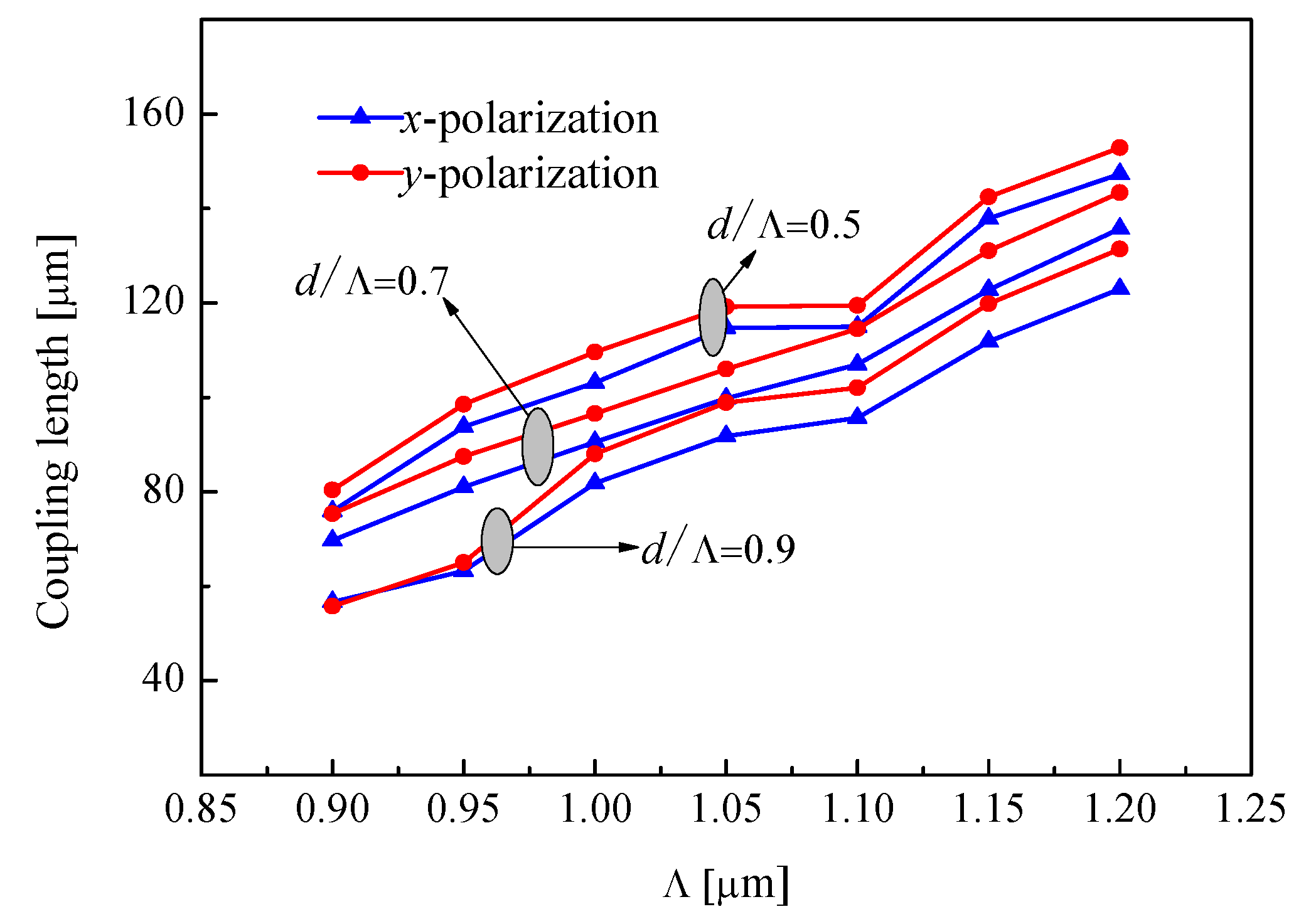
First, we analyze the coupling lengths as a function of period Λ for different air-filling ratio d/Λ, where d1 = 0.4 μm as shown in Figure 2. It is observed that the coupling length is increased when period Λ is increased for a constant air-filling ratio d/Λ. Moreover, the coupling length of y-polarization is higher than the coupling length of x-polarization. Since the x-axis is parallel to the core A and core B, the coupling length of the y-polarization is smaller than that of the x-polarization. Furthermore, we can clearly see that coupling length is decreased when air-filling ratio d/Λ is increased for the same value of period Λ. This is because the restriction of the outer cladding to the light wave is enhanced as the air-filling ratio increases. For the coupler with excellent performance, not only the strong coupling effect between core A and core B but also the good extinction ratio should be considered [4]. Based on the above considerations, we decided to use the y-polarization for the polymer optical fiber couplers.
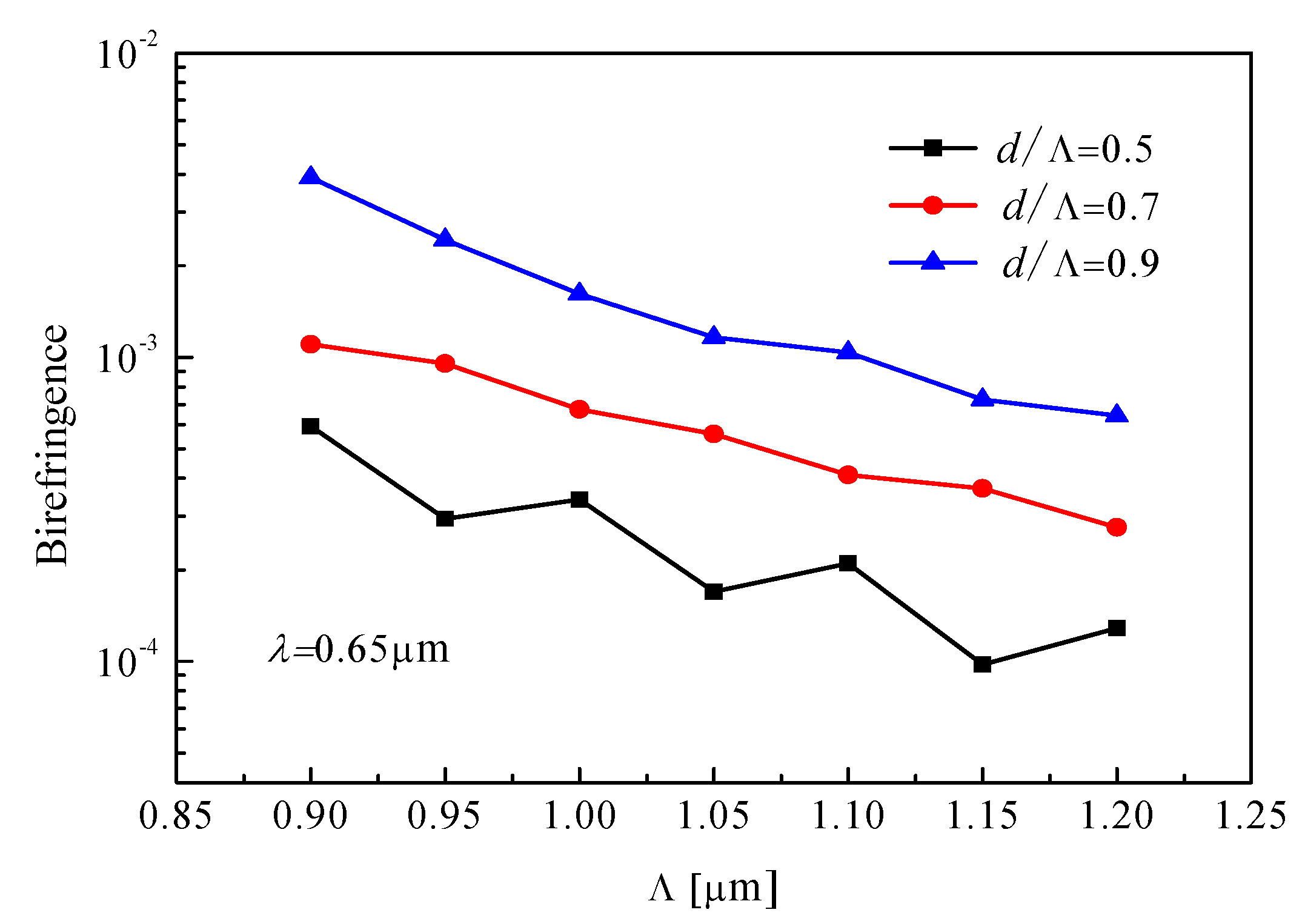
High birefringence can not only maintain the linear polarization state in the fiber but also increase the difference in coupling length of x-polarized mode and y-polarized mode of PCF. Figure 3 shows the birefringence as a function of period Λ. We found that the birefringence of PCF increases with the increase of air-filling ratio d/Λ, which results in stronger coupling strength between the two cores for a shorter coupling length of the polymer optical fiber. Based on the high birefringence of the fiber, we chose the air-filling ratio of 0.9.
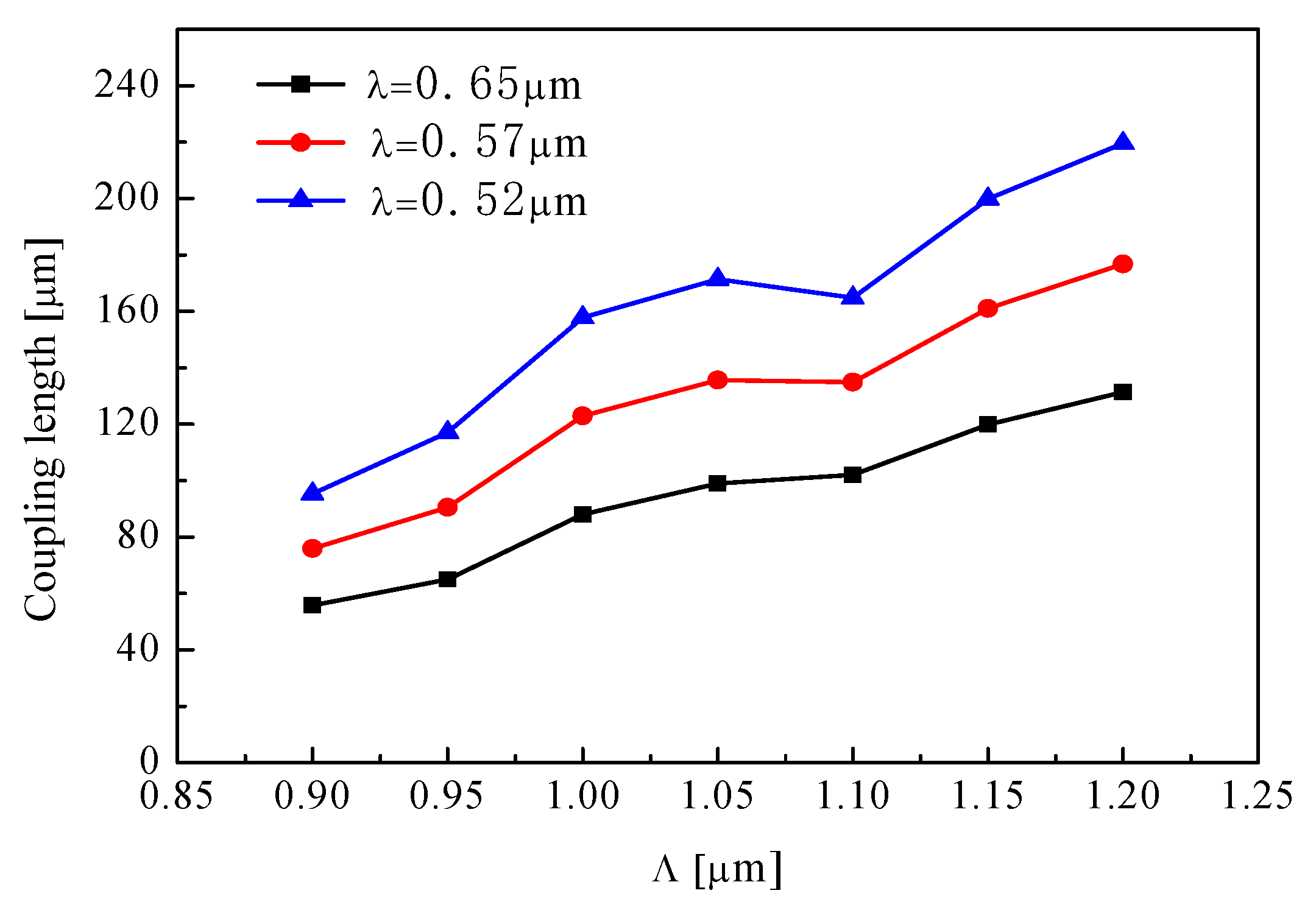
Additionally, when d1 = 0.4 μm, d/Λ = 0.9, the coupling length of y-polarized mode is shown as a function of period Λ in Figure 4, in which it is observed that the coupling length is increased if period Λ is increased. As the period increases, the coupling between the cores becomes weaker. Meanwhile, the coupling length of y-polarization decreases with increasing operating wavelength.
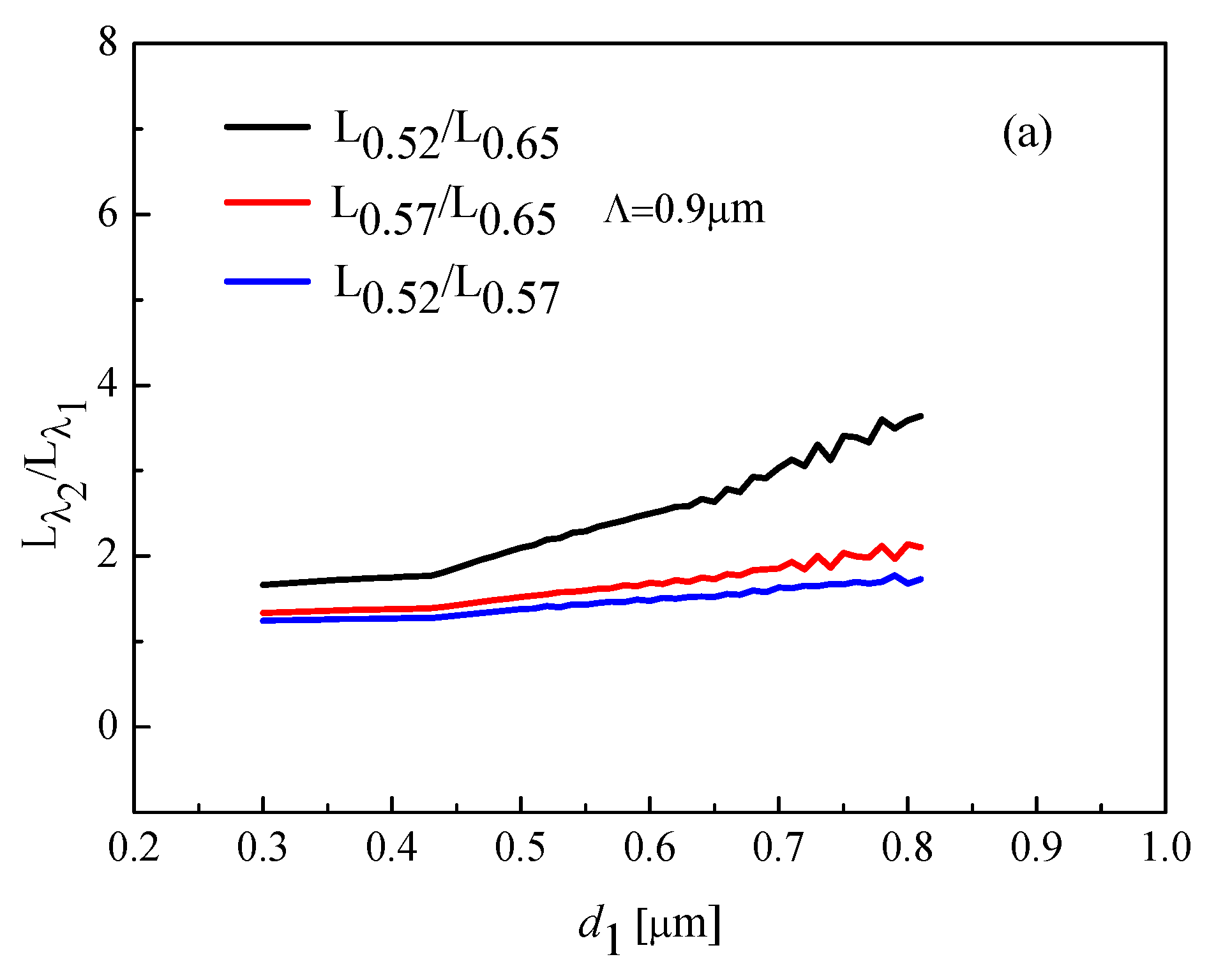
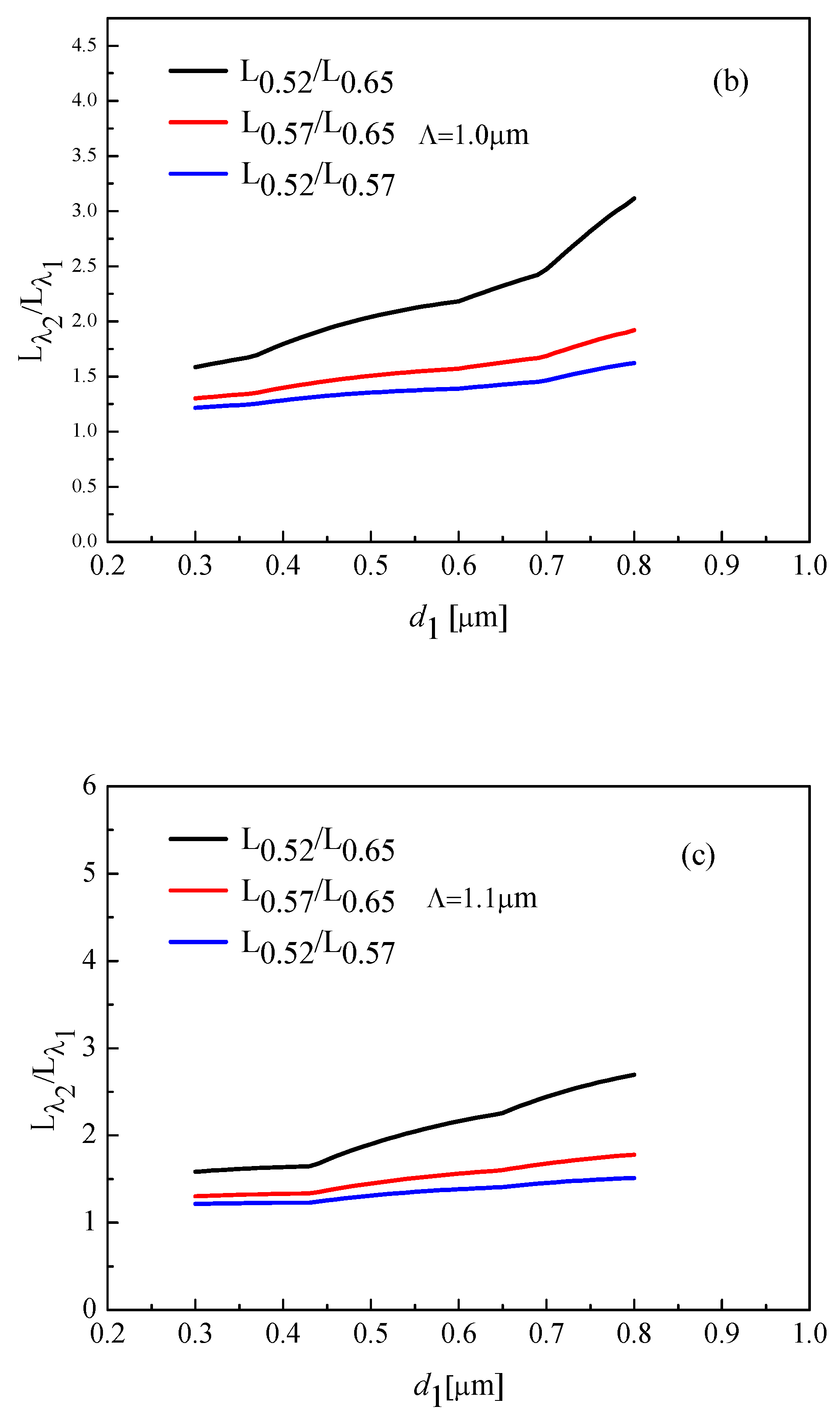
Figure 5 shows coupling ratio Lλ2:Lλ1 by changing d1 from 0.3 to 0.8 for different period Λ and d/Λ = 0.9. The one wavelength is 0.52 μm and 0.57 μm, and the other wavelength is 0.57 μm or 0.65 μm. Therefore, we obtain three couplers, named coupler 1, 2, and 3. In order to obtain an excellent coupling effect, we choose d/Λ = 0.9, Λ = 0.9 μm as the optimal parameters. When d/Λ = 0.9, Λ = 0.9 μm, and d1 = 0.4 μm, L0.57: L0.65 and L0.52:L0.57 for couplers cannot satisfy Equation (9) or (10); L0.52:L0.65 for coupler is 7:4. In order to obtain the ultrashort coupler, we analyze the influence of parameter d1 on the length of the coupler through Figure 5c. Finally, the couplers 1 to 3 are L0.52:L0.65 = 2:1, L0.57:L0.65 = 3:2, and L0.52:L0.57 = 3:2, respectively.
Table 1 shows the optimal parameters of three different wavelength couplers. We can clearly see that the length of coupler 1 is shorter than coupler 2 and 3. This phenomenon is probably related to the difference between the coupling length at 0.65 μm and 0.52 μm. Meanwhile, the length of couplers is much shorter than optical couplers in the References [4,72,73]. The main reasons for the ultrashort coupler are related to the design of fiber structure (rectangular lattice structure), the selection of background materials (PMMA), and the filling of functional materials (benzene).
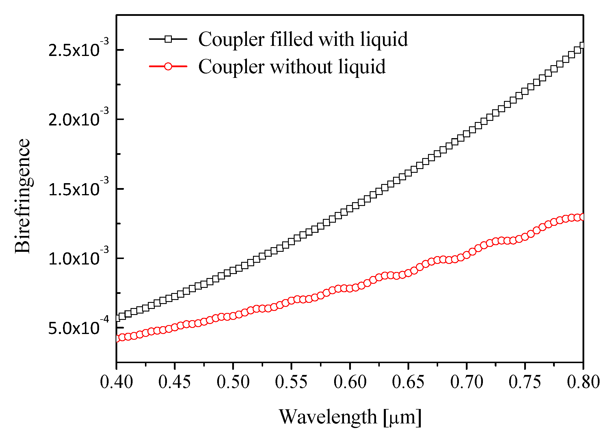
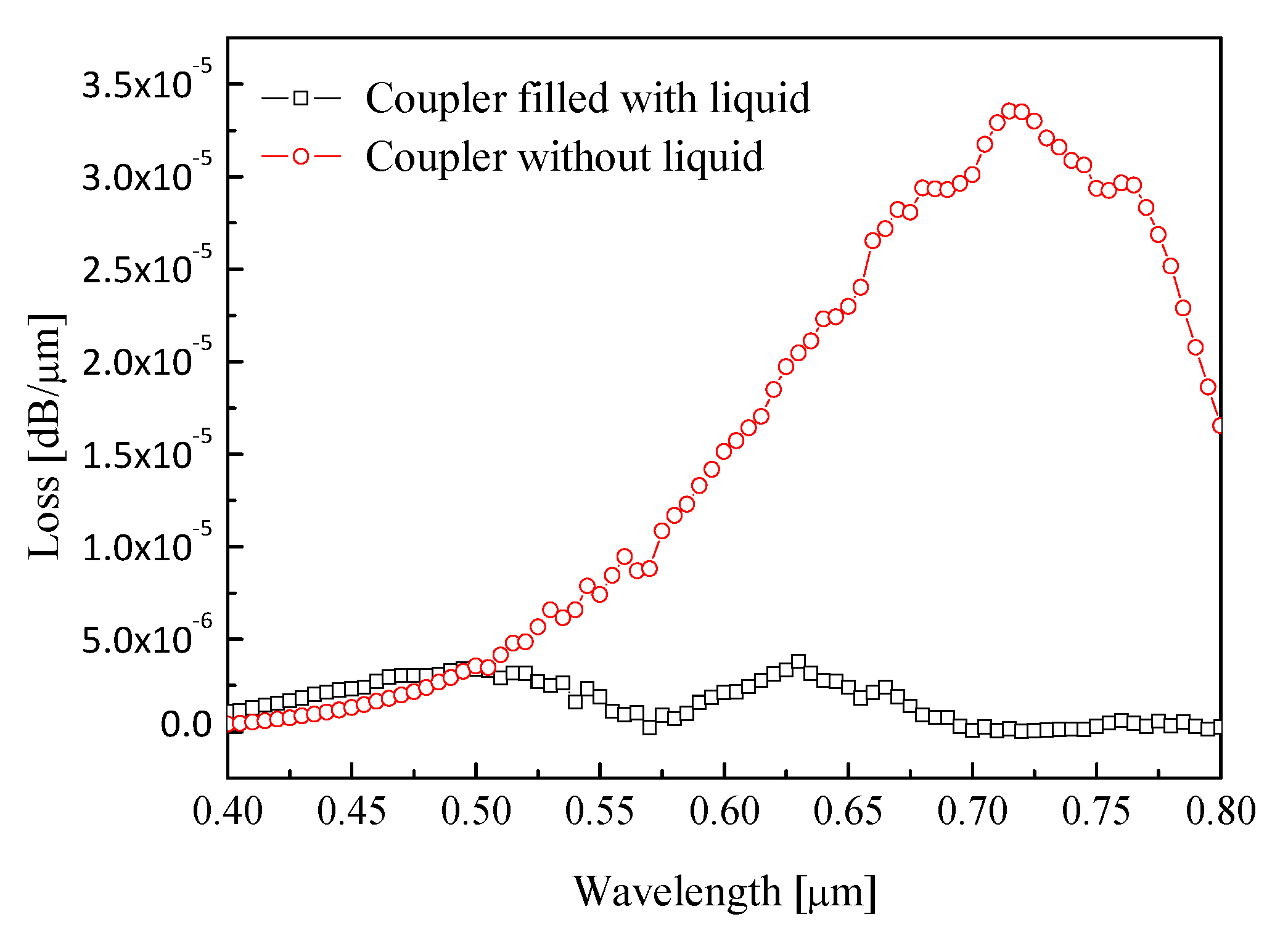
In order to analyze the influence of liquid filling on the transmission performance of couplers, we study the relationship between liquid filling and birefringence and confinement loss of couplers. Figure 6 shows the relationship between the birefringence and filling material for d1 = 0.48 μm, Λ = 0.9 μm, and d/Λ = 0.9. It is observed that birefringence of coupler filled with liquid is higher than birefringence of coupler without liquid. Figure 7 shows the variation of confinement loss with filling material for d1 = 0.48 μm, Λ = 0.9 μm, and d/Λ = 0.9. It can be seen that the confinement loss of the coupler without liquid is higher the confinement loss of the coupler with filled liquid. Therefore, the coupler with filled liquid has lower confinement loss and higher birefringence than the coupler without liquid.
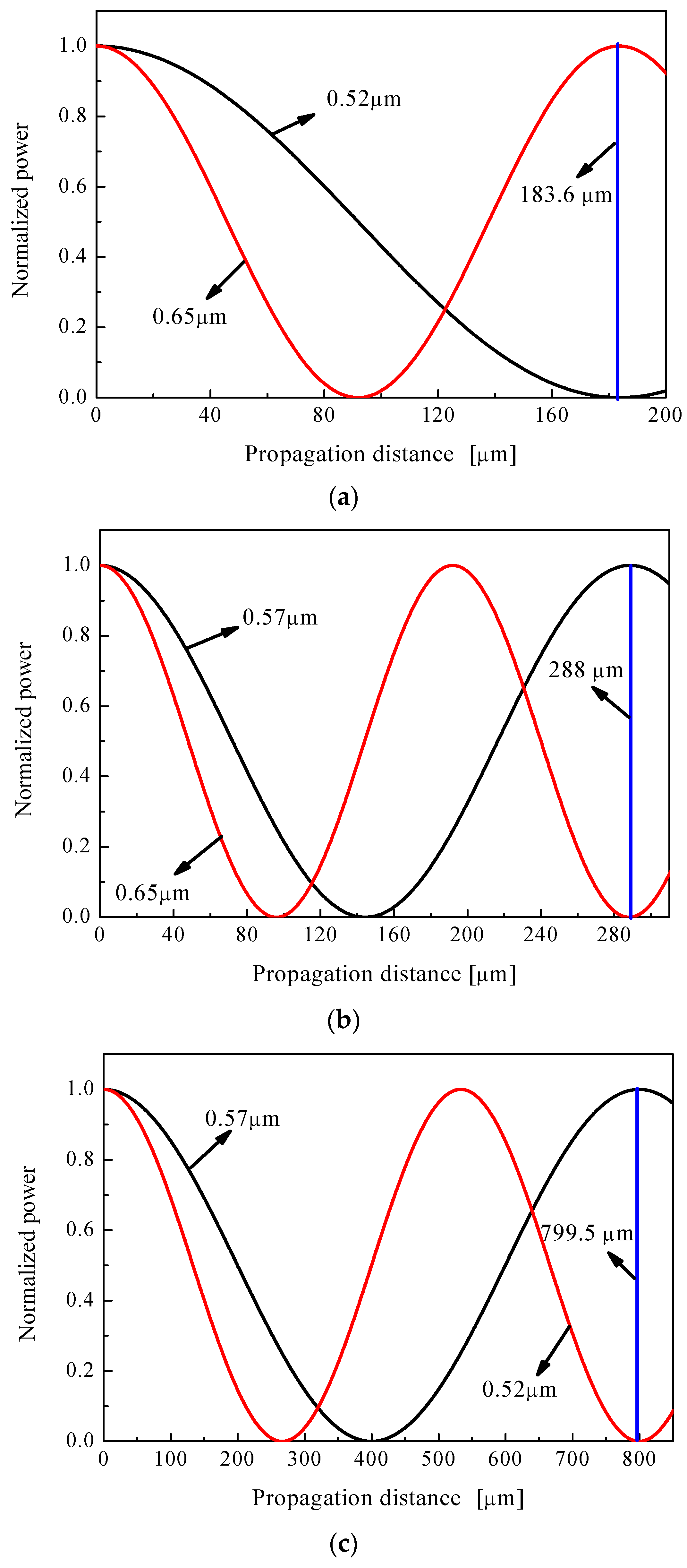
We also demonstrate that three couplers can separate λ1 and λ2 according to the simulation results by BPM. The fundamental modes of y-direction at λ1 and λ2 are imported into the core A or core B in Figure 1. Figure 8 shows the propagation distance dependence of the normalized power. We observed that the separation of two wavelengths of λ1 and λ2 for couplers 1 to 3 are achieved at the distances of 183.6 μm, 288 μm, and 799.5 μm, respectively shown as the blue line in Figure 8. Obviously, the three polymer optical fiber couplers can operate as wavelength MUX/DEMUX at the wavelength of 0.52/0.65-μm, 0.57/0.65-μm, and 0.52/0.57-μm, respectively.
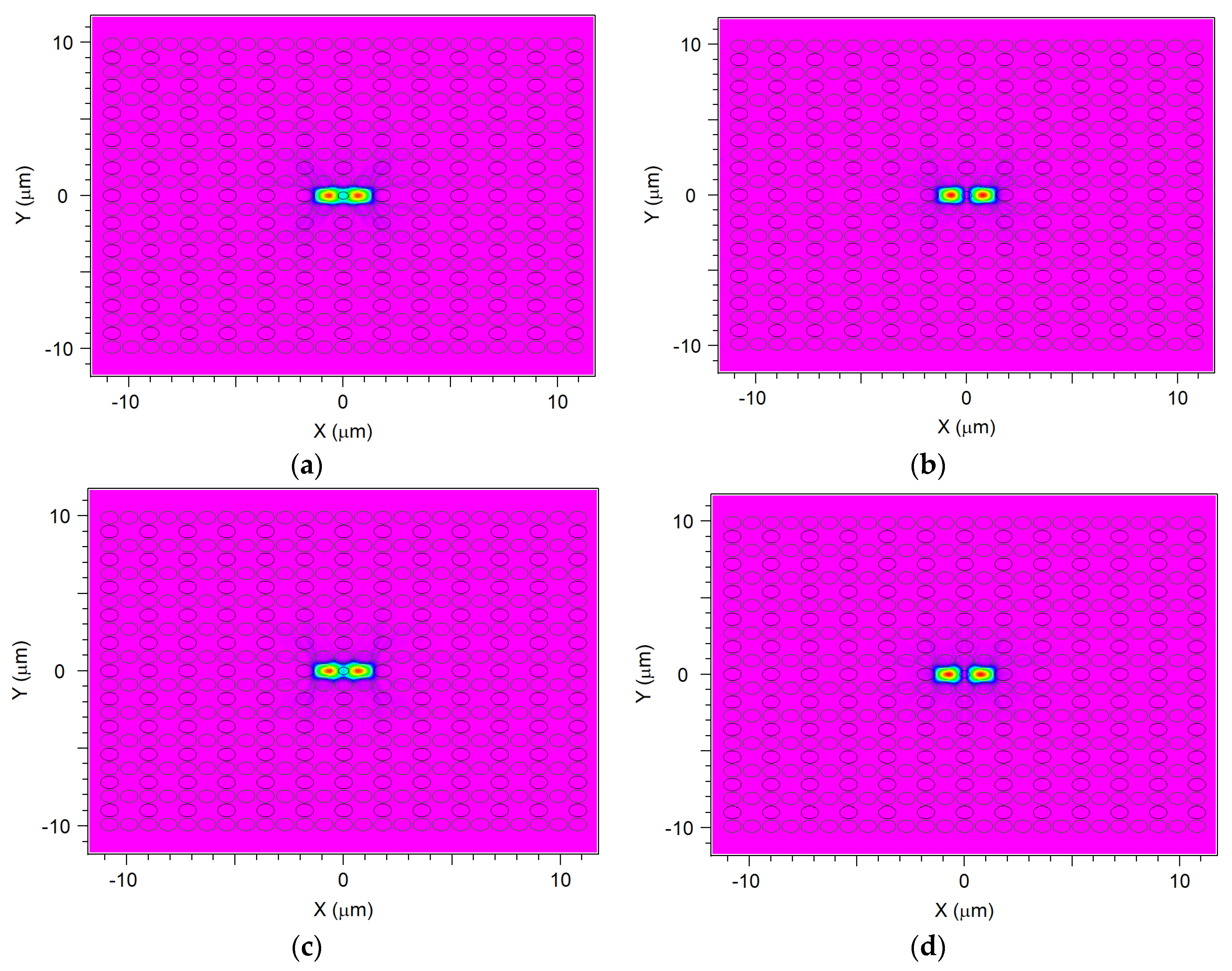
Figure 9 shows odd- and even-mode of x-polarization and y-polarization for the coupler, when d1 = 0.48 μm, Λ = 0.9 μm, and d/Λ = 0.9. It shows the mode-field distribution of the odd- and even- mode in two vertical directions. Moreover, the difference propagation constants and phase difference change of odd- and even-mode in transmission results in a power transfer between two cores [74].
4. Conclusions
Three ultrashort couplers based on rectangular liquid-infiltrated POF have been demonstrated by BPM. The POF couplers for 0.52/0.65-μm, 0.57/0.65-μm, and 0.52/0.57-μm wavelength multi/demultiplexer (MUX/DEMUX) are designed by manipulating structural parameters. The numerical results demonstrate that the lengths of three ultrashort POF couplers are 183.6 μm, 288 μm, and 799.5 μm for the wavelength multiplexing. Compared with the conventional optical fiber couplers, the POF couplers in the visible wavelengths have an ultrashort length, which is important for the application in the miniaturization of optical devices in short-range telecommunication networks [75,76].
Author Contributions
Analysis and writing, Q.X.; project administration, S.L.; methodology, K.L. and N.C.
Funding
This work was funded by the National Natural Science Foundation of China (Grant No. 11547247), Scientific Research Program Funded by Shaanxi Provincial Education Department (Grant No. 18JK0042), and 2015 Foshan City Technology Innovation Group Project (Advanced Solid State Light Source Application and Innovation Team).
Conflicts of Interest
The authors declare no conflicts of interest.
References
- Han, Y.; Hu, G. A novel MUX/DEMUX based on few-mode FBG for mode division multiplexing system. Opt. Commun. 2016, 367, 161–166. [Google Scholar] [CrossRef]
- Kudo, M.; Ohta, S.; Taguchi, E.; Fujisawa, T.; Sakamoto, T.; Matsui, T.; Tsujikawa, K.; Nakajima, K.; Saitoh, K. A proposal of Mach–Zehnder mode/wavelength multi/demultiplexer based on Si/silica hybrid PLC platform. Opt. Commun. 2019, 433, 168–172. [Google Scholar] [CrossRef]
- Tomlinson, W.; Lin, C. Optical wavelength-division multiplexer for the 1–1.4 μm spectral region. Electron. Lett. 1978, 14, 345. [Google Scholar] [CrossRef]
- Saitoh, K.; Sato, Y.; Koshiba, M. Coupling characteristics of dual-core photonic crystal fiber couplers. Opt. Express 2003, 11, 3188. [Google Scholar] [CrossRef]
- Saitoh, K.; Hanzawa, N.; Sakamoto, T.; Fujisawa, T.; Yamashita, Y.; Matsui, T.; Tsujikawa, K.; Nakajima, K. PLC-based mode multi/demultiplexers for mode division multiplexing. Opt. Fiber Technol. 2017, 35, 80–92. [Google Scholar] [CrossRef]
- Ren, F.; Yu, J.; Wang, J. Spatial-mode switchable ring fiber laser based on low mode-crosstalk all-fiber mode MUX/DEMUX. Opt. Fiber Technol. 2018, 101, 21–24. [Google Scholar] [CrossRef]
- Nozhat, N.; Granpayeh, N. Analysis of the plasmonic power splitter and MUX/DEMUX suitable for photonic integrated circuits. Opt. Commun. 2011, 284, 3449–3455. [Google Scholar] [CrossRef]
- Li, X.; Sun, Z.; Yi, W.; Cui, G.; Kong, L.; Yang, X. Computationally efficient coherent detection and parameter estimation algorithm for maneuvering target. Signal Process. 2019, 155, 130–142. [Google Scholar]
- Dutta, A.K.; Dutta, N.K.; Fujiwara, M. WDM Technologies: Passive Optical Components; Academic Press: Cambridge, UK, 2003. [Google Scholar]
- Louro, P.; Vieira, M.; Vieira, M.; Fernandes, M.; Fantoni, A.; Francisco, C.; Barata, M. Optical multiplexer for short range communications. Physica E Low Dimens. Syst. Nanostruct. 2009, 41, 1082–1085. [Google Scholar]
- Lee, M.H.; Ha, C.; Jeong, H.-S.; Kim, D.W.; Lee, S.H.; Lee, M.H.; Kim, K.H. Wavelength-division-multiplexed InGaAs/InP avalanched photodiodes for quantum key distributions. Opt. Commun. 2016, 361, 162–167. [Google Scholar] [CrossRef]
- Romero, R.; Frazăo, O.; Floreanic, F.; Zhang, L.; Marquesa, P.V.S.; Salgado, H.M. Chirped fiber Bragg grating based multiplexer and demultiplexer for DWDM applications. Opt. Lasers Eng. 2005, 43, 987–994. [Google Scholar] [CrossRef]
- Palai, G.; Beura, S.; Gupta, N.; Sinha, R. Optical MUX/DEMUX using 3D photonic crystal structure: A future application of silicon photonics. Optik 2017, 128, 224–227. [Google Scholar] [CrossRef]
- Palai, G. Optimization of optical waveguide for optical DEMUX at optical windows. Optik 2016, 127, 2590–2593. [Google Scholar] [CrossRef]
- Palai, G. Band analysis of polymer photonic structure for MUX/DEMUX application. Optik 2017, 140, 1086–1090. [Google Scholar] [CrossRef]
- Knight, J.C. Photonic crystal fiber. Nature 2003, 424, 847–851. [Google Scholar] [CrossRef] [PubMed]
- Russell, P. Photonic crystal fiber. Science 2003, 299, 358–362. [Google Scholar] [CrossRef]
- Buczynski, R. Photonic crystal fibers. Acta Phys. Polonica A 2004, 106, 147–167. [Google Scholar] [CrossRef]
- Barkou, S.E.; Broeng, J.; Bjarklev, A. Silica-air photonic crystal fiber design that permits waveguiding by a true photonic bandgap effect. Opt. Lett. 1999, 24, 46. [Google Scholar] [CrossRef]
- Ferrando, A.; Silvestre, E.; Miret, J.J.; Andras, P.; Andrãs, M.V. Donor and acceptor guided modes in photonic crystal fibers. Opt. Lett. 2000, 25, 1328. [Google Scholar] [CrossRef]
- Ferrando, A.; Miret, J.J. Sing-polarization sing-mode intraband guidance in supersquare photonic crystals fibers. Appl. Phys. Lett. 2001, 78, 3184–3186. [Google Scholar] [CrossRef]
- Chen, M.; Yu, R.; Zhao, A. Highly birefringence rectangular lattice photonic crystal fiber. J. Opt. A Pure Appl. Opt. 2004, 6, 997–1000. [Google Scholar] [CrossRef]
- Kim, S.; Kee, C.-S.; Lee, C.G. Modified rectangular lattice photonic crystal fibers with high birefringence and negative dispersion. Opt. Express 2009, 17, 7952. [Google Scholar] [CrossRef]
- Yang, T.; Wang, E.; Jiang, H.; Hu, Z.; Xie, K. High birefringence photonic crystal fiber with high nonlinearity and low confinement loss. Opt. Express 2009, 23, 8329–8337. [Google Scholar] [CrossRef] [PubMed]
- Chen, H.; Li, S.; An, G.; Li, J.; Fan, Z.; Han, Y. Polarization splitter based on D-shaped dual-core photonic crystal fibers with gold film. Plasmonics 2015, 10, 57–61. [Google Scholar] [CrossRef]
- Wang, Y. Surface plasmon resonance biosensor based on gold-coated side-polished hexagonal structure photonic crystal fiber. Opt. Express 2017, 25, 20313. [Google Scholar]
- Klantsataya, E.; François, A.; Ebendorff-Heidepriem, H.; Hoffmann, P.; Monro, T.M.; Passaro, V.M. Surface Plasmon Scattering in Exposed Core Optical Fiber for Enhanced Resolution Refractive Index Sensing. Sensors 2015, 15, 25090–25102. [Google Scholar] [CrossRef] [PubMed] [Green Version]
- Hu, D.J.J.; Pui, H. Recent advances in plasmonic photonic crystal fiber: design, fabrication and applications. Adv. Opt. Photonics 2017, 9, 259–314. [Google Scholar] [CrossRef]
- Chiang, J.-S. Analysis of Leaky Modes in Photonic Crystal Fibers Using the Surface Integral Equation Method. Crystals 2018, 8, 177. [Google Scholar] [CrossRef]
- Zhang, L.; Yang, C. A Novel Polarization Splitter Based on the Photonic Crystal Fiber With Nonidentical Dual Cores. IEEE Photonics Technol. Lett. 2004, 16, 1670–1672. [Google Scholar] [CrossRef]
- Yu, Y.; Sun, B. Ultra-Wide-Bandwidth Tunable Magnetic Fluid-Filled Hybrid Connected Dual-Core Photonic Crystal Fiber Mode Converter. Crystals 2018, 8, 95. [Google Scholar] [Green Version]
- Zhang, H.; Zhang, X.; Li, H.; Deng, Y.; Xi, L.; Tang, X.; Zhang, W. The Orbital Angular Momentum Modes Supporting Fibers Based on the Photonic Crystal Fiber Structure. Crystals 2017, 7, 286. [Google Scholar] [CrossRef]
- Islam, M.S.; Sultana, J.; Dinovitser, A.; Faisal, M.; Islam, M.R.; Ng, B.W.-H.; Abbott, D. Zeonex-based asymmetrical terahertz photonic crystal fiber for multichannel communication and polarization maintaining applications. Appl. Opt. 2018, 57, 666–672. [Google Scholar] [CrossRef] [PubMed]
- Vincent Tse, M.; Liu, Z.; Cho, L.; Lu, C.; Wai, P.A.; Tam, H. Super lattice microstructured optical fiber. Materials 2014, 7, 4567–4573. [Google Scholar]
- Jens, K.; Jörg, B.; Katrin, W.; Claudia, A.; Zhiwen, P.; Sonja, U.; Kay, S.; Hartmut, B. Diffusion and Interface Effects during Preparation of All-Solid Microstructured Fibers. Materials 2014, 7, 6879–6892. [Google Scholar] [CrossRef] [Green Version]
- Dumitrache, C.; Rath, J.; Yalin, A.P. High Power Spark Delivery System Using Hollow Core Kagome Lattice Fibers. Materials 2014, 7, 5700–5710. [Google Scholar] [CrossRef] [Green Version]
- Peng, L.; Shi, F.; Zhou, G.; Ge, S.; Hou, Z.; Xia, C. A surface plasmon biosensor based in a D-shaped microstructured optical fiber with rectangular lattice. Opt. Express 2015, 7, 4801309. [Google Scholar]
- Xu, Q.; Miao, R.; Zhang, Y. Highly nonlinear low-dispersion photonic crystal fiber with high birefringence. Opt. Mater. 2012, 35, 217–221. [Google Scholar] [CrossRef]
- Xu, Q. Highly Nonlinear Dispersion-Flattened Photonic Crystal Fiber with High Birefringence. J. Nanoelectron. Optoelectron. 2013, 8, 306–310. [Google Scholar] [CrossRef]
- Liu, Q.; Li, S.-G.; Shi, M. Fiber Sagnac interferometer based on a liquid-filled photonic crystal fiber for temperature sensing. Opt. Commun. 2016, 381, 1–6. [Google Scholar] [CrossRef]
- Sun, B.; Chen, M.; Zhang, Y.; Zhou, J. Polarization-dependent coupling characteristics of metal-wire filled dual-core photonic crystal fiber. Opt. Quantum Electron. 2015, 47, 441–451. [Google Scholar] [CrossRef]
- Fan, Z.; Li, S.; Liu, Q.; Chen, H.; Wang, X. Plasmonic Broadband Polarization Splitter Based on Dual-Core Photonic Crystal Fiber with Elliptical Metallic Nanowires. Plasmonics 2016, 11, 1565–1572. [Google Scholar] [CrossRef]
- Benabid, F.; Knight, J.; Antonopoulos, G.; Russell, P.S.J. Stimulated Raman Scattering in Hydrogen-Filled Hollow-Core Photonic Crystal Fiber. Science 2002, 298, 399–402. [Google Scholar] [CrossRef] [PubMed]
- Wu, D.K.C.; Kuhlmey, B.T.; Eggleton, B.J. Ultrasensitive photonic crystal fiber refractive index sensor. Opt. Lett. 2009, 34, 322. [Google Scholar] [CrossRef]
- Wang, D.; Chen, G.; Wang, L. Thermal tunability of photonic bandgaps in liquid crystal filled polymer photonic crystal fiber. Opt. Fiber Technol. 2016, 29, 95–99. [Google Scholar] [CrossRef]
- Miluski, P.; Kochanowicz, M.; Zmojda, J.; Dorosz, D. 1,4-Bis(2-methylstyryl)benzene doped PMMA fibre for blue range fluorescent applications. Spectrochim. Acta Part A: Mol. Biomol. Spectrosc. 2018, 192, 88–92. [Google Scholar] [CrossRef]
- Xu, Z.; Lim, J.; Hu, D.J.J.; Sun, Q.; Wong, R.Y.-N.; Li, K.; Jiang, M.; Shum, P.P. Investigation of temperature sensing characteristics in selectively infiltrated photonic crystal fiber. Opt. Express 2016, 24, 1699. [Google Scholar] [CrossRef] [PubMed]
- Huang, Y.; Xu, Y.; Yariv, A. Fabrication of functional microstructured optical fibers through a selective-filling technique. Appl. Phys. Lett. 2004, 85, 5182. [Google Scholar] [CrossRef]
- Sultana, J.; Islam, M.S.; Ahmed, K.; Dinovitser, A.; Ng, B.W.-H.; Abbott, D. Terahertz detection of alcohol using a photonic crystal fiber sensor. Appl. Opt. 2018, 57, 2426–2433. [Google Scholar] [CrossRef] [PubMed]
- Haakestad, M.; Alkeskjold, T.; Nielsen, M.; Scolari, L.; Riishede, J.; Engan, H.; Bjarklev, A. Electrically tunable photonic bandgap guidance in a liquid-crystal-filled photonic crystal fiber. IEEE Photonics Technol. Lett. 2005, 17, 819–821. [Google Scholar] [CrossRef]
- Zhang, L.; Yang, C. Polarization splitter based on photonic crystal fibers. Opt. Express 2003, 11, 1015. [Google Scholar] [CrossRef]
- Kim, S.; Kee, C.-S.; Lee, J.; Jung, Y.; Choi, H.-G.; Oh, K. Ultrahigh birefringence of elliptic core fibers with irregular air holes. J. Appl. Phys. 2007, 102, 16101. [Google Scholar] [CrossRef] [Green Version]
- Zhang, L.; Yang, C. Photonic crystal fibers with squeezed hexagonal lattice. Opt. Express 2004, 12, 2371. [Google Scholar] [CrossRef]
- Eijkelenborg, M.A.V.; Large, M.C.J.; Argyros, A.; Zagari, J.; Manos, S.; Issa, N.A.; Bassett, I.; Fleming, S.; McPhedran, R.C.; Sterke, C.M.D.; Nicorovici, N.A.P. Microstructured polymer optical fibre. Opt. Express 2001, 9, 319–327. [Google Scholar] [CrossRef] [PubMed]
- Bunge, C.A.; Beckers, M.; Gries, T. Polymer Optical Fibres; Woodhead Publishing: Cambridge, UK, 2017. [Google Scholar]
- Webb, D.J. Polymer photonic crystal fibre for sensor applications. Opt. Sens. Detection 2010, 7726, 77260Q. [Google Scholar] [Green Version]
- Pakarzadeh, H.; Rezaei, S.; Namroodi, L. Hollow-core photonic crystal fibers for efficient terahertz transmission. Opt. Commun. 2019, 433, 81–88. [Google Scholar] [CrossRef]
- Dash, N.J.; Jha, R. SPR biosensor based on polymer PCF coated with conducting metal oxide. IEEE Photonics Technol. Lett. 2014, 26, 595–598. [Google Scholar] [CrossRef]
- Charas, A.; Menonca, A.L.; Clark, J.; Cabanillas-gonzalez, J.; Bazzana, L.; Nocivelli, A.; Lanzani, G.; Morgado, J. Gain and ultrafast optical switching in PMMA optical fibers and films doped with luminescent conjugated polymers and oligomers. Front. Optoelectron. China 2010, 3, 45–53. [Google Scholar] [CrossRef]
- Fujimoto, S. Recent advances in plastic optical fiber in Japan. SPIE-New Mater. Opt. Waveguides 1987, 799, 139–145. [Google Scholar]
- Loyez, C.; Lethien, C.; Deparis, N.; Vilcot, J.-P.; Kassi, R.; Rolland, N.; Goffin, A.; Rolland, P.A. An Impulse System for 60-GHz Wireless Networks Based on Polymer Optical Fiber. IEEE Photonics Technol. Lett. 2007, 19, 1964–1966. [Google Scholar] [CrossRef]
- Large, M.C.J.; Ponrathnam, S.; Argyros, A.; Pujari, N.S.; Cox, F. Solution doping of microstructured polymer optical fibers. Opt. Express 2004, 12, 1966–1971. [Google Scholar] [CrossRef]
- Wang, J.; Yang, X.; Wang, L. Fabrication and experimental observation of monolithic multi-air-core fiber array for image transmission. Opt. Express 2008, 16, 7703. [Google Scholar] [CrossRef]
- Zhang, Y.; Li, K.; Wang, L.; Ren, L.; Zhao, W.; Miao, R.; Large, M.C.J.; Van Eijkelenborg, M.A. Casting preforms for microstructured polymer optical fibre fabrication. Opt. Express 2006, 14, 5541. [Google Scholar] [CrossRef] [PubMed]
- Van Eijkelenborg, M.A.; Argyros, A.; Barton, G.; Bassett, I.M.; Fellew, M.; Henry, G.; Issa, N.A.; Large, M.C.; Manos, S.; Padden, W.; et al. Recent progress in microstructured polymer optical fibre fabrication and characterisation. Opt. Fiber Technol. 2003, 9, 199–209. [Google Scholar] [CrossRef]
- Feit, M.D.; Fleck Jr, J.A. Light propagation in graded-index optical fiber. Appl. Opt. 1978, 24, 3990–3998. [Google Scholar] [CrossRef] [PubMed]
- Xiao, J.; Sun, X. A Modified full-vectorial finite-difference beam propagation method based on H-fields for optical waveguides with step-index profiles. Opt. Commun. 2006, 266, 505–511. [Google Scholar] [CrossRef]
- Xie, K.; Boardman, A.D.; Xie, M.; Yang, Y.J.; Jiang, H.M.; Yang, H.J.; Wen, G.J.; Li, J.; Chen, K.; Chen, F.S. A Simulation of longitudinally magnetized three-dimensional magneto-optical devices by a full-vectorial beam propagation method. Opt. Commun. 2008, 281, 3275–3285. [Google Scholar] [CrossRef]
- Bard, D.; Kihal, W.; Schillinger, C.; Fermanian, C.; Segala, C.; Glorion, S.; Arveiler, D.; Weber, C. Traffic-related air pollution and the onset of myocardial infarction: disclosing benzene as a trigger? A small-area case-crossover study. PLoS ONE 2014, 9, e100307. [Google Scholar] [CrossRef]
- Xu, Q.; Miao, R.; Zhang, Y. High birefringence low-dispersion of nonlinear photonic crystal fiber. Optik 2013, 124, 2269–2272. [Google Scholar]
- Eisenmann, M.; Weidel, E. Single-mode fused biconical coupler optimized for polarization beam splitting. J. Lightwave Technol. 1991, 9, 853–858. [Google Scholar] [CrossRef]
- Li, X.-Y.; Sun, B.; Yu, Y.-Y.; He, K.-P. Bending dual-core photonic crystal fiber coupler. Optik 2014, 125, 6478–6482. [Google Scholar] [CrossRef]
- Wang, E.; Cheng, Q.; Li, J.; Zhang, C. Tunable wavelength division multiplexer based on thermal liquid-filled photonic crystal fiber. Optik 2018, 160, 13–16. [Google Scholar] [CrossRef]
- Zi, J.; Li, S.; An, G.; Fan, Z. Short-length polarization splitter based on dual-core photonic crystal fiber with hexagonal lattice. Opt. Commun. 2016, 363, 80–84. [Google Scholar] [CrossRef]
- Kruglov, R.; Vinogradov, J.; Ziemann, O.; Loquai, S.; Bunge, C.-A. 10.7-Gb/s Discrete Multitone Transmission Over 50-m SI-POF Based on WDM Technology. IEEE Photonics Technol. Lett. 2012, 24, 1632–1634. [Google Scholar] [CrossRef]
- Joncic, M.; Kruglov, R.; Haupt, M.; Caspary, R.; Vinogradov, J.; Fischer, U.H.P. Four-channel WDM transmission over 50-m SI-POF at 14.77 Gb/s using DMT modulation. IEEE Photonics Technol. Lett. 2014, 26, 1328–1331. [Google Scholar] [CrossRef]
Figure 1.
Cross-section of the proposed polymer optical fiber. The enlarged view of the core region is shown in the illustration.
Figure 1.
Cross-section of the proposed polymer optical fiber. The enlarged view of the core region is shown in the illustration.

Figure 2.
Period Λ dependence of the coupling lengths for different air-filling ratio d/Λ.

Figure 3.
Period Λ dependence of the birefringence for different air-filling ratio d/Λ.

Figure 4.
Period Λ dependence of the coupling length for different wavelength.

Figure 5.
d1 dependence of the different coupling ratios, (a) when d/Λ = 0.9, (b) when d/Λ = 1.0, and (c) when d/Λ = 1.1.
Figure 5.
d1 dependence of the different coupling ratios, (a) when d/Λ = 0.9, (b) when d/Λ = 1.0, and (c) when d/Λ = 1.1.


Figure 6.
Birefringence as a function of filling material.

Figure 7.
Confinement loss as a function of filling material.

Figure 8.
The propagation distance dependence of the normalized power for the three couplers, (a) at the wavelength of 0.52/0.65-μm, (b) at the wavelength of 0.57/0.65-μm, and (c) at the wavelength of 0.52/0.57-μm.
Figure 8.
The propagation distance dependence of the normalized power for the three couplers, (a) at the wavelength of 0.52/0.65-μm, (b) at the wavelength of 0.57/0.65-μm, and (c) at the wavelength of 0.52/0.57-μm.

Figure 9.
(a) Even-mode of x-direction, (b) odd-mode of x-direction, (c) even-mode of y-direction, (d) odd-mode of y-direction for coupler.
Figure 9.
(a) Even-mode of x-direction, (b) odd-mode of x-direction, (c) even-mode of y-direction, (d) odd-mode of y-direction for coupler.


Table 1.
Design parameters of the polymer optical fiber couplers.
| Parameters | Couplers | |||||
|---|---|---|---|---|---|---|
| 1 | 2 | 3 | 4 (Reference [72]) | 5 (Reference [73]) | 6 (Reference [4]) | |
| λ1 [μm] | 0.65 | 0.65 | 0.57 | 1.55 | 1.55 | 1.55 |
| λ2 [μm] | 0.52 | 0.57 | 0.52 | 0.85/0.98/1.3/1.48 | 0.98/1.31 | 0.85/0.98/1.3/1.48 |
| Λ [μm] | 0.9 | 0.9 | 0.9 | - | - | - |
| d/Λ | 0.9 | 0.9 | 0.9 | - | - | - |
| d1 [μm] | 0.48/0.4 | 0.49 | 0.62 | - | - | - |
| Length [μm] | 183.6/452.3 | 288 | 799.5 | 4168 | 2475 | 1178/418/712/2284 |
© 2019 by the authors. Licensee MDPI, Basel, Switzerland. This article is an open access article distributed under the terms and conditions of the Creative Commons Attribution (CC BY) license (http://creativecommons.org/licenses/by/4.0/).
Share and Cite
MDPI and ACS Style
Xu, Q.; Li, K.; Copner, N.; Lin, S. An Ultrashort Wavelength Multi/Demultiplexer via Rectangular Liquid-Infiltrated Dual-Core Polymer Optical Fiber. Materials 2019, 12, 1709. https://0-doi-org.brum.beds.ac.uk/10.3390/ma12101709
AMA Style
Xu Q, Li K, Copner N, Lin S. An Ultrashort Wavelength Multi/Demultiplexer via Rectangular Liquid-Infiltrated Dual-Core Polymer Optical Fiber. Materials. 2019; 12(10):1709. https://0-doi-org.brum.beds.ac.uk/10.3390/ma12101709
Chicago/Turabian StyleXu, Qiang, Kang Li, Nigel Copner, and Shebao Lin. 2019. "An Ultrashort Wavelength Multi/Demultiplexer via Rectangular Liquid-Infiltrated Dual-Core Polymer Optical Fiber" Materials 12, no. 10: 1709. https://0-doi-org.brum.beds.ac.uk/10.3390/ma12101709
Note that from the first issue of 2016, this journal uses article numbers instead of page numbers. See further details here.