Effect of CeO2 on Impact Toughness and Corrosion Resistance of WC Reinforced Al-Based Coating by Laser Cladding

1
College of Mechatronic Engineering, North University of China, Taiyuan 030051, China
2
School of Mechatronical Engineering, Beijing Institute of Technology, Beijing 100081, China
*
Author to whom correspondence should be addressed.
Materials 2019, 12(18), 2901; https://0-doi-org.brum.beds.ac.uk/10.3390/ma12182901
Submission received: 9 August 2019
/
Revised: 2 September 2019
/
Accepted: 6 September 2019
/
Published: 8 September 2019
(This article belongs to the Special Issue Advances in Laser Processing)
Abstract
:WC reinforced Al-based coating with added CeO2 was prepared on the surface of S420 steel by laser cladding. The microstructure and structure of the coatings were analyzed by scanning electron microscope, X-ray diffractometer and optical profiler. The mechanical properties and corrosion properties of the coatings were studied by microhardness tester, friction and wear tester, Charpy impact tester, and electrochemical workstation. The results show that the coating is mainly composed of Al-phase, continuous-phase, and hard reinforced-phase WC, and the coating and substrate show good metallurgical bonding. When the content of CeO2 is 1%, the fine grain strengthening effect is obvious, and the impact toughness of the coating is obviously improved. Appropriate amount of rare earth CeO2 can significantly improve the hardness of the coating. When the content of CeO2 is more than 1%, the wear resistance of the coating decreases. The coating prepared with different CeO2 content has higher impedance and corrosion resistance than that of the substrate. At 1% CeO2 content, the coating has the best corrosion resistance.
1. Introduction
Offshore platform is a tool for human beings to develop marine resources, which is used in severe marine working environments such as waves, tide, storm and cold current ice. These environments determine that offshore platform steel must have high strength, toughness, corrosion resistance, fatigue resistance, and layered tear resistance [1,2,3]. At present, S420 steel has been widely used in the construction of offshore oil platform. As national offshore oil and gas development is gradually moving towards the deep water area, the thickness, quality, and construction difficulty of the plate used in offshore engineering structural steel are increasing [4,5,6,7]. Simultaneously, the marine deep water area environment is complex, and usual iron and steel materials have been unable to meet the needs of use [8,9]. Laser cladding ceramic particle reinforced metal-based composite coating has the advantages of high strength, high hardness, high wear resistance, and high corrosion resistance, which is an effective way to solve the failure of materials in complex environment [10,11,12]. For example, Ye et al. have prepared V8C7 reinforced Fe based composite coatings with different volume fraction. With the increase of volume fraction of reinforced-phase, the hardness of the composite coating increased, while the impact toughness decreased from 8.1 J/cm2 to 4.7 J/cm2. When the volume fraction of the reinforced phase is less than 24%, the wear resistance of the coating increases with the increase of V8C7 content, and when the volume fraction is more than 24%, the wear resistance decreases due to the crushing of particles and the generation of microcracks [13].
There are great differences in physical and chemical properties between ceramic particles and matrix materials, such as thermal expansion coefficient, interfacial strength, brittleness of reaction products, etc., which may lead to the plasticity and toughness of the composite coating lower than that of the matrix material. Under the condition of impact load. Composites are prone to fracture and early failure, thus decreasing corrosion resistance in the marine environment, which greatly limits the application and development of matrix materials [14,15]. Rare earth elements can improve the microstructure and properties of laser cladding coating, increase the compactness of coating structure, reduce the coefficient of thermal expansion between coating and substrate, and reduce the thermal stress, impurities, and cracks in the coating [16]. Zhang et al. studied the effect of CeO2 on the microstructure and corrosion resistance of TiC-VC reinforced Fe-based laser cladding coating. With increasing CeO2 addition, the number of flake pearlite increased, the amount of retained austenite decreased, and the corrosion resistance of cladding coating increased at first and then decreased. When 0.5 wt.% CeO2 is added, the corrosion resistance of the coating is the best [17]. Sun et al. prepared (Ti, Nb)C/Ni coatings with different amount of CeO2. The results showed that the size of (Ti, Nb)C particles was suppressed by rare earth element Ce, which is prone to accumulate at the interface of grain boundary or crystalline phases. The unmelted CeO2 can also be used as the basis for heterogeneous nucleation of (Ti,Nb)C, Cr23C6, and Cr7C3 particles. In addition, with increasing CeO2 content, the tensile properties of the coating were improved, and the fracture behavior changed from quasi-cleavage fracture to brittle fracture [18].
From the literature review, the ceramic particle reinforced metal-based composite coating can significantly improve the hardness of the coating and improve the corrosion resistance to a certain extent. However, with the increase of the volume fraction of ceramic particles, the impact toughness of the composite coating decreases seriously, resulting in particle breakage or matrix cracking in some environments, and the corrosion resistance decreases instead. Therefore, improving the impact toughness of composite coating without losing their corrosion resistance has become the research focus of particle reinforced metal-based materials [19,20].
In this work, we mainly use the idea of rare earth purification to prepare particle reinforced metal-based composite coatings with different rare earth content. The microstructure, impact toughness and corrosion resistance of the composite coating were studied systematically by scanning electron microscope, X-ray diffractometer, Charpy impact tester, and electrochemical workstation, and the action mechanism of rare earth was analyzed. It provides an experimental basis for the effective combination of impact toughness and corrosion resistance of ceramic particles reinforced metal-based composites.
2. Experimental
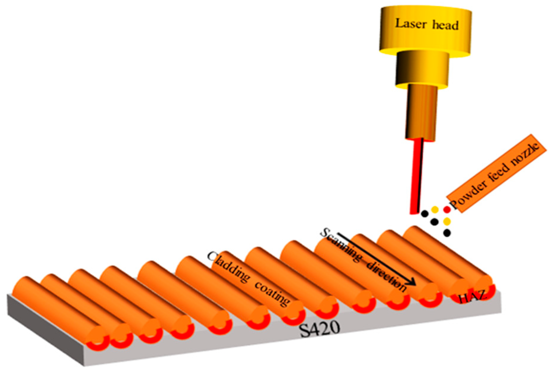
The experimental material was European standard S420 structural steel (HBIS WU Steel, Shijiazhuang, China). Table 1 shows the chemical composition of S420 steel. The size of the matrix material is 60 mm × 30 mm × 3 mm. The surface is mechanically polished and washed repeatedly with acetone. The cladding powder material is Al powder, Ni powder, and WC powder, which are mixed according to the mass ratio of 6:1:2, the particle size of the mixed powder is 45–100 μm. Rare earth CeO2 was added at the mass ratio of 0%, 1%, 1.5%, and 2%, respectively. It was fully mixed and ground by ball mill, and then put into the drying box at 60 °C for 30 min. Each group of powder samples was tested by laser cladding three times. According to the macroscopic test results of the three cladding samples, the samples with better cladding quality were selected to test the microstructure and properties. The laser cladding test is completed by YSL-4000 optical fiber laser processing system using synchronous powder-feeding cladding. Figure 1 shows the principle of laser cladding process. The laser power is 1300 W, the scanning speed is 0.5 m/min, the powder feeding rate is 8 g/min, and the spot diameter is 3 mm. The laser cladding adopts the method of multichannel and multilayer lap, and the lap rate is 40%. After the cladding is completed, the sample is cut into the size of 10 mm × 10 mm × 3 mm by wire cutting. After the completion of the cladding experiment, the surface of the cladding coating was polished step by step with water-scrubbed paper, and the finished sample was mechanically polished with Al2O3 polishing solution and de-oiled by acetone ultrasonic.
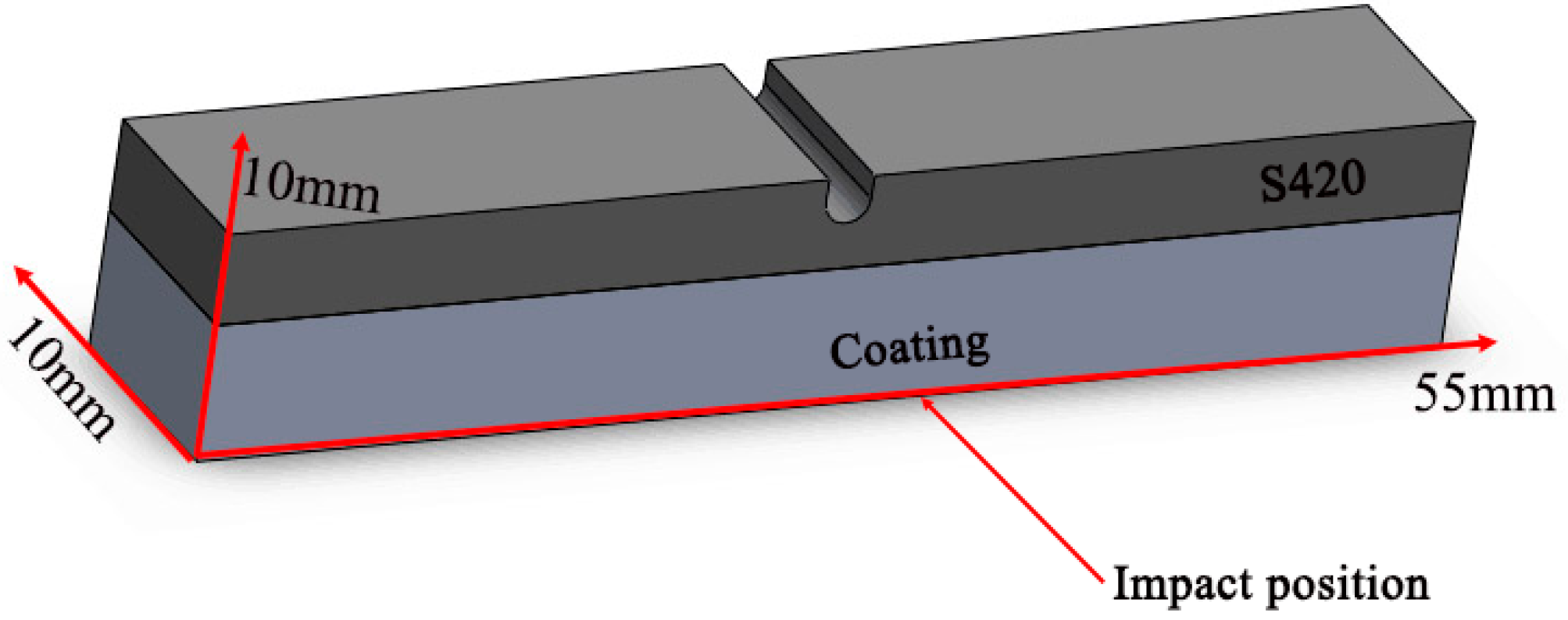
The microstructure and element composition of the coating were characterized by JSM-6510 scanning electron microscope (SEM, JEOL, Tokyo, Japan) and energy-dispersive spectroscopy (EDS, JEOL, Tokyo, Japan), and the phase composition of the coating was analyzed by X-ray diffractometer (XRD, Rigaku, Tokyo, Japan). The hardness of the sample was measured by 430SVD Vickers hardness tester (PROCEQ, Schwerzenbach, Switzerland). The test method was parallel to the horizontal section direction, the loading load was 200 g, the loading time was 15 s, a point was hit every 50 μm from the surface of the cladding layer to the substrate, and the average value was measured three times at the same depth level. The wear properties of the coating were tested by reciprocating sliding friction and wear tester (Chinese Academy of Sciences, China). The test conditions and technological parameters of wear are as follows, steel ball (grinding material), air (test medium), loading load of 250 g, wear scar radius of 4 mm, running time of 30 min. After the test was completed, the wear weight loss was measured by BT25S electronic analysis balance (Sartorius, Goettingen, Germany), and the wear scar morphology was observed by scanning electron microscope. The Charpy U-shaped notched impact specimen is cut parallel to the laser scanning direction along the cladding layer, and the sample size is 10 mm × 10 mm × 55 mm, which ensures that all the impact toughness specimens are in the cladding region, as shown in Figure 2. The impact test was carried out with JXB-300 pendulum impact tester. After the experiment was completed, the impact fracture was observed and analyzed by VHX-1000C optical profiler (KEYENCE, Osaka, Japan) and scanning electron microscope (SEM). The corrosion resistance of the coating was evaluated by CS350 electrochemical workstation (Corrtest, Wuhan, China). The test medium is a 3.5% NaCl solution, the electrochemical workstation uses a three-electrode system, the working electrode is sample, the reference electrode is saturated calomel electrode, and the auxiliary electrode is platinum electrode. The potentiodynamic scanning rate is 1 mV/s, the sampling frequency is 0.5 Hz, the measuring potential range is −1 to 1 V, and the test time is 1800 s. The frequency range measured by EIS (Electrochemical Impedance Spectroscopy) is 10−1 to 105 and the test time is 300 s. After the test is completed, the data will be fitted by ZSimDemo software.
3. Results and Discussion
3.1. Microstructures Analysis
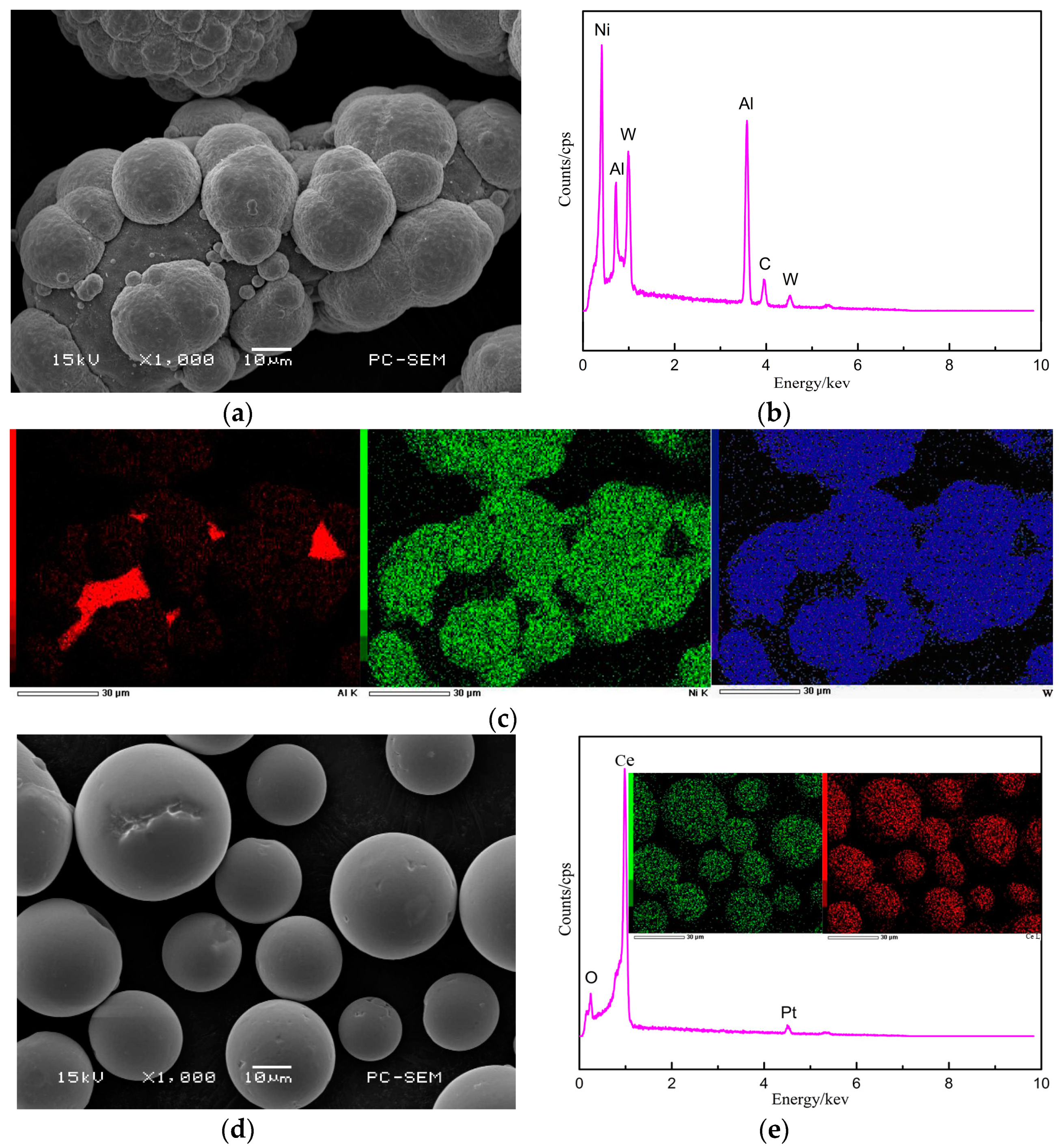
Figure 3 shows the morphology and energy spectrum analysis of the powder used in cladding. The particle size of Al powder is about 80 μm and the morphology is irregular. The morphology of WC powder is regular, WC powder distributed on the surface of Al powder, and the particle size is about 20 μm. After ball-milling, the mixed powder does not produce impurity elements. The morphology of CeO2 powder is regular spherical, the particle size is 15 to 30 μm, and the element distribution is uniform.
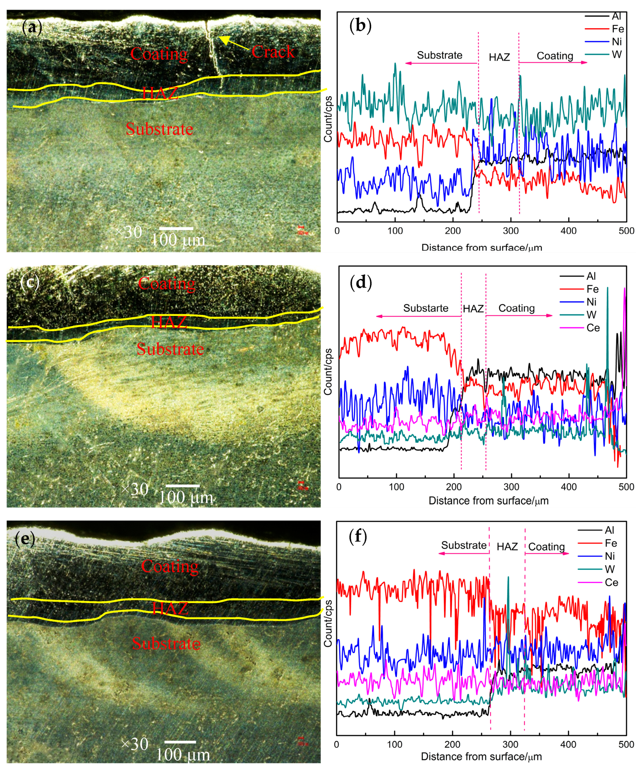
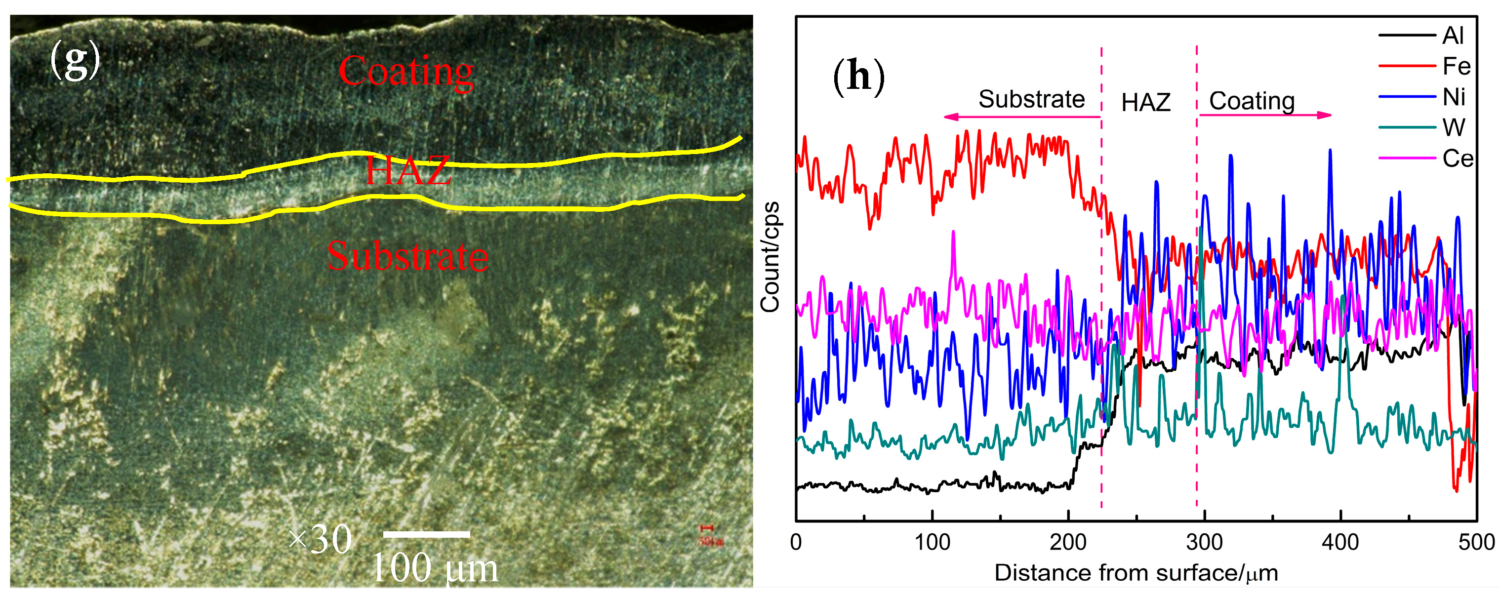
Figure 4 shows the cross section morphology of the cladding coating prepared with different CeO2 content. When the rare earth CeO2 is not added, an obvious crack appears in the cross section of the coating, and the crack gradually extends to the heat affected zone (HAZ). The elements in the coating region are mainly composed of Al, Fe, Ni, and W, and the distribution of Ni and W elements has great fluctuations. The appearance of Fe elements shows that the Fe in the substrate diffuses into the coating through the molten pool, as a result, the interface between the substrate and the coating is metallurgical bonded [21]. The depth of HAZ is 70 μm and the thickness of coating is 700 μm. According to the formula of dilution rate, it can be concluded that the dilution rate of coating is 9% without adding rare earth. When the rare earth content is 1%, the cross section of the coating is smooth and there are no macroscopic defects. The main elements in the coating are Al, Fe, Ni, W, and Ce. The depth of HAZ is 50 μm and the dilution rate is 6.6%, the bonding zone between the coating and the substrate forms a reasonable composition gradient, and the microstructure of the coating tends to be homogenized. When the content of CeO2 increased to 1.5%, pores began to appear in the coating, but the number of pores was less. The distribution of W element in the coating fluctuates obviously, the depth of HAZ is expanded to ~60 μm, and the dilution rate is gradually increased to 7.8%. When the rare earth content increases to 2%, the cross section of the coating is rough, the distribution of Ni and W elements is uneven, and the dilution rate increases to 8.4%.
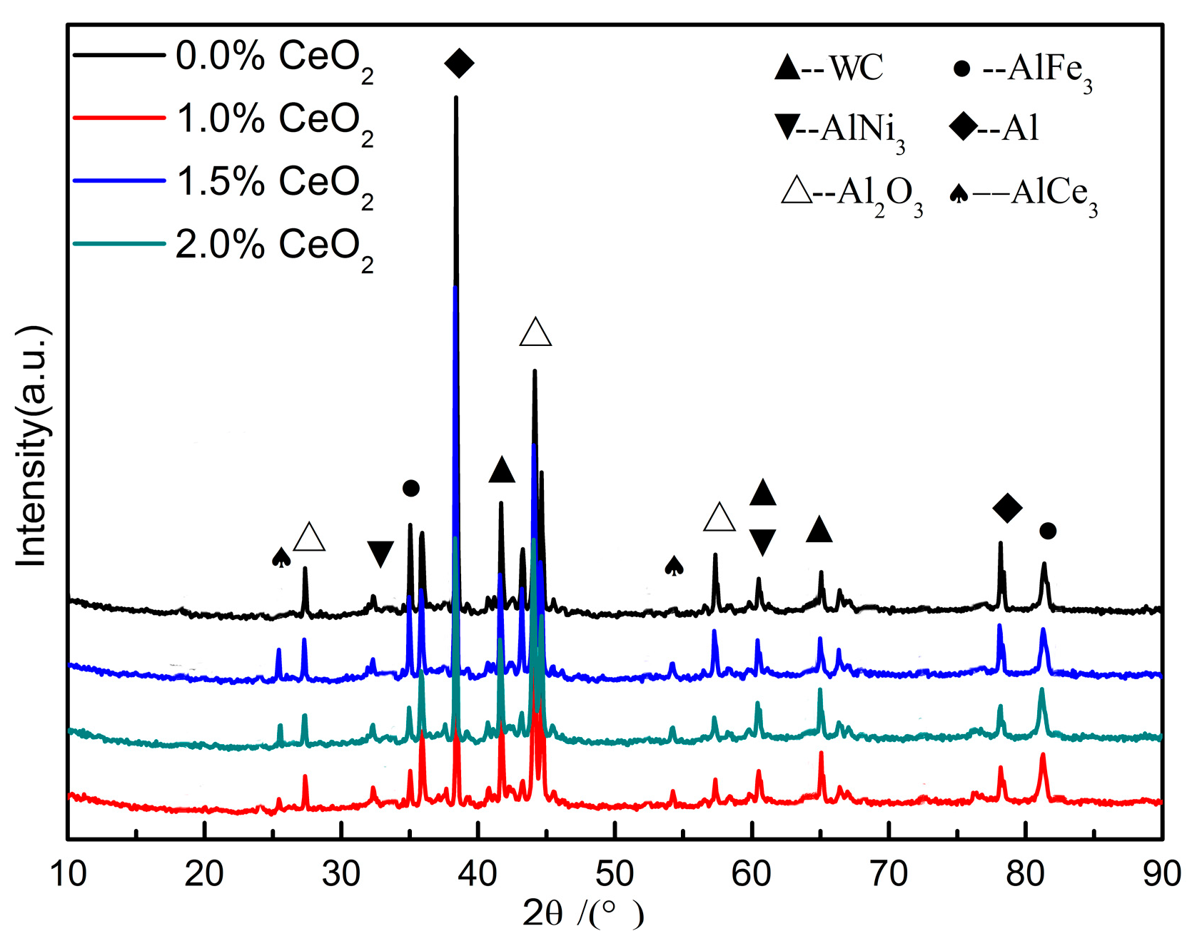
The prepared coating was characterized by XRD, and the XRD pattern is shown in Figure 5. It can be seen that the coating is mainly composed of matrix Al phase, continuous-phase, and hard reinforced-phase WC. The impurity phase of the coating with rare earth addition is obviously less than that of the coating without rare earth, and the crystal diffraction peaks of AlCe3 phase appear at approximately 25° and 55°, which indicates that rare earth CeO2 decomposes and reacts with Al at high temperature in order to purify the grain [22]. The appearance of AlFe3 phase shows that the Fe element in the substrate diffuses into the coating, resulting in the metallurgical bonding between the substrate and the coating [23]. In addition, the diffraction peak intensity of Al2O3 phase of the coating without rare earth addition is higher than that of other rare earth coatings, which indicates that rare earth has a certain oxidation resistance of the coating. The AlNi3 peak appears in all the four coatings. According to the calculated results of Gibbs free energy, the temperature of laser cladding is higher than 1000 K, and the AlNi3 phase is relatively stable.
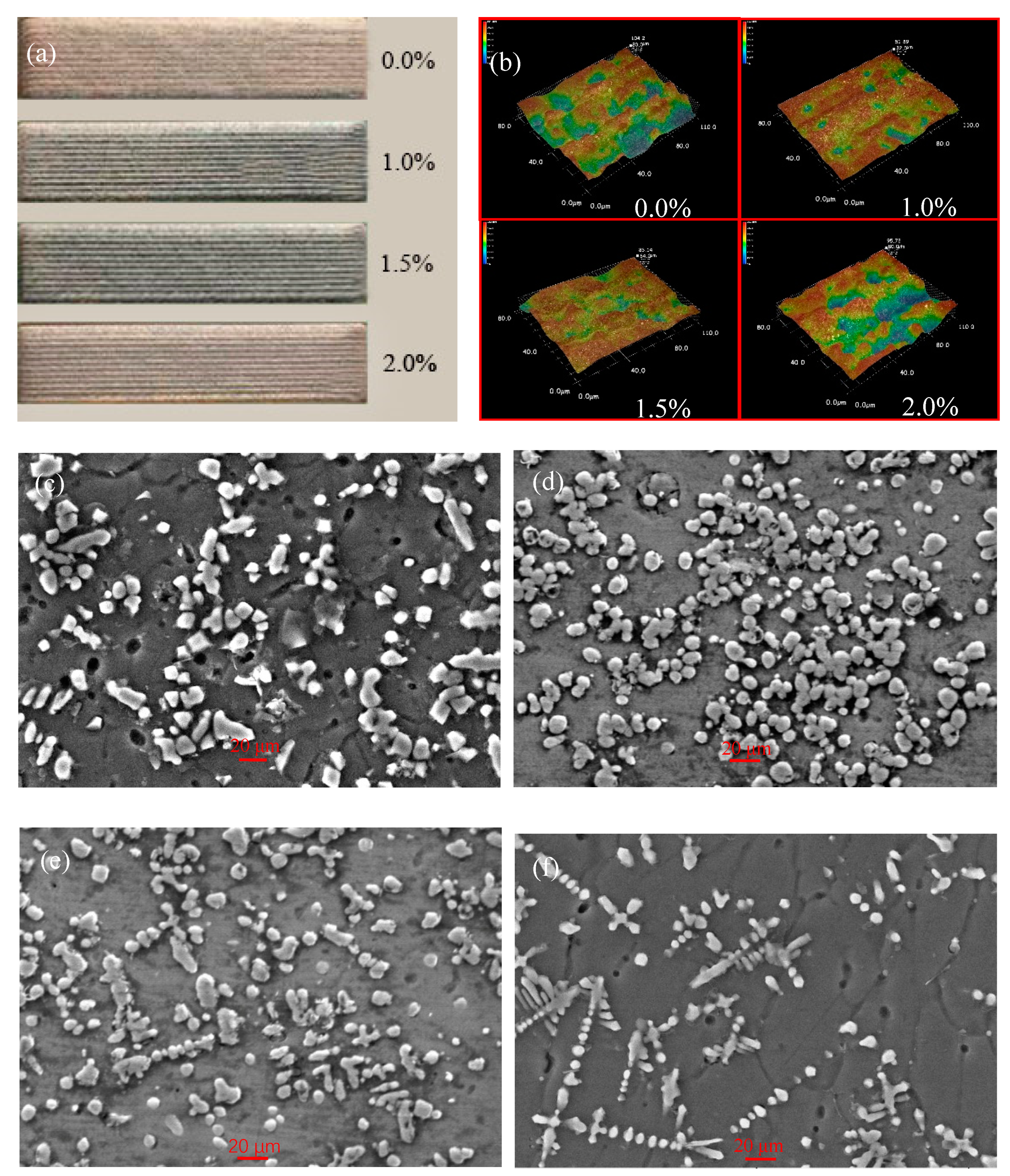
Figure 6 shows the macro-morphology, surface three-dimensional morphology and micromorphology of the coating. From Figure 6a, it can be seen that after the addition of rare earth CeO2, the surface of the coating is flat, the color is darker, the surface has metallic luster, and there are no macroscopic defects. From the perspective of three-dimensional morphology and microscopic morphology, when the rare earth CeO2 is not added, the surface of the coating is uneven, the roughness is large, and the surface shows undulating ripples. The grains are coarse and bonded to each other, showing rod shape and block shape [24]. When the content of CeO2 is 1%, the surface flatness of the coating is higher than that of the coating without rare earth addition, and the grains in the coating are obviously refined, showing granular shape and uniform distribution. This is mainly due to the fact that the addition of a small amount of rare earth can reduce the melting temperature, shorten the melting time, improve the flowability of the molten pool and facilitate the homogenization of the elements. When the content of CeO2 is 1.5%, it can be seen that the surface of the coating is relatively flat, but there are fewer pores and the microstructure of the coating is granular and flake. When the CeO2 content is further increased, the wavy pattern appears on the surface of the coating, the surface becomes uneven, the pores increase, and the tissue distribution is uneven. Therefore, the appropriate amount of rare earth can improve the quality of the cladding layer and refine the grain, but when the content of rare earth CeO2 is more than 1.5%, the quality of the coating begins to decline. Because of the strong electronegativity of rare earth, it shows strong chemical properties when the content is low, which can fill the defects of alloy phase in the molten pool, reduce the surface tension, promote the effective number of nuclei, and restrain the crystallization process, which leads to microstructure refinement. When the rare earth is excessive, the rare earth elements will dissolve in some metal compounds, resulting in less segregation at the grain boundary, reducing the undercooling at the grain boundary, promoting the activity of the grain boundary, and making the microstructure of the coating larger and the quality of cladding lower.
3.2. Properties Analysis
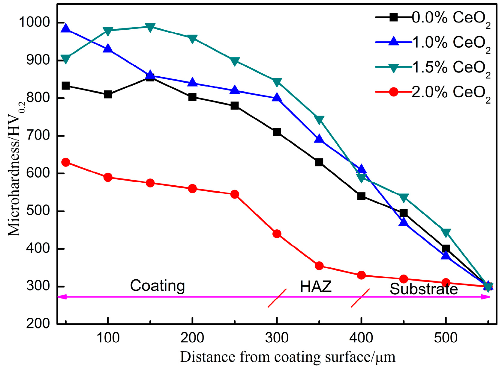
The microhardness distribution of the cladding coating is shown in Figure 7. According to the graph, the hardness of the four different coatings has the same trend, and the hardness decreases gradually from the coating surface to the substrate, especially in the heat-affected zone. In the bonding area between the substrate and the coating, the hardness of the coating gradually becomes stable. When the content of CeO2 is 1.0%, the maximum surface hardness of the coating is 983.3 HV0.2, which is nearly twice as much as that of the substrate. When the CeO2 content increases to 1.5%, the surface hardness of the coating decreases by 8%, and when the CeO2 content increases to 2.0%, the hardness of the coating decreases by 35%. It can be seen that the addition of appropriate amount of rare earth CeO2 can significantly improve the hardness of the cladding layer. When the content of CeO2 is more than 1%, the hardness increase trend is not obvious. On the one hand, because the strength of the metal is negatively related to the grain size, the smaller the grain size, the greater the strength of the metal and the higher the hardness of the material; on the other hand, in the nondynamic equilibrium process of laser cladding, the addition of rare earth elements can play the role of solid solution strengthening, which distorts the lattice size and promotes the improvement of hardness. Therefore, when the content of rare earth CeO2 is 1.0%, the hardness of the coating is the best.
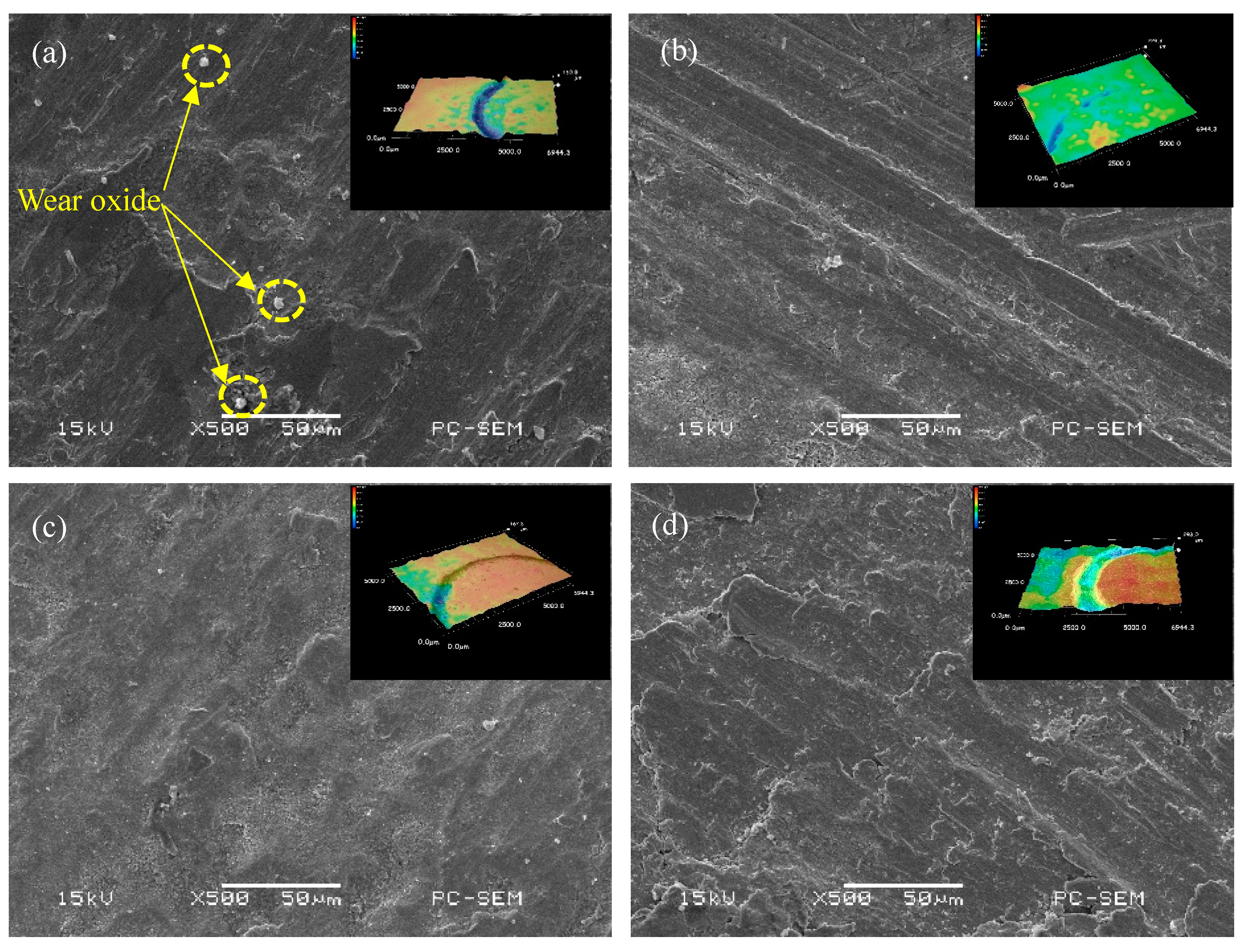
Table 2 shows the results of the wear parameters of the coating. When CeO2 is not added, the wear rate of the coating is 1.01 × 10⁻⁵ mm3·N−1·s−1. When CeO2 is added, the wear rate of the coating is obviously lower than that of the coating without CeO2, but it is not that the higher the CeO2 content is, the lower the wear rate of the coating is. When the CeO2 content is more than 1.5%, the wear rate of the coating decreases, and when it reaches 2.0%, the wear rate of the coating is close to that of the unadded rare earth coating. Figure 8 shows the worn morphology of the coating. When CeO2 is not added, white granular wear oxide appears on the worn surface, the worn surface is rough and the local damage is serious, and the wear mechanism is mainly micro-cutting and oxidation wear. When the content of CeO2 is 1.0%, the worn surface is flat and shallow ploughing appears, and the main wear mechanism is abrasive wear. When the content of CeO2 is 1.5%, there are pits and local damage on the worn surface and the wear mechanism is mainly micro-cutting. When the content of CeO2 is 2.0%, the worn surface is seriously damaged, and the main wear mechanism is micro-cutting and adhesive wear [25,26]. Based on the above results, it can be seen that rare earth elements have a certain effect on the wear resistance of the coating. The addition of appropriate amount of CeO2 can refine the microstructure, reduce the dendrite arm spacing and improve the toughness of the coating. When the content of CeO2 is more than 1%, the flowability of the molten pool decreases, which leads to the increase of the internal inclusions formed by cerium oxide and other components. In addition, in the process of solidification in the molten pool, deoxidation of CeO2 is reduced, so that the bubbles and inclusions are not easy to be discharged and inclusion in the coating increases, which leads to the decrease of plasticity and toughness and the wear resistance of the coating.
Table 3 shows the impact test results of the impact specimen. It can be seen from the table that the impact toughness of the coating is 32.25 J/cm2 without the addition of CeO2. When the content of CeO2 is 1%, the impact toughness of the coating is the highest, which reaches 42.27 J/cm2. When the CeO2 content is further increased, the impact toughness of the coating decreases. When the CeO2 content reaches 2%, the impact toughness of the coating is almost the same as that of the coating without CeO2, which is maintained at 32 J/cm2. After laser cladding, the impact toughness of the substrate (28.5 J/cm2) can be increased up to 48%, and the toughness is obviously improved. Due to the characteristics of rapid solidification of laser cladding, the boundary and phase interface between dendrite and eutectic per unit volume will increase, and the increase of interface will hinder the movement of dislocations. Moreover, due to the laser thermal radiation effect, the high density dislocation martensite is formed in the heat shadow region, which is beneficial to improve the impact properties. On the other hand, due to the fine grain strengthening effect of rare earth CeO2, it can effectively prevent the growth of grains, hinder the movement of dislocations, increase the difficulty of crack propagation, and effectively improve the comprehensive mechanical properties of materials.
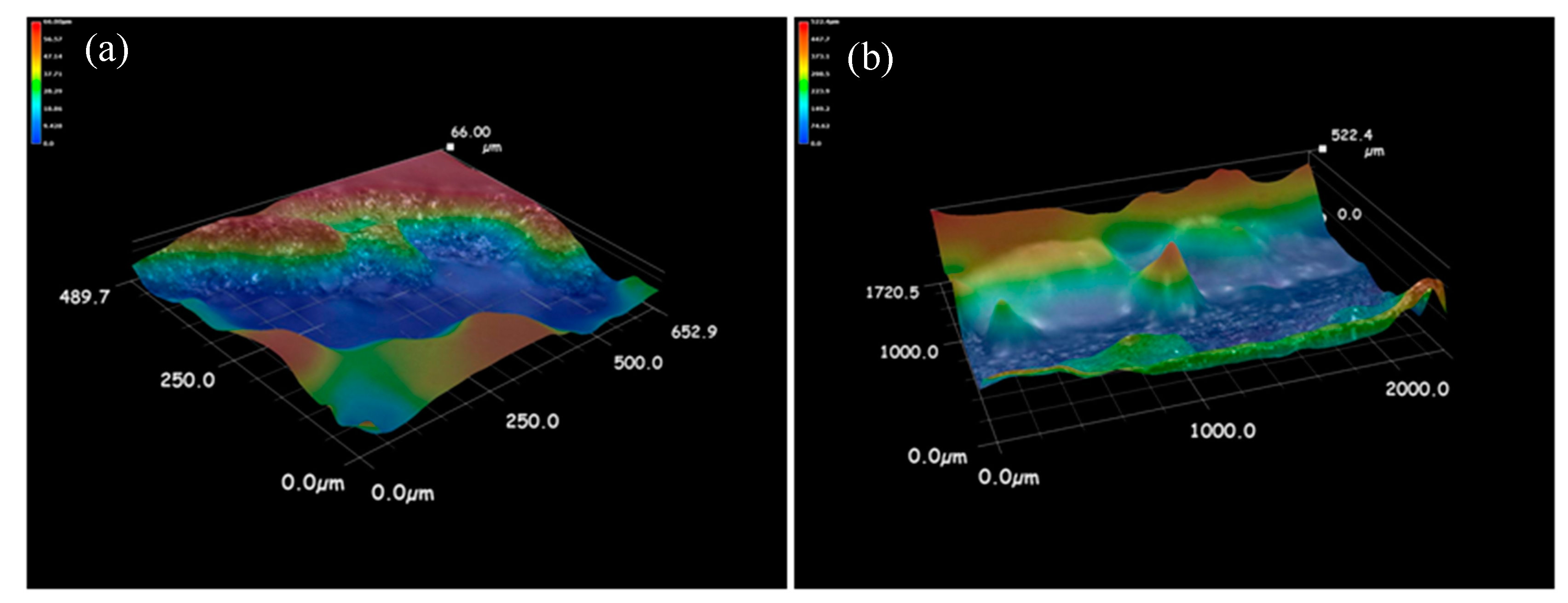
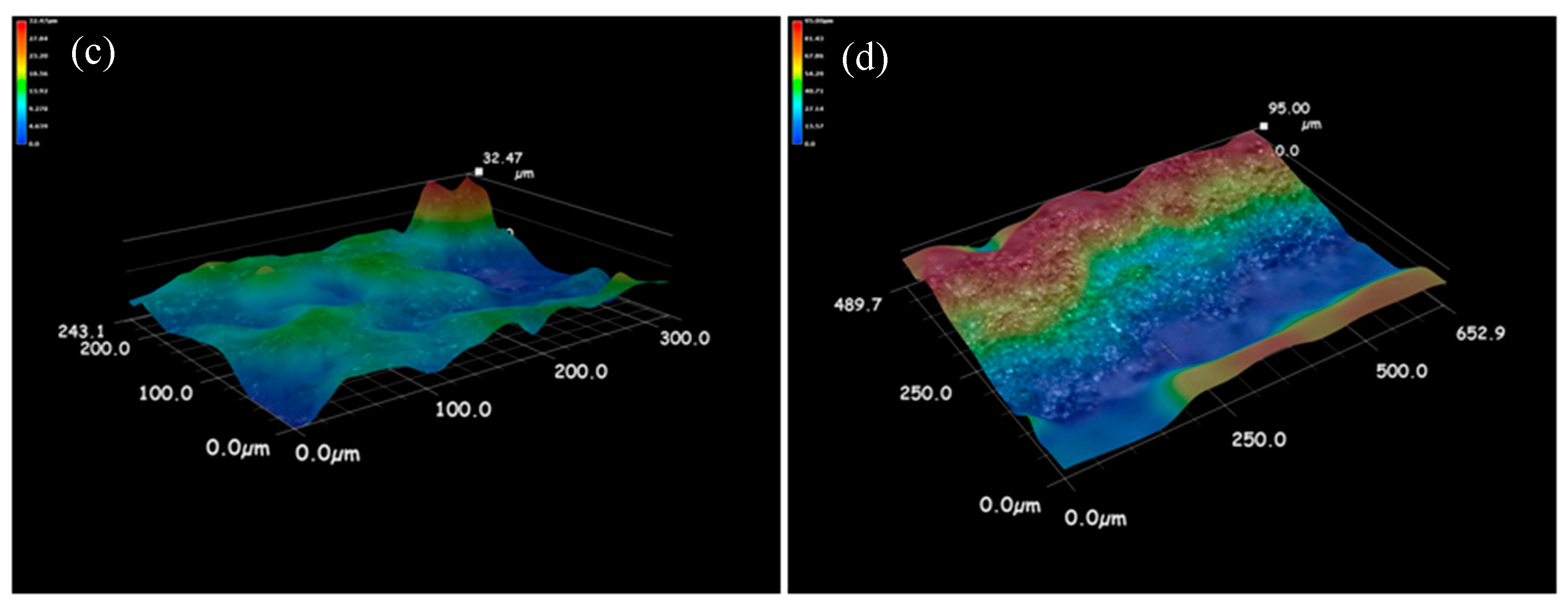
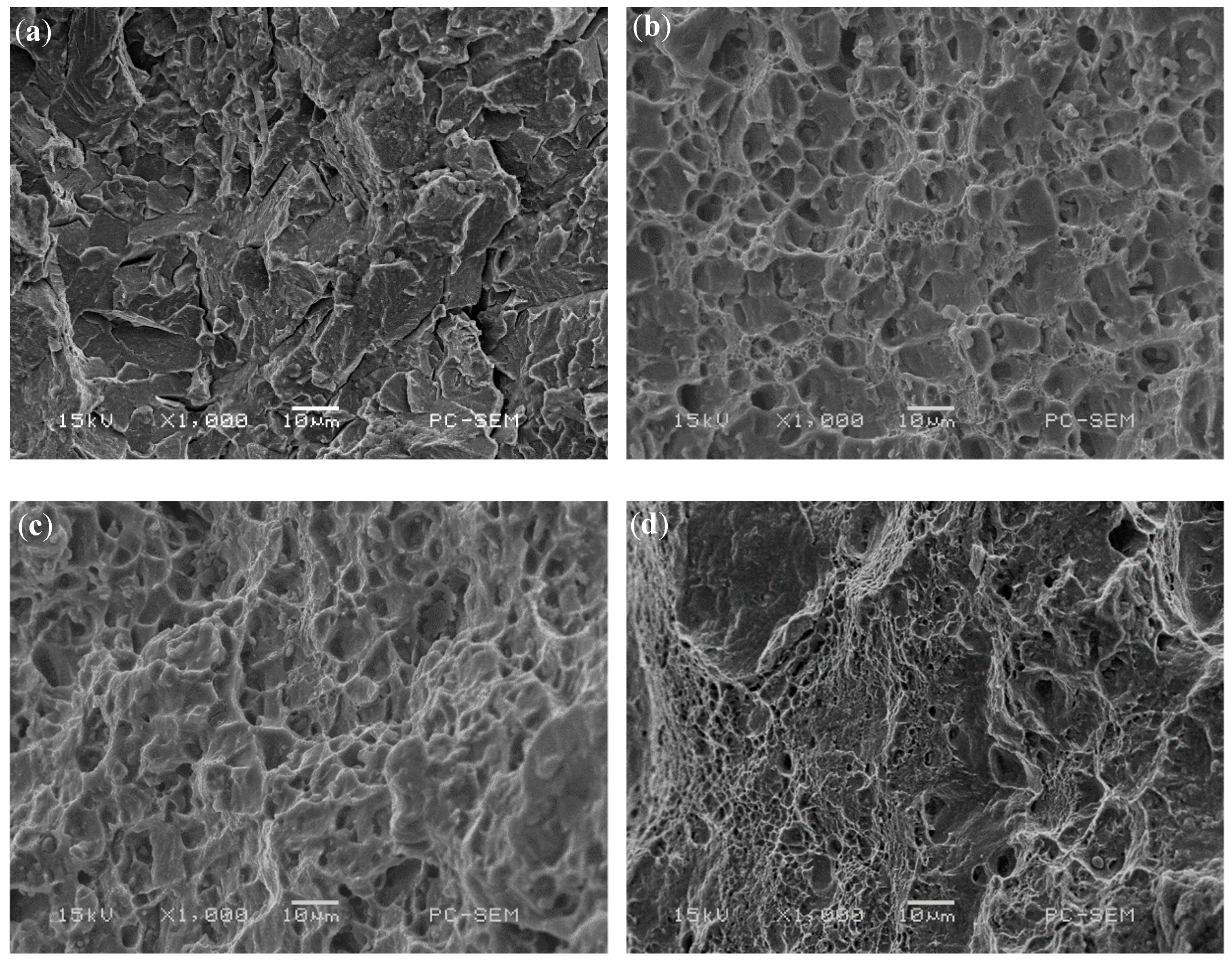
Figure 9 shows the 3D morphology of the fracture surface of the impact specimen. It can be seen that the fracture surface of the coating with rare earth is obviously uneven, and the specific surface area of the fracture is larger than that of the coating without rare earth. Because the impact fracture direction is perpendicular to the interface between the enhanced zone and the heat affected zone, when the crack propagation front enters the heat affected zone from the enhanced zone, the changes of hardness and toughness will make the crack propagation direction deflected or forked. This deflection and bifurcation increases the total area of the crack and increases the total energy absorbed by the crack propagation, which leads to the increase of the impact energy. Figure 10 shows the microscopic morphology of impact fracture. When CeO2 is not added, the fracture surface of the specimen is mainly composed of a small cleavage plane, which is connected by small and curved tear edges, and no dimples are found. At the same time, there are obvious river patterns and cleavage steps on the large cleavage plane, the fracture characteristics are quasi-cleavage fracture, and the surface has radial steps, which is the characteristic of brittle fracture [27]. When the CeO2 content is 1% and 1.5%, the fracture surface of the specimen is composed of dimples, and the plastic deformation mainly occurs in the process of crack propagation. In the same direction, the dimple of 1% CeO2 content sample is deeper and larger than that of 1.5% CeO2 content sample. This shows that the plastic deformation of 1% CeO2 content coating is larger than that of 1.5% CeO2 content coating under impact load, and the plastic deformation work consumed during crack propagation is larger than that of 1.5% CeO2 content coating. When the content of CeO2 is 2%, the fracture morphology of the sample is composed of a large number of dimples and cleavage planes, and the dimple band is surrounded by cleavage planes and tear edges, and the secondary crack is not obvious, which is a typical quasi-cleavage fracture morphology [28]. It can be seen that the fracture mechanism of impact specimen is the mixed fracture of dimple fracture and dissociative fracture. To sum up, the impact toughness of the coating with rare earth is better than that of the sample without rare earth.
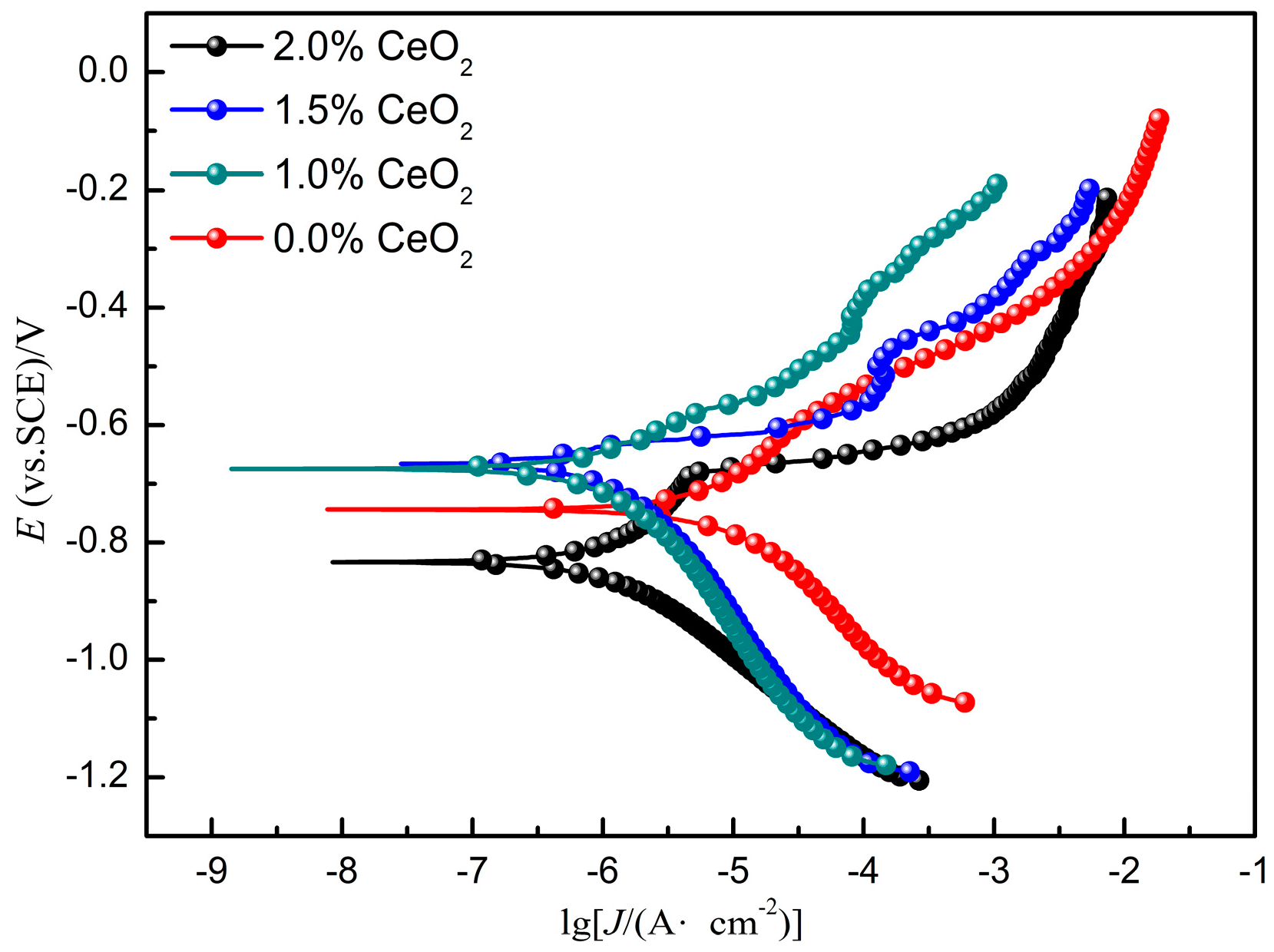
Figure 11 shows the potentiodynamic polarization curves of cladding coatings with different CeO2 content combined with the polarization curve fitting parameters shown in Table 4. Passivation occurred in all the four coatings. Without rare earth addition, the corrosion potential of the coating is −0.7348 V, the pitting potential is approximately −0.7 V, and the width of the passivation range is 0.3 V. When the rare earth content is 1%, the self-corrosion potential increases rapidly to −0.6 V, and the pitting potential also increases to −0.5 V. With the further increase of CeO2 content, the self-corrosion potential and pitting potential of the coating decreased. When the content of CeO2 reaches 2%, the self-corrosion potential and current density of the coating are lower than those of the coating without rare earth. There are two main reasons for this phenomenon. First, CeO2 can refine the crystal structure and improve the crystal composition segregation, so that the structure can be purified and the grain boundary corrosion rate can be delayed. Second, CeO2 can improve the content and distribution of corrosion resistance elements such as Ni and Ti, promote the corrosion resistance of the coating.
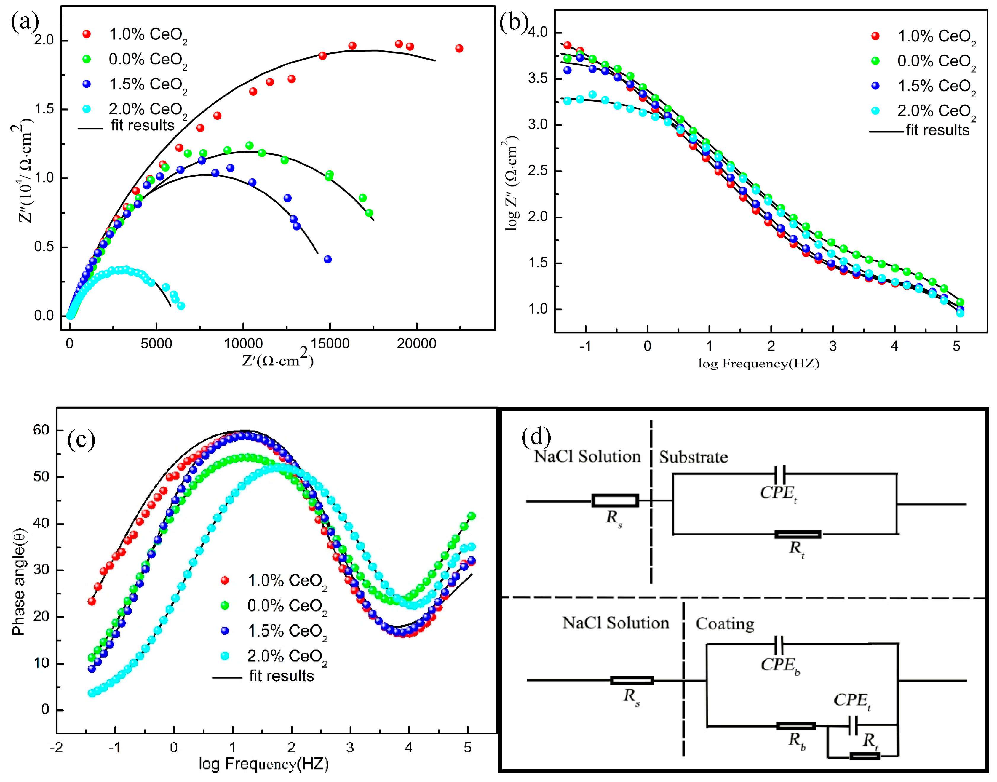
In order to further study the electrochemical behavior of CeO2 on coatings, the impedance spectra of different coatings were measured, as shown in Figure 12. It can be seen that on the Nyquist diagram, the four kinds of coatings show capacitive arc at high frequency. The relationship between the radius of capacitance arc and the content of CeO2 is 2% < 1.5% < 0.0% < 1%. The larger the radius of arc resistance is, the better the corrosion resistance is. From the Bode diagram, we can see that all coatings correspond to two time constants at frequencies of 10 and 10,000. At low frequency, the impedance is higher when the content of CeO2 is 1.5%, 0.0%, and 1%. The interface reacted by capacitance arc resistance in low frequency region is corrosion product layer, and the interface reacted by capacitance arc resistance at high frequency is passivation film, because of the large phase angle, the passivation film is more compact [29]. When the content of CeO2 is 2.0%, the impedance in the low frequency region is low, and the interface reacted by the capacitance arc is caused by activation, indicating that the charge has been transferred, indicating the formation of pitting corrosion. Figure 12d shows the EIS equivalent circuit diagram. Rs represents the resistance of the corrosion medium, CPE represents the original of constant phase angle, Rb represents the resistance between the medium and the sample interface, and Rt represents the resistance on the coating surface dissolved by the corrosion medium. The corresponding equivalent circuit parameters are listed in Table 5, when the CeO2 content is 1.0%, the passivation film Rt of the coating is the largest, indicating that the corrosion resistance of the coating is the best.
4. Conclusions
- (1)
- WC-reinforced Al-based composite coating with added CeO2 was prepared by laser cladding. The addition of CeO2 did not change the phase composition of the coating. Appropriate amount of CeO2 can enhance the flowability of the molten pool, refine the microstructure of the coating, and make the distribution of elements in the coating uniform. However, excessive CeO2 makes the diffusion of the molten pool difficult, and CeO2 will dissolve into the metal compounds, which makes the microstructure of the coating become thick again.
- (2)
- Appropriate amount of rare earth CeO2 can significantly improve the hardness of the cladding coating. When the content of CeO2 is more than 1%, the fine grain strengthening effect decreases gradually, the dislocation movement increases, and the inclusions in the coating increase, resulting in the decrease of plasticity and impact toughness of the coating. Wear resistance is also reduced.
- (3)
- The coating prepared with different CeO2 content has higher impedance and higher corrosion resistance than that of the substrate. When the content of CeO2 is 1%, the coating shows its best corrosion resistance.
Author Contributions
For this paper, Z.C. conceived and designed the experiments; W.W. performed experiments, analyzed the data, and finished writing the paper; S.F. analyzed the data and contributed materials.
Funding
The financial support for this research by the National Natural Science Foundation of China under grant No. 11702256 is gratefully acknowledged.
Conflicts of Interest
The authors declare no conflicts of interest.
References
- López-Ortega, A.; Bayón, R.; Arana, J.L. Evaluation of protective coatings for offshore applications. Corrosion and tribocorrosion behavior in synthetic seawater. Surf. Coat. Tech. 2018, 349, 1083–1097. [Google Scholar] [CrossRef]
- Sun, X.; Huang, D.; Wu, G. The current state of offshore wind energy technology development. Energy 2012, 41, 298–312. [Google Scholar] [CrossRef]
- Alam, M.A.; Sherif, E.S.M.; Al-Zahrani, S.M. Fabrication of various epoxy coatings for offshore applications and evaluating their mechanical properties and corrosion behavior. Int. J. Electrochem. Sci. 2013, 8, 3121–3131. [Google Scholar]
- Zhou, Y.L.; Zhang, X.J.; Liu, Z.Y.; Misra, R.D.K. Investigation on tempering of granular bainite in an offshore platform steel. Mater. Sci. Eng. A 2015, 626, 352–361. [Google Scholar] [CrossRef]
- Zhou, Y.L.; Jia, T.; Zhang, X.J.; Liu, Z.Y.; Misra, R.D.K. Microstructure and toughness of the CGHAZ of an offshore platform steel. J. Mater. Process. Technol. 2015, 219, 314–320. [Google Scholar] [CrossRef]
- Travanca, J.; Hao, H. Dynamics of steel offshore platforms under ship impact. Appl. Ocean. Res. 2014, 47, 352–372. [Google Scholar] [CrossRef]
- Zhou, Y.L.; Chen, J.; Liu, Z.Y. Corrosion Behavior of Rusted 550 MPa Grade Offshore Platform Steel. J. Iron. Steel. Res. Int. 2013, 20, 66–73. [Google Scholar] [CrossRef]
- Yang, Y.; W, Q.J.; He, Z.; Jia, Z.Y.; Zhang, X.W. Seismic Collapse Performance of Jacket Offshore Platforms with Time-Variant Zonal Corrosion Model. Appl. Ocean. Res. 2019, 84, 268–278. [Google Scholar] [CrossRef]
- Ma, H.B.; Yang, Y.; He, Z.; Zhang, Y.H.; Ji, F. Experimental study on mechanical properties of steel under extreme cyclic loading considering pitting damage. Ocean. Eng. 2019, 186, 106091. [Google Scholar] [CrossRef]
- Zhou, S.F.; Xu, Y.B.; Liao, B.Q.; Sun, Y.J.; Dai, X.Q.; Yang, J.X.; Li, Z.Y. Effect of laser remelting on microstructure and properties of WC reinforced Fe-based amorphous composite coatings by laser cladding. Opt. Laser. Technol. 2018, 103, 8–16. [Google Scholar] [CrossRef] [Green Version]
- Li, W.; Xu, P.Q.; Wang, Y.Y.; Zou, Y.; Gong, H.Y.; Lu, F.G. Laser synthesis and microstructure of micro- and nano-structured WC reinforced Co-based cladding layers on titanium alloy. J. Alloys Compd. 2018, 749, 10–22. [Google Scholar] [CrossRef]
- Leunda, J.; Sanz, C.; Soriano, C. Laser cladding strategies for producing WC reinforced NiCr coatings inside twin barrels. Surf. Coat. Tech. 2016, 307, 720–727. [Google Scholar] [CrossRef]
- Ye, F.X.; Hojamberdiev, M.; Xu, Y.H.; Zhong, L.S.; Yan, H.H.; Chen, Z. Volume Fraction Effect of V8C7 Particulates on Impact Toughness and Wear Performance of V8C7/Fe Monolithic Composites. J. Mater. Eng. Perform. 2014, 23, 1402–1407. [Google Scholar] [CrossRef]
- He, X.; Song, R.G.; Kong, D.J. Microstructures and properties of Ni/TiC/La2O3 reinforced Al based composite coatings by laser cladding. Opt. Laser. Technol. 2019, 117, 18–27. [Google Scholar] [CrossRef]
- Chen, W.J.; Chen, H.; Li, C.C.; Wang, X.L.; Cai, Q. Microstructure and fatigue crack growth of EA4T steel in laser cladding remanufacturing. Eng. Fail. Anal. 2017, 79, 120–129. [Google Scholar] [CrossRef]
- Fan, Y.; Jin, G.; Cui, X.F.; Li, Y.; Gao, Z.H. Effect of Nb and CeO2 on the mechanical and tribology properties of Co-based cladding coatings. Surf. Coat. Tech. 2016, 288, 25–29. [Google Scholar] [CrossRef]
- Zhang, H.; Zou, Y.; Zou, Z.D.; Shi, C.W. Effects of CeO2 on microstructure and corrosion resistance of TiC-VC reinforced Fe-based laser cladding layers. J. Rare. Earth. 2014, 32, 1095–1100. [Google Scholar] [CrossRef]
- Sun, S.T.; Fu, H.H.; Ping, X.L.; Guo, X.Y.; Lin, J.; Lei, Y.P.; Wu, W.B.; Zhou, J.X. Effect of CeO2 addition on microstructure and mechanical properties of in-situ (Ti, Nb)C/Ni coating. Surf. Coat. Tech. 2019, 359, 300–313. [Google Scholar] [CrossRef]
- Yang, C.Y.; Luan, Y.K.; Li, D.Z.; Li, Y.Y. Effects of rare earth elements on inclusions and impact toughness of high-carbon chromium bearing steel. J. Mater. Sci. Technol. 2019, 35, 1298–1308. [Google Scholar] [CrossRef]
- Zhang, X.; Wei, W.Z.; Cheng, L.; Liu, J.; Wu, K.M.; Liu, M. Effects of niobium and rare earth elements on microstructure and initial marine corrosion behavior of low-alloy steels. Appl. Surf. Sci. 2019, 475, 83–93. [Google Scholar] [CrossRef]
- He, X.; Kong, D.J.; Song, R.G. Microstructures and Properties of Laser Cladding Al-TiC-CeO2 Composite Coatings. Materials 2018, 11, 198. [Google Scholar] [CrossRef] [PubMed]
- Li, J.N.; Chen, C.Z.; Wang, D.G.; Li, W. Microstructures and wear properties of YPSZ/CeO2 reinforced composites deposited by laser cladding. Compos Part B-Eng. 2012, 43, 896–901. [Google Scholar] [CrossRef]
- Luo, X.X.; Yao, Z.J.; Zhang, P.Z.; Gu, D.D. Al2O3 nanoparticles reinforced Fe-Al laser cladding coatings with enhanced mechanical properties. J. Alloy. Compd. 2018, 755, 41–54. [Google Scholar] [CrossRef]
- Farahmand, P.; Liu, S.; Zhang, Z.; Kovacevic, R. Laser cladding assisted by induction heating of Ni–WC composite enhanced by nano-WC and La2O3. Ceram Int. 2014, 40, 15421–15438. [Google Scholar] [CrossRef]
- Zhao, N.; Tao, L.; Guo, H.; Zhang, M.Q. Effect of Ultra-fine WC Particles on Microstructural Evolution and Wear Behavior of Ni-Based Nano-CeO2 Coatings Produced by Laser. Rare. Metal. Mat. Eng. 2018, 47, 20–25. [Google Scholar]
- Chen, T.; Fun, D.F.; Wu, F.; Wang, H.J. Effect of CeO2 on Microstructure and Wear Resistance of TiC Bioinert Coatings on Ti6Al4V Alloy by Laser Cladding. Materials 2018, 11, 58. [Google Scholar] [CrossRef] [PubMed]
- Li, H.F.; Duan, Q.Q.; Zhang, P.; Zhou, X.H.; Wang, B.; Zhang, Z.F. The quantitative relationship between fracture toughness and impact toughness in high-strength steels. Eng. Fract. Mech. 2019, 211, 362–370. [Google Scholar] [CrossRef]
- Haghdadi, N.; Cizek, P.; Hodgson, P.D.; Beladi, H. Microstructure dependence of impact toughness in duplex stainless steels. Mater. Sci. Eng. A 2019, 745, 369–378. [Google Scholar] [CrossRef]
- Dai, N.W.; Zhang, L.C.; Zhang, J.X.; Chen, Q.M.; Wu, M.L. Corrosion behavior of selective laser melted Ti-6Al-4V alloy in NaCl solution. Corros. Sci. 2016, 102, 484–489. [Google Scholar] [CrossRef]
Figure 1.
Schematic of laser cladding process.

Figure 2.
Schematic diagram of impact specimens.

Figure 3.
Morphologies (a,d) and energy-dispersive spectroscopy (EDS) analysis (b,c,e) of powders: (a) Ni/Al/WC mixed powder and (d) CeO2 powder.
Figure 3.
Morphologies (a,d) and energy-dispersive spectroscopy (EDS) analysis (b,c,e) of powders: (a) Ni/Al/WC mixed powder and (d) CeO2 powder.

Figure 4.
Cross section morphology (a,c,e,g) and linear scanning diagram (b,d,f,h) of coatings with different CeO2 content: (a,b) 0.0% CeO2, (c,d) 1.0% CeO2, (e,f) 1.5% CeO2, and (g,h) 2.0% CeO2.
Figure 4.
Cross section morphology (a,c,e,g) and linear scanning diagram (b,d,f,h) of coatings with different CeO2 content: (a,b) 0.0% CeO2, (c,d) 1.0% CeO2, (e,f) 1.5% CeO2, and (g,h) 2.0% CeO2.


Figure 5.
XRD patterns of coatings with different CeO2 content.

Figure 6.
Macro-morphology (a), three-dimensional morphology (b), and micromorphology (c,d,e,f) of coatings with different CeO2 content: (c) 0.0% CeO2, (d) 1.0% CeO2, (e) 1.5% CeO2, and (f) 2.0% CeO2.
Figure 6.
Macro-morphology (a), three-dimensional morphology (b), and micromorphology (c,d,e,f) of coatings with different CeO2 content: (c) 0.0% CeO2, (d) 1.0% CeO2, (e) 1.5% CeO2, and (f) 2.0% CeO2.

Figure 7.
Microhardness distribution of coatings with different CeO2 content.

Figure 8.
Wear micro-morphology and three-dimensional morphology of coatings with different CeO2 content: (a) 0.0% CeO2, (b) 1.0% CeO2, (c) 1.5% CeO2, and (d) 2.0% CeO2.
Figure 8.
Wear micro-morphology and three-dimensional morphology of coatings with different CeO2 content: (a) 0.0% CeO2, (b) 1.0% CeO2, (c) 1.5% CeO2, and (d) 2.0% CeO2.

Figure 9.
3D morphology of impact fracture surface with different CeO2 content: (a) 0.0% CeO2, (b) 1.0% CeO2, (c) 1.5% CeO2, and (d) 2.0% CeO2.
Figure 9.
3D morphology of impact fracture surface with different CeO2 content: (a) 0.0% CeO2, (b) 1.0% CeO2, (c) 1.5% CeO2, and (d) 2.0% CeO2.


Figure 10.
Impact fracture morphologies of Coatings with different CeO2 content: (a) 0.0% CeO2, (b) 1.0% CeO2, (c) 1.5% CeO2, and (d) 2.0% CeO2.
Figure 10.
Impact fracture morphologies of Coatings with different CeO2 content: (a) 0.0% CeO2, (b) 1.0% CeO2, (c) 1.5% CeO2, and (d) 2.0% CeO2.

Figure 11.
Polarization curves of coatings with different CeO2 content.

Figure 12.
Impedance spectrum of coating in 3.5% NaCl solution: (a) Nyquist plot, (b,c) Bode plot, and (d) equivalent circuit.
Figure 12.
Impedance spectrum of coating in 3.5% NaCl solution: (a) Nyquist plot, (b,c) Bode plot, and (d) equivalent circuit.


Table 1.
Chemical composition of S420 steel (wt.%).
| C | Si | Mn | P | Cr | S | Ni | Mo | Al | Ti | Nb | Cu | Fe |
|---|---|---|---|---|---|---|---|---|---|---|---|---|
| 0.07 | 0.20 | 1.52 | 0.004 | 0.02 | 0.035 | 0.44 | 0.01 | 0.052 | 0.013 | 0.018 | 0.23 | 97.38 |
Table 2.
Wear test results of coatings.
| CeO2 Content (wt.%) | Wear Width (μm) | Wear Depth (μm) | Wear Area (mm2) | Wear Volume (mm3) | Wear Rate (mm3·N−1·s−1) |
|---|---|---|---|---|---|
| 0.0 | 500.12 | 34.91 | 9.42 | 0.32 | 1.01 × 10⁻⁵ |
| 1.0 | 342.91 | 9.86 | 6.46 | 0.06 | 1.87 × 10⁻⁶ |
| 1.5 | 408.42 | 15.49 | 7.69 | 0.12 | 3.75 × 10⁻⁶ |
| 2.0 | 512.82 | 31.82 | 9.66 | 0.31 | 9.68 × 10⁻⁶ |
Table 3.
Impact test data of different coatings.
| CeO2 Contents (wt.%) | Impact Absorbing Energy Ak (J) | Fracture Surface Area S (cm2) | Impact Toughness αk (J/cm2) |
|---|---|---|---|
| 0.0 | 25.8 | 0.8 | 32.25 |
| 1.0 | 33.82 | 0.8 | 42.27 |
| 1.5 | 31.25 | 0.8 | 39.07 |
| 2.0 | 26.12 | 0.8 | 32.65 |
Table 4.
Electrochemical data of coatings with different contents of CeO2.
| CeO2 (wt.%) | Ecorr (V) | icorr (A/cm2) | βa/(mV) | βb/(mV) | Rp/(Ω·cm2) |
|---|---|---|---|---|---|
| 0.0 | −0.7348 | 3.7721 × 10⁻⁶ | 302.23 | 201.76 | 2.9228 × 10⁻⁵ |
| 1.0 | −0.6661 | 8.3794 × 10⁻⁷ | 150.73 | 122.74 | 3.9934 × 10⁻⁶ |
| 1.5 | −0.6745 | 7.7306 × 10⁻⁷ | 102.82 | 189.78 | 3.3773 × 10⁻⁶ |
| 2.0 | −0.8335 | 1.7053 × 10⁻⁶ | 208.49 | 227.39 | 2.2758 × 10⁻⁵ |
Table 5.
EIS data of substrate and coatings with different contents of CeO2.
| CeO2 (wt.%) | Rs (Ω·cm2) | Qb (Ω−1·s−n·cm−2) | Nb | Rb (Ω·cm2) | Qt (Ω−1·s−n·cm−2) | Nt | Rt (Ω·cm2) |
|---|---|---|---|---|---|---|---|
| 0.0 | 0.33 | 7.713 × 10⁻⁵ | 0.7024 | 26.55 | 8.277 × 10⁻⁵ | 0.7673 | 11,970 |
| 1.0 | 3.377 | 3.229 × 10⁻⁶ | 0.7649 | 18.66 | 9.661 × 10⁻⁵ | 0.7374 | 36,796 |
| 1.5 | 4.62 | 3.515 × 10⁻⁶ | 0.9551 | 13.66 | 9.670 × 10⁻⁵ | 0.673 | 35,230 |
| 2.0 | 0.3571 | 8.11 × 10⁻⁶ | 0.6638 | 36.25 | 8.824 × 10⁻⁵ | 0.675 | 20,000 |
© 2019 by the authors. Licensee MDPI, Basel, Switzerland. This article is an open access article distributed under the terms and conditions of the Creative Commons Attribution (CC BY) license (http://creativecommons.org/licenses/by/4.0/).
Share and Cite
MDPI and ACS Style
Wang, W.; Chen, Z.; Feng, S. Effect of CeO2 on Impact Toughness and Corrosion Resistance of WC Reinforced Al-Based Coating by Laser Cladding. Materials 2019, 12, 2901. https://0-doi-org.brum.beds.ac.uk/10.3390/ma12182901
AMA Style
Wang W, Chen Z, Feng S. Effect of CeO2 on Impact Toughness and Corrosion Resistance of WC Reinforced Al-Based Coating by Laser Cladding. Materials. 2019; 12(18):2901. https://0-doi-org.brum.beds.ac.uk/10.3390/ma12182901
Chicago/Turabian StyleWang, Weizhan, Zhigang Chen, and Shunshan Feng. 2019. "Effect of CeO2 on Impact Toughness and Corrosion Resistance of WC Reinforced Al-Based Coating by Laser Cladding" Materials 12, no. 18: 2901. https://0-doi-org.brum.beds.ac.uk/10.3390/ma12182901
Note that from the first issue of 2016, this journal uses article numbers instead of page numbers. See further details here.