The Development of Nanoalumina-Based Cement Mortars for Overlay Applications in Concrete Floors


Faculty of Civil Engineering, Wroclaw University of Science and Technology, Wybrzeże Wyspiańskiego 27, 50-370 Wrocław, Poland
*
Author to whom correspondence should be addressed.
Materials 2019, 12(21), 3465; https://0-doi-org.brum.beds.ac.uk/10.3390/ma12213465
Submission received: 14 September 2019
/
Revised: 16 October 2019
/
Accepted: 18 October 2019
/
Published: 23 October 2019
(This article belongs to the Special Issue Long-Term Behavior of Cementitious Materials and Reinforced Concrete Structures)
Abstract
:This article focuses on the development of nanoalumina-based cement mortars for overlay applications in concrete floors. It focuses on the effect of applying aluminum oxide (Al2O3) nanopowder to the cement mortar used to make the overlay, on the adhesion of this overlay to concrete substrate and on its functional properties. It was claimed that the addition of 0.5% of Al2O3 nanopowder has a positive effect on the adhesion of the cement mortar used to make the overlay to the substrate made of concrete. The prior studies performed using scanning electron microscopy (SEM) confirmed that the reason for the improvement in adhesion is the fact that cement mortar used to make the overlay with the addition of 0.5% of Al2O3 nanopowder is less porous than the reference mortar within the interphase. The article concurs that the most favorable results, in terms of lower abrasion resistance and higher subsurface tensile strength of the cement mortar used to make the overlay, are mainly brought about by adding 0.5% of Al2O3 nanopowder.
1. Introduction
In construction, in terms of durability, cement mortar used to make the overlay should primarily have an adequate adhesion to the concrete substrate [1,2,3]. According to [4,5,6,7], the pull-off adhesion of cement mortar used to make the overlay to the concrete substrate should be at least 0.5 MPa for newly made overlays. As highlighted in [8], in the case of repaired concrete elements, the value of pull-off adhesions should be at least 2 MPa and 1 MPa for structural and nonstructural repairs, respectively. As stated in [9,10,11,12], the properties of the cement mortar used to make the overlay are strongly influenced by the porosity, microcracks, moisture content, absorption rate and morphology of the substrate. Thus, according to recent literature, in order to obtain this adhesion at an appropriate level, mechanical treatment of the concrete substrate surface is applied [13,14,15]. Although sandblasting seems to be the most advantageous for many surfaces [16], as demonstrated in [17] for layered cement composites, it is beneficial to use shot-blasting in order to most efficiently treat the concrete substrate. Furthermore, texturing the surface of a concrete substrate has recently gained more attention [18,19]. What is more, surface exposure of the coarse aggregate of the substrate, and strengthening of the surface of the concrete substrate, are frequently done [20,21,22]. Increasingly, various additives are also being used to modify the material of the cement mortar used to make the overlay [23,24,25,26,27,28,29,30,31,32]. For example, Luković et al. [33] recently used blast furnace slag to replace part of the Portland cement in repair overlay.
Moreover, for durability reasons, the cement mortar used to make the overlay should have suitable mechanical and functional properties. The mechanical properties include mainly the compressive and flexural strength. On the other hand, the functional properties include mainly subsurface tensile strength, abrasion resistance and hardness. Thus, additional treatments should be applied in in order to obtain the values of mechanical and functional properties at the desired levels. The literature also presents the use of polypropylene, steel, copper and basalt fibers in mortars and concretes to improve their abrasion resistance [34,35,36,37].
It seems that the material modification of the composition of the cement mortar used to make the overlay with mineral additives, with particular emphasis on nanoparticles, is reasonable [38,39,40,41,42]. The application of nanoparticles improves some of the properties of cement-based mortars, such as the corrosion protection of reinforcing steel [43] and the mitigation of the alkali-silica reaction [44]. There is hope that this approach can also successfully improve the adhesion of the cement mortar used to make the overlay to the concrete substrate, as well as improve its functional properties. Based on an analysis of the subject of the literature concerning, e.g., the application of nanoparticles as an addition to the cement mortar used to make the overlay [45,46,47,48,49,50,51,52,53], one can see opportunities to improve its adhesion with the substrate and improve its functional properties.
The results of research carried out by the authors of work [54] indicate that the modification of the composition of the cement mortar used to make the overlay by adding amorphous silicon oxide (SiO2) nanospheres slightly increases its adhesion with the concrete substrate, and also significantly improves its functional properties. However, according to the authors of work [54], further research should primarily focus on the search for an additive that will improve the adhesion of the cement mortar used to make the overlay to the substrate more than the addition of SiO2 nanoparticles in the form of amorphous nanospheres. According to the authors, it is worth conducting research on the impact of the content of nanoparticles not used for this purpose; e.g., aluminum oxide (Al2O3). Stefaniuk et al. [55] successfully evaluated the elastic properties of self-compacting concrete with Al2O3 nanoparticles. Chen et al. [56] studied the early hydration of calcium aluminate cement modified using Al2O3 nanoparticles. In regard to layered composites, the recently performed applications of adding Al2O3 nanoparticles have had a positive effect and allowed for an increase in the adhesion of epoxy resin to steel [57], had a positive effect on the adhesion of the geopolymer overlay to the concrete substrate [58], improved the adhesion of concrete to reinforcing steel [59] and had a positive effect on improving the strength parameters of epoxy adhesives in aluminum joints [60].
Considering the above, there has not yet been broader research on the effect of the modification of the material of cement mortar used to make the overlay using Al2O3 nanopowder on its adhesion with the concrete substrate. Moreover, the impact of the content of Al2O3 nanopowder is still unknown. To date, the effects of this nanopowder on the functional properties of the cement mortar used to make the overlay have not yet been studied. Therefore, the purpose of this article is to obtain the answer to the above questions. Hopefully, getting the answers for the mentioned questions will lead to the development of nanoalumina-based cement mortars for overlay applications in concrete floors.
2. Materials and Methods
2.1. Concrete Substrate Mix Design and Preparation
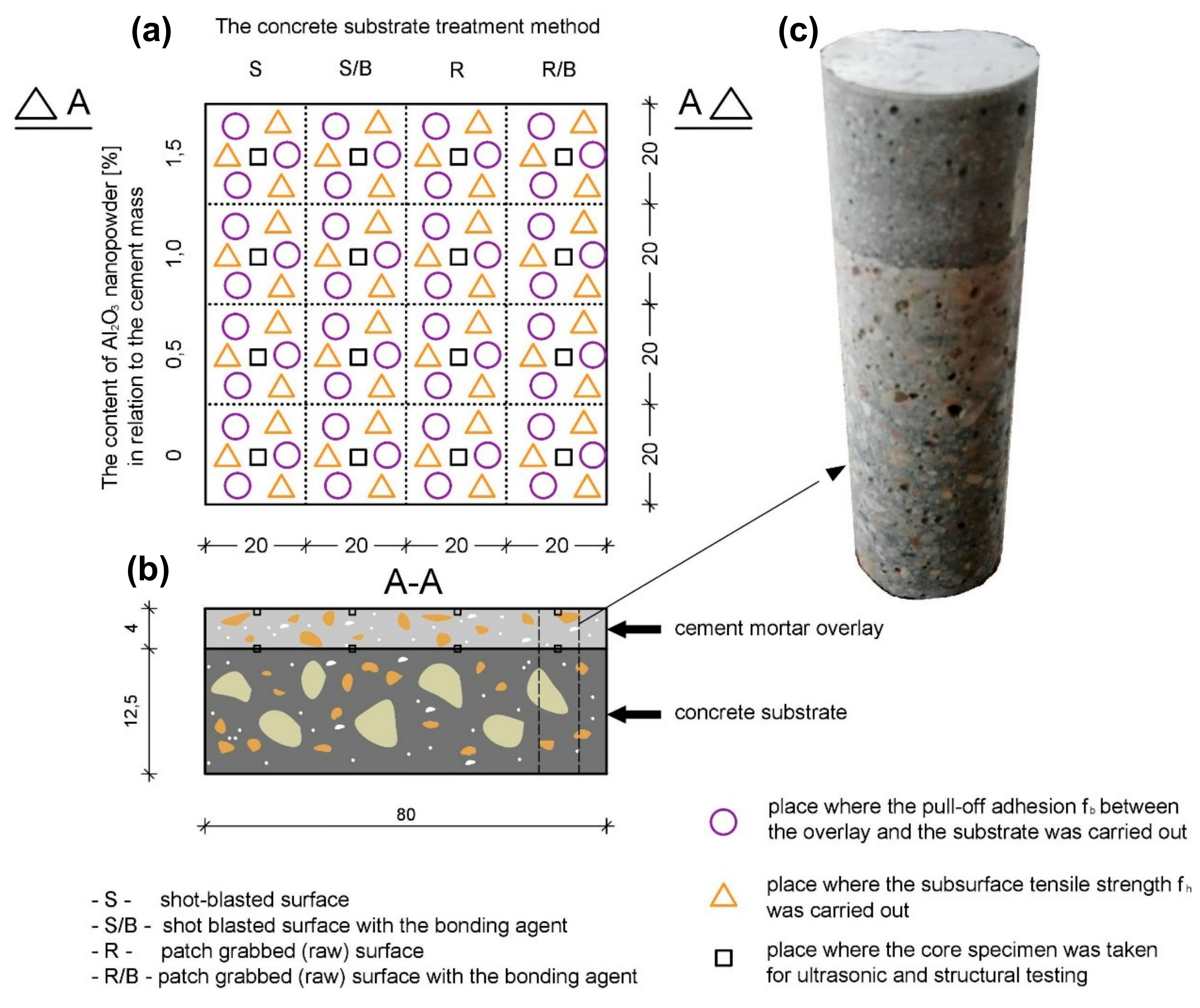
The tests were carried out on a model element with dimensions of 800 × 800 mm2. This element was made of cement-based composites: an overlay made of cement mortar and a substrate made of concrete. The total thickness of this element was equal to 165 mm (Figure 1). The overlay of the element had a thickness of 40 mm. The thickness of the substrate was equal to 125 mm.
The substrate was made of concrete, with a water-cement ratio equal to 0.47. The following materials were used to make the substrate (per 1 m3): 352.0 kg of Portland cement type CEM II A-LL 42.5 R (Cement Hranice, Italian Buzzi Unicem group, Hranice, Czech Republic); 165 kg of water; 40 kg of fly ash (Zespół Elektrociepłowni Wrocławskich “Kogeneracja S.A”, Wrocław, Poland); 724.4 kg of fine aggregate with a bulk density of 2.62 g/cm3 (Mineral mine WIKA, Paniowice, Poland); and 1086.6 kg of coarse aggregate with a maximum size of grain equal to 8 mm and a bulk density of 2.60 g/cm3 (Mineral mine “Byczeń”, Byczeń, Poland). In order to obtain a consistency class S3 (slump from 100–150 mm) of the concrete mix, 2.0 L/m3 of polycarboxylate-based plasticizer was used (Sika, Wroclaw, Poland). The density of this plasticizer was equal to 1.07 g/cm3. The water-cement ratio was 0.5. The maturation conditions of the substrate were the ambient temperature equal to 20 ± 3 °C and the humidity equal to 60% ± 5%. This concrete composition is commonly used to make substrates in layered elements in civil engineering (such as for example floors). After that, the surface of the concrete substrate was divided into four parts (Figure 1). Each of the parts was treated in different ways, which allowed four types of surfaces with different morphology to be obtained:
- S—shot-blasted surface obtained after shot-blasting with removal of dust;
- S/B—shot-blasted surface obtained after shot-blasting with removal of dust and the application of the bonding agent;
- R—patch grabbed (raw) surface obtained after casting;
- R/B—patch grabbed (raw) surface obtained after casting and the application of the bonding agent.
As the bonding agent, the ready-made mix based on synthetic resin (Weber PRIMO, Saint—Gobain Construction, Polska sp. z o.o., Warsaw, Poland) was applied. The bonding agent was applied on the surface of the substrate 4 h before casting the material of cement mortar used to make the overlay.
2.2. Mix Design of the Cement Mortar Used to Make the Overlay and Its Preparation
In this research, Al2O3 nanopowder (Sigma Aldrich, Poznan, Poland); Portland cement type CEM I 42.5 R with a bulk density of 1.106 g/cm3 containing 64.07% CaO, 19.98% SiO2, 4.95% Al2O3, 2.66% Fe2O3, 1.45% MgO, 0.73% K2O and 0.18% Na2O (Cementownia Górażdże Cement S.A. Heidelberg Cement Group, Górażdże, Poland); fine aggregate (sand) with a bulk density of 1.497 g/cm3 (mineral mine “Margo”, Mietkow, Poland); and polycarboxylate-based superplasticizer with a density of 1.080 g/cm³ (Sika, Wroclaw, Poland) were used to make the cement mortar in the proportions given in Table 1. The water-binder ratio for this mortar was equal to 0.3. The mixing procedure was as follows. The superplasticizer was added to the mixing. Then, Al2O3 nanopowder was added to the water and mix. Next the cement was added and mixed for 45 s using the rotation speed equal to 140 rpm (automatic mixer was used). Then sand was added and all was mixed for another 45 s using the same rotation speed. After that, the mix was mixed again for 18 s using the rotation speed equal to 285 rpm. After casting the cement mortar used to make the overlay, the maturation conditions were 21 ± 1 °C and 60% ± 5% humidity.
2.3. Determination of the Particle Size Distribution of Nanopowder Using Transmission Electron Microscopy (TEM)
The morphology of the Al2O3 nanopowder was examined with transmission electron microscopy (TEM) imaging using a Hitachi H-800 electron microscope (Hitachi, Tokyo, Japan). The powder was suspended in deionized water and macroscopic aggregates were ultrasonically partitioned for 1 s. The solution was immediately put on the standard carbon-on-copper supporting grids with a volume of 4 µL, drained of most liquid with filtering paper, then air dried for 1 h. Observations were made in standard bright-field mode, using an accelerating voltage of 150 kV and an EMSIS Quemesa CCD camera (EMSIS GmbH, Muenster, Germany).
2.4. Determination of the Consistency and Bulk Density of Fresh Mortars
Before laying the cement mortars used to make the overlay, their consistency was determined using a Novikow cone (MERAZET S. A., Poznań, Poland) according to [61]. The fresh mortar was placed in the measuring vessel and the metal cone was placed over the mortar surface (the vertex of the cone touched the surface) Then the metal cone was falling vertically for 10 s. After this time, the measurements were taken from the scale on the side surface of the cone. The measurement was repeated three times. In order to determine the bulk density of the fresh mortar according to standard [62], the fresh mortar was placed in the mold with specific volume and mechanically compacted and weighted. Then the bulk density was calculated. The measure of bulk density was taken three times. The setting times of fresh mortar were carried out using Vicat apparatus (MERAZET S. A., Poznań, Poland) according to standard [63].
2.5. Determination of the Mechanical Properties and Porosity of Hardened Cement Mortars
According to [64], 6 samples with size of 40 × 40 × 160 mm3 were concreted from each mix in order to determine the mechanical properties and porosity of hardened cement mortars. Among others, the total porosity p, the compressive strength fc and flexural strength fct were determined. The samples were stored at 21 ± 1 °C and humidity up to 90% and tested after 28 days. First, flexural strength tests were carried out on six samples with dimensions 40 × 40 × 160 mm3. Then 12 halves of these samples were used for compressive strength tests (6 samples with dimensions 40 × 40 × 80 mm3) and to determine the total porosity of hardened mortars (6 samples with dimensions 40 × 40 × 80 mm3). The total porosities p, were determined using a Le Chatelier volume vessel according to Equation (1):
—density (kg/cm3), —bulk density (kg/cm3).
2.6. Determination of the Pull-Off Adhesion of the Cement Mortars Used to Make the Overlays to the Concrete Substrate
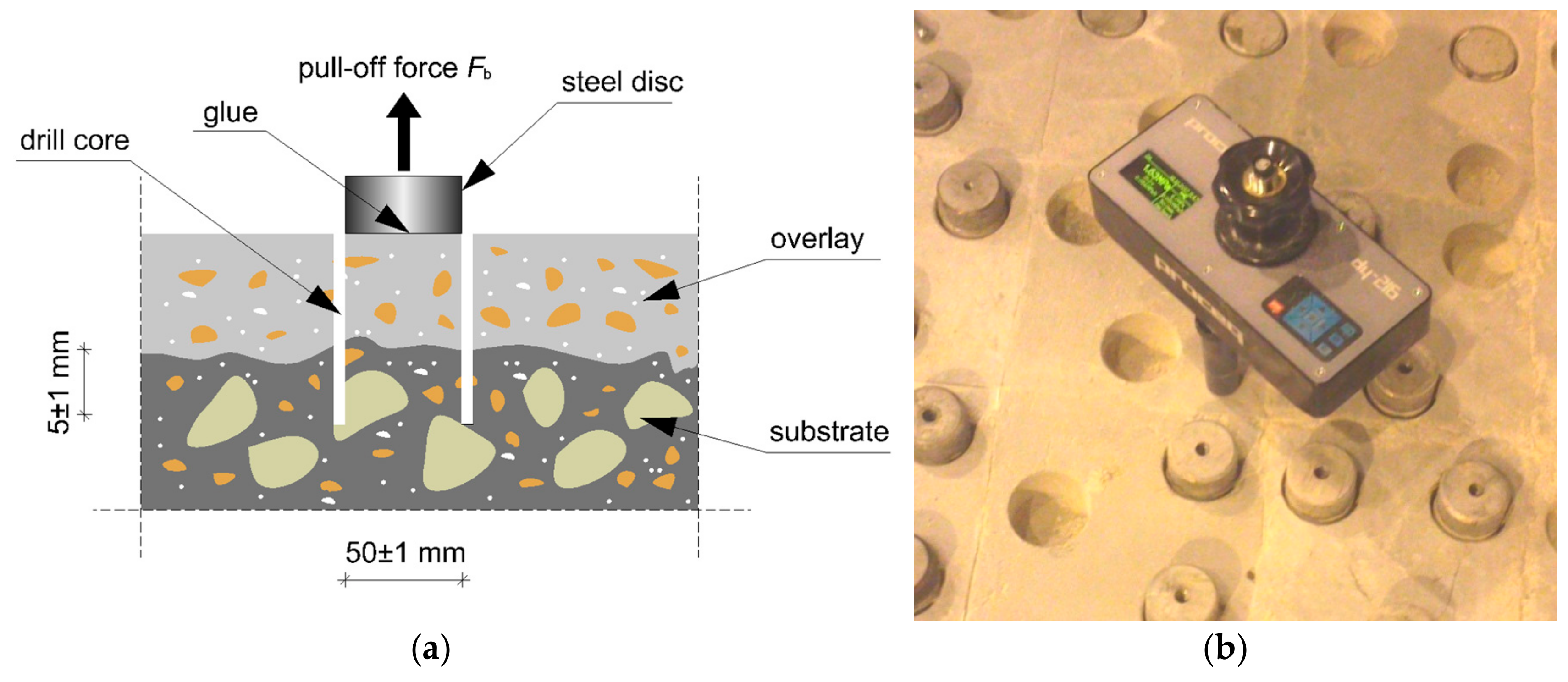
After 28 days, pull-off adhesion fb tests were carried out using the pull-off method according to [65]. On Figure 2 the scheme of this method has been presented. The procedure is as follows: the drill of the core in the cement mortar is used to make the overlay with a diameter Df = 50 mm and 5 mm. below overlay depth is performed, then the steel disc is glued to the overlay. Next, the steel disc is pulled off the substrate together with pulling off strength measuring. The loading rate should be equal to 0.05 MPa/s. The pull-off adhesion fb between the cement mortar used to make the overlay and the concrete substrate was calculated according to Equation (2):
—failure force (N), —the diameter of the core (m).
2.7. Determination of the Course of the Longitudinal Velocity of the Ultrasonic Wave along the Thickness of the Cement Mortar Used to Make the Overlay
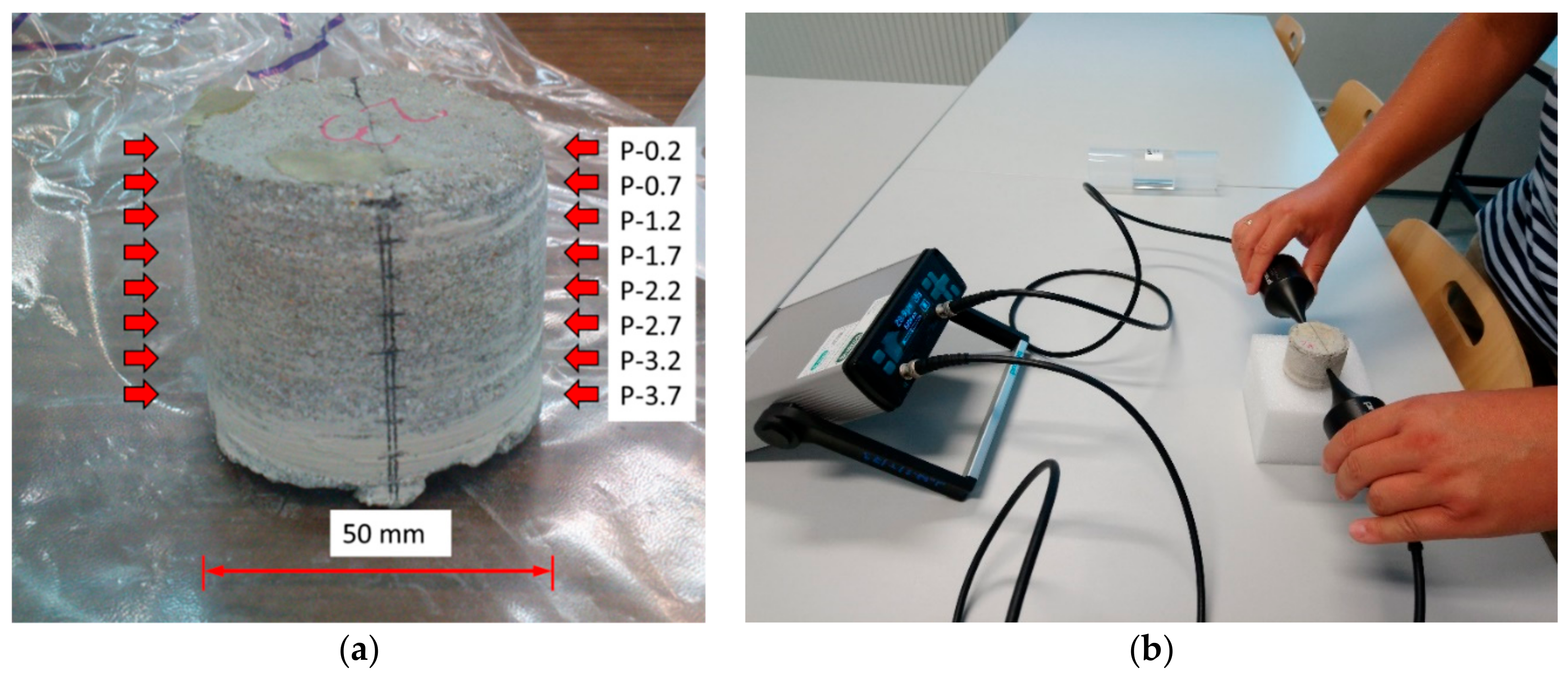
From each mortar, one core sample with a diameter of 50 mm was taken in order to determine the course of the longitudinal velocity of the ultrasonic wave cL along the thickness of the cement mortar used to make the overlay. Measuring points were marked on the lateral surfaces of these core samples at a spacing of 5 mm (Figure 3). Special ultrasound heads (Proceq AG, Schwerzenbach, Switzerland) with a frequency of 40 kHz were employed. These heads had a point contact with the test surface and are described in detail in [66]. Classical ultrasonic heads do not allow one to observe properly, the course of the longitudinal velocity of the ultrasonic wave cL along the thickness of the cement mortar [67,68,69,70,71]. Recently, this kind of head has been increasingly adopted to test cement-based materials [72,73].
2.8. Determination of the Abrasion Resistance of Cement Mortars
For each mortar, three samples measuring 71 × 71 × 71 mm3 were prepared in order to test their abrasion resistance according to [74]. The abrasion resistance was measured as volume loss or mass loss after 16 cycles of abrasion on Boehme (FORM+TEST Seidner&Co. GmbH, Riedlingen, Germany) wheel. The samples were fastened and loaded with a force of 294 ± 3 N (after each cycle the sample was turned at 90 degrees).
2.9. Determination of the Subsurface Tensile Strength and Subsurface Hardness of Cement Mortars
According to [65], the subsurface tensile strength fh of the cement mortar used to make the overlay was determined using the pull-off method on the surface of the overlay. According to [75], the subsurface hardness was determined using the sclerometric method. For subsurface hardness testing, the Schmidt hammer type N (Proceq AG, Schwerzenbach, Switzerland) was used. In each measuring point at least 9 measurements were taken.
2.10. Determination of the Microstructure of the Samples Using a Scanning Electron Microscope (SEM)
Then, from each mortar, 1 cubic sample of size 11 × 11 × 11 mm3 was taken from the subsurface zone of the cement mortar used to make the overlay. Consequently, 1 cubic sample with the same dimensions was prepared from the interphase zone between the cement mortar used to make the overlay and the concrete substrate. These samples were used for microstructural tests using a scanning electron microscope (SEM, JEOL, Tokyo, Japan). The procedure of obtaining samples was as follows: first, the drill core with a diameter of 50 mm was created in samples (Figure 1). Then, cubic samples were cut using table diamond saw. In order to analyze the microstructure of mortars, the JEOL SEM model JSM-6610A (JEOL, Tokyo, Japan) was used. It was equipped with a tungsten cathode (Tungsten Hairpin Filament). A material contrast mode of the backscattered electron (BSE, JEOL, Tokyo, Japan) detector was applied. The BSE detector had an accelerating voltage equal to 20 kV and a beam current of 40 nA at the working distance of 10 mm. The method of segmentation of pores with cement paste is based on analysis of area segmented on BSE images at different threshold levels [76]. As the threshold level increases, the area inside the pores increases, followed by pixels near the pore boundary. When the threshold level reaches a critical level, there is a significant increase in volume segmented in the BSE image around the pores. This critical level can be assumed as a threshold level for pores. It can be determined on the cumulative grayscale histogram near the inflection of the cumulative curve as the intersection point between two straight lines.
3. Results and Analysis
3.1. The Particle Size Distribution of Nanopowder Using Transmission Electron Microscopy (TEM)
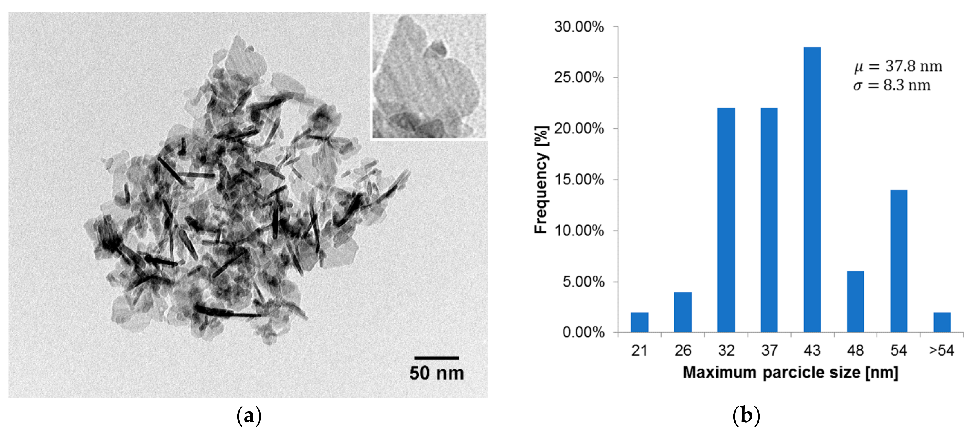
Figure 4 presents an image of the Al2O3 nanopowder particles, which was made using a TEM and the particle size distribution of Al2O3 nanopowder. Nanopowder containing 99.8% of Al2O3 with a mean particle size below 50 nm was used. The particle size distribution is based on 50 randomly chosen particles. The longest diagonal was assumed as particle size.
3.2. The Consistency and Bulk Density of Fresh Mortars
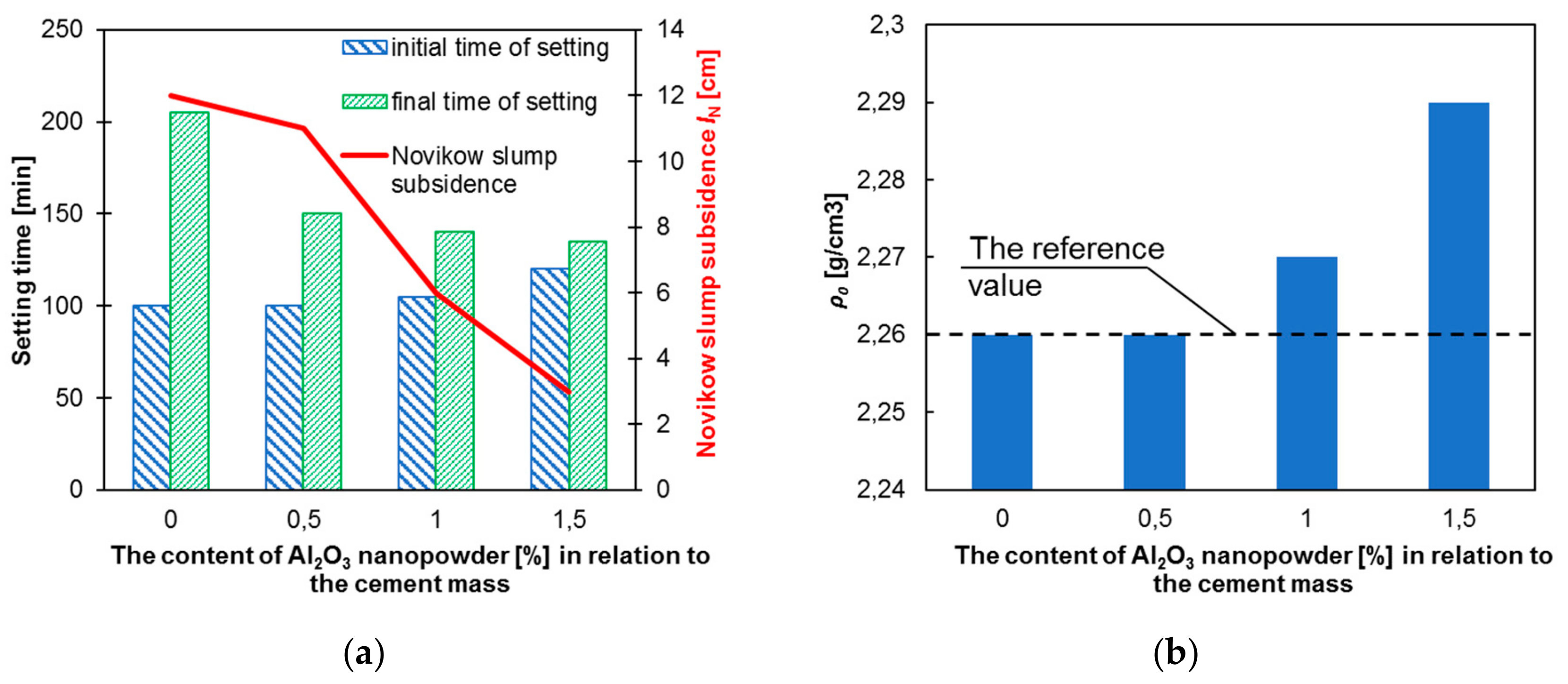
Figure 5 presents the dependence of Novikow slump test and setting times (Figure 5a), and the bulk density (Figure 5b) of fresh cement mortars on the content of Al2O3 nanopowder.
Figure 5a presents that the final setting time is shortened (maximum by about 34%) and the initial time is slightly longer (maximum by about 20%) together with the increase of content of Al2O3 nanopowder in the mortar. The probable reason the decrease of final setting time is faster hydration [76]. It should also be noted that as the content of Al2O3 nanopowder in the mortar increases, its consistency changes quickly (except for 0.5%). For the reference mortar, the Novikow cone dropped to 12 cm. For the addition of 1% of Al2O3 nanopowder, it was 6 cm and for 1.5% it was 3 cm. It can be seen from Figure 4b that the density of the fresh mortar increases with an increasing content of Al2O3 nanopowder in its composition. However, this increase is not greater than 1.5%.
3.3. The Mechanical Properties and Porosity of Hardened Cement Mortars
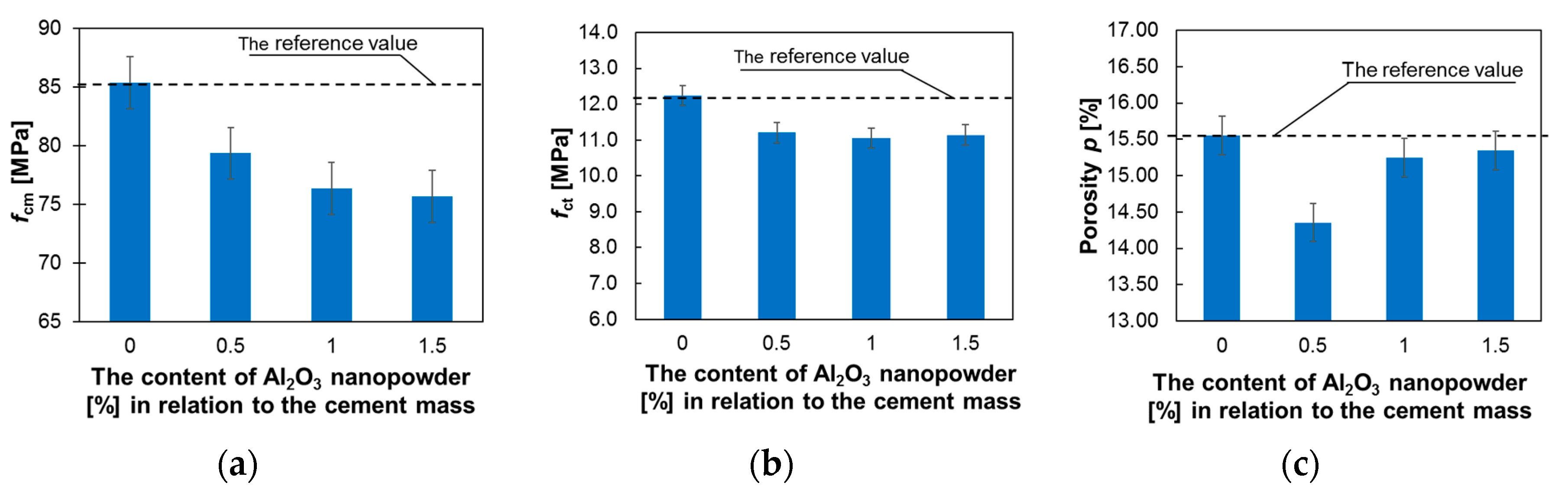
Figure 6 presents the results of testing the compressive strength, flexural strength and porosity of mortars differing in terms of their percentages of Al2O3 nanopowder.
Figure 5a presents that the compressive strength of all the tested mortars decreases with increasing amounts of Al2O3 nanopowder in their composition. For the addition of 0.5% Al2O3 nanopowder, this decrease became about 7%; for 1% it was about 10.6%; and for 1.5% it was about 11.4% compared to the reference mortar. In the literature there are papers which report that generally the addition of Al2O3 nanopowder can increase the compressive strength of mortars [77,78,79]; however, not at all cases. For example, some results presented, for example, those in papers [80,81,82], say that although the compressive strength of mortar with addition of Al2O3 nanopowder increased after three and seven curing days, the compressive strength after 28 days was lower than the value of reference mortar. The flexural strength was also reduced by approximately 10%, regardless of the nanopowder content (Figure 5b). For the addition of 1% and 1.5% nanopowder, the porosity is reduced to a maximum of about 2% in comparison with the reference mortar, and for the addition of 0.5% of Al2O3 nanopowder, the decrease of the porosity is about 7.7%. The possible reason for the decrease in mechanical properties could be related to low water/binder ratio of examined mortars (0.3). The addition of Al2O3 nanopowder decreases water/cement ratio and it can affect development of hydration.
3.4. The Pull-Off Adhesion of the Cement Mortar Used to Make the Overlay to the Concrete Substrate
Table 2 presents the test results of the pull-off adhesion fb of the cement mortar used to make the overlay to the concrete substrate. The results presented in Table 2 confirm the known fact that the application of a bonding agent prior to the application of the cement mortar used to make the overlay increases the pull-off adhesion fb. However, in this case, the mechanical treatment of the concrete substrate surface has a much greater impact on the increase of this adhesion. This is especially noticeable for the shot-blasted surface (increase by approximately 67% compared to the raw surface R). Such a great increase of adhesion presents how important the way substrate treatments and the morphology of their surface are handled before laying the cement mortar used to make the overlay. In paper [17] they referred that in the case of shot-blasted surface, the reason for the increase of adhesion is in increase of the effective surface area and the surface exposure of the coarse aggregate. For the shot-blasted surface S, the largest increase in pull-off adhesion fb was noted for the mortar with the addition of 0.5% of Al2O3 nanopowder. Table 2 also presents that the values of the coefficients of variation have a maximum value of about 7.13% for the raw, shot-blasted and shot-blasted surface with a bonding agent. On the other hand, for the raw surface with bonding agent, these values are several times higher (about 19% for the reference mortar and a maximum of about 24% in the mortars with the addition of Al2O3 nanopowder).
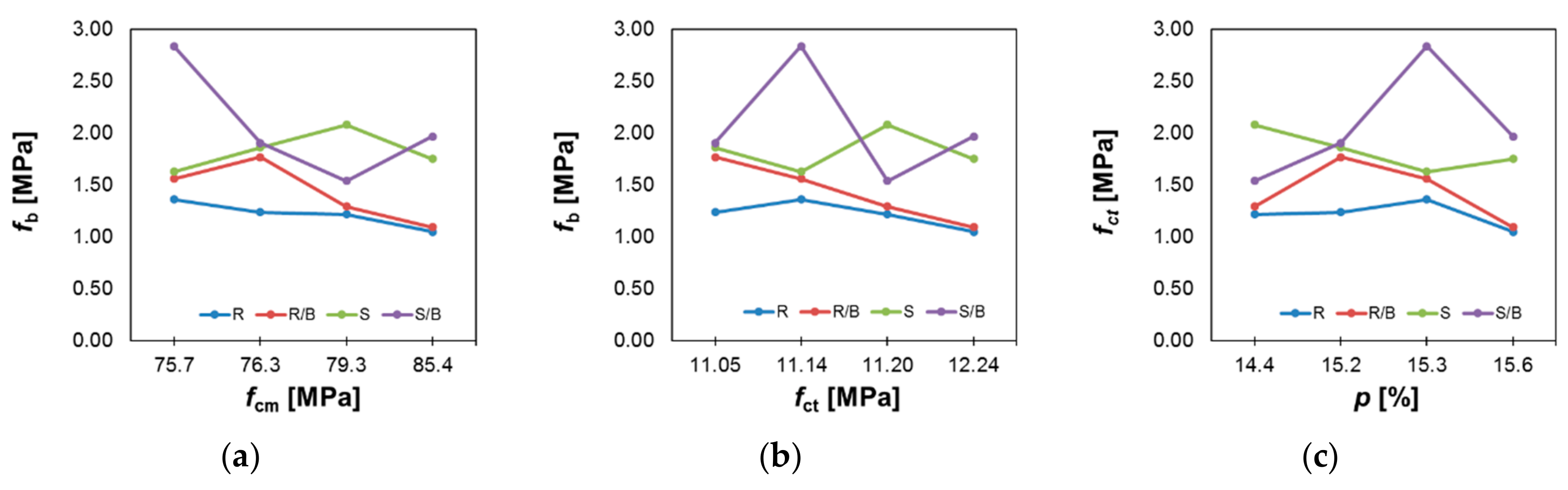
Diversely, Figure 7 presents the relationship between the pull-off adhesion fb values and the compressive strength fcm (Figure 7a), flexural strength fct (Figure 7b) and porosity p (Figure 7c) for the mortars.
Figure 7 presents that for the raw surface, and the raw surface with the bonding agent; the value of fb generally decreases as the compressive and flexural strength of the cement mortar used to make the overlay decreases. In this case, there is no clear relationship between porosity and adhesion. It can also be seen that the application of the bonding agent before applying the cement mortar used to make the overlay increases the fb value. For the shot-blasted surface and shot-blasted surface with a bonding agent, the fb values are higher than for the raw surfaces. In this case, there is no clear relationship between the values of fb and compressive strength, flexural strength and porosity. However, when considering only the mortars with the addition of Al2O3 nanopowder, it can be seen that with an increasing compressive strength, the fb decreases for the shot-blasted surface and for the shot-blasted surface with the bonding agent. It is also visible, that the fb values decrease with an increasing porosity for the shot-blasted surface and increase for the shot-blasted surface with the bonding agent.
3.5. The Course of the Longitudinal Velocity of the Ultrasonic Wave along the Thickness of the Cement Mortar Used to Make the Overlay
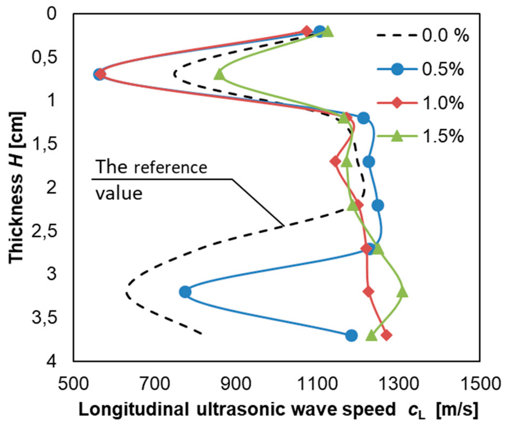
Figure 8 presents the course of the longitudinal velocity of the ultrasonic wave cL along the thickness H of the cement mortar used to make the overlay.
It can be concluded from Figure 8, that the values of the longitudinal velocity of the ultrasonic wave cL for the mortars with the addition of Al2O3 nanopowder (except mortar with addition of 0.5%) differ considerably from the values obtained for the mortar without Al2O3 nanopowder. That is especially visible in the lower section in Figure 8 (increase of the longitudinal velocity of the ultrasonic wave cL value by a maximum of about 200% for the mortars with a 1% and 1.5% addition). For the mortar with the addition of 0.5%, the course of ultrasonic velocity is similar but the increase by about 23% can still be seen. This is especially evident at a thickness of between 3 and 4 cm. In Figure 8, there are two peaks (in upper zone and bottom zone) which can be caused by patch grabbing the surface of the cement mortar used to make the overlay (the upper zone) and the wall effect [83]. These results are similar to those obtained by Stawiski [84,85], who presented that the quality of the cement mortar in the top zone of an overlay can be much worse than the quality of the cement mortar in the middle and bottom zones. Such great differences in the speed of ultrasonic wave may indicate an increase in the homogeneity of the mortar in the zone close to the interphase zone. Bearing the above in mind, in order to analyze the material microstructure in the interphase zone, samples of the mortar with the addition of 0.5% of Al2O3 nanopowder, which was laid on a concrete substrate prepared by shot-blasting, were taken.
3.6. The Abrasion Resistance of Cement Mortars
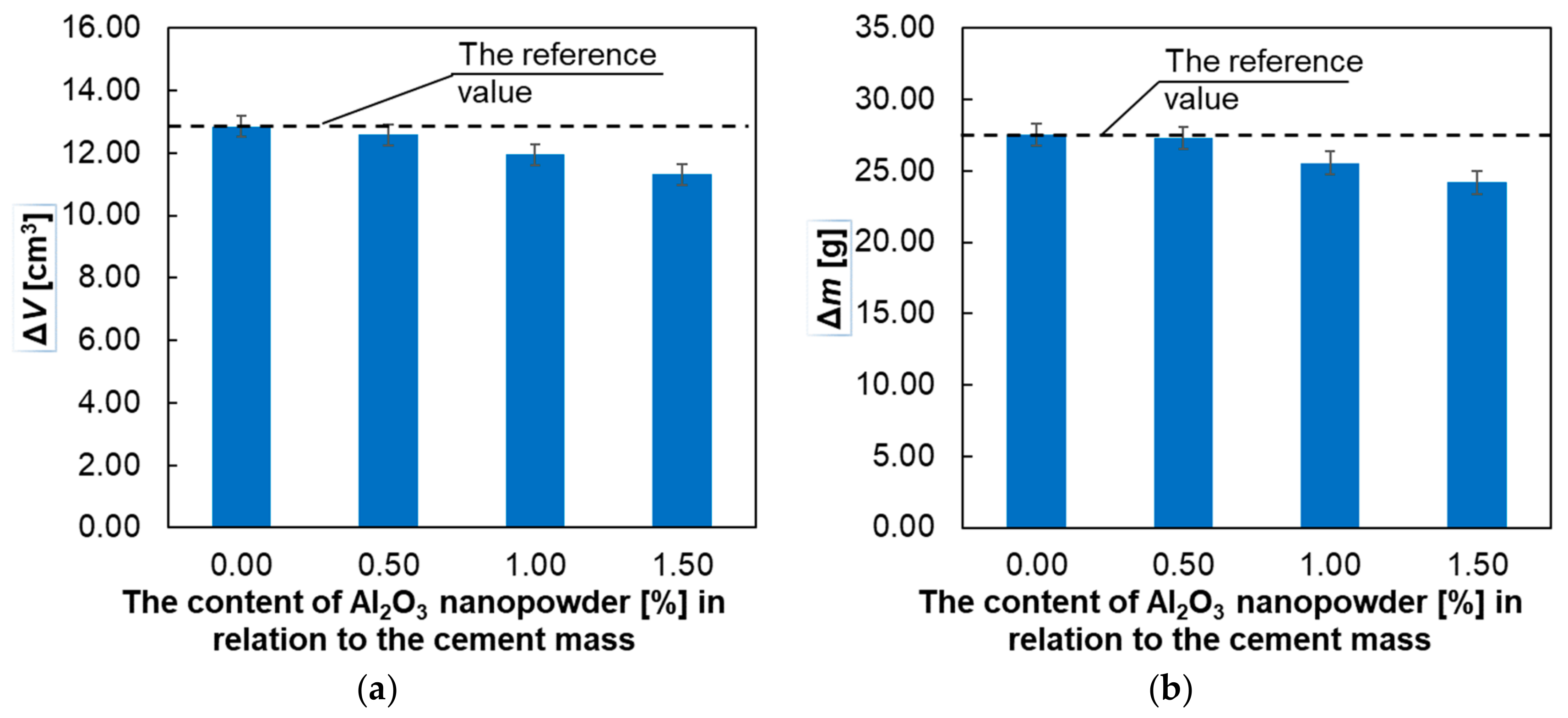
Figure 9 presents the relationship between the abrasion resistance of the mortars tested on the percentage of Al2O3 nanopowder.
Figure 9 shows that the abrasion resistance of all the mortars tested with the addition of Al2O3 nanopowder increased as the percentage of nanopowder increased. The maximum increase in abrasion resistance was observed for the addition of 1.5% Al2O3 nanopowder.
3.7. The Subsurface Tensile Strength and Subsurface Hardness of Cement Mortars
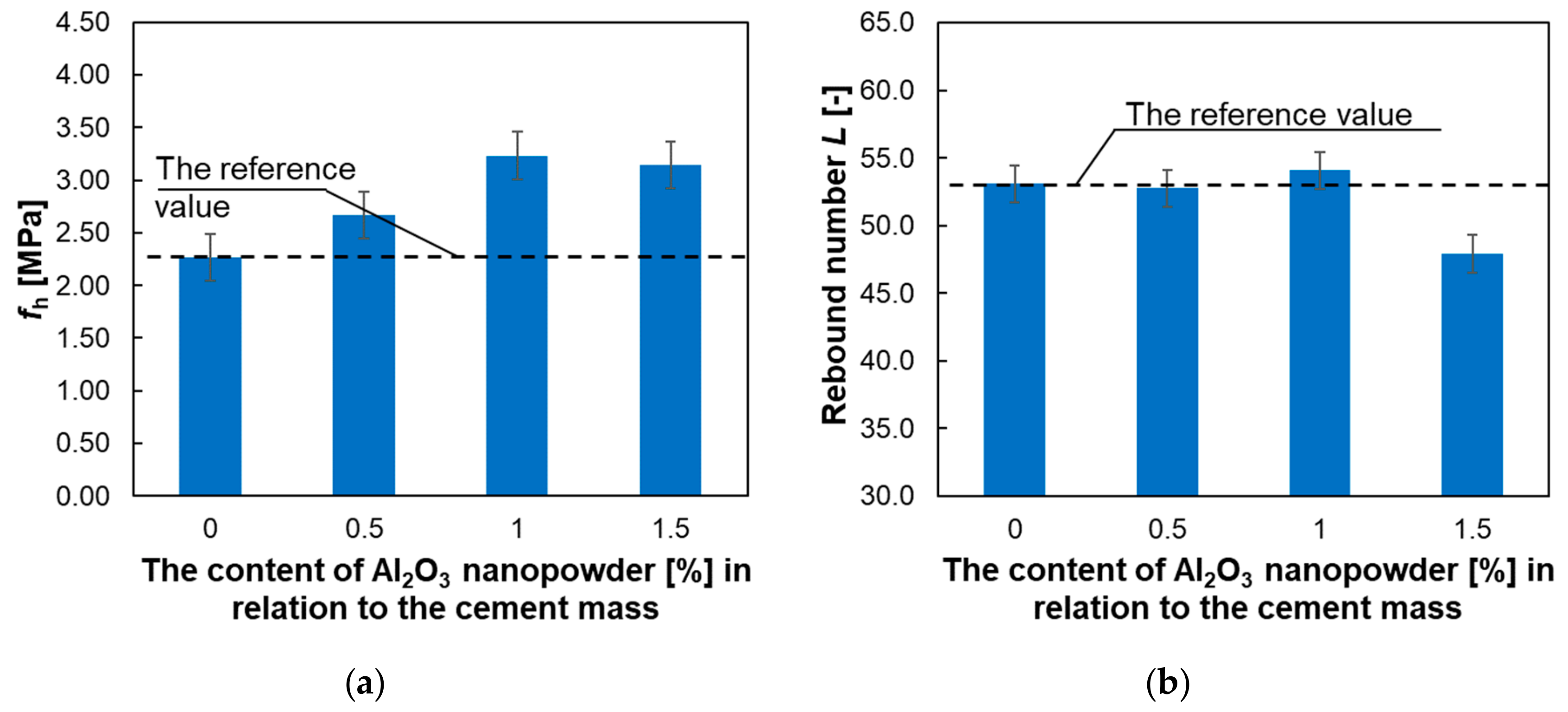
In turn, Figure 10 presents the dependence of subsurface tensile strength and the subsurface hardness of the cement mortar used to make the overlay, on the percentage of Al2O3 nanopowder.
Figure 10 shows that the addition of Al2O3 nanopowder increases the subsurface tensile strength of the cement mortar used to make the overlay. The maximum increase was about 61% and was observed for the addition of 1% of Al2O3 nanopowder. For the 0.5% of Al2O3 nanopowder, this increase was about 17%, and for the 1.5% of Al2O3 nanopowder it was about 42%. In turn, the hardness of the tested mortars assessed using the sclerometric method does not change significantly, except for the mortar with the addition of 1.5% of Al2O3 nanopowder, where the hardness decreased by about 10%.
3.8. The Microstructure of the Samples Using a Scanning Electron Microscope (SEM)
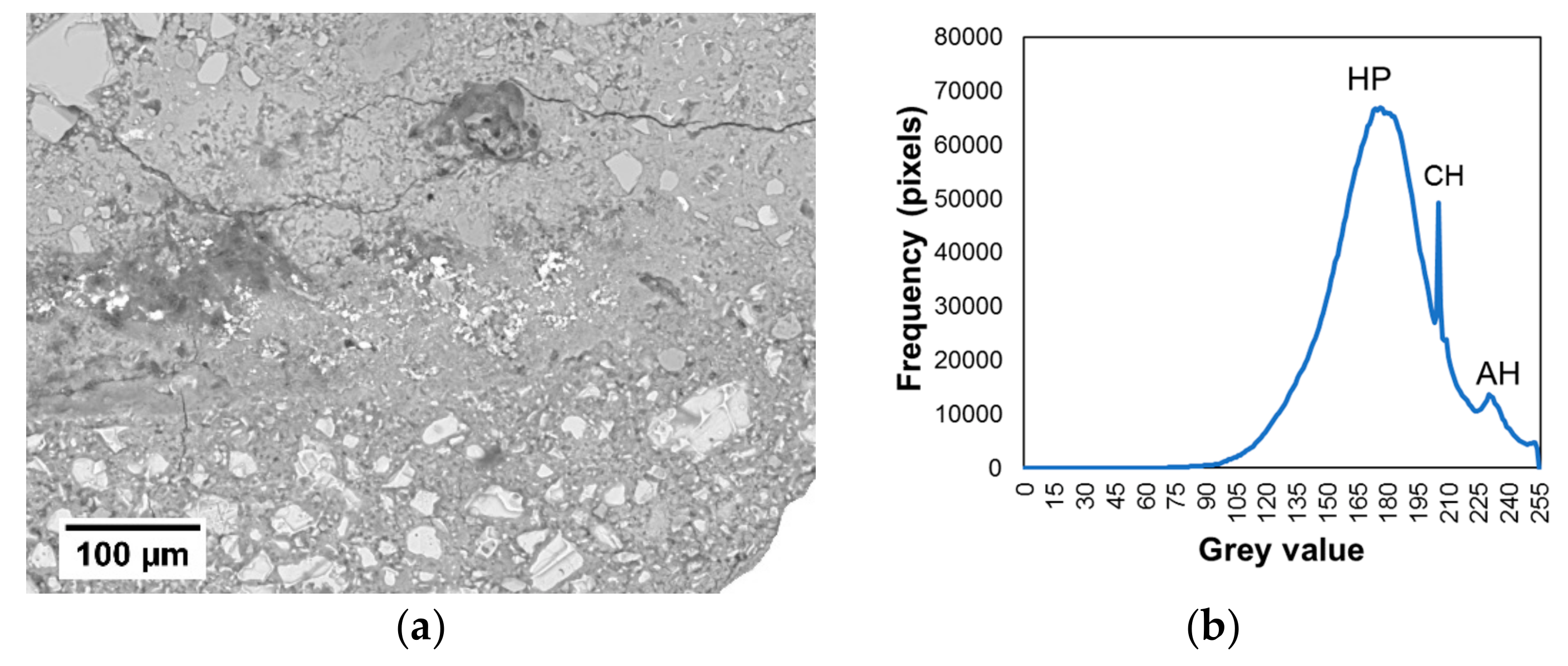
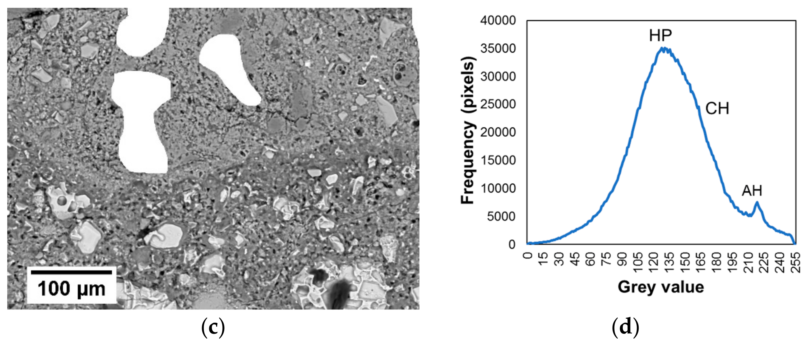
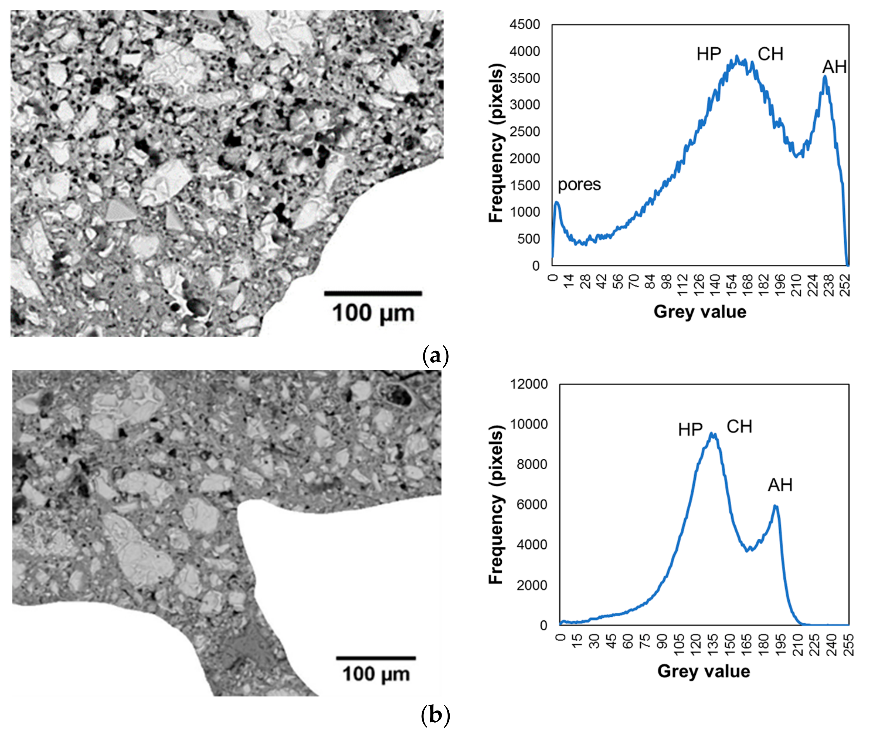
The results of tests using a SEM on the samples taken from the interphase zone are presented below. Gray scale histograms and the BSE images of the samples cut from the interphase zone of the cement mortar used to make the overlay with the concrete substrate made using a SEM are presented in Figure 11. Figure 11a refers to the reference mortar, and Figure 12b applies to the mortar with the addition of 0.5% of Al2O3 nanopowder. The analyzed areas of the 0.588 × 0.433 mm2 interphase zone are presented on the left. To analyze the cement matrix itself, the aggregate was cut out from both these images. This procedure was previously used in, e.g., [76]. The histograms presented in Figure 11 present three visible peaks showing pores, hydration products (HP) and anhydrous cement grains (AH), and one smaller peak which corresponds to the calcium hydroxide (CH).
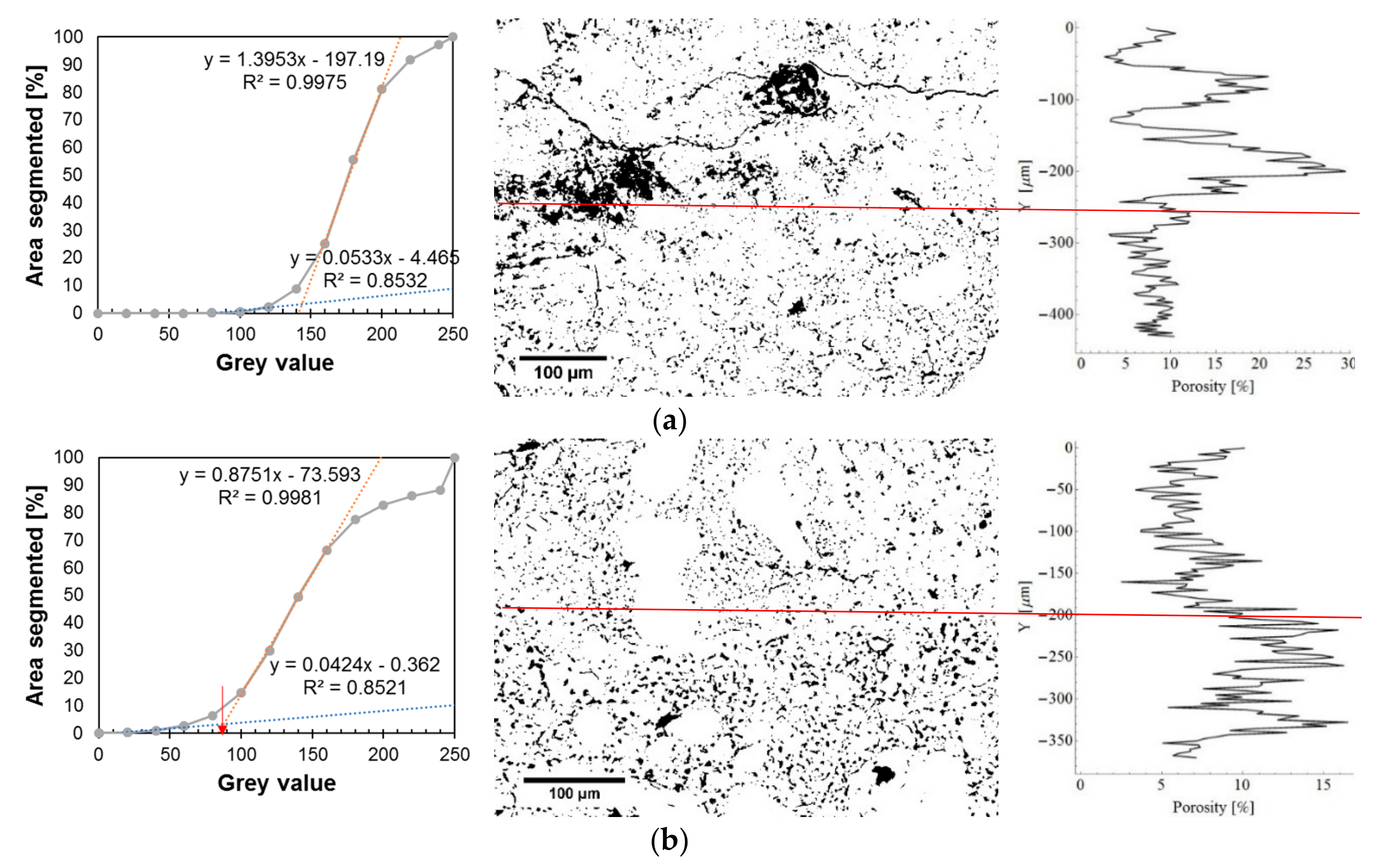
Alternatively, Figure 12 presents the cumulative gray scale histograms, images of segmented pores and charts of the fractional share of pores along the thickness. Figure 12a refers to the reference mortar, and Figure 12b applies to the mortar with the addition of 0.5% of Al2O3 nanopowder. The gray scale charts indicate the pore gray scale thresholds with a red arrow (following the procedure described in [76]). These values were used to generate images of the segmented pores, which are presented in the middle of the figure. On the right side of the figure, diagrams displaying the fractional share of pores along the thickness are presented. The red line indicates the center of the interphase.
Figure 11 and Figure 12 show that the mortar with the addition of 0.5% of Al2O3 nanopowder has a lower fractional share of pores compared to the reference mortar. The average value of the fractional share of pores for the reference mortar is about 10.18%, and for the mortar with the addition of nanopowder it is 8.38%. The use of 0.5% of Al2O3 nanopowder results in a reduction of the fractional share of pores in the interphase zone by about 18% compared to the reference mortar.
The results of tests using SEM on the samples taken from the subsurface zone of the cement mortar used to make the overlay are presented below. Figure 13 presents electron microscope (BSE) images and gray scale histograms.
The gray scale histogram for the reference mortar (Figure 13a) presents three large peaks and one much smaller peak. Large peaks are related to the pores, hydration products (HP) and anhydrous cement grains (AH), and a much smaller peak is related to the calcium hydroxide (CH). In turn, on the histogram presented in Figure 13b, the peak related to the pores is not clearly visible for the mortar with 0.5% of Al2O3 nanopowder. Figure 13 shows that the subsurface zone of the mortar with 0.5% of Al2O3 nanopowder is less porous compared to the reference mortar.
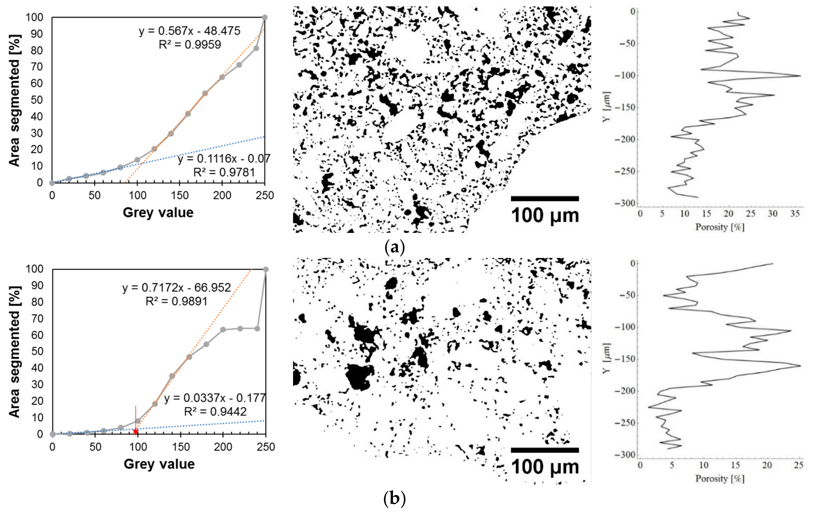
As a result of binarization, Figure 14 presents the cumulative gray scale histograms, images of segmented pores and charts of the fractional share of pores extracted from the BSE images presented in Figure 13. Figure 14 refers to the subsurface zone of the reference mortar used to make the overlay (Figure 14a) and for the mortar with 0.5% of Al2O3 nanopowder (Figure 14b). On the cumulative gray scale histograms, the pore gray scale threshold is marked with a red arrow (following the procedure presented in [76]). Then, the fractional fraction of pores was determined for the reference mortar (18.54%) and for the mortar with the addition of 0.5% of Al2O3 nanopowder (11.16%).
Figure 14 shows that the mortar with 0.5% of Al2O3 nanopowder has a smaller fractional share of pores at a thickness of 200 µm from the surface of the cement mortar used to make the overlay. The value of this fractional share of pores is about 15%, and for the reference mortar the value is about 20%. At a depth of less than 200 µm, the value of the fractional share of pores for both mortars decreases and is about 5% for the mortar with the addition of 0.5% of Al2O3 nanopowder and about 10% for the reference mortar.
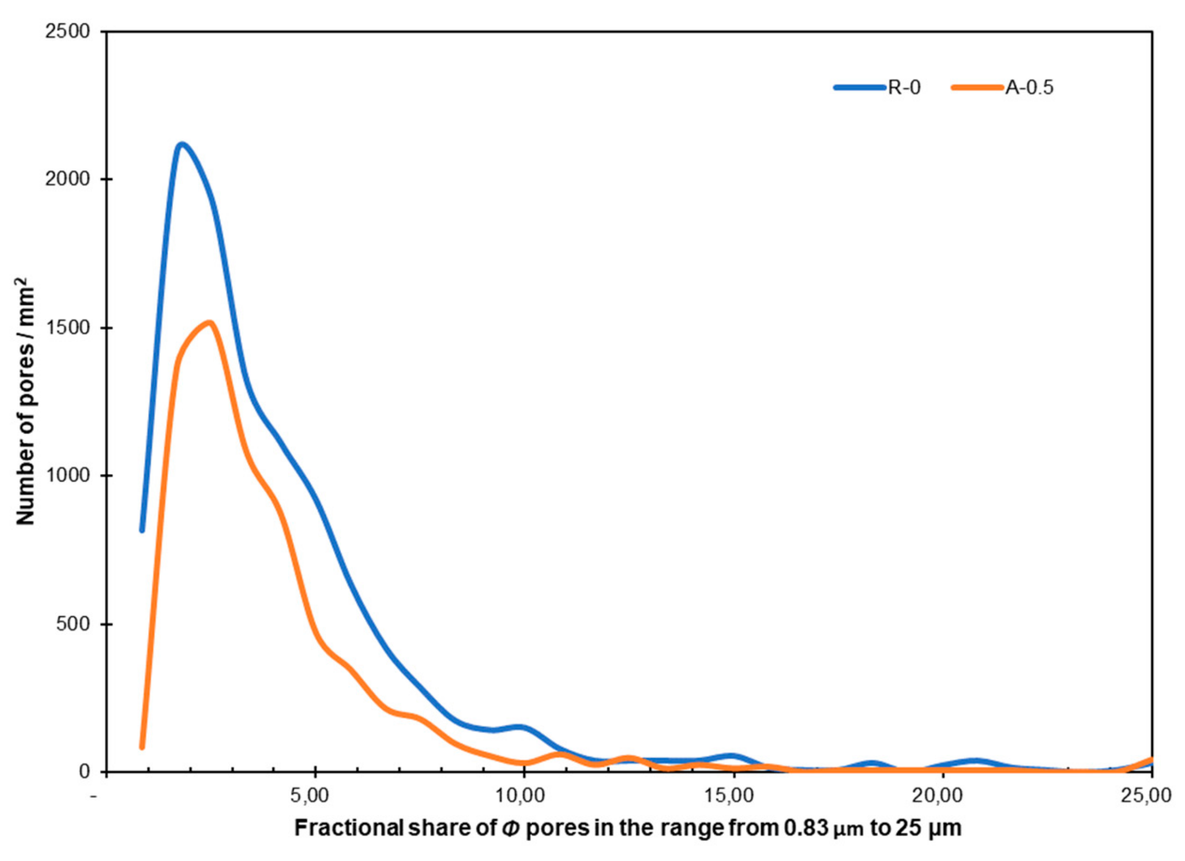
Figure 15 presents the fractional share of pores in the range of 0.83–25 μm/mm2 in the reference mortar and in the mortar with 0.5% of Al2O3 nanopowder.
Figure 15 shows that the matrix with 0.5% of Al2O3 nanopowder is less porous compared to the reference mortar. That is visible, especially for pores with sizes in the range of 0.83–10 µm. In both analyzed matrices, the largest number of pores was in the range of 2 to 3 µm (about 2100 pores per 1 mm2 in the reference mortar and about 1500 pores per 1 mm2 in the case of the mortar with the addition of 0.5% of Al2O3 nanopowder). The total fractional share of pores in the matrix was about 18.5% for the reference mortar and about 11.2% for the mortar with the addition of 0.5% of Al2O3 nanopowder.
4. Conclusions
The article focuses on the effect of applying aluminum oxide (Al2O3) nanopowder to cement mortar used to make the overlay, on the adhesion of this overlay to concrete substrate, and also its effect on the functional properties of the cement mortar used to make the overlay. The following conclusions cane be drawn:
- The studies conducted of setting times, tests using the Novikow cone and tests of the bulk density of the fresh cement mortars showed that, with an increasing content of Al2O3 nanopowder in the cement mortar, the consistency of the mixture deteriorates. The exception is the addition of 0.5% of Al2O3 nanopowder, for which the consistency of the mix is at a lower level when compared to the mortar without nanopowder in its composition. In addition, the increase in content of Al2O3 nanopowder, compared to the reference mortar, causes the shortening of the initial setting time and extending of the final setting time. It was found that the bulk density of fresh mortar is higher, together with an increase of the content of Al2O3 nanopowder. However, this was not the case for the addition of 0.5%, for which the density is at the same level in relation to the reference mortar.
- It was found that the mechanical properties and porosity of the hardened mortar do not depend on the addition of Al2O3 nanopowder. Only the addition of 0.5% of Al2O3 nanopowder decreases the porosity in comparison to the reference mortar without nanopowder in its composition. In turn, the addition of 0.5%, 1.0% and 1.5% of Al2O3 nanopowder results in a lower compressive and flexural strengths than for the reference mortar.
- The results obtained using the pull-off method show that the addition of 0.5% of Al2O3 nanopowder has a positive effect on the pull-off adhesion fb of the cement mortar used to make the overlay to the concrete substrate. It was shown that the addition of Al2O3 nanopowder considerably reduces the coefficient of variation and standard deviation of the values obtained of the pull-off adhesion fb. This was confirmed by ultrasonic tests, which presented that the addition of Al2O3 nanopowder in cement mortar has a very positive effect on the longitudinal wave speed cL at a distance of about 15 mm from the interphase between the cement mortar used to make the overlay and the concrete substrate. This was also confirmed by the research carried out using a scanning electron microscope (SEM), which proved that the reason for improving the adhesion is the fact that the mortar with 0.5% of Al2O3 nanopowder is less porous compared to the reference mortar.
- The results of the abrasion resistance tests were that when using 1.0% and 1.5% of Al2O3 nanopowder, the abrasion resistance of the cement mortar used to make the overlay increased in comparison with the reference mortar. It was also found that the mortar made with 0.5%, 1.0% and 1.5% of Al2O3 nanopowder had a lower subsurface tensile strength in relation to the reference mortar. On the other hand, the subsurface hardness of the cement mortar used to make the overlay, detected using the sclerometric method, does not depend on the addition of Al2O3 nanopowder. The most favorable results, in terms of lower abrasion resistance and higher subsurface tensile strength, are mainly brought about by the use of 0.5% of Al2O3 nanopowder. The studies performed using SEM confirmed that the reason for the improvement in abrasion resistance and subsurface tensile strength is the fact that the mortar with the addition of 0.5% of Al2O3 nanopowder is less porous than the reference mortar.
Author Contributions
Conceptualization, J.S.; Methodology, J.S.; Investigation, J.S.; Writing—original draft preparation, J.S.; Writing—review and editing, J.S. and Ł.S.; Supervision, Ł.S.
Funding
This research received no external funding.
Conflicts of Interest
The authors declare no conflict of interest.
References
- Czarnecki, L.; Emmons, P.H. Repair and Protection of Concrete Structures; CRC Press: Boca Raton, FL, USA, 2002. [Google Scholar]
- Król, M. Naprawy i wzmocnienia konstrukcji budowlanych. Przegląd Bud. 2009, 80, 30–36. [Google Scholar]
- Ściślewski, Z. Ochrona konstrukcji żelbetowych; Arkady: Warszawa, Poland, 1999. [Google Scholar]
- Raupach, M.; Büttner, T. Concrete Repair to EN 1504: Diagnosis, Design, Principles and Practice; CRC Press: Boca Raton, FL, USA, 2014. [Google Scholar]
- Czarnecki, L.; Łukowski, P.; Garbacz, A. Naprawa i Ochrona Konstrukcji z Betonu–Komentarz do PN-EN 1504; Wydawnictwo Naukowe PWN: Warszawa, Poland, 2017. [Google Scholar]
- Kosior-Kazberuk, M. Metody doboru materiałów do ochrony i napraw konstrukcji żelbetowych zgodnie z EN 1504. Zeszyty Naukowe Politechniki Białostockiej. Budownictwo 2007, 31, 151–161. [Google Scholar]
- Raupach, M. Concrete repair according to the new European standard EN 1504. In Concrete Repair, Rehabilitation and Retrofitting; Taylor & Francis: London, UK, 2006; pp. 6–8. [Google Scholar]
- Lukovic, M.; Ye, G.; Van Breugel, K. Reliable concrete repair: A critical review. In Proceedings of the 14th International Conference Structural Faults and Repair, Edinburgh, UK, 3–5 July 2012. [Google Scholar]
- Lukovic, M.; Ye, G. Effect of moisture exchange on interface formation in the repair system studied by X-ray absorption. Materials 2016, 91, 2. [Google Scholar] [CrossRef] [PubMed]
- Sadowski, Ł.; Mathia, T.G. Multi-scale metrology of concrete surface morphology: Fundamentals and specificity. Constr. Build. Mater. 2016, 113, 613–621. [Google Scholar] [CrossRef]
- Luković, M.; Ye, G.; Schlangen, E.; van Breugel, K. Moisture movement in cement-based repair systems monitored by X-ray absorption. Heron 2017, 621, 21. [Google Scholar]
- Luković, M.; Šavija, B.; Schlangen, E.; Ye, G.; van Breugel, K. A 3D lattice modelling study of drying shrinkage damage in concrete repair systems. Materials 2016, 97, 575. [Google Scholar] [CrossRef]
- Lukovic, M.; Schlangen, E.; Ye, G.; Savija, B. Impact of surface roughness on the debonding mechanism in concrete repairs. In Proceedings of the 8th International Conference on Fracture Mechanics of Concrete and Concrete Structures, Toledo, Spain, 10–14 March 2013. [Google Scholar]
- Garbacz, A.; Górka, M.; Courard, L. Effect of concrete surface treatment on adhesion in repair systems. Mag. Concr. Res. 2005, 571, 49–60. [Google Scholar] [CrossRef]
- Van Der Putten, J.; De Schutter, G.; Van Tittelboom, K. Surface modification as a technique to improve inter-layer bonding strength in 3D printed cementitious materials. Rilem Tech. Lett. 2019, 4, 33–38. [Google Scholar] [CrossRef]
- Balakrishnan, V.S.; Obrosov, A.; Kuke, F.; Seidlitz, H.; Weiß, S. Influence of metal surface preparation on the flexural strength and impact damage behaviour of thermoplastic FRP reinforced metal laminate made by press forming. Compos. Part B Eng. 2019, 173, 106883. [Google Scholar] [CrossRef]
- Sadowski, Ł.; Żak, A.; Hoła, J. Multi-sensor evaluation of the concrete within the interlayer bond with regard to pull-off adhesion. Arch. Civ. Mech. Eng. 2018, 18, 573–582. [Google Scholar] [CrossRef]
- Sadowski, Ł.; Krzywiński, K.; Michoń, M. The influence of texturing of the surface of concrete substrate on its adhesion to cement mortar overlay. J. Adhes. Accept. 2019, 1–14. [Google Scholar] [CrossRef]
- Krzywiński, K.; Sadowski, Ł. The effect of texturing of the surface of concrete substrate on the pull-off strength of epoxy resin coating. Coatings 2019, 92, 143. [Google Scholar] [CrossRef]
- Santos, D.S.; Santos, P.M.D.; Dias-da-Costa, D. Effect of surface preparation and bonding agent on the concrete-to-concrete interface strength. Constr. Build. Mater. 2012, 37, 102–110. [Google Scholar] [CrossRef]
- Xiong, G.; Luo, B.; Wu, X.; Li, G.; Chen, L. Influence of silane coupling agent on quality of interfacial transition zone between concrete substrate and repair materials. Cem. Concr. Compos. 2006, 28, 97–101. [Google Scholar] [CrossRef]
- Błaszczyński, T.; Jasiczak, J.; Ksit, B.; Siewczyńska, M. Aspects of bond layer role in concrete repairs. Arch. Civ. Mech. Eng. 2006, 6, 75–87. [Google Scholar] [CrossRef]
- Mohammadi, M.; Moghtadaei, R.M.; Ashraf Samani, N. Influence of silica fume and metakaolin with two different types of interfacial adhesives on the bond strength of repaired concrete. Constr. Build. Mater. 2014, 51, 141–150. [Google Scholar] [CrossRef]
- Kuo, W.T.; Liu, M.Y.; Juang, C.U. Bonding Behavior of Repair Material Using Fly-Ash/Ground Granulated Blast Furnace Slag-Based Geopolymer. Materials 2019, 1210, 1697. [Google Scholar] [CrossRef]
- Gomaa, E.; Gheni, A.A.; Kashosi, C.; ElGawady, M.A. Bond strength of eco-friendly class C fly ash based alkali-activated concrete to portland cement concrete. J. Clean. Prod. 2019, 235, 404–416. [Google Scholar] [CrossRef]
- Sabah, S.A.; Hassan, M.H.; Bunnori, N.M.; Johari, M.M. Bond strength of the interface between normal concrete substrate and GUSMRC repair material overlay. Constr. Build. Mater. 2019, 216, 261–271. [Google Scholar] [CrossRef]
- Zanotti, C.; Borges, P.H.; Bhutta, A.; Banthia, N. Bond strength between concrete substrate and metakaolin geopolymer repair mortar: Effect of curing regime and PVA fiber reinforcement. Cem. Concr. Compos. 2017, 80, 307–316. [Google Scholar] [CrossRef]
- Nunes, V.A.; Borges, P.H.; Zanotti, C. Mechanical compatibility and adhesion between alkali-activated repair mortars and Portland cement concrete substrate. Constr. Build. Mater. 2019, 215, 569–581. [Google Scholar] [CrossRef]
- El-Rakib, T.M.; Farahat, A.M.; El-Degwy, W.M.; Shaheen, H.H. Shear transfer parameters at the interface between old and new concrete. In Proceedings of the International Conference on Performance of Construction Materials in the New Millennium (ICPCM), Elmaarefa Printing House, Cairo, Egypt, 18–20 February 2003. [Google Scholar]
- Robayo-Salazar, R.; Jesús, C.; de Gutiérrez, R.M.; Pacheco-Torgal, F. Alkali-activated binary mortar based on natural volcanic pozzolan for repair applications. J. Build. Eng. 2019, 25, 100785. [Google Scholar] [CrossRef]
- Qin, J.; Qian, J.; You, C.; Fan, Y.; Li, Z.; Wang, H. Bond behavior and interfacial micro-characteristics of magnesium phosphate cement onto old concrete substrate. Constr. Build. Mater. 2018, 167, 166–176. [Google Scholar] [CrossRef]
- Sadowski, Ł.; Hoła, J. Wpływ wybranych kwarcowych dodatków mineralnych modyfikujących beton warstwy wierzchniej na jego zespolenie z podkładem betonowym. Bud. O Zoptymalizowanym Potencjale Energetycznym 2017, 119, 21–26. [Google Scholar] [CrossRef]
- Luković, M.; Šavija, B.; Dong, H.; Schlangen, E.; Ye, G. Micromechanical study of the interface properties in concrete repair systems. J. Adv. Concr. Technol. 2014, 129, 320–339. [Google Scholar] [CrossRef]
- Binici, H. Effect of crushed ceramic and basaltic pumice as fine aggregates on concrete mortars properties. Constr. Build. Mater. 2007, 216, 1191–1197. [Google Scholar] [CrossRef]
- Barnat-Hunek, D.; Łagód, G.; Fic, S.; Jarosz-Hadam, M. Effect of Polysiloxanes on Roughness and Durability of Basalt Fibres–Reinforced Cement Mortar. Polymers 2018, 104, 420. [Google Scholar] [CrossRef]
- Halicka, A.; Ogrodnik, P.; Zegardlo, B. Using ceramic sanitary ware waste as concrete aggregate. Constr. Build. Mater. 2013, 48, 295–305. [Google Scholar] [CrossRef]
- Felekoğlu, B.; Türkel, S.; Altuntaş, Y. Effects of steel fiber reinforcement on surface wear resistance of self-compacting repair mortars. Cem. Concr. Compos. 2007, 295, 391–396. [Google Scholar] [CrossRef]
- Giergiczny, Z. Dodatki mineralne–niezastąpione składniki współczesnego cementu i betonu. Mater. Bud. 2009, 3, 46–50. [Google Scholar]
- Golewski, G.L. A novel specific requirements for materials used in reinforced concrete composites subjected to dynamic loads. Compos. Struct. 2019, 223, 110939. [Google Scholar] [CrossRef]
- Golewski, G.L. An assessment of microcracks in the Interfacial Transition Zone of durable concrete composites with fly ash additives. Compos. Struct. 2018, 200, 515–520. [Google Scholar] [CrossRef]
- Kurdowski, W. Dodatki mineralne do cementu a trwałość betonu. Monografia 1991, 106, 109–120. [Google Scholar]
- Łukowski, P. Modyfikacja materiałowa betonu; Stowarzyszenie Producentów Cementu: Kraków, Poland, 2016. [Google Scholar]
- Karunarathne, V.K.; Paul, S.C.; Šavija, B. Development of Nano-SiO2 and Bentonite-Based Mortars for Corrosion Protection of Reinforcing Steel. Materials 2019, 1216, 2622. [Google Scholar] [CrossRef] [PubMed]
- Cai, Y.; Xuan, D.; Poon, C.S. Effects of nano-SiO2 and glass powder on mitigating alkali-silica reaction of cement glass mortars. Constr. Build. Mater. 2019, 201, 295–302. [Google Scholar] [CrossRef]
- Szymanowski, J. Evaluation of the adhesion between overlays and substrates in concrete floors: Literature survey, recent non-destructive and semi-destructive testing methods and research gaps. Buildings 2019, 9, 203. [Google Scholar] [CrossRef]
- Sanchez, F.; Sobolev, K. Nanotechnology in concrete—A review. Constr. Build. Mater. 2010, 24, 2060–2071. [Google Scholar] [CrossRef]
- Sikora, P.; Abd Elrahman, M.; Stephan, D. The Influence of nanomaterials on the thermal resistance of cement-based composites—A Review. Nanomaterials 2018, 87, 465. [Google Scholar] [CrossRef]
- Horszczaruk, E. Properties of cement-based composites modified with magnetite nanoparticles: A review. Materials 2019, 122, 326. [Google Scholar] [CrossRef]
- Czarnecki, L. Czy nanotechnologia to przyszłość betonu? Mater. Bud. 2007, 11, 4–5. [Google Scholar]
- Shah, S.P.; Hou, P.; Konsta-Gdoutos, M.S. Nano-modification of cementitious material: Toward a stronger and durable concrete. J. Sustain. Cem. Based Mater. 2016, 5, 1–22. [Google Scholar] [CrossRef]
- Yang, X.; Sun, L.; Huang, B.; Zhan, B.; Zhang, C.; Chu, Y.; An, D. Tuning the properties of functional adhesives with hybrid nanofillers for structural health monitoring. J. Adhes. 2019, 1–16. [Google Scholar] [CrossRef]
- Niewiadomski, P. Short overview of the effects of nanoparticles on mechanical properties of concrete. In Key Engineering Materials; Trans Tech Publications: Baech, Switzerland, 2015; Volume 662, pp. 257–260. [Google Scholar]
- Iskra-Kozak, W.; Konkol, J. Concrete nanomodification with selected nanoparticles. Czas. Inżynierii LądowejŚrodowiska I Archit. 2018, 65, 113–120. [Google Scholar] [CrossRef]
- Szymanowski, J.; Sadowski, Ł. Functional and adhesive properties of cement-based overlays modifies with amorphous silica nanospheres. J. Adhes. 2019, 1–22. [Google Scholar] [CrossRef]
- Stefaniuk, D.; Niewiadomski, P.; Musiał, M.; Łydżba, D. Elastic properties of self-compacting concrete modified with nanoparticles: Multiscale approach. Arch. Civ. Mech. Eng. 2019, 194, 1150–1162. [Google Scholar] [CrossRef]
- Chen, J.; Liang, C.; Li, B.; Wang, E.; Li, G.; Hou, X. The effect of nano-γAl2O3 additive on early hydration of calcium aluminate cement. Constr. Build. Mater. 2018, 158, 755–760. [Google Scholar] [CrossRef]
- Zhai, L.L.; Ling, G.P.; Wang, Y.W. Effect of nano-Al2O3 on adhesion strength of epoxy adhesive and steel. Int. J. Adhes. Adhes. 2008, 28, 23–28. [Google Scholar] [CrossRef]
- Phoo-ngernkham, T.; Chindaprasirt, P.; Sata, V.; Hanjitsuwan, S.; Hatanaka, S. The effect of adding nano-SiO2 and nano-Al2O3 on properties of high calcium fly ash geopolymer cured at ambient temperature. Mater. Des. 2014, 55, 58–65. [Google Scholar] [CrossRef]
- Silva, J.V.; Ismael, R.; Carmo, R.N.F.; Lourenço, C.; Soldado, E.; Costa, H.; Júlio, E. Influence of nano-SiO2 and nano-Al2O3 additions on the shear strength and the bending moment capacity of RC beams. Constr. Build. Mater. 2016, 123, 35–46. [Google Scholar] [CrossRef]
- Gupta, S.K.; Shukla, D.K.; Kaustubh Ravindra, D. Effect of nanoalumina in epoxy adhesive on lap shear strength and fracture toughness of aluminium joints. J. Adhes. 2019, 1–23. [Google Scholar] [CrossRef]
- PN-B-04500:1985. Zaprawy budowlane—Badania cech fizycznych i wytrzymałościowych. Available online: http://sklep.pkn.pl/pn-b-04500-1985p.html (accessed on 16 March 2019).
- EN 1015-6:2000. Metody badań zapraw do murów—Określenie gęstości objętościowej świeżej zaprawy. Available online: http://sklep.pkn.pl/pn-en-1015-6-2000p.html (accessed on 16 March 2019).
- EN 196-1: 2016. Methods of testing cement—Part 1: Determination of compressive strength. Available online: http://sklep.pkn.pl/pn-en-196-1-2016-07p.html (accessed on 16 March 2019).
- EN 13892-2: 2004. Methods of test for screed materials—Part 2: Determination of flexural and compressive strength. Available online: http://sklep.pkn.pl/pn-en-13892-2-2004p.html (accessed on 16 March 2019).
- EN, B. 1542—Products and Systems for the Protection and Repair of Concrete Structures-Test Methods-Measurement of Bond Strength by Pull-Off; British Standard Institution: London, UK, 1999. [Google Scholar]
- Gudra, T.; Stawiski, B. Non-destructive strength characterization of concrete using surface waves. Ndt E Int. 2000, 33, 1–6. [Google Scholar] [CrossRef]
- Ongpeng, J.M.; Oreta, A.W.; Hirose, S. Characterization of Damage Using Ultrasonic Testing on Different Types of Concrete. Mater. Eval. 2018, 7611, 1532–1541. [Google Scholar]
- Czarnecki, S. Ultrasonic Evaluation of the pull-off adhesion between added repair layer and a concrete substrate. In IOP Conference Series: Materials Science and Engineering; IOP: London, UK, 2007; Volume 245, p. 032037. [Google Scholar]
- Szymanowski, J.; Sadowski, Ł. Ultrasonic Pulse Velocity Evaluation of the Pull-Off Adhesion between Epoxy Resin and Concrete Substrate. In Key Engineering Materials; Trans Tech Publications: Baech, Switzerland, 2017; Volume 728, pp. 390–395. [Google Scholar]
- Szymanowski, J.; Sadowski, Ł. Adhesion assessment between concrete layers using the ultrasonic pulse velocity method. In Applied Mechanics and Materials; Trans Tech Publications: Baech, Switzerland, 2015; Volume 797, pp. 145–150. [Google Scholar]
- Ongpeng, J.M.C.; Oreta, A.W.C.; Hirose, S. Contact and Noncontact Ultrasonic Nondestructive Test in Reinforced Concrete Beam. Adv. Civ. Eng. 2018, 2018. [Google Scholar] [CrossRef]
- Michałek, J. Variation in Compressive Strength of Concrete across Thickness of Placed Layer. Materials 2019, 1213, 2162. [Google Scholar] [CrossRef] [PubMed]
- Skowroński, W.; Stawiski, B. Ultrasonic evaluation regarding the effects of biological corrosion of historical roof trusses. In MATEC Web of Conferences; EDP Sciences: Les Ulis, France, 2019; Volume 284, p. 07006. [Google Scholar]
- EN 13892-3:2005 Methods for Testing Materials for Undercoats—Part 3: Determination of Abrasion Resistance According to Bohme. Available online: http://sklep.pkn.pl/pn-en-13892-3-2015-02e.html (accessed on 16 March 2019).
- EN 12504-2:2013–Testing Concrete in Structures—Part 2: Nondestructive Testing—Determination of Rebound Number. Available online: http://sklep.pkn.pl/pn-en-12504-2-2013-03e.html (accessed on 16 March 2019).
- Wong, H.S.; Head, M.K.; Buenfeld, N.R. Pore segmentation of cement-based materials from backscattered electron images. Cem. Concr. Res. 2006, 366, 1083–1090. [Google Scholar] [CrossRef]
- Mohseni, E.; Miyandehi, B.M.; Yang, J.; Yazdi, M. A Single and combined effects of nano-SiO2, nano-Al2O3 and nano-TiO2 on the mechanical, rheological and durability properties of self-compacting mortar containing fly ash. Constr. Build. Mater. 2015, 84, 331–340. [Google Scholar] [CrossRef]
- Gowda, R.; Narendra, H.; Rangappa, D.; Prabhakar, R. Effect of nano-alumina on workability, compressive strength and residual strength at elevated temperature of Cement Mortar. Mater. Today Proc. 2017, 4, 12152–12156. [Google Scholar] [CrossRef]
- Paul, S.C.; van Rooyen, A.S.; van Zijl, G.P.; Petrik, L.F. Properties of cement-based composites using nanoparticles: A comprehensive review. Constr. Build. Mater. 2018, 189, 1019–1034. [Google Scholar] [CrossRef]
- Nazari, A.; Riahi, S. Improvement compressive strength of concrete in different curing media by Al2O3 nanoparticles. Mater. Sci. Eng. A 2011, 528, 1183–1191. [Google Scholar] [CrossRef]
- Li, Z.; Wang, H.; He, S.; Lu, Y.; Wang, M. Investigations on the preparation and mechanical properties of the nano-alumina reinforced cement composite. Mater. Lett. 2006, 603, 356–359. [Google Scholar] [CrossRef]
- Mohseni, E.; Tsavdaridis, K.D. Effect of nano-alumina on pore structure and durability of Class F Fly ash self-compacting mortar. Am. J. Eng. Appl. Sci. 2016, 9, 323–333. [Google Scholar] [CrossRef]
- Śliwiński, J. Wall effect—Essence of the phenomenon and the way of taking it into account in the concrete mix design. Cem. Lime Concr. 1998, 3, 151–154. [Google Scholar]
- Stawiski, B. The heterogeneity of mechanical properties of concrete in formed constructions horizontally. Arch. Civ. Met. Eng. 2012, 121, 90–94. [Google Scholar] [CrossRef]
- Stawiski, B. Ultradźwiękowe badania betonów i zapraw głowicami punktowymi. Prace Naukowe Instytutu Budownictwa Politechniki Wrocławskiej. Monografie 2009, 92, 154. [Google Scholar]
Figure 1.
Model element made of cement-based composites: (a) view from the top, (b) cross-section and (c) view of the core specimen for structural testing (description in the text).
Figure 1.
Model element made of cement-based composites: (a) view from the top, (b) cross-section and (c) view of the core specimen for structural testing (description in the text).

Figure 2.
The pull-off method: (a) the scheme and (b) the view of test stand.

Figure 3.
The ultrasonic method: (a) the arrangement of measuring points on a core sample for testing the longitudinal velocity of the ultrasonic wave cL along the thickness of the cement mortar used to make the overlay; (b) the view of the core sample during the test.
Figure 3.
The ultrasonic method: (a) the arrangement of measuring points on a core sample for testing the longitudinal velocity of the ultrasonic wave cL along the thickness of the cement mortar used to make the overlay; (b) the view of the core sample during the test.

Figure 4.
View of: (a) the transmission electron microscope (TEM) image of Al2O3 nanopowder particles; (b) the particle size distribution of Al2O3 nanopowder.
Figure 4.
View of: (a) the transmission electron microscope (TEM) image of Al2O3 nanopowder particles; (b) the particle size distribution of Al2O3 nanopowder.

Figure 5.
Test results of fresh cement mortars: (a) Novikow slump test and setting times; (b) bulk density.
Figure 5.
Test results of fresh cement mortars: (a) Novikow slump test and setting times; (b) bulk density.

Figure 6.
Test results of mechanical properties and porosity of hardened mortars: (a) compressive strength, (b) flexural strength and (c) porosity.
Figure 6.
Test results of mechanical properties and porosity of hardened mortars: (a) compressive strength, (b) flexural strength and (c) porosity.

Figure 7.
Relationship between the pull-off adhesion fb values and the values of: (a) compressive strength fcm, (b) flexural strength fct and (c) porosity p.
Figure 7.
Relationship between the pull-off adhesion fb values and the values of: (a) compressive strength fcm, (b) flexural strength fct and (c) porosity p.

Figure 8.
The results of the course of the longitudinal velocity of the ultrasonic wave cL along the thickness H of the cement mortar used to make the overlay.
Figure 8.
The results of the course of the longitudinal velocity of the ultrasonic wave cL along the thickness H of the cement mortar used to make the overlay.

Figure 9.
Test results of the abrasion resistance of the hardened mortars: (a) volume loss ΔV; (b) mass loss Δm.
Figure 9.
Test results of the abrasion resistance of the hardened mortars: (a) volume loss ΔV; (b) mass loss Δm.

Figure 10.
Test results of the cement mortars: (a) subsurface tensile strength fh; (b) subsurface hardness defined by the rebound number L obtained using the sclerometric method.
Figure 10.
Test results of the cement mortars: (a) subsurface tensile strength fh; (b) subsurface hardness defined by the rebound number L obtained using the sclerometric method.

Figure 11.
Exemplary backscattered electron (BSE) images of the samples cut from the interphase zone of the cement mortar used to make the overlay with the concrete substrate (a,c), which were made using a scanning electron microscope (SEM). Gray scale histograms (b,d). Figures (a,b) refer to the reference mortar without Al2O3 nanopowder and (c,d) refer to the mortar modified with 0.5% of Al2O3 nanopowder.


Figure 12.
Exemplary cumulative gray scale histograms, images of segmented pores and charts of the fractional share of pores along the thickness of the interphase zone for the mortar: (a) without Al2O3 nanopowder; (b) modified with the addition of 0.5% of Al2O3 nanopowder.
Figure 12.
Exemplary cumulative gray scale histograms, images of segmented pores and charts of the fractional share of pores along the thickness of the interphase zone for the mortar: (a) without Al2O3 nanopowder; (b) modified with the addition of 0.5% of Al2O3 nanopowder.

Figure 13.
Exemplary backscattered electron (BSE) images of the samples taken from the subsurface zone of the cement mortar used to make the overlay with the concrete substrate, which were made using scanning electron microscope (SEM); and gray scale histograms for the mortar: (a) without Al2O3 nanopowder; (b) modified with the addition of 0.5% Al2O3 nanopowder.

Figure 14.
Exemplary cumulative gray scale histograms, images of segmented pores and charts of the fractional share of pores along the thickness within the subsurface zone for the mortar: (a) without Al2O3 nanopowder; (b) modified with the addition of 0.5% of Al2O3 nanopowder.
Figure 14.
Exemplary cumulative gray scale histograms, images of segmented pores and charts of the fractional share of pores along the thickness within the subsurface zone for the mortar: (a) without Al2O3 nanopowder; (b) modified with the addition of 0.5% of Al2O3 nanopowder.

Figure 15.
The fractional share of pores in the range of 0.83–25μm/mm2 in the reference mortar and in the mortar with 0.5% of Al2O3 nanopowder.
Figure 15.
The fractional share of pores in the range of 0.83–25μm/mm2 in the reference mortar and in the mortar with 0.5% of Al2O3 nanopowder.


Table 1.
Mix designs of cement mortars used to make the overlays with the addition of aluminum oxide (Al2O3) nanopowder (per 100 g of sand).
Table 1.
Mix designs of cement mortars used to make the overlays with the addition of aluminum oxide (Al2O3) nanopowder (per 100 g of sand).
| Content of Al2O3 Nanopowder | Al2O3 Nanopowder | Cement type CEM I 42.5 R | Fine Aggregate (Sand) | Polycarboxylate-Based Superplasticizer | Water |
|---|---|---|---|---|---|
| (% of the mass of cement) | (g) | ||||
| 0 | 0 | 73.30 | 100.00 | 0.37 | 22.00 |
| 0.5 | 0.37 | 73.30 | 100.00 | 0.37 | 22.00 |
| 1.0 | 0.73 | 73.30 | 100.00 | 0.37 | 22.00 |
| 1.5 | 1.10 | 73.30 | 100.00 | 0.37 | 22.00 |
Table 2.
Test results of the pull-off adhesion fb of the cement mortar used to make the overlay to the concrete substrate.
Table 2.
Test results of the pull-off adhesion fb of the cement mortar used to make the overlay to the concrete substrate.
| Surface | Content of Al2O3 Nanopowder | Mean Values | Standard Deviation | Coefficients of Variation |
|---|---|---|---|---|
| (% of the Mass of Cement) | (MPa) | (-) | (%) | |
| R (Patch grabbed surface) | 0 | 1.05 | 0.07 | 6.67% |
| 0.5 | 1.22 | 0.04 | 3.07% | |
| 1.0 | 1.24 | 0.04 | 3.29% | |
| 1.5 | 1.36 | 0.03 | 2.42% | |
| R/B (patch grabbed with bonding agent) | 0 | 1.10 | 0.21 | 19.09% |
| 0.5 | 1.29 | 0.30 | 22.87% | |
| 1.0 | 1.77 | 0.42 | 23.54% | |
| 1.5 | 1.56 | 0.30 | 19.38% | |
| S (shot-blasted surface) | 0 | 1.75 | 0.05 | 2.65% |
| 0.5 | 2.08 | 0.08 | 4.08% | |
| 1.0 | 1.86 | 0.05 | 2.85% | |
| 1.5 | 1.63 | 0.06 | 3.68% | |
| S/B (shot-blasted surface with bonding agent) | 0 | 1.97 | 0.09 | 4.62% |
| 0.5 | 1.54 | 0.11 | 7.13% | |
| 1.0 | 1.91 | 0.11 | 5.65% | |
| 1.5 | 2.84 | 0.06 | 2.16% |
© 2019 by the authors. Licensee MDPI, Basel, Switzerland. This article is an open access article distributed under the terms and conditions of the Creative Commons Attribution (CC BY) license (http://creativecommons.org/licenses/by/4.0/).
Share and Cite
MDPI and ACS Style
Szymanowski, J.; Sadowski, Ł. The Development of Nanoalumina-Based Cement Mortars for Overlay Applications in Concrete Floors. Materials 2019, 12, 3465. https://0-doi-org.brum.beds.ac.uk/10.3390/ma12213465
AMA Style
Szymanowski J, Sadowski Ł. The Development of Nanoalumina-Based Cement Mortars for Overlay Applications in Concrete Floors. Materials. 2019; 12(21):3465. https://0-doi-org.brum.beds.ac.uk/10.3390/ma12213465
Chicago/Turabian StyleSzymanowski, Jacek, and Łukasz Sadowski. 2019. "The Development of Nanoalumina-Based Cement Mortars for Overlay Applications in Concrete Floors" Materials 12, no. 21: 3465. https://0-doi-org.brum.beds.ac.uk/10.3390/ma12213465
Note that from the first issue of 2016, this journal uses article numbers instead of page numbers. See further details here.