Wear Morphology on the Surfaces of CoCrMo Unicompartmental Knee Joint Endoprostheses as Elements of Metal–Metal Friction Nodes

 , , , , and
Abstract
:
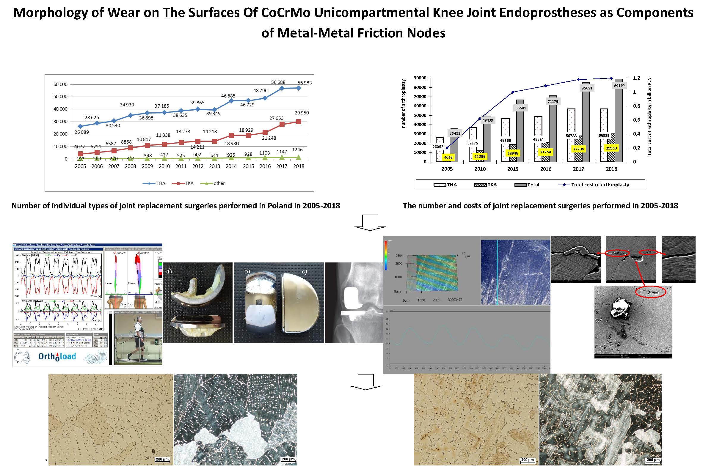
1. Introduction
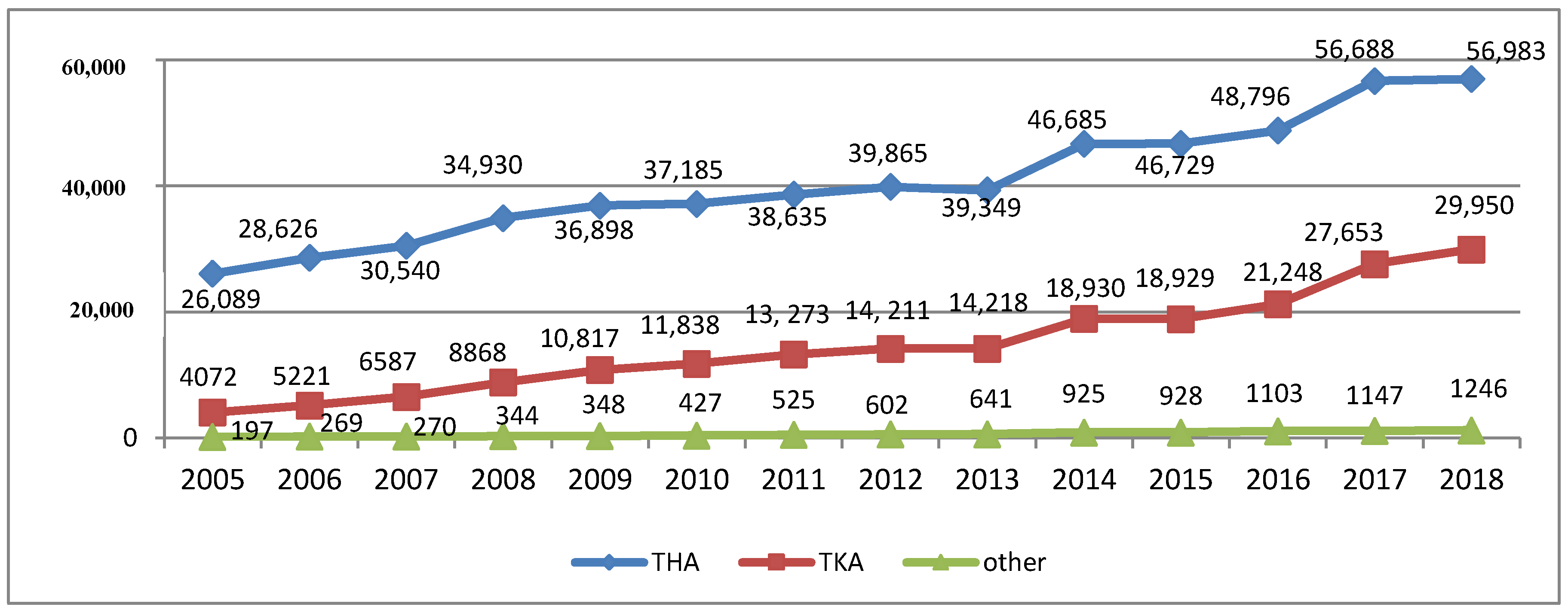
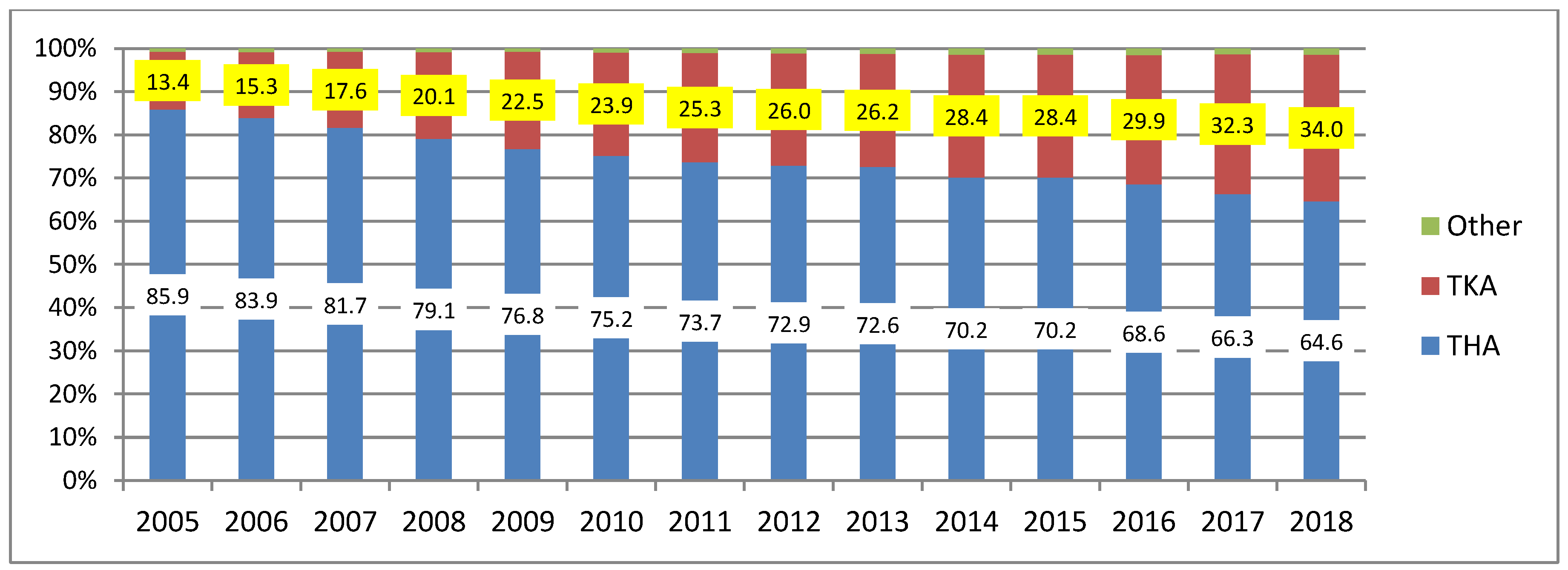
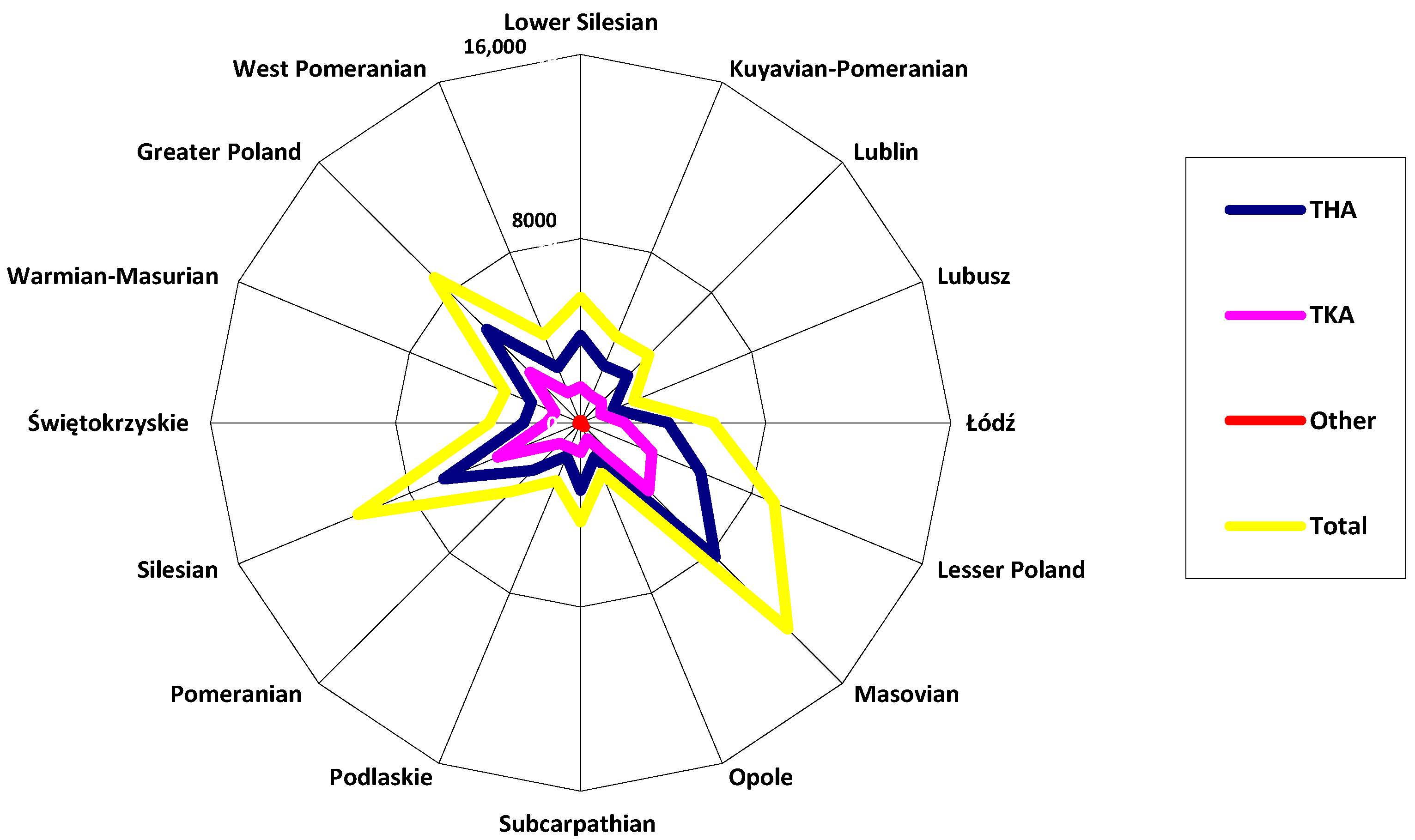
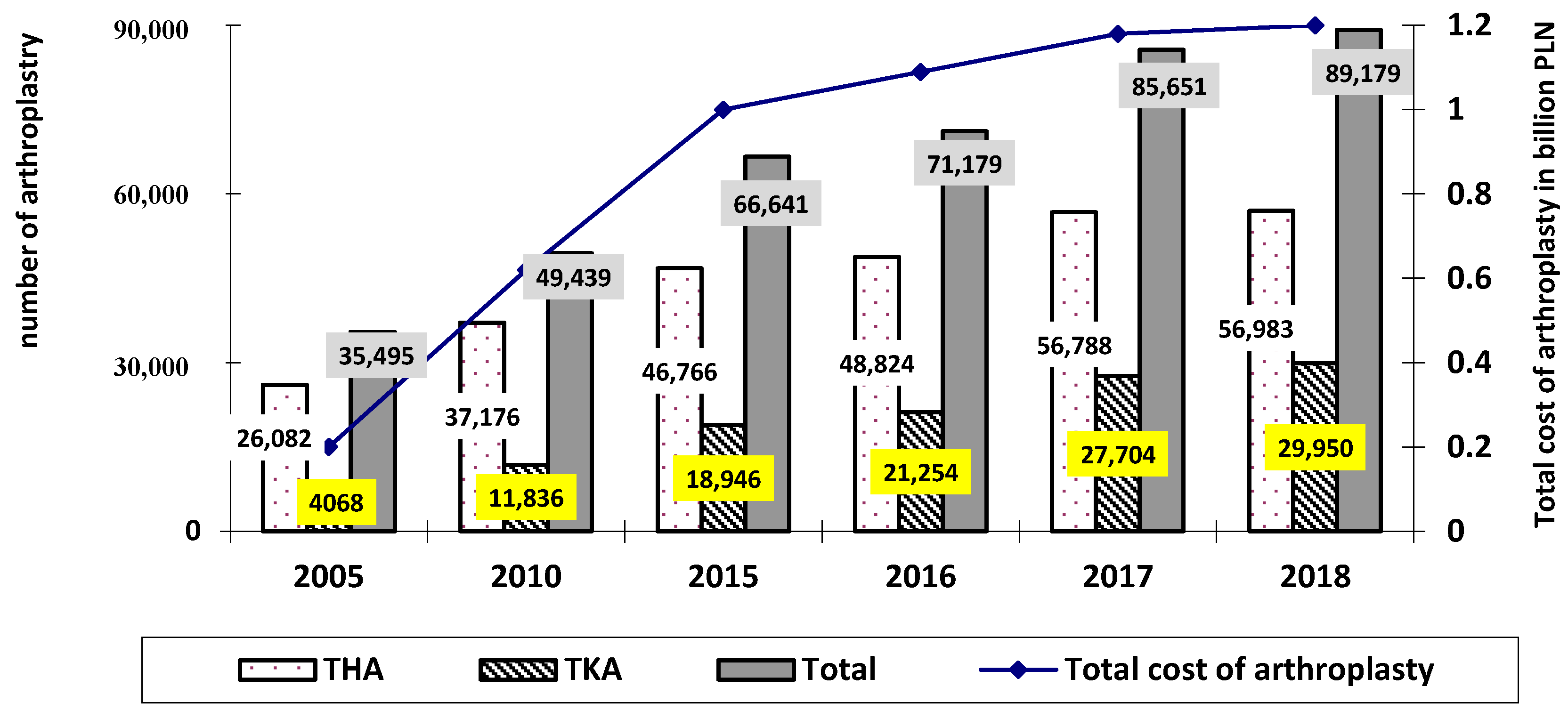
2. Statistical Evaluation of the Number of Surgeries and Costs of Joint Replacement in Poland
- 2020: THA—by 34% (to 498,000 replacements); TKA by 56% (to 1,065,000 replacements);
- 2025: THA—by 75% (to 652,000 replacements); TKA by 110% (to 1,272,000 replacements);
- 2030: THA—by 129% (to 850,000 replacements); TKA by 182% (to 1,921,000 replacements);
- 2040: THA—by 284% (to 1,429,000 replacements); TKA by 401% (to 3,416,000 replacements).
- (1)
- hip joint:
- cement alloplasty: in 2005: 9933–11,100 PLN (which translated into 2573–2876 EUR and 3047–3405 USD), in 2018: 10,000–11,700 PLN (which translated into 2325–2720 EUR and 2659–3112 USD);
- cementless arthroplasty: in 2005: 12,220–13,000 PLN (which translated into 3161–3368 EUR and 3742–3988 USD), in 2018: 13,000–23,000 PLN (which translated into 3023–5349 EUR and 3457–6117 USD);
- revision arthroplasty: in 2005: 20,835–24,095 PLN (which translated into 5398–6242 EUR and 6391–7391 USD), in 2018: 19,000–20,000 PLN (which translated into 4419–9070 EUR and 5053–5319 USD).
- (2)
- knee joint:
- cement arthroplasty: in 2005 13,590–17,456 PLN (which translated into 3521–4522 EUR and 4169–5355 USD); in 2018: 15,750–20,000 PLN (which translated into 3662–4651 EUR and 4189–5319 USD);
- revision arthroplasty: in 2005: 21,715–23,568 PLN (which translated into 5626–6106 EUR and 6661–7229 USD); in 2018: 12,500–20,000 PLN (which translated into 2907–4651 EUR and 3324–5319 USD).
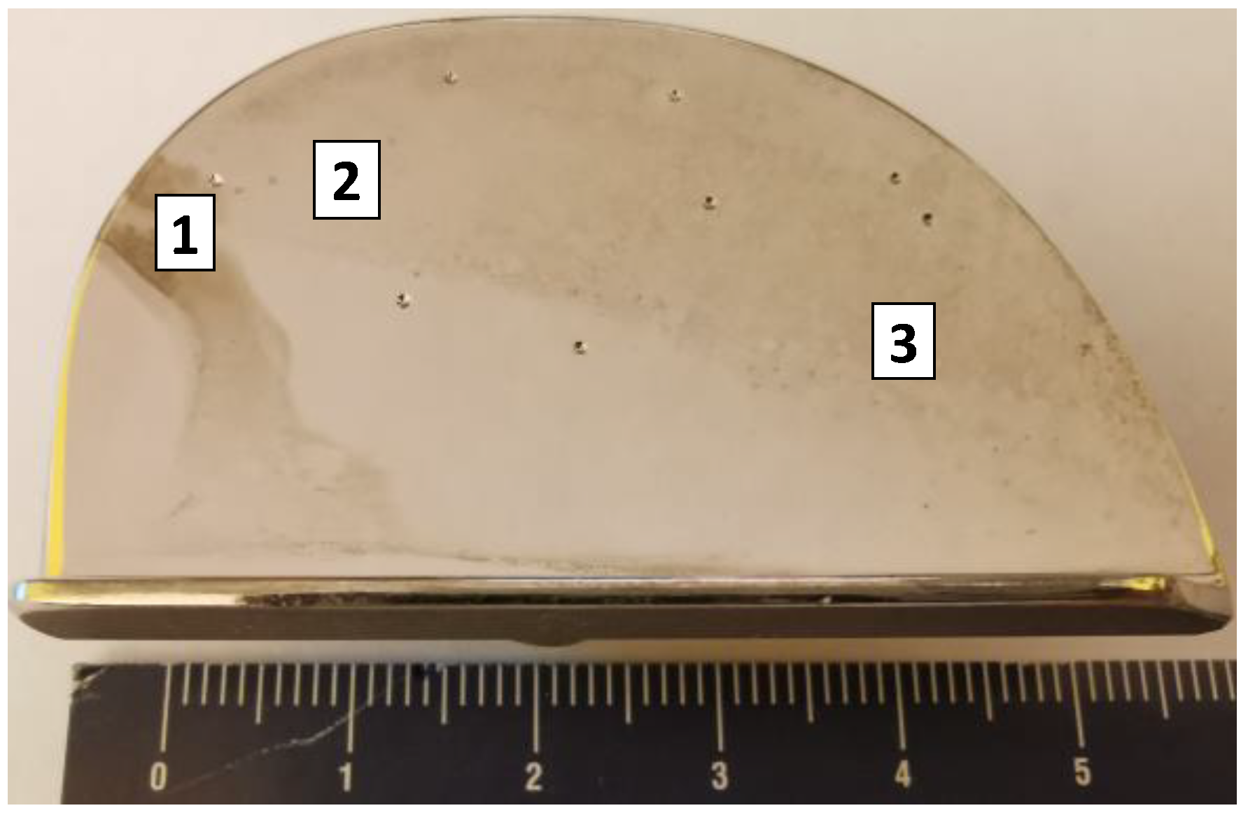
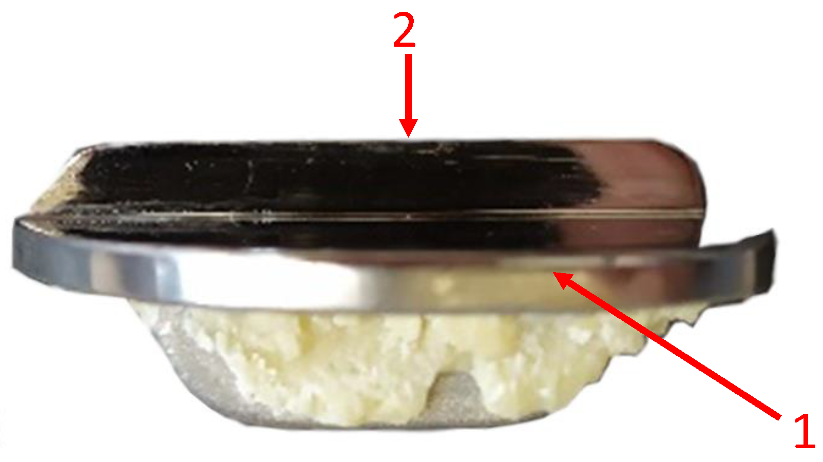
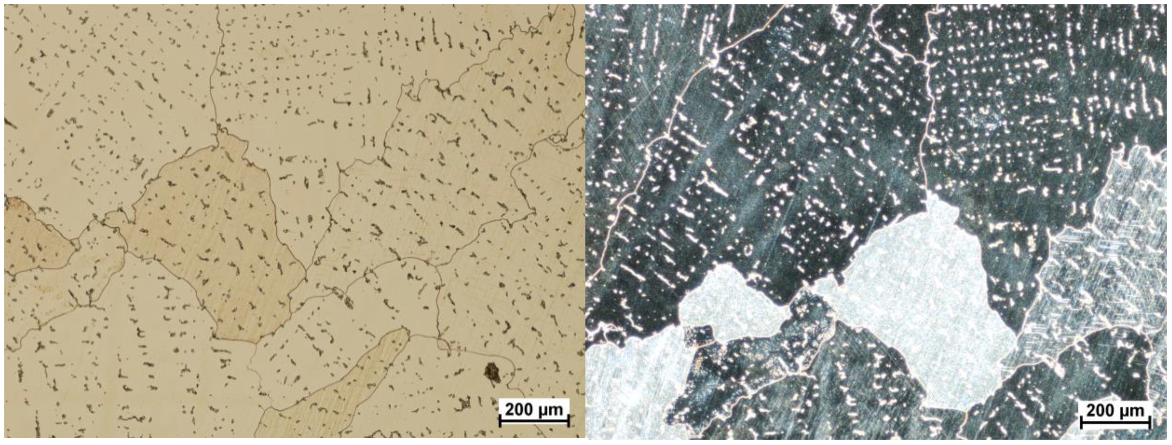
3. Materials and Methods
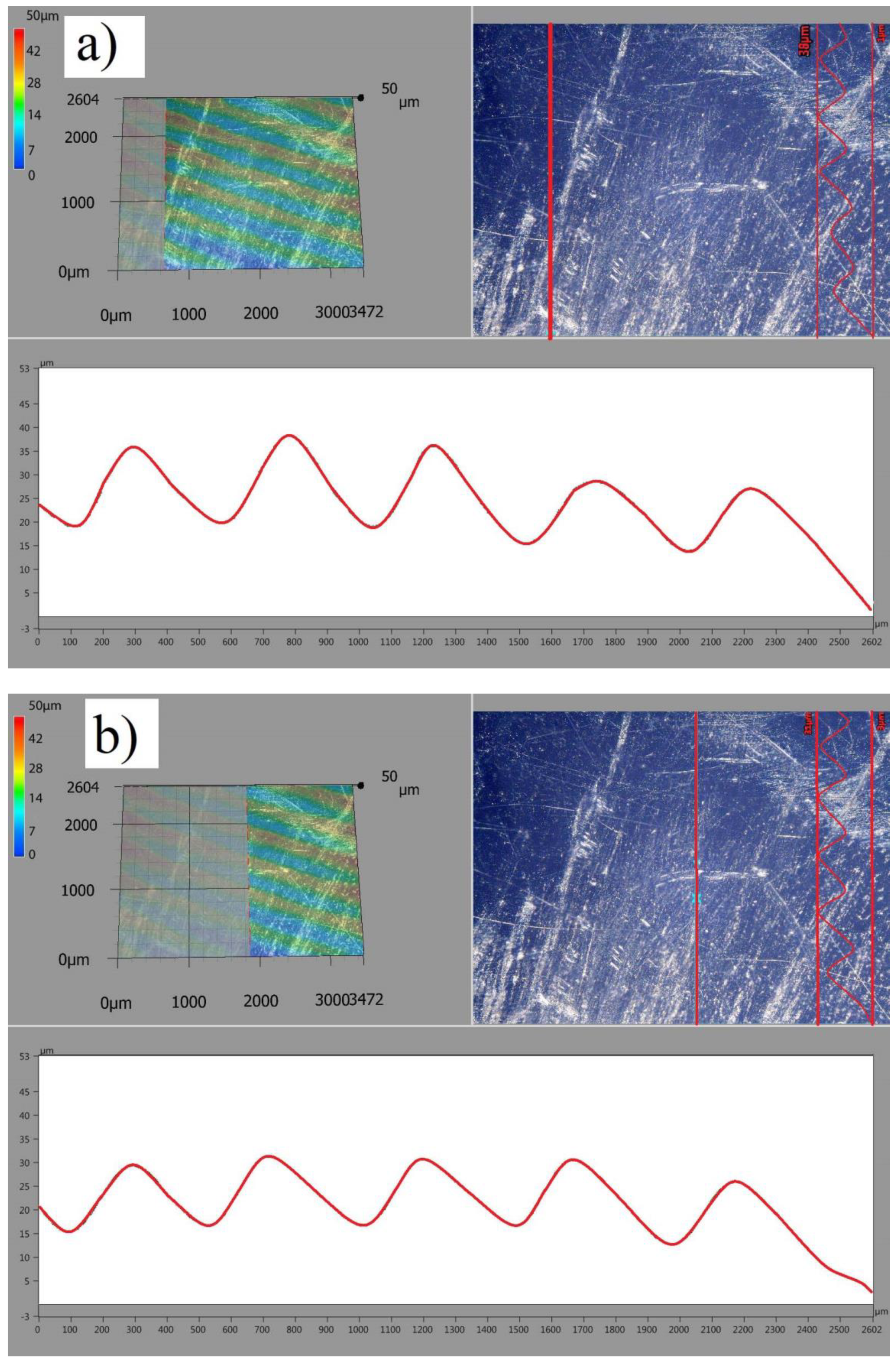
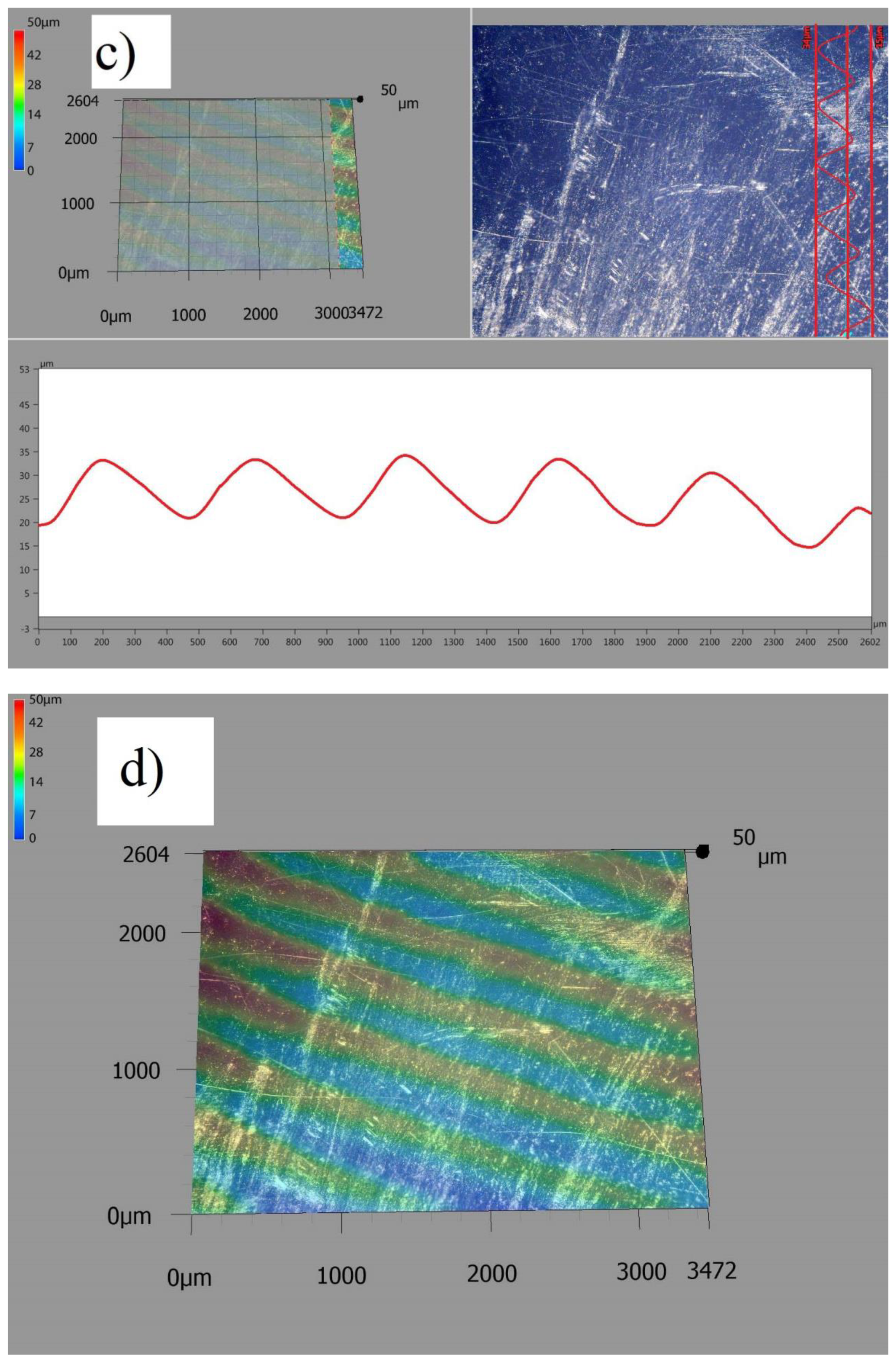
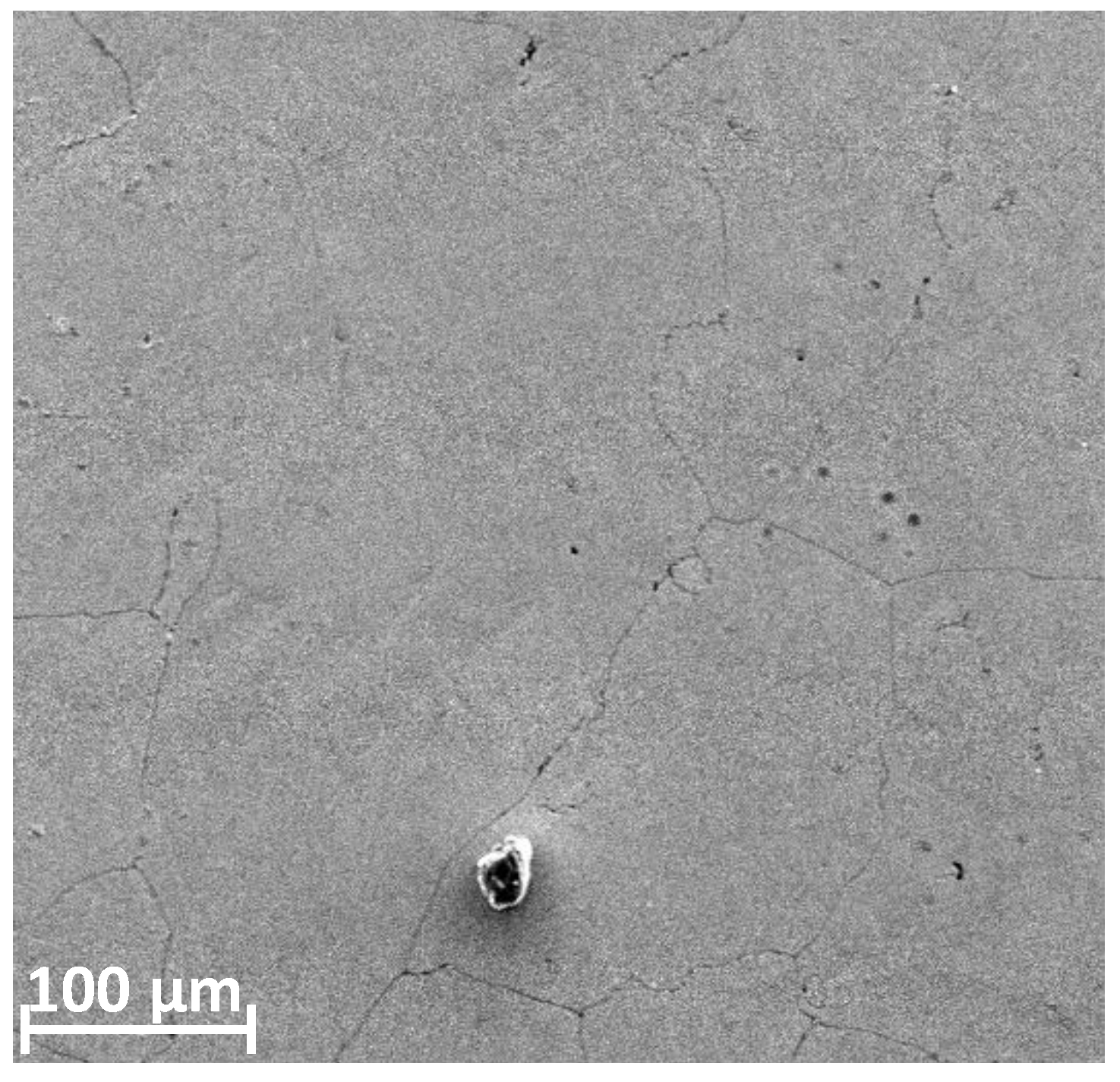
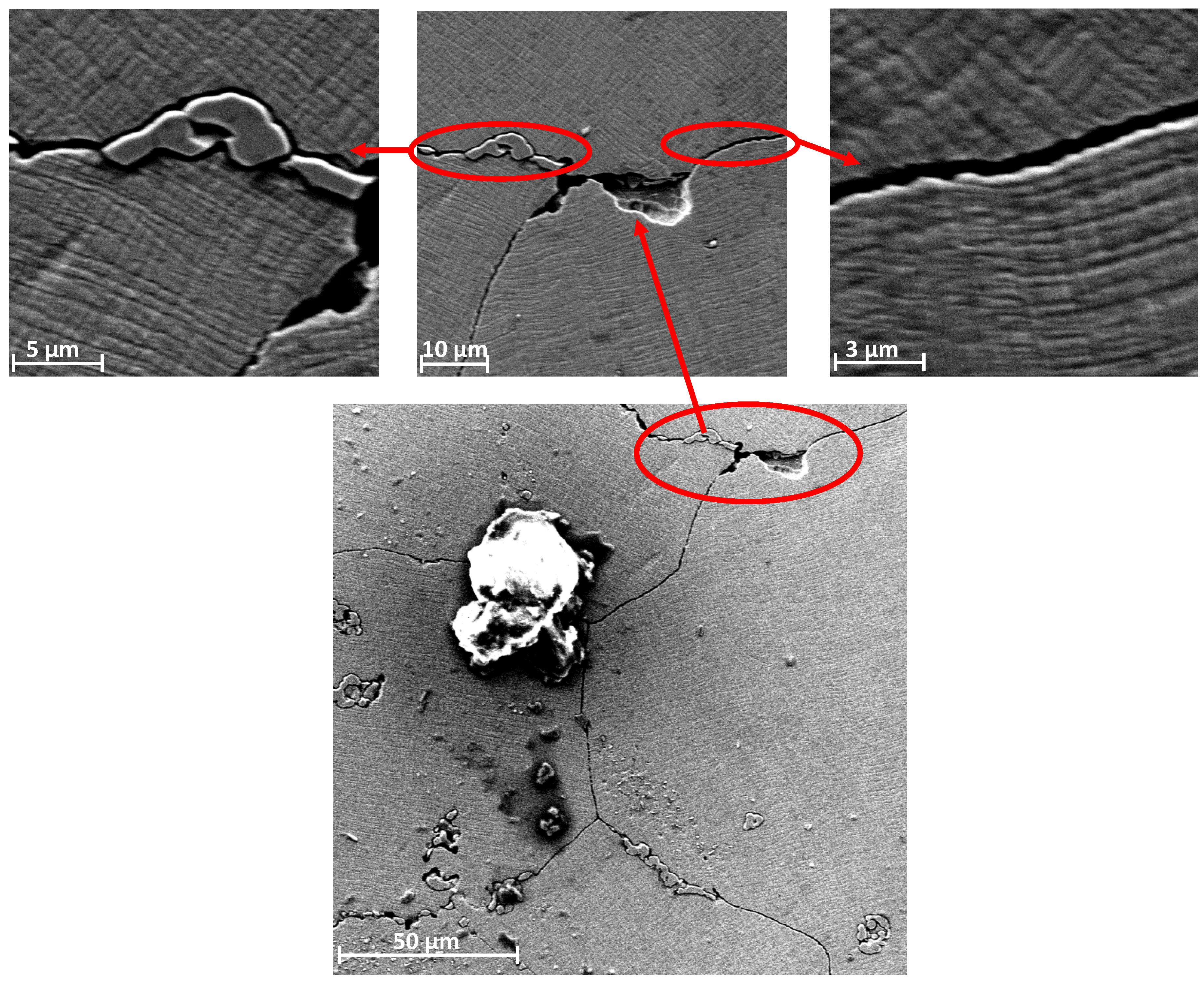
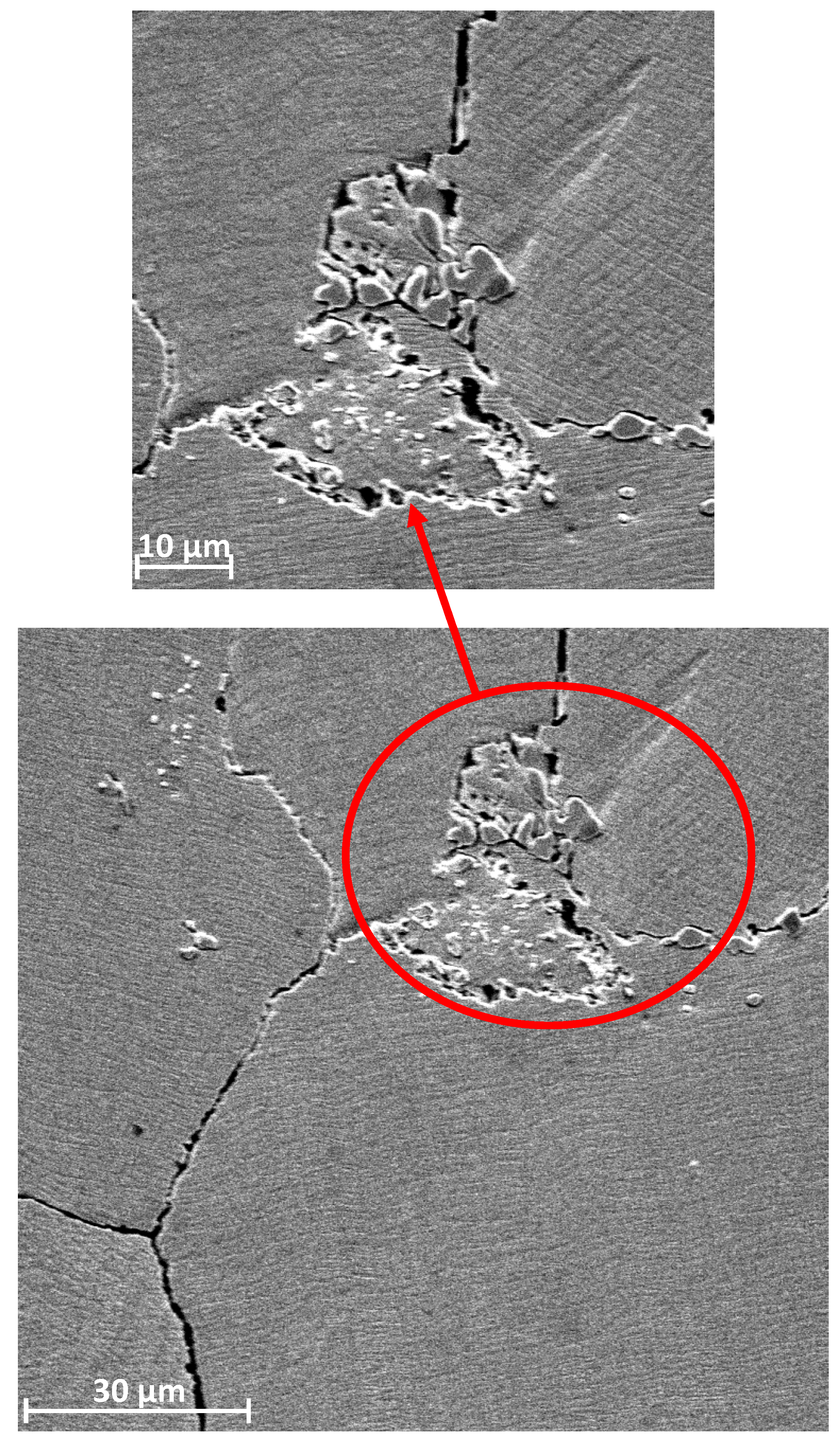
4. Results and Discussion: Assessment of the Destruction of Surfaces of Unicompartmental Endoprostheses
5. Conclusions
Author Contributions
Funding
Acknowledgments
Conflicts of Interest
References
- Haijie, L.; Dasen, L.; Tao, J.; Yi, Y.; Xiaodong, T.; Wei, G. Implant survival and complication profiles of endoprostheses for treating tumor around the knee in adults: A systematic review of the literature over the past 30 years. J. Arth. 2018, 33, 1275–1287. [Google Scholar] [CrossRef] [PubMed]
- Bergschmidt, P.; Ellenrieder, M.; Bader, R.; Kluess, D.; Finze, S.; Schwemmer, B.; Mittelmeier, W. Prospective comparative clinical study of ceramic and metallic femoral components for total knee arthroplasty over a five-year follow-up period. Knee 2016, 23, 871–876. [Google Scholar] [CrossRef] [PubMed]
- Winnock de Grave, P.; Barbier, J.; Luyckx, T.; Ryckaert, A.; Gunst, P.; Van den Daelen, L. Outcomes of a fixed-bearing, medial, cemented unicondylar knee arthroplasty design: Survival analysis and functional score of 460 cases. J. Arthroplast. 2018, 33, 2792–2799. [Google Scholar] [CrossRef] [PubMed] [Green Version]
- Chan, C.W.; Smith, G.C.; Lee, S. A preliminary study to enhance the tribological performance of cocrmo alloy by fibre laser remelting for articular joint implant applications. Lubricants 2018, 6, 24. [Google Scholar] [CrossRef] [Green Version]
- Clinical Outcomes and Statistics of Knee Replacement. Available online: https://www.healthline.com/health/total-knee-replacement-surgery/outcomes-statistics-success-rate#takeaway (accessed on 5 April 2020).
- Singh, J.A.; Yu, S.; Chen, L.; Cleveland, J.D. Rates of total joint replacement in the United States: Future projections to 2020–2040 using the National Inpatient Sample. J. Rheumatol. 2019, 46, 1134–1140. [Google Scholar] [CrossRef] [PubMed]
- Cook, M.J.; Sorial, A.K.; Lunt, M.; Board, T.N.; O’Neill, T.W. Effect of timing and duration of statin exposure on risk of hip or knee revision arthroplasty: A population-based cohort study. J. Rheumatol. 2020, 47, 441–448. [Google Scholar] [CrossRef]
- Endoprotezoplastyka Stawowa w 2012. Narodowy Fundusz Zdrowia. Available online: https://www.google.com/url?sa=t&rct=j&q=&esrc=s&source=web&cd=3&ved=2ahUKEwj6of6EmanpAhW3URUIHR1QDhkQFjACegQIAhAB&url=https%3A%2F%2Fwww.nfz.gov.pl%2Fdownload%2Fgfx%2Fnfz%2Fpl%2Fdefaultstronaopisowa%2F349%2F5%2F1%2F2013_05_07_endoprotezy_2012_analiza.pdf&usg=AOvVaw0Kjy-f2PbBqX9BcpYK1Rt7 (accessed on 5 April 2020).
- Realizacja Świadczeń Endoprotezoplastyki Stawowej w 2013. Narodowy Fundusz Zdrowia. Available online: https://www.google.com/url?sa=t&rct=j&q=&esrc=s&source=web&cd=1&cad=rja&uact=8&ved=2ahUKEwjSvq_ZmKnpAhWUunEKHcUNCNMQFjAAegQIBRAB&url=https%3A%2F%2Fwww.nfz.gov.pl%2Fdownload%2Fgfx%2Fnfz%2Fpl%2Fdefaultstronaopisowa%2F349%2F1%2F1%2F2014_06_02_endoprotezoplastyka_2013.pdf&usg=AOvVaw3U-6u-s3j5uaEjZ4BoLg3C (accessed on 5 April 2020).
- Realizacja Świadczeń Endoprotezoplastyki Stawowej w 2014. Narodowy Fundusz Zdrowia. Available online: https://www.google.com/url?sa=t&rct=j&q=&esrc=s&source=web&cd=1&cad=rja&uact=8&ved=2ahUKEwjDxI7CmKnpAhXUtXEKHV6BDt0QFjAAegQIBBAB&url=https%3A%2F%2Fwww.nfz.gov.pl%2Fdownload%2Fgfx%2Fnfz%2Fpl%2Fdefaultstronaopisowa%2F349%2F26%2F1%2Frealizacja_swiadczen_endoprotezoplastyki_stawowej_w_2014_r..pdf&usg=AOvVaw3TgHeBAknPBd8-BofF_iS1 (accessed on 5 April 2020).
- Realizacja Świadczeń Endoprotezoplastyki Stawowej w 2015. Narodowy Fundusz Zdrowia. Available online: https://www.google.com/url?sa=t&rct=j&q=&esrc=s&source=web&cd=1&cad=rja&uact=8&ved=2ahUKEwj_wYOomKnpAhVXTBUIHWMtBb0QFjAAegQIAhAB&url=https%3A%2F%2Fwww.nfz.gov.pl%2Fdownload%2Fgfx%2Fnfz%2Fpl%2Fdefaultstronaopisowa%2F349%2F30%2F1%2Fcbe_za_2015.pdf&usg=AOvVaw2t2rVJdLWx3J0AoiGffuZp (accessed on 5 April 2020).
- Realizacja Świadczeń Endoprotezoplastyki Stawowej w 2016. Narodowy Fundusz Zdrowia. Available online: https://www.google.com/url?sa=t&rct=j&q=&esrc=s&source=web&cd=1&ved=2ahUKEwiIse_zl6npAhWStHEKHbbUBBsQFjAAegQIBhAB&url=https%3A%2F%2Fwww.nfz.gov.pl%2Fdownload%2Fgfx%2Fnfz%2Fpl%2Fdefaultstronaopisowa%2F349%2F34%2F1%2Fcbe_za_2016.pdf&usg=AOvVaw3rMSswyJvi9Kk4lTJ9eTib (accessed on 5 April 2020).
- Realizacja Świadczeń Endoprotezoplastyki Stawowej w 2017. Narodowy Fundusz Zdrowia. Available online: https://www.google.com/url?sa=t&rct=j&q=&esrc=s&source=web&cd=1&ved=2ahUKEwjn5-nYl6npAhVYUhUIHQWDBEYQFjAAegQIBhAB&url=https%3A%2F%2Fwww.nfz.gov.pl%2Fdownload%2Fgfx%2Fnfz%2Fpl%2Fdefaultstronaopisowa%2F349%2F38%2F1%2Frealizacja_swiadczen_endoprotezoplastyki_stawowej_w_2017_r.pdf&usg=AOvVaw03lXZ58OJNIXfI1M9EAabT (accessed on 5 April 2020).
- Realizacja Świadczeń Endoprotezoplastyki Stawowej w 2018. Narodowy Fundusz Zdrowia. Available online: https://www.google.com/url?sa=t&rct=j&q=&esrc=s&source=web&cd=2&ved=2ahUKEwio75mAl6npAhUEXRUIHXzbAh4QFjABegQIAhAB&url=https%3A%2F%2Fwww.nfz.gov.pl%2Fdownload%2Fgfx%2Fnfz%2Fpl%2Fdefaultstronaopisowa%2F349%2F38%2F1%2Frealizacja_swiadczen_endoprotezoplastyki_stawowej_w_2017_r.pdf&usg=AOvVaw03lXZ58OJNIXfI1M9EAabT (accessed on 5 April 2020).
- Benazzo, F. Całkowita endoprotezoplastyka stawu kolanowego wchodzi w nową fazę. CeraNews 2015, 1, 3–4. [Google Scholar]
- Mittelmeierem, W. Przyszłość endoprotezoplastyki stawu kolanowego: Komponenty ceramiczne wchodzą do gry. CeraNews 2015, 1, 5–7. [Google Scholar]
- Bergschmidt, P.; Bader, R.; Ganzer, D.; Hauzeur, C.H.; Lohmann, C.H.; Krüger, A.; Rüther, W.; Tigani, D.; Rani, N.; Esteve, J.L.; et al. Prospective multi-centre study on a composite ceramic femoral component in total knee arthroplasty: Five-year clinical and radiological outcomes. Knee 2015, 22, 185–195. [Google Scholar] [CrossRef]
- Walker, T.; Zahn, N.; Bruckner, T.; Streit, M.R.; Mohr, G.; Aldinger, P.R.; Clarius, M.; Gotterbarm, T. Mid-term Results of Lateral Unicondylar Mobile Bearing Knee Arthroplasty: A Multicentre Study of 363 Cases. Bone Joint J. 2018, 100, 42–49. [Google Scholar] [CrossRef]
- Affatato, S.; Valigi, M.C.; Logozzo, S. Knee Wear Assessment: 3D Scanners Used as a Consolidated Procedure. Materials 2020, 13, 2349. [Google Scholar] [CrossRef] [PubMed]
- Błażewicz Stanisław, Marciniak Jan: Inżynieria Biomedyczna Podstawy i Zastosowanie. Tom 4. Biomateriały; EXIT: Warsaw, Poland, 2017.
- Romuald Będziński: Mechanika Techniczna. Biomechanika; Instytut Podstawowych Problemów Techniki Polskiej Akademii Nauk: Warsaw, Poland, 2011.
- Błaszczyk, J.W. Biomechanika Kliniczna; PZWL Wydawnictwo Lekarskie: Warsaw, Poland, 2019. [Google Scholar]
- Bao, Y.; Kudo, T.; Cao, S.; Munoz, A.I.; Mischler, S. Passivation Charge Density of CoCrMo Alloy in Different Aqueous Solutions. J. Bio Tribo-Corros. 2020, 6, 58. [Google Scholar] [CrossRef]
- Mell, S.P.; Fullam, S.; Wimmer, M.A.; Lundberg, H.J. Computational Parametric Studies for Preclinical Evaluation of Total Knee Replacements. CMBBE 2019, 36, 60–85. [Google Scholar] [CrossRef]
- Pronk, Y.; Paters, A.A.M.; Brinkman, J.M. No difference in patient satisfaction after mobile bearing or fixed bearing medial unicompartmental knee arthroplasty. Knee Surg. Sports Traumatol. Arthrosc. 2020. [Google Scholar] [CrossRef]
- Szarek, A. Biomechaniczne i Biomateriałowe Determinanty Aseptycznego Obluzowania Endoprotez Stawu Biodrowego Człowieka; Publishing House of the Czestochowa University of Technology: Częstochowa, Poland, 2015. [Google Scholar]
- Świerczyńska-Machura, D.; Kieć-Świerczyńska, M.; Kręcisz, B.; Pałczyński, C. Alergia na składowe implantów. Alerg. Astma Immunol. 2004, 9, 128–132. [Google Scholar]
- Szarek, A. Mechanical Destruction of Joints Implants. Izdatel’stvo Nauka i Obrazovanie; Publishing House Education and Science s.r.o.: Praga—Dniepr, Czech Republic-Ukraine, 2018. [Google Scholar]
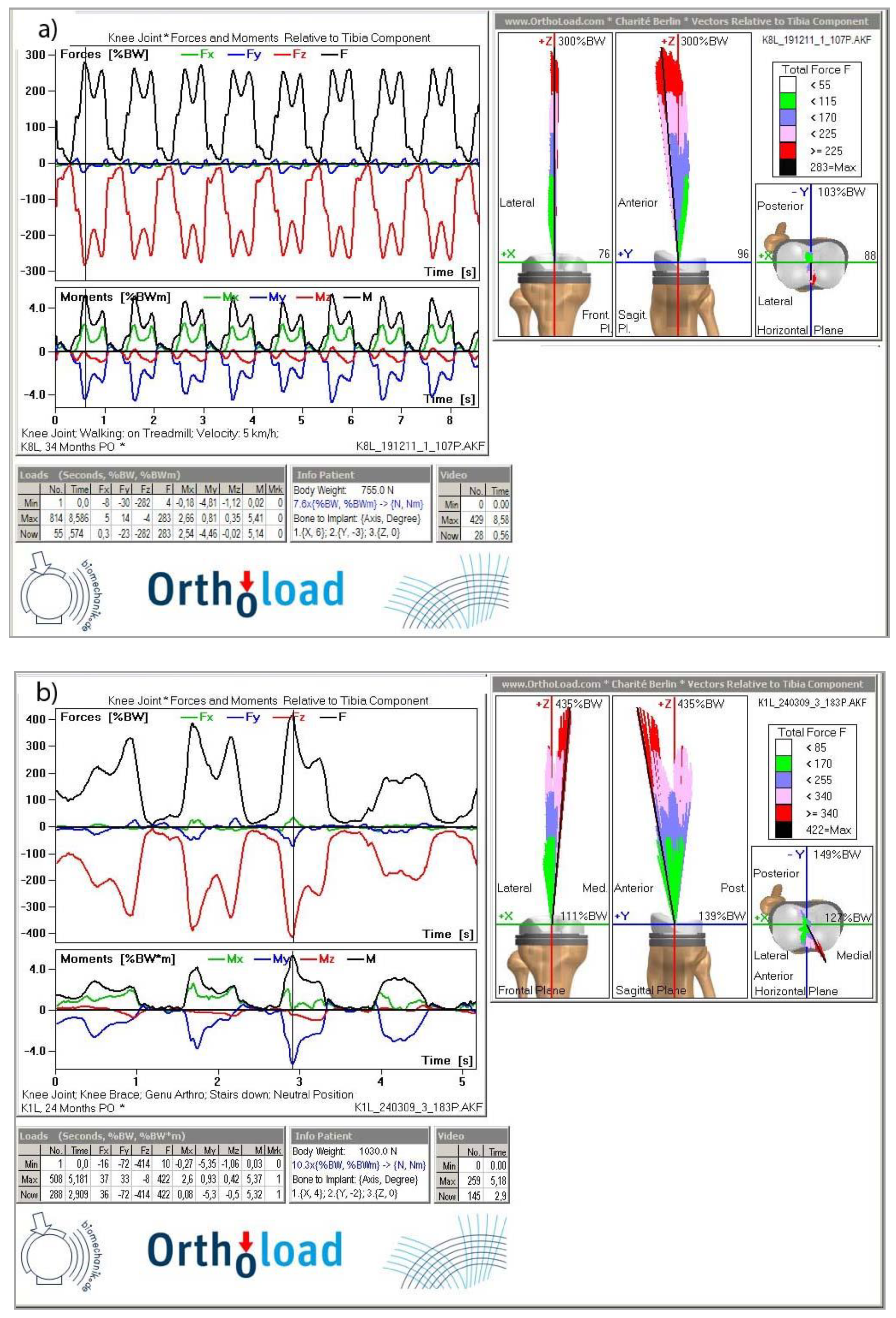
- www.OrthoLoad.com. Available online: https://orthoload.com/database/?implantId=1322&activityId=1536&activityIndentationLevel=3¶meterId=1¶meterIndentationLevel=-1&patientId=all&fileId=k8l_191211_1_107p&fileType=t&selectBox=file, (accessed on 5 April 2020).
- www.OrthoLoad.com. Available online: https://orthoload.com/database/?implantId=1322&activityId=2295&activityIndentationLevel=2¶meterId=880¶meterIndentationLevel=0&patientId=all&fileId=k1l_240309_3_183p&fileType=t&selectBox=file (accessed on 5 April 2020).
- Kusz, D.; Wojciechowski, P.; Cielinski, L.S.; Iwaniak, A.; Jurkojc, J.; Gasiorek, D. Stress distribution around TKR implant: Are lab results consistent with observational studies. Acta Bioeng. Biomech. 2008, 10, 21–26. [Google Scholar] [PubMed]
- Nardini, F.; Belvedere, C.; Sancisi, N.; Conconi, M.; Leardini, A.; Durante, S.; Parenti-Castelli, V. An Anatomical-Based Subject-Specific Model of In-Vivo Knee Joint 3D Kinematics From Medical Imaging. Appl. Sci. 2020, 10, 2100. [Google Scholar] [CrossRef] [Green Version]
- Stetter, B.J.; Ringhof, S.; Krafft, F.C.; Sell, S.; Stein, T. Estimation of Knee Joint Forces in Sport Movements Using Wearable Sensors and Machine Learning. Sensors 2019, 19, 3690. [Google Scholar] [CrossRef] [Green Version]
- Jiang, H.; Xiang, S.; Guo, Y.; Wang, Z. A wireless visualized sensing system with prosthesis pose reconstruction for total knee arthroplasty. Sensors 2019, 19, 2909. [Google Scholar] [CrossRef] [Green Version]
- Szarek, A.; Wolański, W.; Szyproski, J.; Kopuliński, Ł.; Radecki, M.; Bednarek, B. Using Engineering Tools for Choosing Hip Joint Endoprosthesis. Sovrem. Naucn. Vestn. 2013, 32, 82–92. [Google Scholar]
- Vitale, M.M.J.A.; Stucovitz, E.; Romagnoli, S. Simultaneous bilateral unicompartmental knee replacement improves gait parameters in patients with bilateral knee osteoarthritis. Knee 2019, 26, 1413–1420. [Google Scholar] [CrossRef]
- Kakara, R.S.; Fub, Y.C.; Kinseyc, T.L.; Brownd, C.N.; Mahoneyce, O.M.; Simpsone, K.J. Lower limb kinematics of unicompartmental knee arthroplasty individuals during stair ascent. J. Orthop. 2020, 22, 173–178. [Google Scholar] [CrossRef] [PubMed]
- Li, Y.; Kakar, R.S.; Fu, Y.C.; Mahoney, O.M.; Kinsey, T.L.; Simpson, K.J. Knee strength, power and stair performance of the elderly 5 years after unicompartmental knee arthroplasty. Eur. J. Orthop. Surg. Traumatol. 2018, 28, 1411–1416. [Google Scholar] [CrossRef]
- NBP Exchange Rates. Available online: https://www.money.pl/pieniadze/nbp/srednie/?date=2005-12-30 (accessed on 5 April 2020).
- NBP Exchange Rates. Available online: https://www.money.pl/pieniadze/nbp/srednie/?date=2018-12-31 (accessed on 5 April 2020).
- Maśliński, S.L.; Ryżewski, J. Patofizjologia, 4th ed.; PZWL Wydawnictwo Lekarskie: Warsaw, Poland, 2019. [Google Scholar]
- Szarek, A. Assessment of wear of metal heads in heap joint prosthesis removed from human body due to aseptic loosening. Eng. Biomater. 2008, 11, 6–10. [Google Scholar]
- Aoki, H.; Kato, K. Studies on the application of apatite to dental materials. J. Dent. Eng. 1977, 18, 86–89. [Google Scholar]
- Anderson, F.C.; Pandy, M.G. Dynamic simulation of human motion in three dimensions. In Proceedings of the Sixth Internetional Symposium on the 3D Analysis of Human Movement, Cape Town, South Africa, 1–4 May 2000; pp. 1–4. [Google Scholar]
- Aoki, H. Medicalapplication of Hydroźyapatite; Ishiyaku euroamerica: Tokio, Japan, 1994. [Google Scholar]
- Akahori, T.; Niinomi, M. Fracture characteristic of fatigued Ti-6Al.-4V ELI as an implant material. Mater. Sci. Eng. 1998, 243, 237–243. [Google Scholar] [CrossRef]
- Jiang, X.J.; Whitehouse, D.V. Technological shifts in surface metrology. CIRP Manuf. Technol. 2012, 61, 815–836. [Google Scholar] [CrossRef]
- Leach, R. Characterization of Areal Surface Texture; Springer: Berlin, Germany, 2013. [Google Scholar]


| Co [%] | Cr [%] | Mo [%] | Si [%] | C [%] |
|---|---|---|---|---|
| 63.17 | 27.67 | 4.94 | 0.79 | 3.42 |
| Sample Tested | HV100 | Re [MPa] | KIC [MPa•m1/2] |
|---|---|---|---|
| Tibial Component, New | |||
| Sample 1 Sample 2 | 365 360 359 360 362 358 Mean 360 Standard Deviation 2.50 | 122 120 119 120 120 119 Mean 120 Standard Deviation 1.09 | 108 104 106 105 108 105 Mean 106 Standard Deviation 1.67 |
| Tibial Component Used for 6 Years | |||
| Sample 1 Sample 2 Sample 3 | 376 378 380 384 380 378 377 388 382 Mean 380 Standard Deviation 3.81 | 125 126 127 128 127 126 126 129 127 Mean 127 Standard Deviation 1.20 | 97 101 102 100 101 102 99 97 101 Mean 100 Standard Deviation 1.94 |
| Tibial Component Used for 12 Years | |||
| Sample 1 | 432 428 431 Mean 430 Standard Deviation 2.52 | 144 142 14 Mean 143 Standard Deviation 1 | 77 77 77 Mean 77 Standard Deviation 0 |
| Unused Tibial Component | |||
| Sample 1 Sample 2 | 397 400 394 407 406 396 Mean 400 Standard Deviation 5.40 | 132 133 131 136 136 131 Mean 133 Standard Deviation 2.25 | 130 129 122 125 127 123 Mean 126 Standard Deviation 3.22 |
| Femoral Component Used for 6 Years | |||
| Sample 1 Sample 2 Sample 3 | 411 406 405 411 416 415 407 411 411 Mean 410 Standard Deviation 3.77 | 137 135 135 137 139 138 135 137 137 Mean 137 Standard Deviation 1.41 | 120 128 131 124 122 121 123 118 121 Mean 123 Standard Deviation 4.07 |
| Femoral Component Used for 12 Years | |||
| Sample 1 | 437 444 438 Mean 440 Standard Deviation 3.78 | 145 148 146 Mean 147 Standard Deviation 1.15 | 100 96 98 Mean 98 Standard Deviation 2 |
© 2020 by the authors. Licensee MDPI, Basel, Switzerland. This article is an open access article distributed under the terms and conditions of the Creative Commons Attribution (CC BY) license (http://creativecommons.org/licenses/by/4.0/).
Share and Cite
Szarek, A.; Stradomski, G.; Łukomska-Szarek, J.; Rydz, D.; Wolański, W.; Joszko, K. Wear Morphology on the Surfaces of CoCrMo Unicompartmental Knee Joint Endoprostheses as Elements of Metal–Metal Friction Nodes. Materials 2020, 13, 2689. https://0-doi-org.brum.beds.ac.uk/10.3390/ma13122689
Szarek A, Stradomski G, Łukomska-Szarek J, Rydz D, Wolański W, Joszko K. Wear Morphology on the Surfaces of CoCrMo Unicompartmental Knee Joint Endoprostheses as Elements of Metal–Metal Friction Nodes. Materials. 2020; 13(12):2689. https://0-doi-org.brum.beds.ac.uk/10.3390/ma13122689
Chicago/Turabian StyleSzarek, Arkadiusz, Grzegorz Stradomski, Justyna Łukomska-Szarek, Dariusz Rydz, Wojciech Wolański, and Kamil Joszko. 2020. "Wear Morphology on the Surfaces of CoCrMo Unicompartmental Knee Joint Endoprostheses as Elements of Metal–Metal Friction Nodes" Materials 13, no. 12: 2689. https://0-doi-org.brum.beds.ac.uk/10.3390/ma13122689