On the Role of Hollow Aluminium Oxide Microballoons during Machining of AZ31 Magnesium Syntactic Foam


 , ,
, ,
Abstract
:1. Introduction
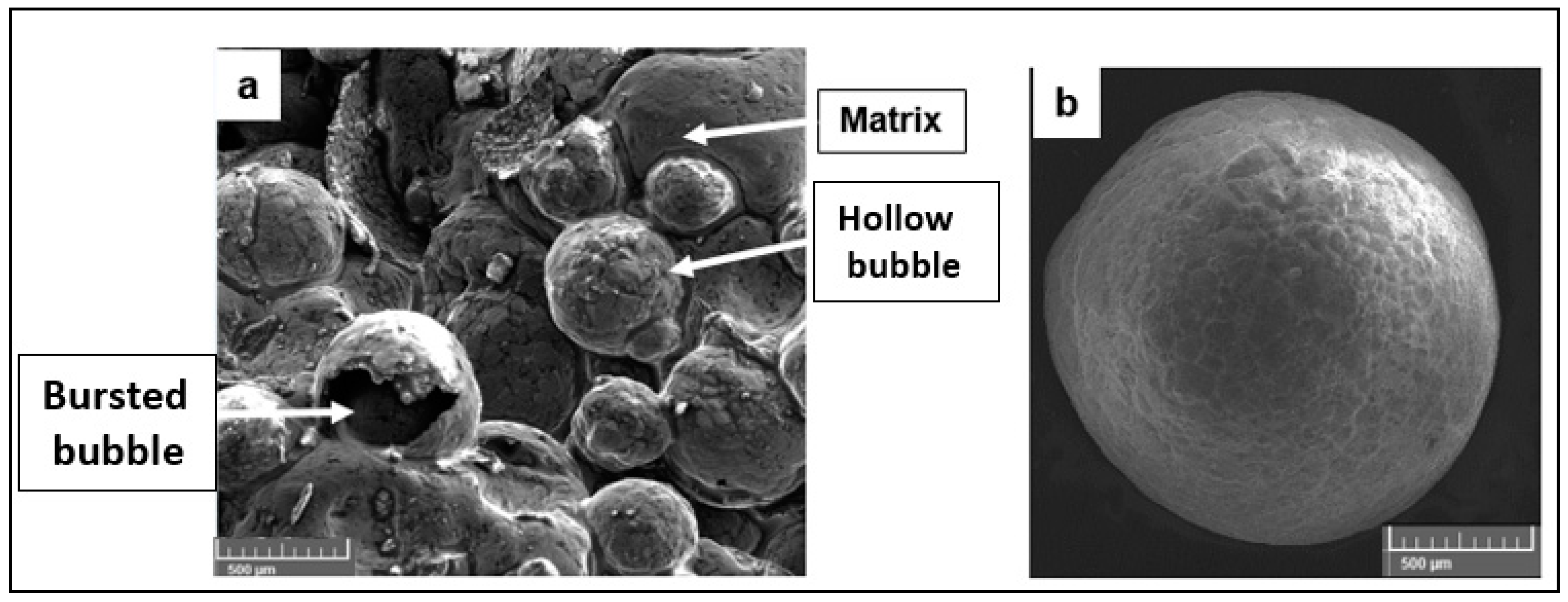
2. Material
Constitutive Model for Closed-Cell Foam
3. Empirical Force Model for Machining Metal Syntactic Foams
3.1. Force due to Plastic Deformation
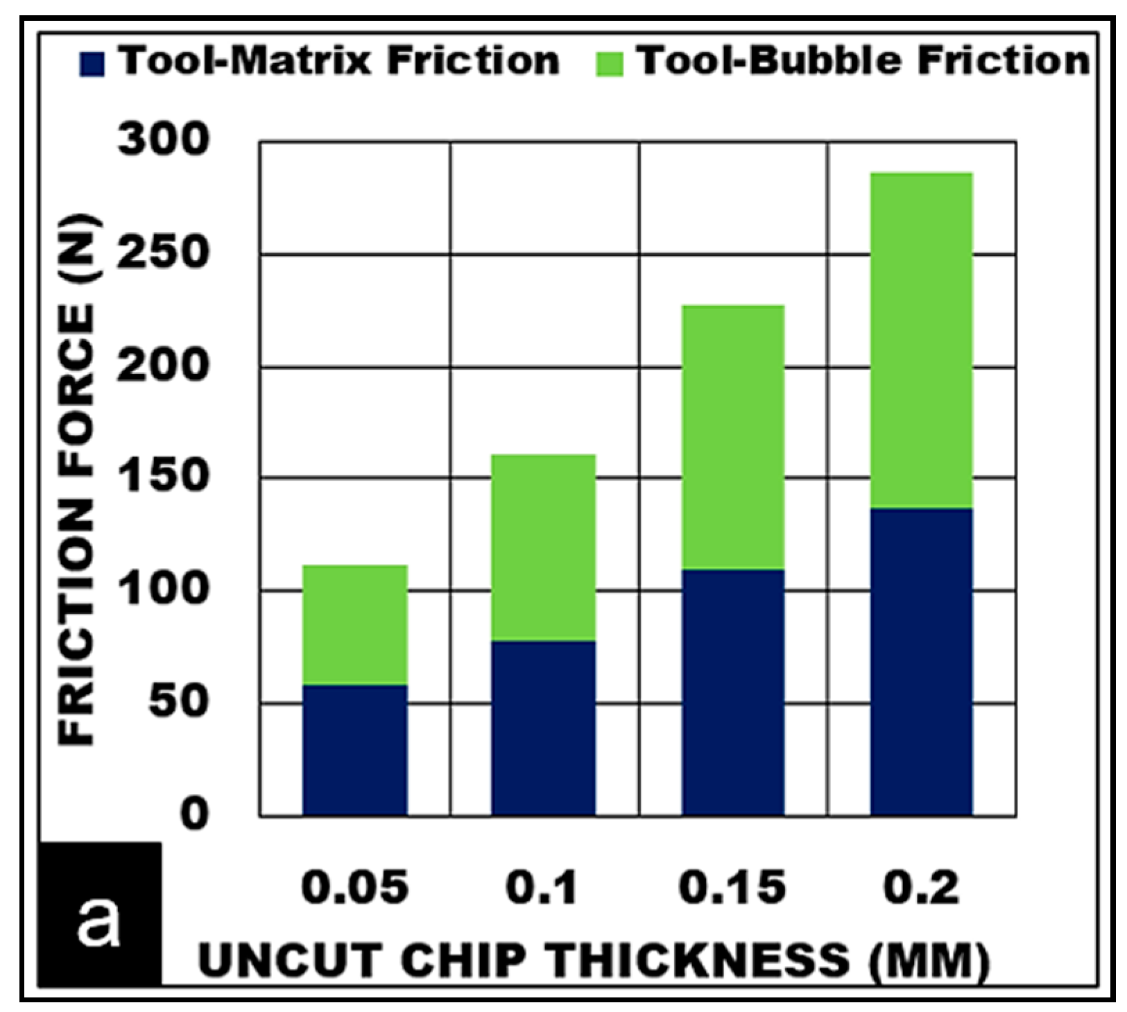
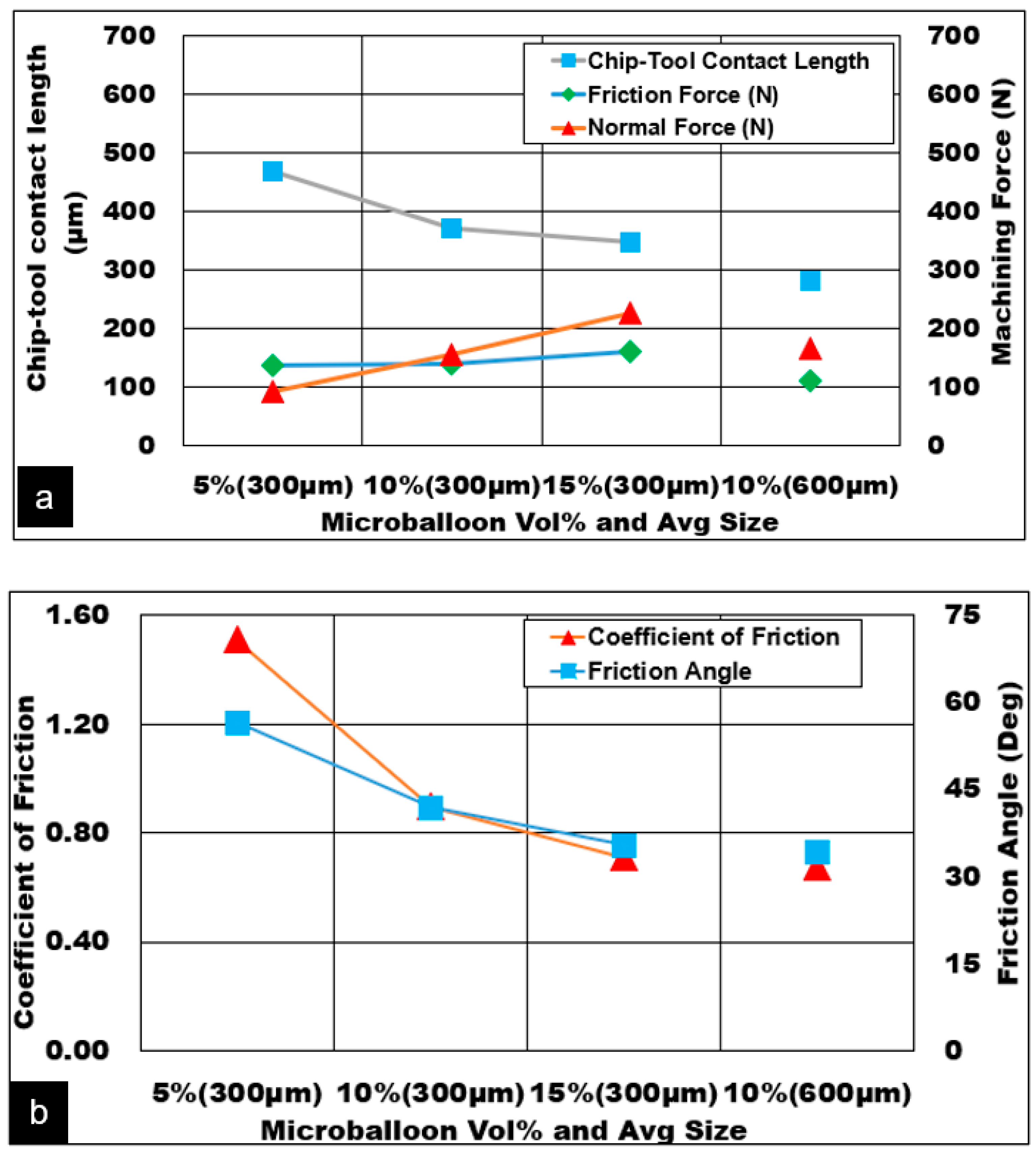
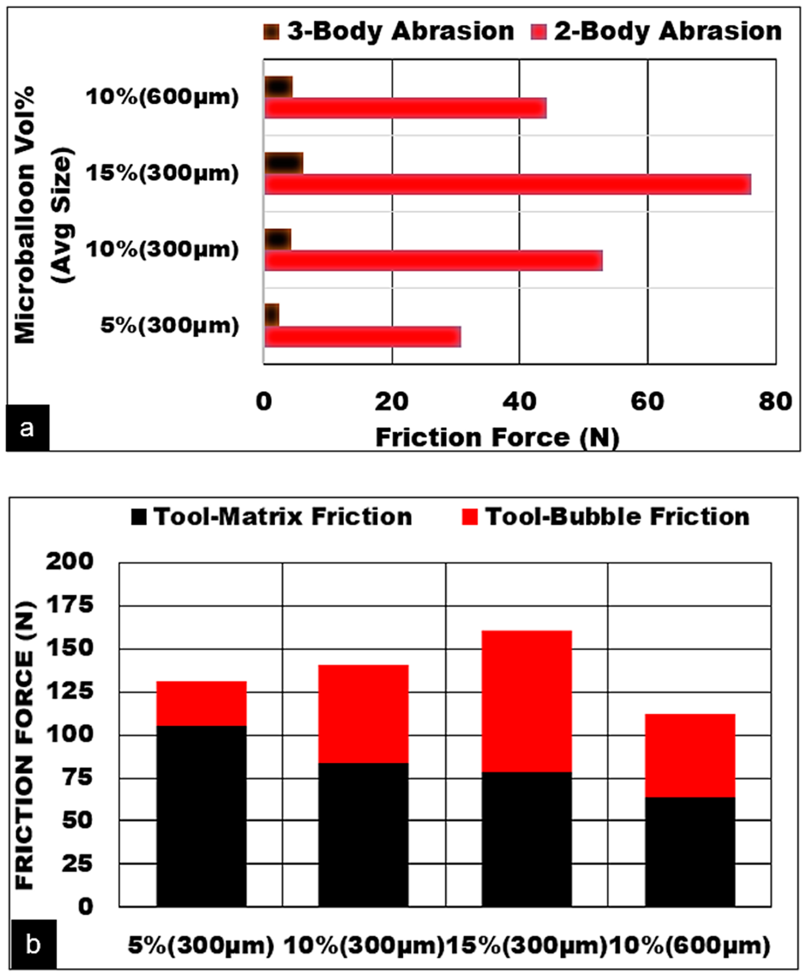
3.2. Determination of Contact Friction between Microballoon/Matrix and Cutting Tool
3.3. Estimation of Cutting Tool Ploughing Force
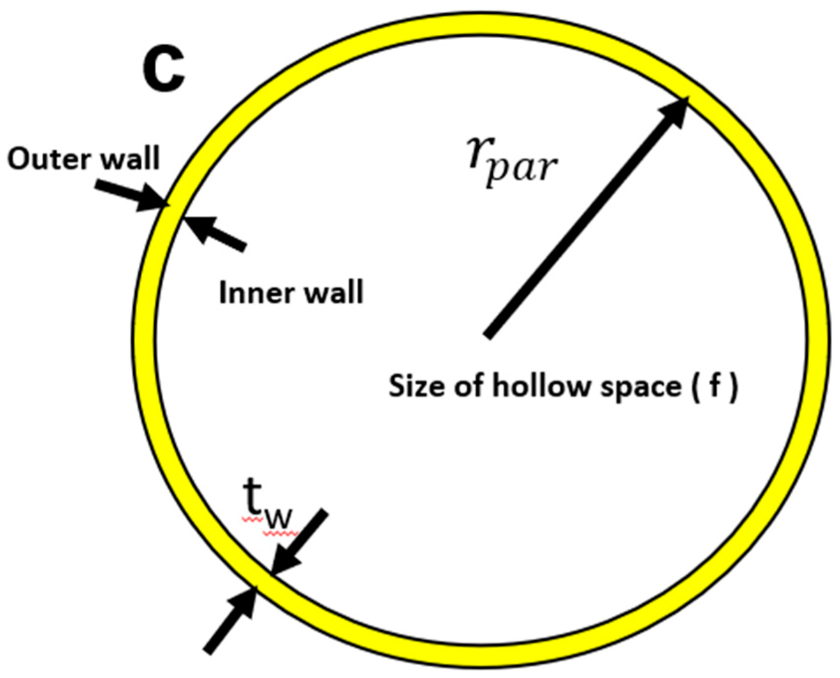
3.4. Hollow Ceramic Microsphere Burst, Crushing and Debonding
4. Experimental Procedure
5. Results and Discussion
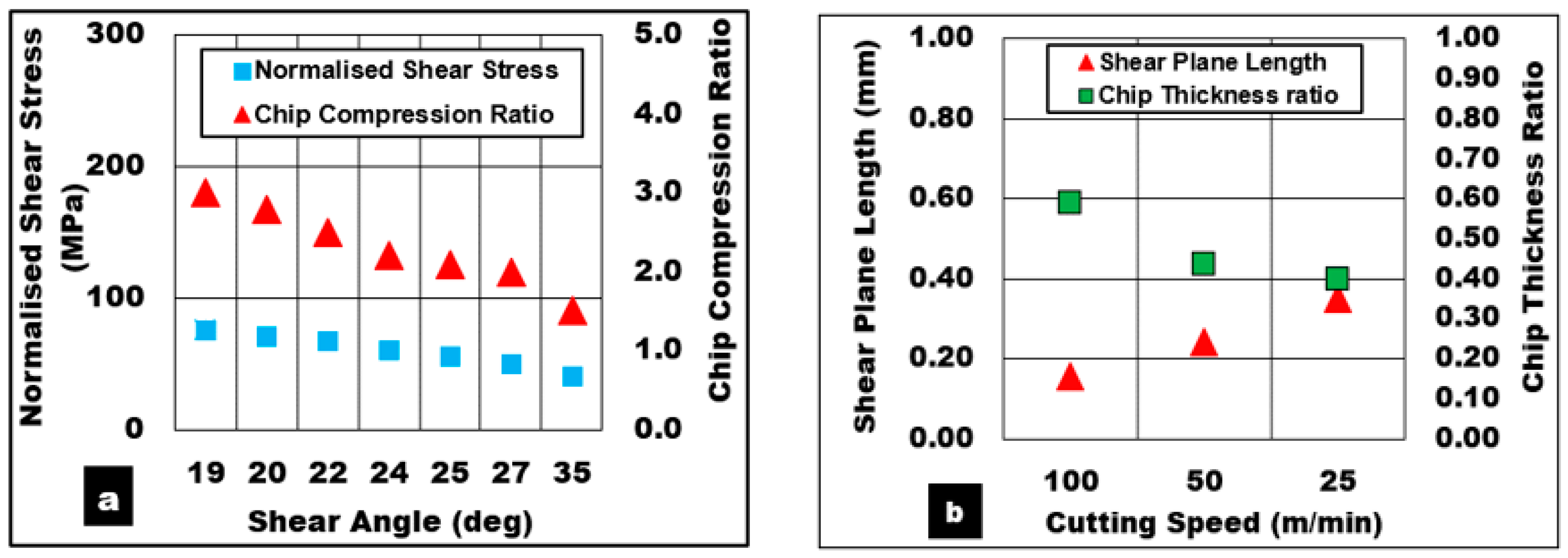
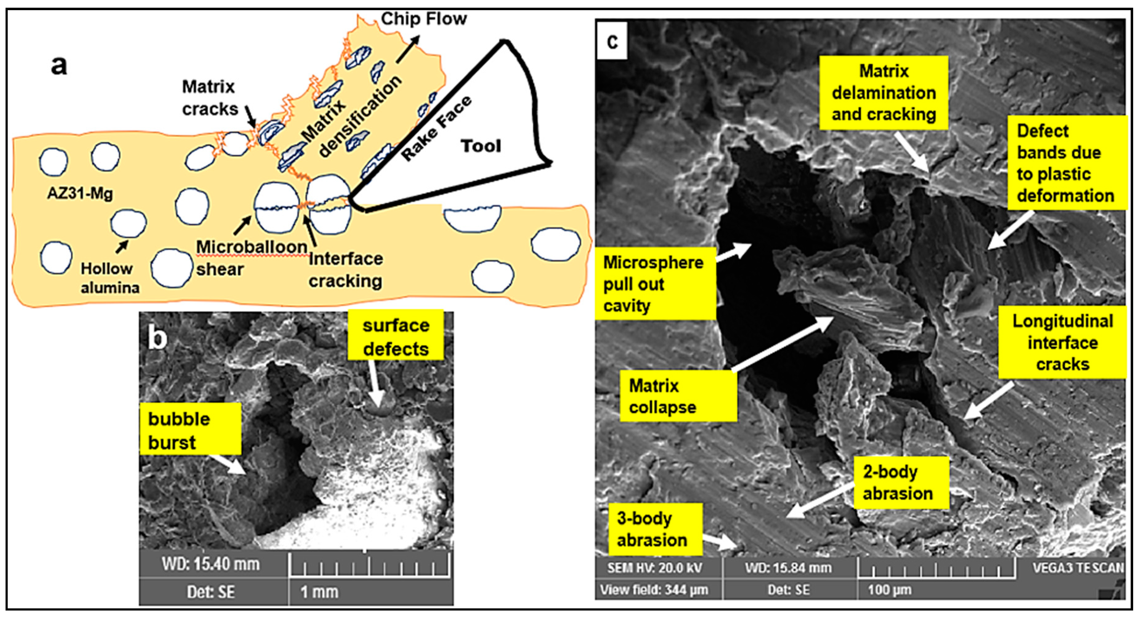
5.1. Deformation Mechanisms in the Primary Shear Zone
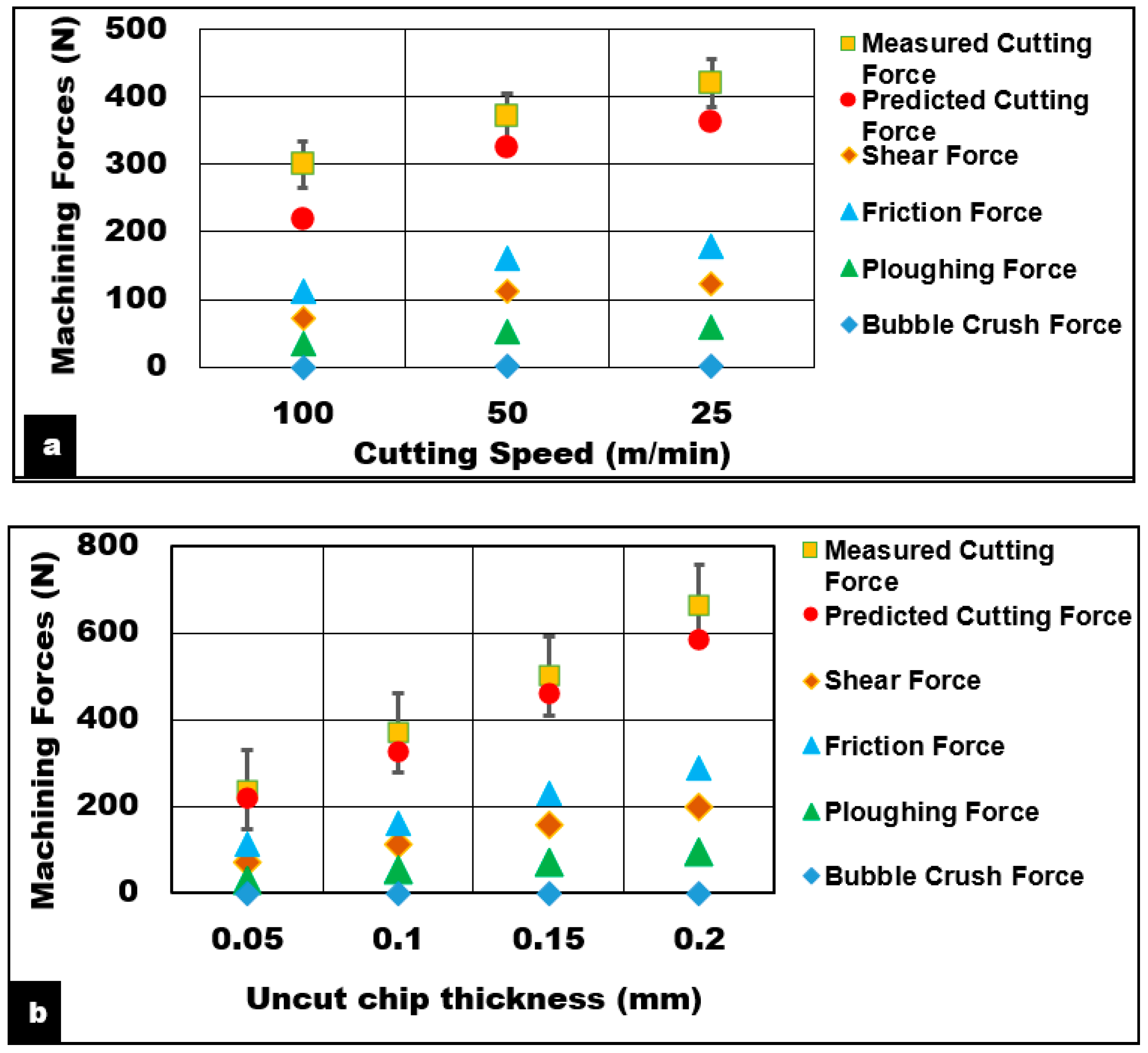
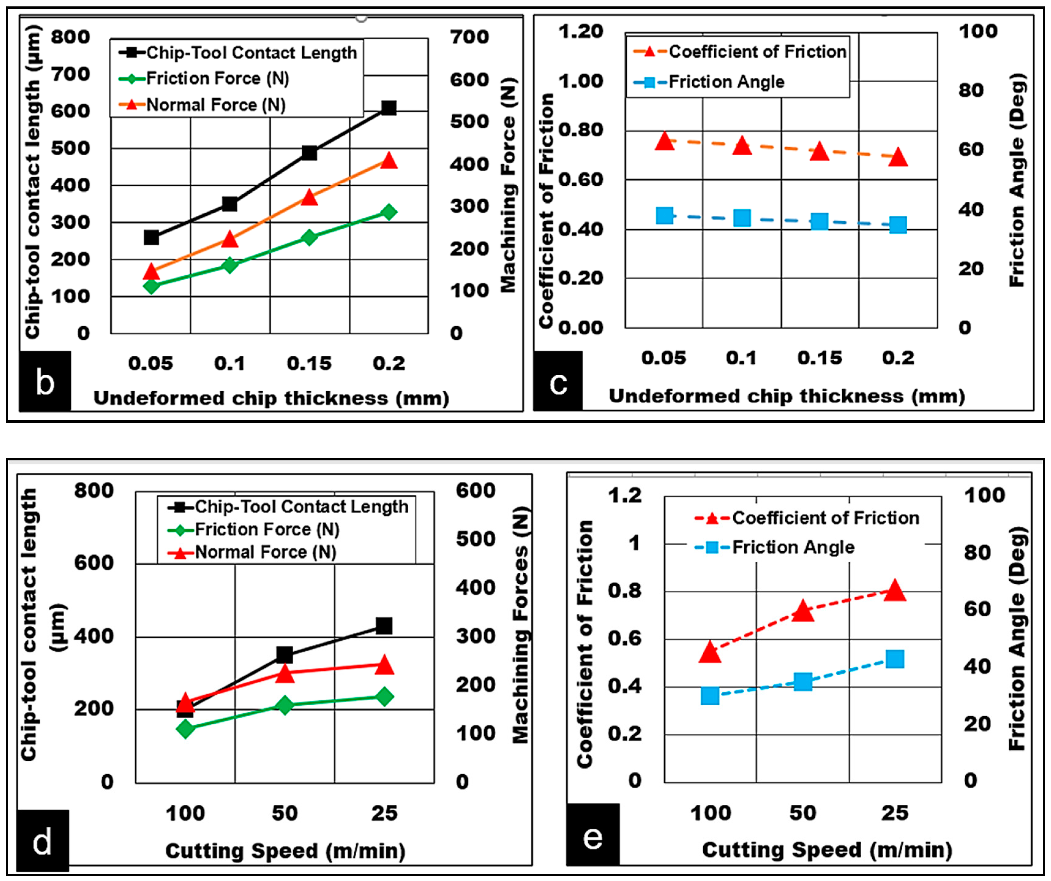
5.1.1. Effect of Cutting Speed
5.1.2. Effect of Uncut Chip Thickness
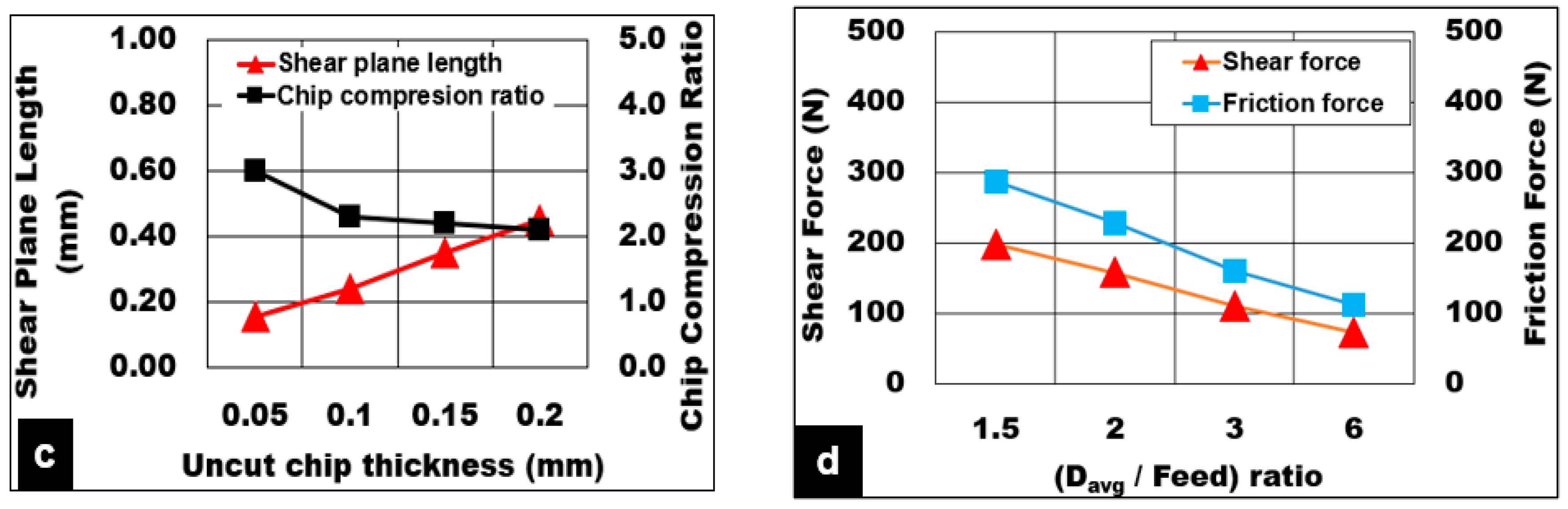
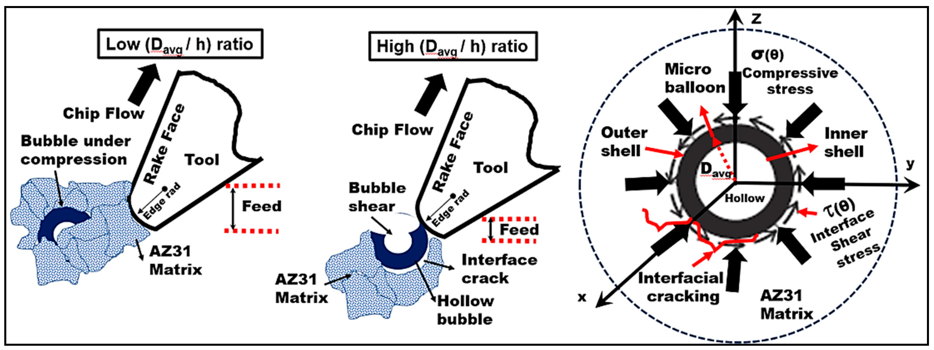
5.2. Effect of (Davg/h) Ratio
5.3. Deformation Mechanisms in the Secondary Shear Zone
5.4. Mechanism of Chip Formation during Cutting Metal Syntactic Foam
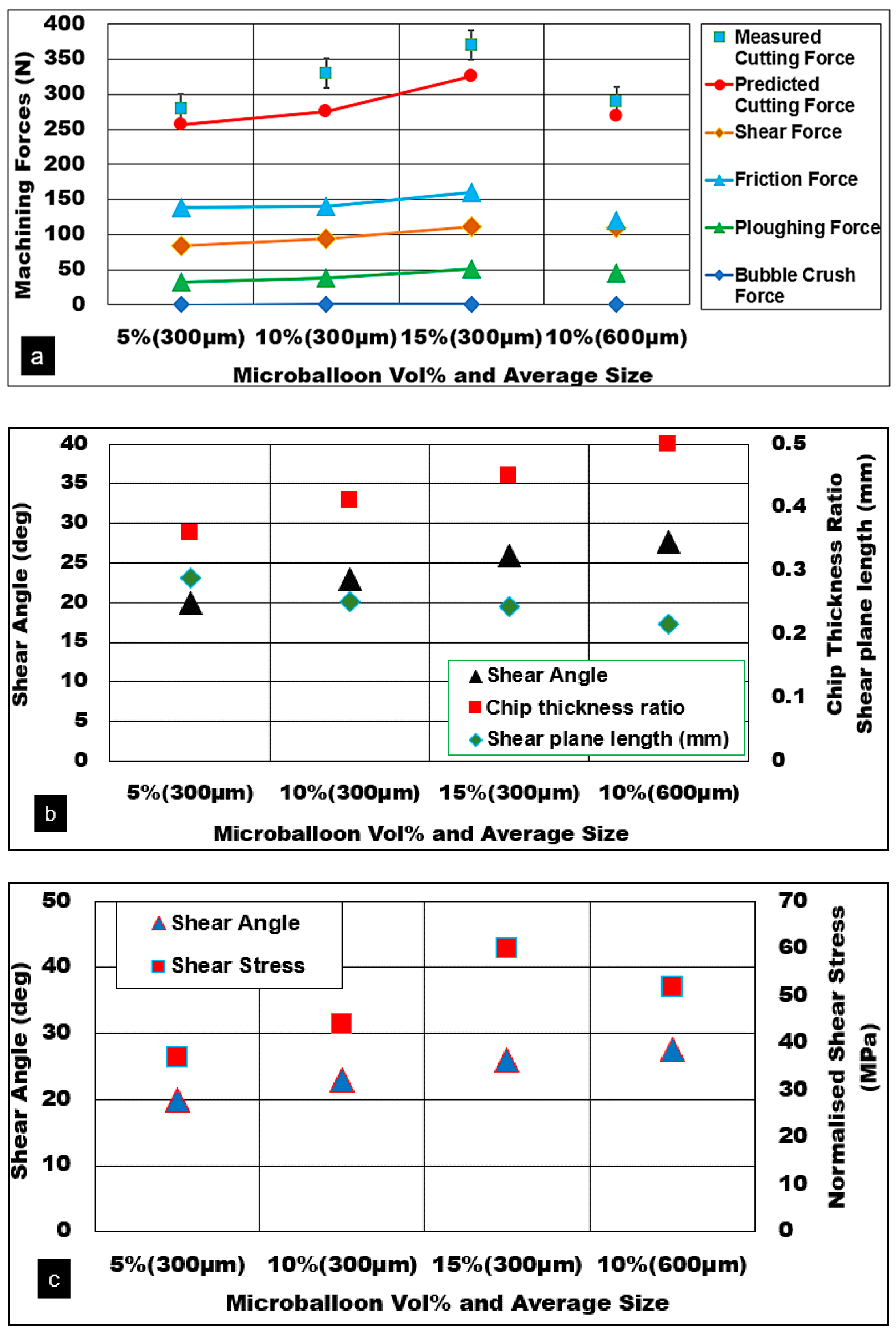
5.5. Effect of Microballoon Volume Fraction and Average Diameter
6. Conclusions
- The higher the microballoon volume fraction and finer their average size, the higher the generated machining forces. Finer balloons improved the shear strength of the matrix, possibly through effective pinning of the grain boundaries.
- A good correlation between changes in key deformation mechanisms of microballoons, such as bubble shear, burst, and fracture with (Davg/h) ratio, is established.
- With an increasing volume fraction of bubbles, the shear angle and normalized shear stress values increased while the co-efficient of friction and friction angle reduced.
- A key deformation mechanism was found to be a combination of bubble burst and fracture through an effective load transfer mechanism with the plastic AZ31 Mg matrix.
- The proposed force model was in better agreement with measured results and was within 10%.
Author Contributions
Funding
Acknowledgments
Conflicts of Interest
Nomenclature
| A,B,C, n, m | Model constants |
| Tm, Tr | Melting and reference temperatures |
| Smax | Peak compressive stress |
| Rma | Area fraction of matrix |
| Rcm | Area fraction of microbubbles/balloons |
| χy | Matrix yield strength |
| Zf | Fracture strength of bubble wall |
| Davg | Average bubble diameter |
| tw | Average wall thickness of the bubble |
| Ew | Bubble crush strength |
| cmf | Bubble volume fraction |
| rpar | Average radius of the bubble |
| St | UTS of the matrix material |
| Tool rake angle | |
| φ | Shear angle |
| p | Equivalent plastic strain |
| b | Width of cut |
| w | Undeformed chip thickness |
| ¶ | Chip compression ratio |
| STo | Tool shear strength |
| SPL | Specific energy for plastic deformation |
| Cthb | Three-body friction |
| Ctb | Two-body friction |
| uthb | Coefficient of friction |
| nthb | Normal force due to three-body rolling |
| Ï | Probability of bubbles engaged in abrasion |
References
- Rohatgi, P.K.; Weiss, D.; Gupta, N. Applications of fly ash in synthesizing low-cost MMCs for automotive and other applications. JOM 2006, 58, 71–76. [Google Scholar] [CrossRef]
- Rohatgi, P.K.; Gupta, N.; Schultz, B.F.; Luong, D.D. The synthesis, compressive properties, and applications of metal matrix syntactic foams. JOM 2011, 63, 36–42. [Google Scholar] [CrossRef]
- Gupta, N.; Rohatgi, P.K. Metal Matrix Syntactic Foams Processing, Microstructure, Properties and Applications; DEStech Publications: Lancaster, PA, USA, 2014. [Google Scholar]
- Weise, J.; Yezerska, O.; Busse, M.; Haesche, M.; Zanetti-Bueckmann, V.; Schmitt, M. Production and properties of micro-porous glass bubble zinc and aluminium composites. Mater Werkst. 2007, 38, 901–906. [Google Scholar] [CrossRef]
- Luong, D.D.; Gupta, N.; Daoud, A.; Rohatgi, P.K. High strain rate compressive characterization of aluminum alloy/Fly ash cenosphere composites. JOM 2011, 63, 53–56. [Google Scholar] [CrossRef]
- Luong, D.D.; Gupta, N.; Rohatgi, P.K. The high strain rate compressive response of Mg-Al alloy/fly Ash cenosphere composites. JOM 2011, 63, 48–52. [Google Scholar] [CrossRef]
- Gupta, N.; Luong, D.D.; Cho, K. Magnesium matrix composite foams—Density, mechanical properties, and applications. Metals (Basel) 2012, 2, 238–252. [Google Scholar] [CrossRef] [Green Version]
- Szlancsik, A.; Katona, B.; Májlinger, K.; Orbulov, I.N. Compressive behavior and microstructural characteristics of iron hollow sphere filled aluminum matrix syntactic foams. Materials (Basel) 2015, 8, 7926–7937. [Google Scholar] [CrossRef] [Green Version]
- Santa Maria, J.A.; Schultz, B.F.; Ferguson, J.B.; Rohatgi, P.K. Al-Al2O3 syntactic foams—Part I: Effect of matrix strength and hollow sphere size on the quasi-static properties of Al-A206/Al2O3 syntactic foams. Mater. Sci. Eng. A 2013, 582, 415–422. [Google Scholar] [CrossRef]
- Balch, D.K.; O’Dwyer, J.G.; Davis, G.R.; Cady, C.M.; Gray, G.T.; Dunand, D.C. Plasticity and damage in aluminum syntactic foams deformed under dynamic and quasi-static conditions. Mater. Sci. Eng. A 2005, 391, 408–417. [Google Scholar] [CrossRef]
- Tao, X.F.; Zhao, Y.Y. Compressive failure of Al alloy matrix syntactic foams manufactured by melt infiltration. Mater. Sci. Eng. A 2012, 549, 228–232. [Google Scholar] [CrossRef]
- Altenaiji, M.; Guan, Z.W.; Cantwell, W.J.; Zhao, Y.; Schleyer, G.K. Characterisation of aluminium matrix syntactic foams under drop weight impact. Mater. Des. 2014, 59, 296–302. [Google Scholar] [CrossRef]
- Bram, M.; Kempmann, C.; Laptev, A.; Stöver, D.; Weinert, K. Investigations on the Machining of sintered titanium foams utilizing face milling and peripheral grinding. Adv. Eng. Mater. 2003, 5, 441–447. [Google Scholar] [CrossRef]
- Qiao, H.; Tejas, G. Murthy and Christopher Saldana, Structure and Deformation of gradient metal foams produced by machining. J. Manuf. Sci. Eng. 2019, 141, 7. [Google Scholar] [CrossRef]
- Fakhri, M.A.; Bordatchev, E.V.; Tutunea-Fatan, O.R. Framework for evaluation of the relative contribution of the process on porosity–cutting force dependence in micromilling of titanium foams. Proc. Inst. Mech. Eng. Part B J. Eng. Manuf. 2013, 227, 1635–1650. [Google Scholar] [CrossRef]
- Heidari, M.; Yan, J. Material removal mechanism and surface integrity in ultraprecision cutting of porous titanium. Precis. Eng. 2018, 52, 356–369. [Google Scholar] [CrossRef]
- Heidari, M.; Yan, J. Fundamental characteristics of material removal and surface.formation in diamond turning of porous carbon. Int. J. Addit. Subtractive Mater. Manuf. 2017, 1, 23–41. [Google Scholar]
- Qiao, H.; Basu, S.; Saldana, C.; Kumara, S. Subsurface damage in milling of lightweight open-cell aluminium foams. CIRP Ann. 2017, 66, 125–128. [Google Scholar] [CrossRef]
- Qiao, H.; Basu, S.; Saldana, C. Quantitative X-ray Analysis: Applications in Machining of Porous Metallic Foams. Procedia CIRP 2016, 45, 335–338. [Google Scholar] [CrossRef] [Green Version]
- Silva, R.G.; Teicher, U.; Nestler, A.; Brosius, A. Finite element modeling of chip separation in machining cellular metals. Adv. Manuf. 2015, 3, 54–62. [Google Scholar] [CrossRef]
- Tutunea-Fatan, O.R.; Fakhri, M.A.; Bordatchev, E.V. Porosity and cutting forces: From macroscale to microscale machining correlations. Proc. Inst. Mech. Eng. Part B J. Eng. Manuf. 2011, 225, 619–630. [Google Scholar] [CrossRef]
- Silva, R.G.; Teicher, U.; Brosius, A.; Ihlenfeldt, S. 2D Finite element modeling of the cutting force in peripheral milling of cellular metals. Materials 2020, 13, 555. [Google Scholar] [CrossRef] [PubMed] [Green Version]
- Banhart, J. Manufacture, characterisation and application of cellular metals and metal foams. Prog. Mater. Sci. 2001, 46, 559–632. [Google Scholar] [CrossRef]
- Ferguson, J.B.; Santa Maria, J.A.; Schultz, B.F.; Rohatgi, P.K. Al-Al2O3 syntactic foams-Part II: Predicting mechanical properties of metal matrix syntactic foams reinforced with ceramic spheres. Mater. Sci. Eng. A 2013, 582, 423–432. [Google Scholar] [CrossRef]
- Lin, Y.; Zhang, Q.; Wu, G. Interfacial microstructure and compressive properties of Al-Mg syntactic foam reinforced with glass cenospheres. J. Alloys Compd. 2016, 655, 301–308. [Google Scholar] [CrossRef]
- Uju, W.A.; Oguocha, I.N.A. A study of thermal expansion of Al-Mg alloy composites containing fly ash. Mater. Des. 2012, 33, 503–509. [Google Scholar] [CrossRef]
- Kiser, M.; He, M.Y.; Zok, F.W. Mechanical response of ceramic microballoon reinforced aluminum matrix composites under compressive loading. Acta Mater. 1999, 47, 2685–2694. [Google Scholar] [CrossRef]
- Johnson, G.R.; Cook, W.H.; Johnson, G.; Cook, W. A Constitutive Model and Data for Metals Subjected to Large Strains, High Strain Rates and High Temperatures. In Proceedings of the Seventh International Symposium on Ballistics, The Hague, The Netherlands, 19–21 April 1983. [Google Scholar]
- Dabade, U.A.; Dapkekar, D.; Joshi, S.S. Modeling of chip—tool interface friction to predict cutting forces in machining of Al/SiCp composites. Int. J. Mach. Tools 2009, 49, 690–700. [Google Scholar] [CrossRef]
- Astakhov, V.P.; Xiao, X.; Lansing, E. A methodology for practical cutting force evaluation based on the energy spent in the cutting system. Mach. Sci. Technol. Int. J. 2008, 12, 325–347. [Google Scholar] [CrossRef]
- Kannan, S.; Kishawy, H.A. Tribological aspects of machining aluminium metal matrix composites. J. Mater. Process. Technol. 2008, 198, 399–406. [Google Scholar] [CrossRef]
- Astakhov, V.P.; Shvets, S. The assessment of plastic deformation in metal cutting. J. Mater. Process. Technol. 2004, 146, 193–202. [Google Scholar] [CrossRef]
- Ghandehariun, A.; Kishawy, H.; Balazinski, M. On machining modelling of metal matrix composites: A novel comprehensive constitutive equation. Int. J. Mech. Sci. 2016. [Google Scholar] [CrossRef]
- Sikder, S.; Kishawy, H.A. Analytical model for force prediction when machining metal matrix composite. Int. J. Mech. Sci. 2012, 59, 95–103. [Google Scholar] [CrossRef]
- Waldorf, D.J.; Obispo, S.L. A Simplified model for ploughing forces in turning. J. Manuf. Process. 2006, 8, 76–82. [Google Scholar] [CrossRef] [Green Version]
- Kishawy, H.A.; Kannan, S.; Balazinski, M. An Energy Based Analytical Force Model for Orthogonal Cutting of Metal Matrix Composites. CIRP Ann. 2004, 53, 91–94. [Google Scholar] [CrossRef]
- Liang, S.M.; Ma, Y.Q.; Chen, R.S.; Han, E.H. Effect of Composition on the Microstructure and Mechanical Properties of Mg–Al–Zn Alloys; Magnesium Technology; TMS (The Minerals, Metals & Materials Society): Pittsburgh, PA, USA, 2008; pp. 331–336. [Google Scholar]
- Balch, D.K.; Dunand, D.C. Load partitioning in aluminum syntactic foams containing ceramic microspheres. Acta Mater. 2006, 54, 1501–1511. [Google Scholar] [CrossRef]
- Clyne, T.W.; Withers, P.J. An Introduction to Metal Matrix Composites; Cambridge University Press: Cambridge, UK, 1993. [Google Scholar]
- Noda, M.; Mori, H.; Funami, K. Transition in deformation mechanism of AZ31 Magnesium alloy during high-temperature tensile deformation. J. Metall. 2011, 165307. [Google Scholar] [CrossRef]
- Lou, C.; Sun, Q.; Yang, Q.; Ren, Y.; Gao, Z.; Zhang, X. Microstructure and deformation mechanism of AZ31 Magnesium alloy under dynamic strain rate. J. Mater. Eng. Perform. 2018, 27, 6189. [Google Scholar] [CrossRef]
- Chapuis, A.; Driver, J.H. Temperature dependency of slip and twinning in plane strain compressed magnesium single crystals. Acta Mater. 2011, 59, 1986–1994. [Google Scholar] [CrossRef]
- Zhao, D.; Yang, Y.; Zhou, J.; Liu, Y.; Tang, S. Constitutive modeling for dynamic recrystallization kinetics of Mg–4Zn–2Al–2Sn alloy. Trans. Nonferrous Met. Soc. China 2018, 28, 340–347. [Google Scholar] [CrossRef]


| Chemical Composition (wt.%) | ||||||
|---|---|---|---|---|---|---|
| AZ31 Mg | Al | Fe | Mn | Si | Zn | Mg |
| 3.10 | 0.005 | 0.25 | 0.02 | 0.73 | Balance | |
| Hollow Alumina (provided by the supplier) | Al203 | Fe203 | CaO | SiO2 | Na2O | Avg Bubble size (mm) |
| 99.7 | 0.003 | 0.01 | 0.025 | 0.26 | 0.3–0.6 | |
| Matrix and Hollow Alumina Reinforcement Properties | |||||||
|---|---|---|---|---|---|---|---|
| Material | Bulk Density (g/cm3) | Avg Wall Thickness (μm) | Crush Strength (MPa) | Bubble Vol% | Poisson Ratio | Thermal Conductivity (W/mK) | |
| Hollow Alumina | 1.8 | 0.035–0.085 | 125 ± 5 | 5%, 10%, 15% | 0.231 | 1.5 | |
| Mg Matrix | Density (g/cm3) | Poisson Ratio | Thermal Conductivity (W/mK) | Specific Heat(J/KgK) | Compressive Strength (MPa) | Yield Strength (MPa) | Elastic Modulus (GPa) |
| 1.77 | 0.35 | 105 | 1150 | 330 | 172 | 44 | |
| Experiment Conditions | ||
|---|---|---|
| Matrix | AZ31 Magnesium | |
| Reinforcement | Alumina | Micro hollow thin-walled spheres syntactic foam |
| Microballoon | 5%, 10%, 15% | |
| volume fraction | ||
| Cutting speed | m/min | 25, 50, 100 |
| Undeformed chip thickness | mm | 0.05, 0.1, 0.15, 0.2 |
| Width of cut | mm | 3 mm |
| Cutting insert Sandvik™ | Insert | Coated carbide |
| Rake angle | 6 | |
| Clearance angle | 7 | |
| Cutting edge radius | 450 μm | |
| Modulus of elasticity | 670 GPa | |
| Tool hardness | 23 GPa | |
| Tool shear strength | 3.8 GPa | |
| Tool yield strength | 7.6 GPa | |
| Tool Poisson ratio | 0.24 | |
| Matrix | A (MPa) | B (MPa) | n | C | m | Tm (°C) |
|---|---|---|---|---|---|---|
| AZ31 Mg | 172 | 559 | 0.46 | 0.045 | 0.29 | 605 |
© 2020 by the authors. Licensee MDPI, Basel, Switzerland. This article is an open access article distributed under the terms and conditions of the Creative Commons Attribution (CC BY) license (http://creativecommons.org/licenses/by/4.0/).
Share and Cite
Kannan, S.; Pervaiz, S.; Alhourani, A.; Klassen, R.J.; Selvam, R.; Haghshenas, M. On the Role of Hollow Aluminium Oxide Microballoons during Machining of AZ31 Magnesium Syntactic Foam. Materials 2020, 13, 3534. https://0-doi-org.brum.beds.ac.uk/10.3390/ma13163534
Kannan S, Pervaiz S, Alhourani A, Klassen RJ, Selvam R, Haghshenas M. On the Role of Hollow Aluminium Oxide Microballoons during Machining of AZ31 Magnesium Syntactic Foam. Materials. 2020; 13(16):3534. https://0-doi-org.brum.beds.ac.uk/10.3390/ma13163534
Chicago/Turabian StyleKannan, Sathish, Salman Pervaiz, Abdulla Alhourani, Robert J. Klassen, Rajiv Selvam, and Meysam Haghshenas. 2020. "On the Role of Hollow Aluminium Oxide Microballoons during Machining of AZ31 Magnesium Syntactic Foam" Materials 13, no. 16: 3534. https://0-doi-org.brum.beds.ac.uk/10.3390/ma13163534