Highly Effective Methods of Obtaining N-Doped Graphene by Gamma Irradiation


1
Faculty of Chemistry, Nicolaus Copernicus University, Gagarina 7, 87-100 Torun, Poland
2
Centre for Modern Interdisciplinary Technologies, Nicolaus Copernicus University, Wilenska 4, 87-100 Torun, Poland
*
Author to whom correspondence should be addressed.
Materials 2020, 13(21), 4975; https://doi.org/10.3390/ma13214975
Submission received: 14 October 2020
/
Revised: 1 November 2020
/
Accepted: 2 November 2020
/
Published: 5 November 2020
(This article belongs to the Special Issue New Findings in Carbon-Based Materials: From Functionalization to Applications)
Abstract
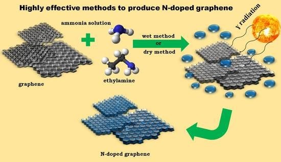
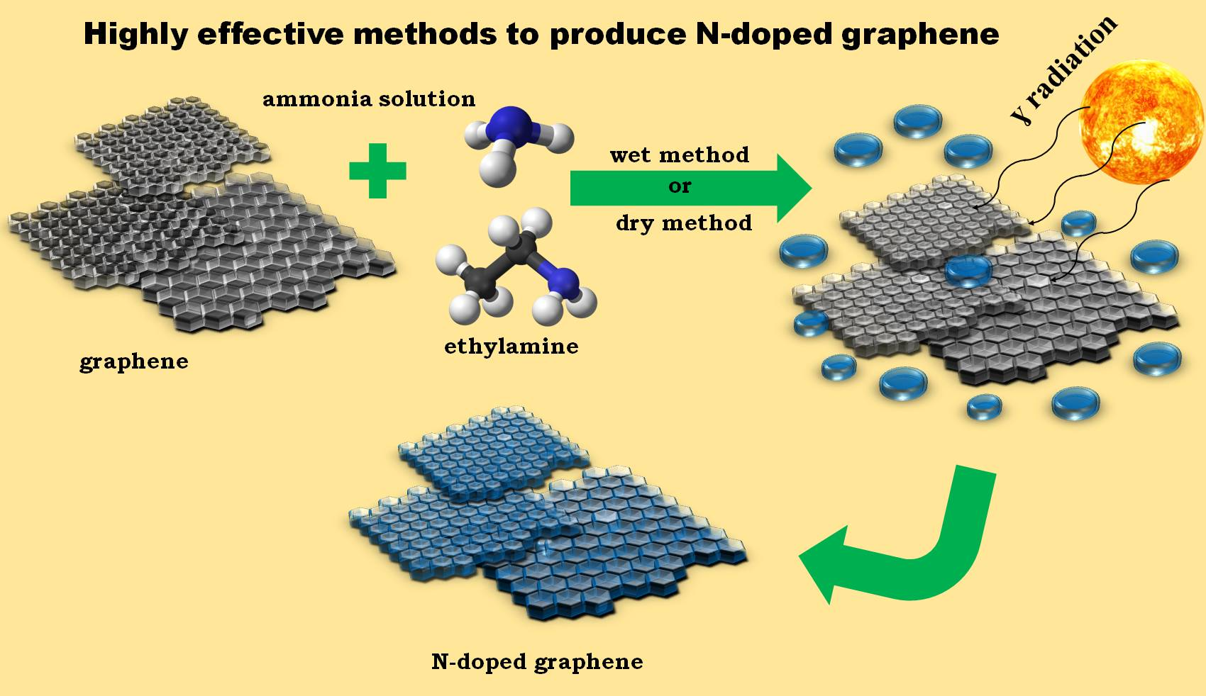
:The design and fabrication of a new effective manufacturing method of heteroatom-doped carbon materials is still ongoing. In this paper, we present alternative and facile methods to obtain N-rich graphene with the use of low energy gamma radiation. This method was used as a pure and facile method for altering the physical and chemical properties of graphene. The obtained materials have an exceptionally high N content—up to 4 wt %. (dry method) and up to 2 wt %. (wet method). High-resolution transmission electron microscopy (HRTEM), scanning electron microscopy (SEM), X-ray diffraction (XRD), Raman spectra and X-ray photoelectron spectroscopy (XPS) studies allowed us to evaluate the quality of the obtained materials. The presented results will provide new insights in designing and optimizing N-doped carbon materials potentially for the development of anode or cathode materials for electrochemical device applications, especially supercapacitors, metal–air batteries and fuel cells. Nitrogen atoms are exclusively bonded as quaternary groups. The method is expandable to the chemical insertion of other heteroatoms to graphene, especially such as sulfur, boron or phosphorus.
1. Introduction
Graphene has recently attracted the attention of the research society as well as industry circles. It belongs to the materials category called nano-carbons and particularly to the 2D class of materials. Theoretically, pristine graphene comprises only carbon atoms with some hydrogen atoms at the edge of each graphene plane. The description applies to paternal graphene planes as defined in the materials science encyclopedia and IUPAC documents [1,2]. However, such paternal graphene is hardly applicable in several technological fields despite its useful physicochemical features like chemical stability, excellent electric conductivity and high surface area [3]. Single-layered graphene (SLG) is an expensive material and very difficult to maintain. Therefore, from economic and practical point of view, instead of direct synthesis of SLG and its application, it is better to apply graphite (a 3D structure comprising plenty of parallel oriented and stack SLGs [2]. Utilization of features ascribed to SLG is the primary assumption of such research efforts aiming at graphite splitting to possibly single flakes of graphene. Graphite splitting/exfoliation is not an ideal process and delivers mixed forms regarding the separation degree [4]. Instead of SLG, other forms of graphene are privileged such as few-layered graphene (FLG) and multi-layered graphene (MLG); however, the application potential of these forms is also high [5]. Such forms of exfoliated graphene (SLG, FLG, MLG) may be subjected to further manipulations increasing its applicability in particular fields such as 3D structuring [6,7]. In parallel, graphene might be chemically modified by heteroatom insertion, mainly: oxygen, nitrogen, phosphorus, boron, sulfur, metal/metal oxide clusters. Nitrogen doping belongs to the most popular chemical modifications of graphene [8,9,10]. Generally, N doping is a common strategy for endowing new properties into a material, such as improving conductivity or constructing new bonds with other atoms [11,12,13]. Functional groups, including nitrogen-originated ones play a crucial role in the conversion of the non-polar surface of pristine graphene to the polar one since such introduced heteroatoms like O, S, N have considerably different electronegativity if compared to C atoms. Thus, upon N atom insertion, permanent charges get created on the surface, which are the source of attractive forces between the surface and the molecules (particularly polar) to be adsorbed on the surface. Therefore, N-modified carbon surfaces (as well as O-, S-modified) are naturally predestinated to the deposition of polar molecules and/or ions due to increased intermolecular attraction. The importance of such doping of diversified carbon materials is often presented regarding the application as electrode materials in electrochemical energy generation/storage devices like fuel cell, supercapacitors, metal–air batteries, and Li-ion batteries [14,15,16,17,18]. Additionally, N-modified carbon surfaces (including graphene) may serve as a platform for oligothiophene dyes deposition aiming at the manufacturing of usable photovoltaics materials [19]. Nitrogen-doped carbon materials inclusive of graphene provide high electrical conductivity in comparison to non-enriched ones. The chemically bonded nitrogen atoms play a double role: as an electron donor and are adsorption/catalytic centers of high basic nature (potential donor of an electron pair) [20]. Shifting of the Fermi level towards the conduction band is another effect commonly associated to the N-doping of semiconductor carbon matrixes. According to some studies [21], nitrogenation of carbon matrixes may also influence structural parameters such as pore size distribution and surface area. Usually N atoms substituted to carbon matrixes improve the pseudocapacitance of electrochemical energy storage devices [22].
Thus, facile and high-yield methods are explored for N insertion to carbon matrixes (especially graphene planes) since graphene’s chemical reactivity is limited. On the contrary to graphene oxidation, which is relatively easy to perform and has been known for a long time by standard wet chemistry oxidants like KMnO3 [23], the nitrogenation of graphene requires a more complex procedure and even sophisticated instruments. Several methods for the nitrogenation of graphite/graphene are commonly exploited [24,25,26] (Table 1).
The reviews on the synthesis of N-doped graphene covering the latest achievements, regardless of the place/date of publishing and the number of cited references, do not reveal any other nitrogen enrichment procedures except the “classical” ones (Table 1). The methods suffer from plenty of technological disadvantages, among which very low or low yield seems to be the main obstacle refraining industrial up scaling. Some methods rely on graphene oxide (GO) instead of pure graphene, which additionally limits their applicability since GO is another material that is different from graphene, i.e., GO has, for example, an inferior electric conductivity, which is a key property to be exploited when such materials are utilized for electrode design in electrochemical devices. To date, hundreds of authors whose papers have already been reviewed have mentioned the idea of nuclear radiation as factor triggering a direct reaction between graphene/graphite and a nitrogen source being in contact with the carbon matrixes. In fact, some publications have announced the applicability of gamma radiation to initiate a reaction between some solids and chemical modifiers (including graphene/graphite and their derivatives) as presented in Table 2. Even when citing more references, no trace can be found on the application of gamma radiation for triggering the reaction between graphene/graphite and gaseous/liquid nitrogen carries. In our opinion, there is no predecessor to the current study, of which the aim is to investigate the qualitative and quantitative effects of gamma-induced nitrification of graphene. The results will be compared to traditional nitrification findings (Table 1).
Heteroatom insertion in the case of graphene is particularly difficult due to a relatively high chemical energy. The process is much easier in the case of carbon materials of lower crystallinity (partly amorphous) like carbon black, pyrolytic chars and activated carbons, in which heteroatoms may appear due to their transfer from a source material upon carbonization. Another way of heteroatom insertion is based on the presence of some surface reactive centers on amorphous carbon surfaces (free radical, unsaturated valences etc.). Graphene hardly undergoes such heteroatom modification scenarios. Therefore, any method enabling the insertion of heteroatoms has a practical meaning. This fact points out the importance of the research concept presented in this paper.
2. Results and Discussion
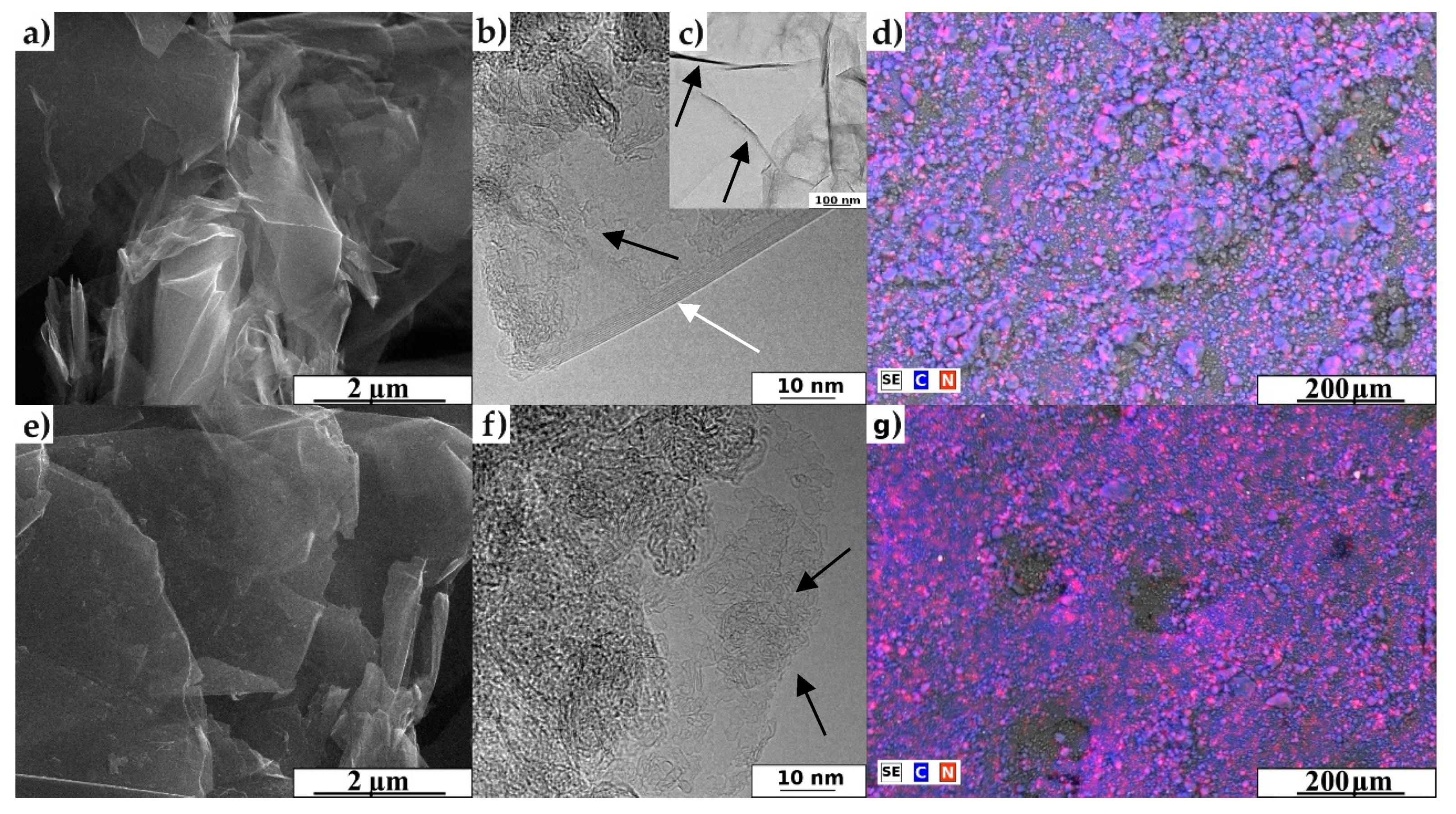
The morphology details of representative materials and pristine graphene nanoplatelets are shown in the SEM and HRTEM images (Figure 1). Figure 1a,e present the SEM images of GF_750_D_1D sample and GF_750_W_3D sample (please see the materials and methods section). The SEM images show several thin sheets. In particular, in Figure 1e, changes are clearly visible on the surface after the adsorption process using the wet method. Figure 1b,c,f present HRTEM images. In Figure 1b, a few layers of superimposed graphene (white arrow) are visible. Figure 1c shows the tinny and pure graphene nanoplatelets before the nitrogen introduction process. The graphene layers are clearly visible for all analyzed samples. The gamma irradiation did not destroy the original morphology of graphene nanoplatelets (the presented images are representatives for all performed tests). In turn, scanning electron microscopy with energy dispersive X-ray analysis (SEM/EDX) mapping images (Figure 1d,g) show the coverage of all carbon material with nitrogen, regardless of the used method. The analysis of all images (Figure 1) delivered direct proof of nitrogen presence and leads to the conclusion that the new proposed methods are highly effective to produce N-doped graphene.
The elemental composition for the N-doped graphene samples are given in Table 3. In general, nitrogen can positively influence the electric conductivity of graphene. Table 3 proves that the starting material, i.e., commercial graphene nanoplatelets is itself the source of small amount of nitrogen (below 0.8 wt.%). The elemental analysis revealed that the content of nitrogen in the proposed methods is up to 4 wt.%. In the dry method, when we increased the dose rate the nitrogen content decreased. The “dry method” was more effective regarding the intensity of N-doping, i.e., 4.19% of N was achieved for “dry method” in comparison to 2.00% of N for “wet method” (750 nanoplatelets). Moreover, the high content of 4.19% N was noted for a lower irradiation does collected in a shorter irradiation time of 14 days. The investigated N-doping methods “wet” and “dry” are characteristic because of saturation effect, i.e., N-content becomes stable or even starts to decrease after crossing a certain irradiation dose/irradiation time. Thus, in the “wet method” N-content increased constantly in order 1D –> 2D –> 3D for platelets of all types. In the “dry method”, the highest N-content was reached just after the dose 1D was accepted by the graphene samples. Then, the N-content remained stable or slightly decreased upon doses 2D and 3D.
Graphene nanoplatelets of the 750 kind are the most susceptible to N-doping by gamma radiation despite of the type of doping approach (“wet” or “dry”). The value 750 is the level of average surface area, which in this case is close to 750 m2/g. The high surface area is achieved due to the diminishing size of graphene plates (single and π-π stacked). Size diminishing means an increase in reactive centers located at the edges of graphene sheets. For smaller sheet the ratio: number of edge atom-to-mass is higher and therefore better for processes exploiting the reactivity of outer carbon atoms. Due to the same reasoning, the intensity of N-doping for the 150 nanoplatelets series (150 m2/g) is less spectacular. Elemental composition regarding C content in pristine (raw) nanoplatelets is inconsistent with their surface area. Lower C-content of 150/750 series in comparison to 300 series is a sign of the natural reactivity of the material exposed to air/oxygen even at room temperature. The highest C-content for 300 raw nanoplatelets is expectedly accompanied by the lowest O-content bonded to graphene planes as a result of a spontaneous reaction between carbon (graphene) and oxygen atoms (air).
Thus, the 300 platelets are the less reactive material among all graphene platelets under investigation. The assumed highest chemical stability for 300 nanoplatelets resulted in the lowest susceptibility to N-doping even in the experimental conditions conducive to chemical reaction (gamma irradiation).
The “wet” and “dry” methods differ because of the triggering of co-reactivity to oxygen. In both methods, oxygen is present in the reaction space: atmospheric oxygen (“dry” method) and water included oxygen (“wet” method). The mentioned difference applies to the case of the most reactive material, i.e., 750 nanoplatelets treated with 3D dose, where the oxygen content increased to the range of 12.395–14.72% O (“wet” method) from 11.09% O for pristine material. A similar phenomenon did not occur for “dry” method, when a slight decrease in O-content might be observed upon doses 1D, 2D and 3D.
All gamma radiation-treated samples are characteristic because of very high C-content, which is definitely better than that for graphene oxide (C/O 1.5–2.5). The C-to-O mass ratio is differentiated regarding the doping method and the nanoplatelets kind.
Raw graphene: 12—150 platelets, 85—300 platelets, 8—750 platelets.
“Dry” method: 16–85—150 platelets, 18–95—300 platelets, 8–9—300 platelets.
“Wet” method: 12–14—150 platelets, 13–45—300 platelets, 6–7—750 platelets.
C/O ratios for gamma irradiated 750 nanoplatelets (“dry” method) are on average similar to C/O ratios measured for pristine graphenes. C/O ratios for “wet” method modified platelets are the lower than for raw graphenes and lower than corresponding values for materials subjected to “dry” treatment. Thus, the “wet” method beside N-insertion doubtlessly leads to oxidation of graphene matrixes as a side (unwanted) effect.
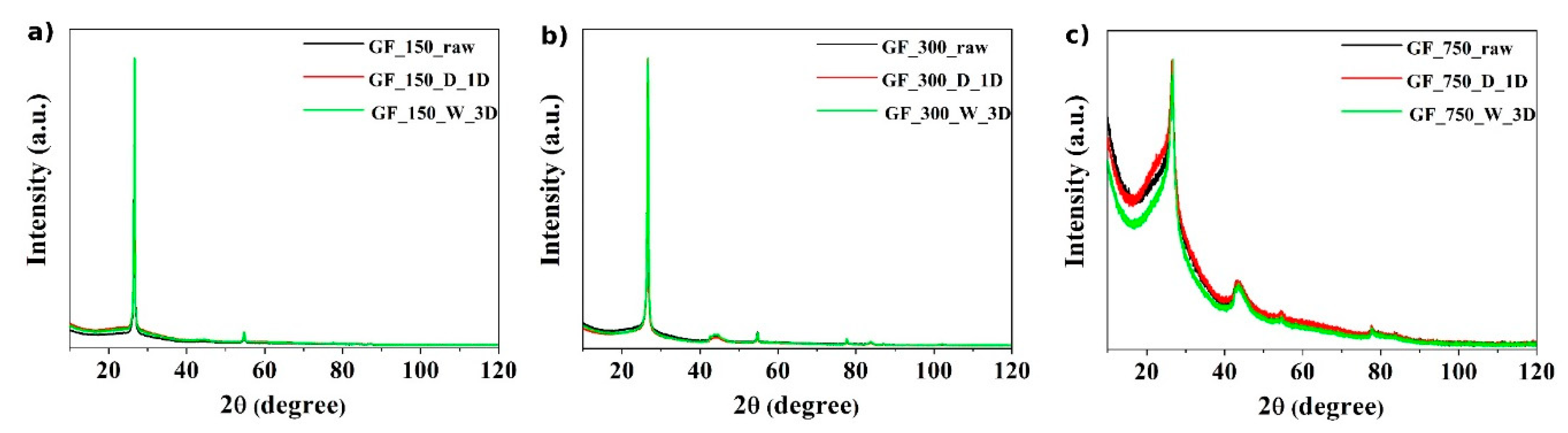
The XRD diffractograms of the obtained materials are shown in Figure 2. Sharp peaks in samples of the GF_150 and GF_300 series (Figure 2a,b) indicate an ordered and crystalline structure. In turn, for the GF_750 series (Figure 2c), the amorphous content is higher because the peaks are not so sharp. The structure of the used starting material affects the appearance of such XRD diffractograms. The crystal plane diffraction peak of the obtained materials appears at ~23° (002 reflection of graphitic carbon) and a smaller peak at ~44° (100 reflection of graphitic carbon) was determined.
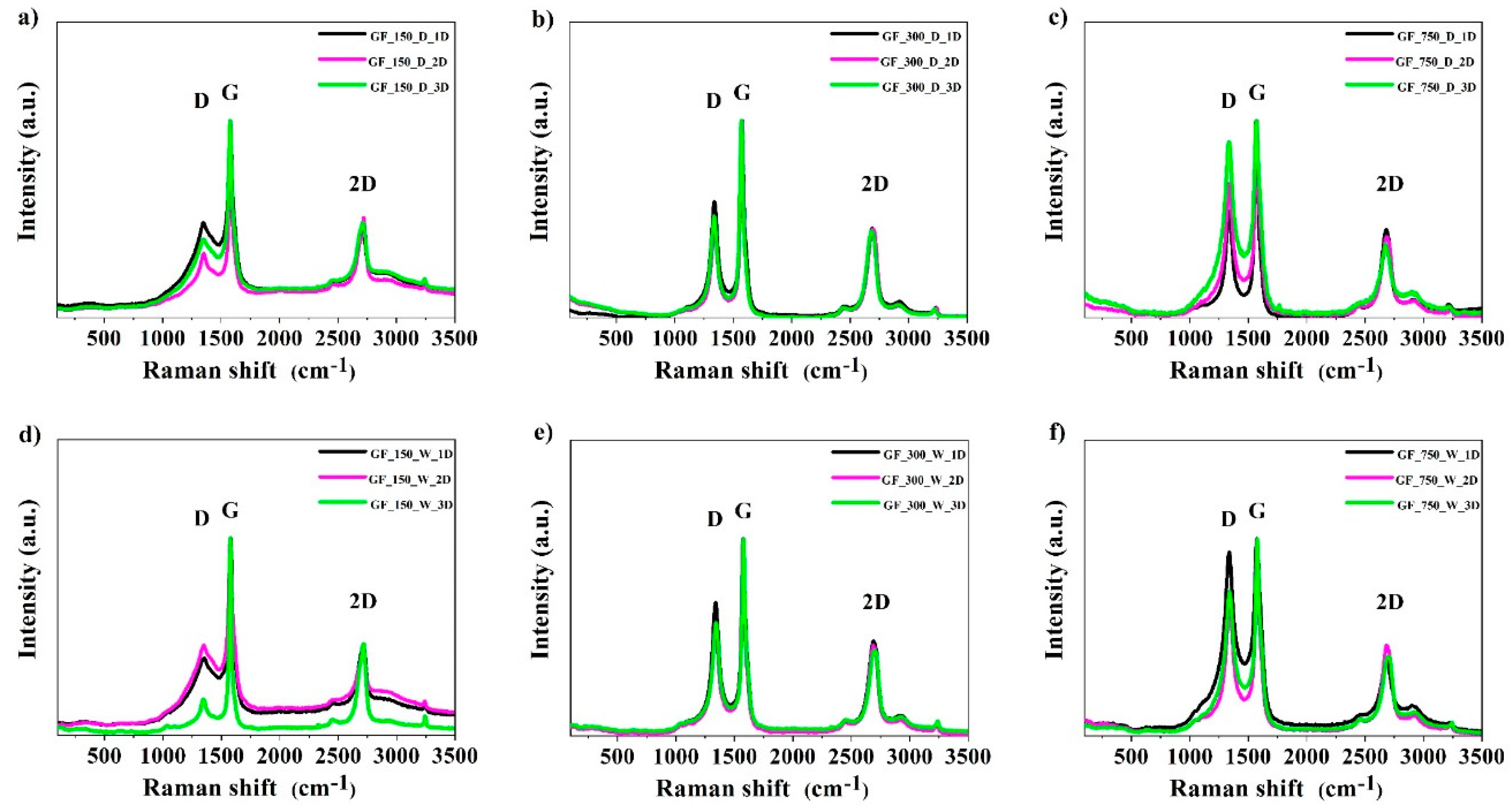
The Raman spectra (532 nm laser) of the obtained materials are shown in Figure 3. In graphite, a single sharp G peak is present at 1582 cm−1 and corresponds to the tangential vibrations of carbon atoms. Thus, G peak intensity may be a good measure of a sample’s graphitization. N-doped graphene exhibits two strong characteristic bands at 1340 cm−1 (D band) and 1580 cm−1 (G band). These bands are characteristic for graphene [38,43]. In turn, the 2D band is a characteristic peak of the graphene structure.
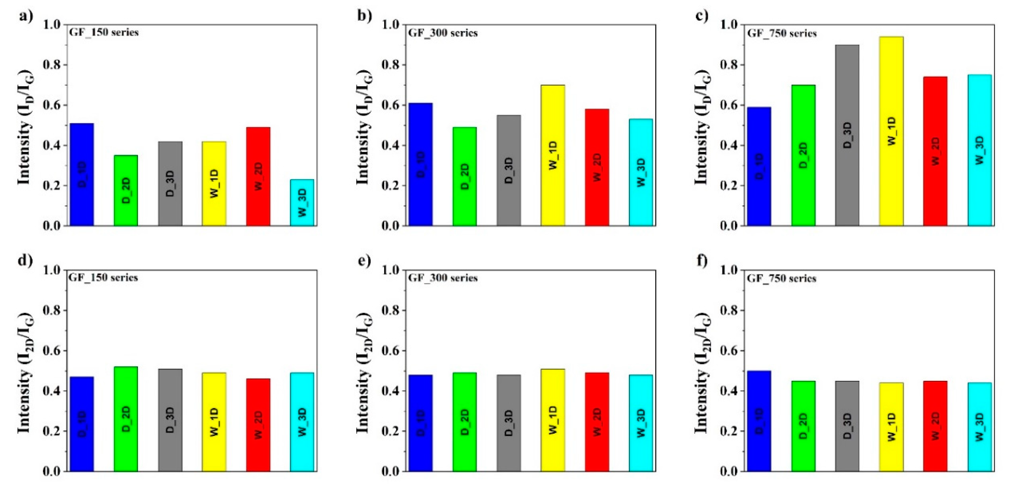
The ratio of the intensities between the D and G bands (ID/IG) depends on the level of the disorder. The ID/IG ratios for GF_150 series are between 0.23 and 0.50, for GF_300 series are between 0.45 and 0.70, and for GF_750 series are between 0.58 and 0.94, respectively, as shown in Figure 4. The increase in the ID/IG ratio clearly demonstrates the defects in the graphene structure. The differences in the ID/IG ratios for three obtained series confirm that the materials contain a different number of defects in the carbon structure.
According to Figure 4, the most defective structure with a higher degree of graphitization is exhibited by samples from the GF_750 series. The observed ratios of N-doped graphene in the second method are almost similar. In contrast, the I2D/IG ratio for all investigated series is in similar range between 0.40 and 0.50. It is known that the ratio I2D/IG of the intensity is dependent on the number of graphene layers. This ratio means that the obtained N-doped graphene structures are multilayers.
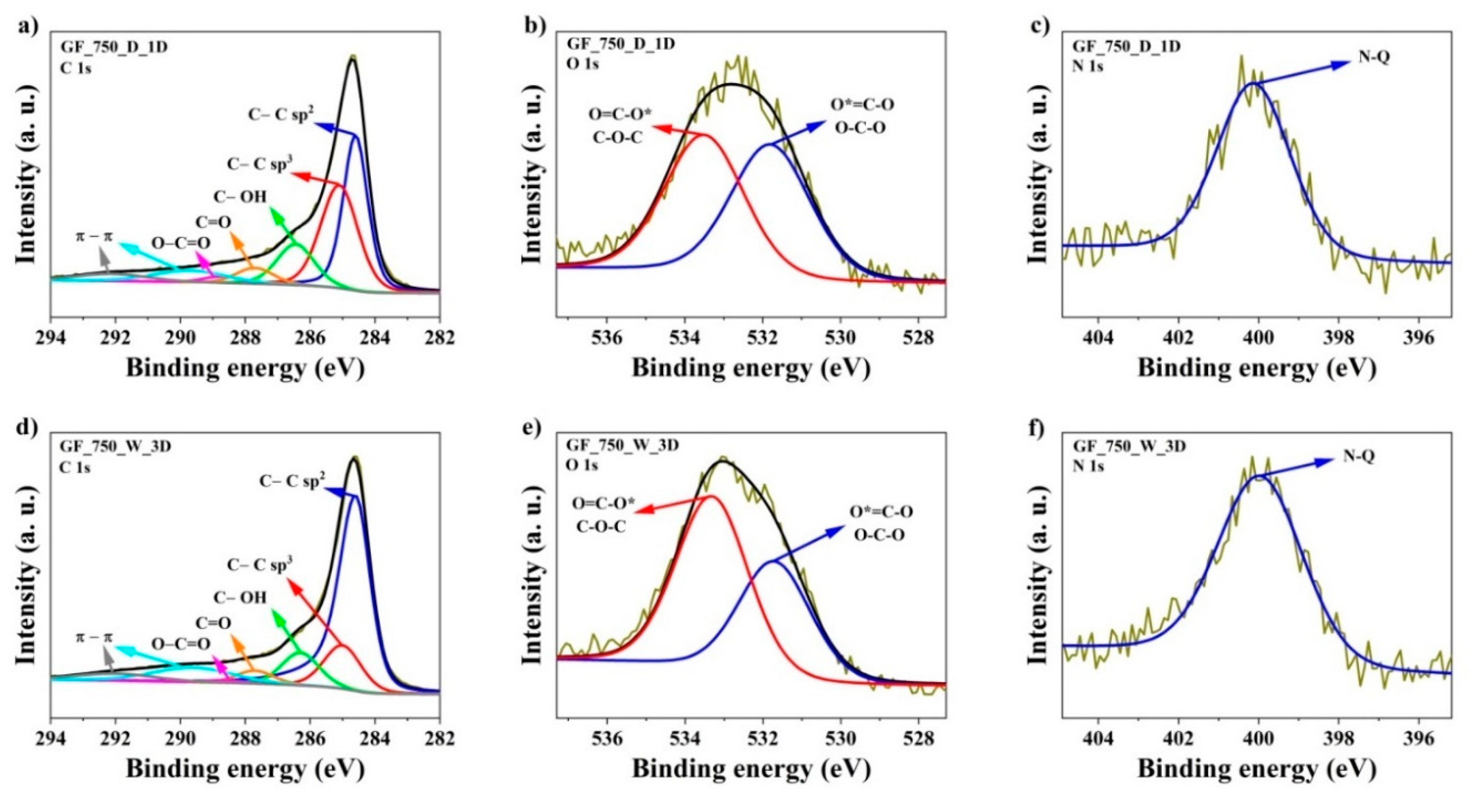
The results of a combustion elemental analysis allowed the determination of the overall bulk content of three principal elements: C, N and H, while the specific chemical environment of these elements and oxygen remains unknown. Therefore, the last conclusion is supported by X-ray photoelectron spectroscopy (XPS) investigations. Typical N-insertion methods reviewed in the introduction are characteristic because of diversification of N atoms bonding to graphene matrixes. Several structures are typically assumed: quaternary, pyridine, pyridone, amine, pyroll, imid, amid, lactam, among which quaternary groups are of primary importance for electrode-based applications (batteries, supercapacitors). XPS studies were aimed at the detection of the chemical environment of inserted N atoms.
The XPS spectra of the two representative samples of investigated series were determined and are demonstrated in Figure 5 and Table 4. The analysis of C1s energy is essential in determining the chemical bonding of carbon atoms. The elemental content of carbon was high, ranking from 92.2 to 96.1 at.% in samples of the wet method and from 90.9 to 96.6 at.% in samples of the dry method. Carbon atoms were mostly bonded as sp2 hybridized atoms (band C 1s at binding energy 284.6 eV), which is characteristic for graphene materials. The C1s spectra of N-doped graphene are composed of seven peaks corresponding to: C=C bond (sp2) peak at 284.6 eV [44], C–C bond (sp3) peak at 285 eV [44,45], C–O–C or C–OH or C–NH bond peak at 286.3 eV [40,41], C=O or O–C–O or N–C–O bond peak at 287.7 eV [44,45], O–C=O peak at 288.6 eV [44], and peaks with binding energy at 289.6 eV and 292.1 eV are associated with shake-up excitation [46]. The total amount of oxygen in samples of the wet method is in the range from 2.5 to 5.0 at.% and 2.4 to 5.3 at.% in the samples of the dry method, respectively. The peak at 532.0 eV signifies the presence of a O=C–N or C=O bond and the peak at 533.3 eV is characteristic of a O*=C–O or O–C–O bond [44,45,47]. In turn, the elemental content of nitrogen is in the range from 1.0 to 3.8 at.% for all proposed methods. The high-resolution N1s spectra can be deconvoluted into one peak, located at 400.5 eV, which is attributed to quaternary (N–Q) groups [44,45], respectively. The essence of the quaternary group is a cation consisting of a central positively charged atom with four substituents. It is known that the N–Q groups have a stronger donor electron character. This ability is important for electrochemical studies for the electron transfer, especially for the construction of electrodes in solar cells, supercapacitors or metal–air batteries [48,49,50,51,52,53].
Sliwak et al. [53] reported that a low oxygen content and the presence of stable quaternary nitrogen groups improved the charge propagation on the carbons. The presence of such an N–Q bond can facilitate the electron transfer and cause the enhancement of conductivity in carbons. XPS results confirmed the successive introduction of a high nitrogen content into the graphene structure. Regardless of the used methods, N-doped graphene containing nitrogen at a similar level was obtained.
Gamma irradiation causes the formation of reactive sites in the carbon matrix of an ionic and/or radical nature. In the obtained systems, the carbon matrix is directly enriched. This means that the enrichment of graphene in heteroelements can be obtained after the production of a porous graphene matrix. The proposed methods are characterized by a negligible consumption of reagents and a negligible amount of waste.
3. Materials and Methods
N-doped graphene was synthesized in two ways. In the first method called the “dry method”, 1g of graphene nanoplatelets (three different series, MO purchased from Sigma Aldrich were added to plastic test tubes and left open. The ethylamine (St. Louis, MO, USA) purchased from Sigma Aldrich was opened in a container containing ice. This was caused by the fact that the boiling point of this substance is 17 °C. Next, 10 mL of ethylamine was placed in a separate and open test tube. All test tubes were sealed in a square transparent plastic box. Then, we inserted the box into a radiation device. In the second method called the “wet method”, 1 g of graphene nanoplatelets (three different series) purchased from Sigma Aldrich were added to 100 mL PVC containers (Bionovo, Legnica, Poland). Next, we added 25 mL 6M NH3 aq (POCH, Gliwice, Poland) to each container and the contents were well mixed, and the containers were closed. Then, we inserted the containers into a radiation device.
Irradiation was carried out in a radiation device RChM-γ-20, where the source of gamma radiation is Co-60. The dosing rate during the experiments ranged from 19.3 to 21.0 Gy/h, average value ~20 Gy/h, determined using a Fricke dosimeter. Periodically, further samples were taken for analysis in a specified time schedule. After each irradiation step, the material was washed repeatedly with distilled water (2 L) using a Büchner funnel (Bionovo, Legnica, Poland) to remove all impurities, in particular, the residues of ethylamine and ammonia. Then, it was dried in an electric furnace at 150 °C for 24 h.
The N-doped graphene samples obtained by the proposed methods were denoted as GF_X_Y_ZD, where: e.g., GF_X means the type of used raw material (150—graphene nanoplatelets with an surface area of 150 m2/g; 300—graphene nanoplatelets with an surface area of 300 m2/g; 750—graphene nanoplatelets with an surface area of 750 m2/g), Y means the method used (D—dry method; W—wet method), and ZD means the dosing rate for dry method (1D—7.6 kGy; 2D—14.3 kGy; 3D—27.5 kGy) and for wet method (1D—5.5 kGy; 2D—14.6 kGy; 3D—20.9 kGy). GF_X_raw—means raw material before processing.
The morphology of the N-doped graphene was analyzed by scanning electron microscopy (SEM, 1430 VP, LEO Electron Microscopy Ltd., Oberkochen, Germany). The obtained materials were also examined by high-resolution transmission electron microscopy (HRTEM, FEI Europe production, model Tecnai F20 X-Twin, Brno, Czech Republic). The carbon materials obtained prior to the HRTEM microscopic analysis were dispersed in ethanol and treated with an Inter Sonic IS-1K bath for 15 min and deposited on holey carbon-coated copper grids. The volumetric elemental composition (carbon, nitrogen and hydrogen) of the materials was analyzed by means of a combustion elemental analyzer (Vario MACRO CHN, Elementar Analysensysteme GmbH, Langenselbold, Germany). Raman spectra were obtained by a micro-Raman spectrometer (laser wavelength 532 nm, Senterra, Bruker Optik, Billerica, MA, USA). The laser was tightly focused on the sample surface through a 50× microscope objective. To prevent any damage of the sample, excitation power was fixed at 2 mW. The resolution was 4 cm−1, CCD temperature 223 K, laser spot diameter 2.0 µm, and total integration time 100 s (50 × 2 s), were used. X-ray diffraction (XRD) patterns of the samples were obtained with an X-ray diffractometer (X’Pert-Pro, Philips, Cambridge, UK) equipped with a Cu Kα source at 40 kV and 30 mA. X-ray photoelectron spectroscopy (XPS, PHI5000 VersaProbe II Scanning XPS Microprobe, Chigasaki, Japan) measurements were performed using a monochromatic Al Kα x-ray source. Survey spectra were recorded for all samples in the energy range of 0 to 1300 eV with a 0.5 eV step, high-resolution spectra were recorded with a 0.1 eV step.
4. Conclusions
In summary, we have demonstrated new alternative methods and a low-cost strategy for obtaining N-rich graphene. The N-doped graphene was successfully prepared using gamma irradiation at a radiation dose lower than 30 kGy. The most efficient method is the “dry method” with the use of ethylamine, where the nitrogen content exceeds 4 wt.%. The irradiation method is very selective regarding the chemical form of inserted N atoms, which are exclusively bonded as quaternary groups, i.e., functional groups exceptionally useful for the improvement of such doped graphene electrodes in batteries and supercapacitors. On the contrary, traditional N-doping methods yield very diversified forms of N bonding, among which only few are expected to be used in the mentioned electrochemical applications. The proposed methods are a simple and universal option to the already known methods of introducing nitrogen and other heteroatoms, such as sulfur, boron or phosphorus.
This aspect of the performed study will be continued in further research. The future work should concentrate on two basic directions.
Firstly, the influence of raw graphene structure on the qualitative and quantitative effectiveness of N-enrichment should be investigated. In this study, mostly MLG was investigated which meant that any of the applied N-bearing reagents had limited access to the reactive centers induced by gamma radiation in the intrinsic spaces inside the MLG granules. The authors assume that there might be a substantial difference whether SLG, FLG or MLG is subjected to the nitrogen enrichment according to the radiation procedures presented in this study. The less agglomerated graphene precursors like SLG or FLG should react intensively, yielding graphene-based materials of a higher N content than in the case of MLG. For this purpose, several graphene splitting methods seem to applicable like electroexfoliation combined with the wet-chemistry exfoliation by means of polar aprotic liquids (acetone, NMP etc.). Intensively electroexfoliated graphene will be investigated as a continuation of the current study, which can serve as a reference point.
Secondly, the discovered unified chemical bonding of nitrogen to graphene matrix should result in the advancement of the electrochemical properties of them. Therefore, such gamma radiation-modified graphene-based materials should be evaluated electrochemically as an electrode material in some batteries such as metal–air ones. Oxygen reduction reaction (ORR) will be investigated aiming at the determination of cathodic properties of the materials.
Thirdly, there are neither theoretical nor experimental obstacles against nitrogen enrichment of other carbon-based materials like carbon nanotubes and even ordinary activated carbons. Nitrogen-rich activated carbons are still an emerging field in the search for effective electrode materials for plenty of electrochemical devices like metal–air batteries, supercapacitors, and fuel cells.
Author Contributions
Conceptualization, P.K. and J.P.L.; methodology, P.K. and J.P.L.; formal analysis, P.K., S.T. and J.P.L.; investigation, P.K., S.T. and J.P.L.; writing—original draft preparation, P.K. and J.P.L.; review and editing, P.K. and J.P.L.; visualization, P.K. and J.P.L.; supervision, J.P.L.; project administration, P.K. and J.P.L.; funding acquisition, J.P.L. All authors have read and agreed to the published version of the manuscript.
Funding
This work was supported by the National Science Centre (Poland) grant 2016/23/B/ST5/00658.
Acknowledgments
All experimental work (synthesis, analysis) was supported by the National Science Centre (Poland) grant 2016/23/B/ST5/00658.
Conflicts of Interest
The authors declare no conflict of interest.
References
- Wolf, E.L. Graphene. A New Paradigm in Condensed Matter and Device Physics; Oxford University Press: Oxford, UK, 2016. [Google Scholar]
- McNaught, A.D.; Wilkinson, A.; IUPAC. Compendium of Chemical Terminology; Blackwell Scientific Publications: Oxford, UK, 1997. [Google Scholar] [CrossRef]
- Guirguis, A.; Maina, J.W.; Zhang, X.; Henderson, L.C.; Kong, L.; Shon, H.; Dumee, L.F. Applications of nano-porous graphene materials-critical review on performance and challenges. Mater. Horiz. 2020, 7, 1218–1245. [Google Scholar] [CrossRef]
- Kamedulski, P.; Ilnicka, A.; Lukaszewicz, J.P. Selected Aspects of Graphene Exfoliation as an Introductory Step Towards 3D Structuring of Graphene Nano-Sheets. Curr. Graphene Sci. 2018, 2, 106–117. [Google Scholar] [CrossRef]
- Ilnicka, A.; Skorupska, M.; Kamedulski, P.; Lukaszewicz, J.P. Electro-Exfoliation of Graphite to Graphene in an Aqueous Solution of Inorganic Salt and the Stabilization of Its Sponge Structure with Poly (Furfuryl Alcohol). Nanomaterials 2019, 9, 971. [Google Scholar] [CrossRef] [PubMed] [Green Version]
- Hensleigh, R.M.; Cui, H.; Oakdale, J.S.; Ye, J.C.; Campbell, P.G.; Duoss, E.B.; Spadaccini, C.M.; Zheng, X.; Worsley, M.A. Additive manufacturing of complex micro-architected graphene aerogels. Mater. Horiz. 2018, 5, 1035–1041. [Google Scholar] [CrossRef] [Green Version]
- Kamedulski, P.; Ilnicka, A.; Lukaszewicz, J.P.; Skorupska, M. Highly effective three-dimensional functionalization of graphite to graphene by wet chemical exfoliation methods. Adsorption 2019, 25, 631–638. [Google Scholar] [CrossRef] [Green Version]
- Granzier-Nakajima, T.; Fujisawa, K.; Anil, V.; Terrones, M.; Yeh, Y.-T. Controlling Nitrogen Doping in Graphene with Atomic Precision: Synthesis and Characterization. Nanomaterials 2019, 9, 425. [Google Scholar] [CrossRef] [PubMed] [Green Version]
- Wang, H.; Maiyalagan, T.; Wang, X. Review on Recent Progress in Nitrogen-Doped Graphene: Synthesis, Characterization, and Its Potential Applications. ACS Catal. 2012, 2, 781–794. [Google Scholar] [CrossRef]
- Kaur, M.; Kaur, M.; Sharma, V.K. Nitrogen-doped graphene and graphene quantum dots: A review onsynthesis and applications in energy, sensors and environment. Adv. Colloid Interface Sci. 2018, 259, 44–64. [Google Scholar] [CrossRef] [PubMed]
- Xia, B.; Wang, T.; Jiang, X.; Li, J.; Zhang, T.; Xi, P.; Gao, D.; Xue, D. N+-ion irradiation engineering towards the efficient oxygen evolution reaction on NiO nanosheet arrays. J. Mater. Chem. A 2019, 7, 4729–4733. [Google Scholar] [CrossRef]
- Liu, P.; Ran, J.; Xia, B.; Xi, S.; Gao, D.; Wang, J. Bifunctional Oxygen Electrocatalyst of Mesoporous Ni/NiO Nanosheets for Flexible Rechargeable Zn-Air Batteries. Nano Micro Lett. 2020, 12, 1–12. [Google Scholar] [CrossRef] [Green Version]
- Xia, B.; Liao, Z.; Liu, Y.; Chi, X.; Xiao, W.; Ding, J.; Wang, T.; Gao, D.; Xue, D. Realization of “single-atom ferromagnetism” in graphene by Cu-N4 moieties anchoring. Appl. Phys. Lett. 2020, 116, 113102. [Google Scholar] [CrossRef]
- Kakaei, K.; Ghadimi, G. A green method for Nitrogen-doped graphene and its application for oxygen reduction reaction in alkaline media. Mater. Technol. 2020. [Google Scholar] [CrossRef]
- Sahoo, M.K.; Gogoi, P.; Rajeshkhanna, G.; Chilukuri, S.V.; Rao, G.R. Significance of optimal N-doping in mesoporous carbon framework to achieve high specific capacitance. Appl. Surf. Sci. 2017, 418, 40–48. [Google Scholar] [CrossRef]
- Wen, Z.; Wang, X.; Mao, S.; Bo, Z.; Kim, H.; Cui, S.; Lu, G.; Feng, X.; Chen, J. Crumpled nitrogen-doped graphene nanosheets with ultrahigh pore volume for high-performance supercapacitor. Adv. Mater. 2012, 24, 5610–5616. [Google Scholar] [CrossRef]
- Shao, Y.; Zhang, S.; Engelhard, M.H.; Li, G.; Shao, G.; Wang, Y.; Liu, J.; Aksay, I.A.; Lin, Y. Nitrogen-doped graphene and its electrochemical applications. J. Mater. Chem. 2010, 20, 7491–7496. [Google Scholar] [CrossRef]
- Bourquard, F.; Bleu, Y.; Loir, A.-S.; Caja-Munoz, B.; Avila, J.; Asensio, M.-C.; Raimondi, G.; Shokouhi, M.; Rassas, I.; Farre, C.; et al. Electroanalytical Performance of Nitrogen-Doped Graphene Films Processed in One Step by Pulsed Laser Deposition Directly Coupled with Thermal Annealing. Materials 2019, 12, 666. [Google Scholar] [CrossRef] [Green Version]
- Ilnicka, A.; Kamedulski, P.; Aly, H.M.; Lukaszewicz, J.P. Manufacture of activated carbons using Egyptian wood resources and its application in oligothiophene dye adsorption. Arab. J. Chem. 2020, 13, 5284–5291. [Google Scholar] [CrossRef]
- Choi, W.H.; Choi, M.J.; Bang, J.H. Nitrogen-Doped Carbon Nanocoil Array Integrated on Carbon Nanofiber Paper for Supercapacitor Electrodes. ACS Appl. Mater. Interfaces 2015, 7, 19370–19381. [Google Scholar] [CrossRef] [Green Version]
- Wei, J.; Zhou, D.; Sun, Z.; Deng, Y.; Xia, Y.; Zhao, D. A Controllable Synthesis of Rich Nitrogen-Doped Ordered Mesoporous Carbon for CO2 Capture and Supercapacitors. Adv. Funct. Mater. 2013, 23, 2322–2328. [Google Scholar] [CrossRef]
- Wu, K.; Liu, Q. Nitrogen-doped mesoporous carbons for high performance supercapacitors. Appl. Surf. Sci. 2016, 379, 132–139. [Google Scholar] [CrossRef]
- Hummers, W.S.; Offeman, R.E. Preparation of Graphitic Oxide. J. Am. Chem. Soc. 1958, 80, 1339. [Google Scholar] [CrossRef]
- Xu, H.; Ma, L. Nitrogen-doped graphene: Synthesis, characterizations and energy applications. J. Energy Chem. 2018, 27, 146–160. [Google Scholar] [CrossRef] [Green Version]
- Yadav, R.; Dixit, C.K. Synthesis, characterization and prospective applications of nitrogen-doped graphene: A short review. J. Sci. Adv. Mater. Devices 2017, 2, 141–149. [Google Scholar] [CrossRef]
- Zhuang, S.; Nunna, B.B.; Mandal, D.; Lee, E.S. A review of nitrogen-doped graphene catalysts for proton exchange membrane fuel cells-synthesis, characterization, and improvement. Nano Struct. Nano Objects 2018, 15, 140–152. [Google Scholar] [CrossRef]
- Luo, Z.; Lim, S.; Tian, Z.; Shang, J.; Lai, L.; MacDonald, B.; Fu, C.; Shen, Z.; Yu, T.; Lin, J. Pyridinic N doped graphene: Synthesis, electronic structure, and electrocatalytic property. J. Mater. Chem. 2011, 21, 8038–8044. [Google Scholar] [CrossRef]
- Lu, Y.-F.; Lo, S.-T.; Lin, J.-C.; Zhang, W.; Lu, J.-Y.; Liu, F.-H.; Tseng, C.-M.; Lee, Y.-H.; Liang, C.-T.; Li, L.-J. Nitrogen-Doped Graphene Sheets Grown by Chemical Vapor Deposition: Synthesis and Influence of Nitrogen Impurities on Carrier Transport. ACS Nano 2013, 7, 6522–6532. [Google Scholar] [CrossRef] [Green Version]
- Panchakarla, L.S.; Subrahmanyam, K.S.; Saha, S.K.; Govindaraj, A.; Krishnamurthy, H.R.; Waghmare, U.V.; Rao, C.N.R. Synthesis, Structure, and Properties of Boron- and Nitrogen-Doped Graphene. Adv. Mater. 2009, 21, 4726–4730. [Google Scholar] [CrossRef]
- Lin, Z.; Waller, G.; Liu, Y.; Liu, M.; Wong, C.-P. Facile synthesis of nitrogen-doped graphene via pyrolysis of graphene oxide and urea and its electrocatalytic activity toward oxygen reduction reaction. Adv. Energy Mater. 2012, 2, 884–888. [Google Scholar] [CrossRef]
- Sheng, Z.-H.; Shao, L.; Chen, J.-J.; Bao, W.-J.; Wang, F.-B.; Xia, X.-H. Catalyst-Free Synthesis of Nitrogen-Doped Graphene via Thermal Annealing Graphite Oxide with Melamine and Its Excellent Electrocatalysis. ACS Nano 2011, 5, 4350–4358. [Google Scholar] [CrossRef]
- Liu, Q.; Guo, B.; Rao, Z.; Zhang, B.; Gong, J.R. Strong two-photon-induced fluorescence from photostable, biocompatible nitrogen-doped graphene quantum dots for cellular and deep-tissue imaging. Nano Lett. 2013, 13, 2436–2441. [Google Scholar] [CrossRef]
- Li, X.; Wang, H.; Robinson, J.T.; Sanchez, H.; Diankov, G.; Dai, H. Simultaneous Nitrogen Doping and Reduction of Graphene Oxide. J. Am. Chem. Soc. 2009, 131, 15939–15944. [Google Scholar] [CrossRef] [Green Version]
- Li, X.; Geng, D.; Zhang, Y.; Meng, X.; Li, R.; Sun, X. Superior cycle stability of nitrogen-doped graphene nanosheets as anodes for lithium ion batteries. Electrochem. Commun. 2011, 13, 822–825. [Google Scholar] [CrossRef]
- Wang, Y.; Shao, Y.; Matson, D.W.; Li, J.; Lin, Y. Nitrogen-Doped Graphene and Its Application in Electrochemical Biosensing. ACS Nano 2010, 4, 1790–1798. [Google Scholar] [CrossRef]
- Ju, M.J.; Jeon, I.Y.; Kim, J.C.; Lim, K.; Choi, H.J.; Jung, S.M.; Choi, I.T.; Eom, Y.K.; Kwon, Y.J.; Ko, J. Graphene Nanoplatelets Doped with N at its Edges as Metal-Free Cathodes for Organic Dye-Sensitized Solar Cells. Adv. Mater. 2014, 26, 3055–3062. [Google Scholar] [CrossRef] [PubMed]
- Zhuang, S.; Nunna, B.B.; Boscoboinik, J.A.; Lee, E.S. Nitrogen-doped graphene catalysts: High energy wet ball milling synthesis and characterizations of functional groups and particle size variation with time and speed. Int. J. Energy Res. 2017, 41, 2535–2554. [Google Scholar] [CrossRef]
- Aujara, K.M.; Chieng, B.W.; Ibrahim, N.A.; Zainuddin, N.; Ratnam, C.T. Gamma-Irradiation Induced Functionalization of Graphene Oxide with Organosilanes. Int. J. Mol. Sci. 2019, 20, 1910. [Google Scholar] [CrossRef] [Green Version]
- Shlimak, I.; Zion, E.; Butenko, A.; Kaganovskii, Y.; Richter, V.; Sharoni, A.; Kogan, E.; Kaveh, M. Irradiation-induced metal-insulator transition in monolayer graphene. FlatChem 2019, 14, 100084. [Google Scholar] [CrossRef] [Green Version]
- Velo-Gala, I.; López-Peñalver, J.J.; Sánchez-Polo, M.; Rivera-Utrilla, J. Surface modifications of activated carbon by gamma irradiation. Carbon 2014, 67, 236–249. [Google Scholar] [CrossRef]
- Ansón-Casaos, A.; Puértolas, J.A.; Pascual, F.J.; Hernández-Ferrer, J.; Castell, P.; Benito, A.M.; Maser, W.K.; Martínez, M.T. The effect of gamma-irradiation on few-layered graphene materials. Appl. Surf. Sci. 2014, 301, 264–272. [Google Scholar] [CrossRef] [Green Version]
- Vega, E.; Sánchez-Polo, M.; Gonzalez-Olmos, R.; Martin, M.J. Adsorption of odorous sulfur compounds onto activated carbons modified by gamma irradiation. J. Colloid Interface Sci. 2015, 457, 78–85. [Google Scholar] [CrossRef]
- Nguyen, V.T.; Le, H.D.; Nguyen, V.C.; Ngo, T.T.T.; Le, D.Q.; Nguyen, X.N.; Phan, N.M. Synthesis of multi-layer graphene films on copper tape by atmospheric pressure chemical vapor deposition method. Adv. Nat. Sci. Nanosci. Nanotechnol. 2013, 4, 035012. [Google Scholar] [CrossRef]
- Beamson, G.; Briggs, D. High Resolution XPS of Organic Polymers: The Scienta ESCA300 Database. J. Chem. Educ. 1993, 70, A25. [Google Scholar]
- Rouxhet, P.; Genet, M. XPS analysis of bio-organic systems. Surf. Interface Anal. 2011, 43, 1453–1470. [Google Scholar] [CrossRef]
- Briggs, D. Surface Analysis of Polymers by XPS and Static SIMS; Cambridge University Press: New York, NY, USA, 2005. [Google Scholar]
- Genet, M.J.; Dupont-Gillain, C.C.; Rouxhet, P.G. XPS Analysis of Biosystems and Biomaterials. In Medical Applications of Colloids; Matijevic, E., Ed.; Springer Science Business Media LLC: New York, NY, USA, 2008. [Google Scholar]
- Hulicova-Jurcakova, D.; Seredych, M.; Lu, G.Q.; Bandosz, T.J. Combined Effect of Nitrogen- and Oxygen-Containing Functional Groups of Microporous Activated Carbon on its Electrochemical Performance in Supercapacitors. Adv. Funct. Mater. 2009, 19, 438–447. [Google Scholar] [CrossRef]
- Park, G.S.; Lee, J.-S.; Kim, S.T.; Park, S.; Cho, J. Porous nitrogen doped carbon fiber with churros morphology derived from electrospun bicomponent polymer as highly efficient electrocatalyst for Zn-air batteries. J. Power Sources 2013, 243, 267–273. [Google Scholar] [CrossRef]
- Ilnicka, A.; Skorupska, M.; Romanowski, P.; Kamedulski, P.; Lukaszewicz, J.P. Improving the Performance of Zn-Air Batteries with N-Doped Electroexfoliated Graphene. Materials 2020, 13, 2115. [Google Scholar] [CrossRef] [PubMed]
- Khamsanga, S.; Nguyen, M.T.; Yonezawa, T.; Thamyongkit, P.; Pornprasertsuk, R.; Pattananuwat, P.; Tuantranont, A.; Siwamogsatham, S.; Kheawhom, S. MnO2 Heterostructure on Carbon Nanotubes as Cathode Material for Aqueous Zinc-Ion Batteries. Int. J. Mol. Sci. 2020, 21, 4689. [Google Scholar] [CrossRef] [PubMed]
- Kamedulski, P.; Kaczmarek-Kedziera, A.; Lukaszewicz, J.P. Influence of intermolecular interactions on the properties of carbon nanotubes. Bull. Mater. Sci. 2018, 41, 76. [Google Scholar] [CrossRef] [Green Version]
- Sliwak, A.; Diez, N.; Miniach, E.; Gryglewicz, G. Nitrogen-containing chitosan-based carbon as an electrode material for high-performance supercapacitors. J. Appl. Electrochem. 2016, 46, 667–677. [Google Scholar] [CrossRef] [Green Version]
Figure 1.
Representative images of obtained samples: (a) SEM image of GF_750_D_1D sample, (b) HRTEM image of GF_750_D_1D sample, (c) HRTEM image of pristine GF_750_raw sample, (d) SEM/EDX mapping of GF_750_D_1D sample, (e) SEM image of GF_750_W_3D, (f) HRTEM image of GF_750_W_3D and (g) SEM/EDX mapping of GF_750_W_3D sample (arrows on the image 1c show pure and thin sheets).

Figure 2.
XRD images of three different series of obtained samples: (a) GF_150 series, (b) GF_300 series and (c) GF_750 series.
Figure 2.
XRD images of three different series of obtained samples: (a) GF_150 series, (b) GF_300 series and (c) GF_750 series.

Figure 3.
Raman spectra of all investigated series of the obtained samples: (a) GF_150_D series, (b) GF_300_D series, (c) GF_750_D_series, (d) GF_150_W series, (e) GF_300_W series and (f) GF_750_W series.
Figure 3.
Raman spectra of all investigated series of the obtained samples: (a) GF_150_D series, (b) GF_300_D series, (c) GF_750_D_series, (d) GF_150_W series, (e) GF_300_W series and (f) GF_750_W series.

Figure 4.
The ratio of the intensities between the D, G and 2D bands: (a) ID/IG of GF_150 D and W series, (b) ID/IG of GF_300 D and W series, (c) ID/IG of GF_750 D and W series, (d) I2D/IG of GF_150 D and W series, (e) I2D/IG of GF_300 D and W series and (f) I2D/IG of GF_750 D and W series.
Figure 4.
The ratio of the intensities between the D, G and 2D bands: (a) ID/IG of GF_150 D and W series, (b) ID/IG of GF_300 D and W series, (c) ID/IG of GF_750 D and W series, (d) I2D/IG of GF_150 D and W series, (e) I2D/IG of GF_300 D and W series and (f) I2D/IG of GF_750 D and W series.

Figure 5.
High-resolution X-ray photoelectron spectra for C1s, N1s, and O1s of representative samples: (a) C1s of GF_750_D_1D, (b) O1s of GF_750_D_1D, (c) N1s of GF_750_D_1D, (d) C1s of GF_750_W_3D, (e) O1s of GF_750_W_3D and (f) N1s of GF_750_W_3D.
Figure 5.
High-resolution X-ray photoelectron spectra for C1s, N1s, and O1s of representative samples: (a) C1s of GF_750_D_1D, (b) O1s of GF_750_D_1D, (c) N1s of GF_750_D_1D, (d) C1s of GF_750_W_3D, (e) O1s of GF_750_W_3D and (f) N1s of GF_750_W_3D.


Table 1.
An overview of currently practiced methods for nitrogen insertion into graphene.
| Method | Description | Drawbacks | Example Study |
|---|---|---|---|
| CVD | High temperature furnace up to 1000 °C, vacuum 1 Torr, catalyst, NH3 as nitrogen source, He as shielding gas | Complex instrumentation, very low yield | [27,28] |
| Arc Discharge | Electric arc discharge conditions, pyridine and ammonia as a nitrogen carrier | Complex instrumentation, difficult to control, very low yield | [29] |
| Pyrolysis | High temperature pyrolysis of a stolid mixture of GO—urea lattice, respectively | Limited yield, long time high temperature synthesis, application of GO instead of pure graphene | [30] |
| Heat treating | Heating to 800–1000 °C a solid mixture of GO-nitrogen source, neutral atmosphere, melamine as a potential nitrogen source | [31] | |
| Solvothermal | 200–300 °C, 4–5 h duration, dimethylformamide as a solvent and nitrogen source | Yield limited by the experimental vessel volume, use environmentally and health unfriendly reagents | [32] |
| Gas Annealing | High temperature of 500–1000 °C during electrical annealing of GO in nitrogen atmosphere, ammonia gas (NH3) as a nitrogen source | GO applied instead of pure graphene/graphite, low yield, a high temperature method | [33,34] |
| N2 Plasma Treatment | Nitrogen content controlled by the plasma strength and exposure time, example plasma generator parameters 40–200 W, 900 V DC bias, high vacuum 200 mTorr, 20–80 min treatment, graphene or GO as a key precursor, N2 and NH3 as nitrogen source | Sophisticated instrumentation and challenging synthesis conditions, low yield | [35] |
| Dry Ball Milling | Mechanochemical process, room temperature direct grinding of dry powdered graphite in the N2 or NH3 atmosphere, nitrogen content controllable by changing milling parameters | Unwanted insertion of impurities from the grinding setup, which must be removed by additional treatment, laboratory scale process | [36] |
| Nanoscale High Energy Wet Ball Milling | Mechanochemical process, room to 80 °C wet milling; gas, liquid and solid nitrogen carriers permittable, GO advised as carbon precursor | Complex manufacturing pathway including frequent rising, laboratory scale process | [37] |
Table 2.
Example application of gamma radiation for physical and chemical modification of carbon-type materials.
Table 2.
Example application of gamma radiation for physical and chemical modification of carbon-type materials.
| Experiment Description | Example Study |
|---|---|
| Gamma-ray radiation for altering of physicochemical properties of graphene oxide (GO) by insertion of aminosilanes | [38] |
| Metal-to-insulator transition of monolayered graphene | [39] |
| Changing activated carbon surface upon gamma irradiation in the presence of pure and contaminated water | [40] |
| The effect of gamma irradiation on the structure and composition of chemically synthesized few-layered graphene-based materials | [41] |
| Surface activation of commercial activated carbon induced by gamma radiation and the applicability of modified carbon for the removal of odors | [42] |
Table 3.
Elemental composition of obtained N-doped graphene.
| Method | Sample | Elemental Analysis (wt.%) | |||
|---|---|---|---|---|---|
| N | C | H | Residuals (Oxygen) | ||
| GF_150_raw | 0.61 | 90.77 | 0.90 | 7.72 | |
| GF_300_raw | 0.34 | 98.04 | 0.47 | 1.15 | |
| GF_750_raw | 0.72 | 87.32 | 0.87 | 11.09 | |
| dry | GF_150_D_1D | 2.19 | 90.79 | 1.55 | 5.47 |
| GF_150_D_2D | 2.14 | 91.88 | 1.63 | 4.35 | |
| GF_150_D_3D | 2.09 | 94.92 | 1.83 | 1.16 | |
| GF_300_D_1D | 1.66 | 93.68 | 0.88 | 3.78 | |
| GF_300_D_2D | 1.66 | 92.44 | 0.85 | 5.05 | |
| GF_300_D_3D | 1.66 | 96.35 | 0.96 | 1.03 | |
| GF_750_D_1D | 4.19 | 83.95 | 1.64 | 10.22 | |
| GF_750_D_2D | 4.03 | 84.66 | 1.55 | 9.76 | |
| GF_750_D_3D | 4.01 | 83.42 | 1.71 | 10.86 | |
| wet | GF_150_W_1D | 0.62 | 90.52 | 1.15 | 7.71 |
| GF_150_W_2D | 1.29 | 90.77 | 1.36 | 6.58 | |
| GF_150_W_3D | 1.38 | 89.84 | 1.11 | 7.67 | |
| GF_300_W_1D | 0.77 | 91.85 | 0.68 | 6.70 | |
| GF_300_W_2D | 0.98 | 95.70 | 0.72 | 2.60 | |
| GF_300_W_3D | 1.17 | 96.13 | 0.54 | 2.16 | |
| GF_750_W_1D | 1.52 | 82.85 | 0.91 | 14.72 | |
| GF_750_W_2D | 1.98 | 84.12 | 1.51 | 12.39 | |
| GF_750_W_3D | 2.00 | 84.27 | 1.23 | 12.50 | |
Table 4.
Elemental composition of the obtained N-doped graphene from the XPS spectra.
| Element | C | O | N | |||||||||
|---|---|---|---|---|---|---|---|---|---|---|---|---|
| Binding Energy (eV) | 284.6 | 285.0 | 286.3 | 287.7 | 288.6 | 289.6 | 292.1 | % of Total | 532.0 | 533.3 | % of Total | 400.5 |
| Sample | Content (at.%) | Content (at.%) | Content (at.%) | |||||||||
| GF_150_D_1D | 52.8 | 23.9 | 7.4 | 2.8 | 1.2 | 5.1 | 3.4 | 96.6 | 1.0 | 1.4 | 2.4 | 1.0 |
| GF_150_W_3D | 60.8 | 13.9 | 6.5 | 2.7 | 0.3 | 6.7 | 4.8 | 95,7 | 1.6 | 1.5 | 3.1 | 1.2 |
| GF_300_D_1D | 45.5 | 23.2 | 9.8 | 3.8 | 2.0 | 6.7 | 4.5 | 95.5 | 1.6 | 1.5 | 3.1 | 1.4 |
| GF_300_W_3D | 54.1 | 17.3 | 7.8 | 3.5 | 0.1 | 8.0 | 5.3 | 96.1 | 1.0 | 1.5 | 2.5 | 1.4 |
| GF_750_D_1D | 28.3 | 34.5 | 10.8 | 4.8 | 3.2 | 5.6 | 3.7 | 90.9 | 2.8 | 2.5 | 5.3 | 3.8 |
| GF_750_W_3D | 52.8 | 12.4 | 9.3 | 3.7 | 0.8 | 8.9 | 4.3 | 92.2 | 2.0 | 3.0 | 5.0 | 2.8 |
Publisher’s Note: MDPI stays neutral with regard to jurisdictional claims in published maps and institutional affiliations. |
© 2020 by the authors. Licensee MDPI, Basel, Switzerland. This article is an open access article distributed under the terms and conditions of the Creative Commons Attribution (CC BY) license (http://creativecommons.org/licenses/by/4.0/).
Share and Cite
MDPI and ACS Style
Kamedulski, P.; Truszkowski, S.; Lukaszewicz, J.P. Highly Effective Methods of Obtaining N-Doped Graphene by Gamma Irradiation. Materials 2020, 13, 4975. https://0-doi-org.brum.beds.ac.uk/10.3390/ma13214975
AMA Style
Kamedulski P, Truszkowski S, Lukaszewicz JP. Highly Effective Methods of Obtaining N-Doped Graphene by Gamma Irradiation. Materials. 2020; 13(21):4975. https://0-doi-org.brum.beds.ac.uk/10.3390/ma13214975
Chicago/Turabian StyleKamedulski, Piotr, Stanislaw Truszkowski, and Jerzy P. Lukaszewicz. 2020. "Highly Effective Methods of Obtaining N-Doped Graphene by Gamma Irradiation" Materials 13, no. 21: 4975. https://0-doi-org.brum.beds.ac.uk/10.3390/ma13214975
Note that from the first issue of 2016, this journal uses article numbers instead of page numbers. See further details here.