Comparing Rubber Bearings and Eradi-Quake System for Seismic Isolation of Bridges


1
Department of Infrastructure Safety Research, Korea Institute of Civil Engineering and Building Technology, Goyang 10223, Korea
2
School of Agricultural Civil & Bio-industrial Engineering, Kyungpook National University, Daegu 41566, Korea
*
Author to whom correspondence should be addressed.
Materials 2020, 13(22), 5247; https://0-doi-org.brum.beds.ac.uk/10.3390/ma13225247
Submission received: 19 October 2020
/
Revised: 10 November 2020
/
Accepted: 16 November 2020
/
Published: 20 November 2020
(This article belongs to the Special Issue Advances in Construction and Building Materials)
Abstract
:Seismic isolation systems have been used worldwide in bridge structures to reduce vibration and avoid collapse. The seismic isolator, damper, and Shock Transmission Unit (SUT) are generally adopted in the seismic design of bridges to improve their seismic safety with economic efficiency. There are several seismic isolation systems, such as Natural Rubber Bearing (NRB), Lead Rubber Bearing (LRB), and the Eradi-Quake System (EQS). EQS as a new technology is expected to effectively reduce both seismic force and displacement, but there is still some need to verify whether it might provide an economical and practical strategy for a bridge isolation system. Moreover, it is important to guarantee consistent performance of the isolators by quality control. A comparative evaluation of the basic properties of the available seismic isolators is thus necessary to achieve a balance between cost-effectiveness and the desired performance of the bridge subjected to extreme loading. Accordingly, in this study, the seismic response characteristics of the seismic isolation systems for bridges were investigated by conducting compressive test and compressive-shear test on NRB, LRB, and EQS.
1. Introduction
1.1. General
Seismic isolation systems such as the seismic isolator, damper, and Shock Transmission Unit (SUT) have been widely used in bridge structures to reduce vibration, prevent collapse, and improve seismic safety with economic efficiency. Among these systems, the seismic isolation bearing or seismic isolator allows the structure to behave more flexibly with enhanced seismic response by decoupling the superstructure from the foundation and providing additional damping. The isolators are laterally flexible elements but can carry the vertical loads of the overlying structure. Since the isolators are more flexible than the structure, most of the lateral movements caused by the earthquake occur in the isolators which make the isolated structure experience less motion and reduced forces. Compared to a traditional non-isolated structure, seismic isolation can reduce the forces and displacements in the structure by up to 75% that allow the structure to remain functional with less or no damage. The cost saving brought by the seismic isolation is achieved by the possibility to reduce the dimensions of the foundation by dropping the elastic forces down by up to 75% in the design [1,2,3,4].
There are several seismic isolation systems such as Natural Rubber Bearing (NRB), Lead Rubber Bearing (LRB), and Eradi-Quake System (EQS). EQS as a new technology has been proven to effectively reduce both seismic force and displacement [5,6,7,8], but there is still the need to verify whether it might provide an economical and practical strategy for bridge isolation systems. Moreover, it is important to guarantee consistent performance of the isolators by quality control. A comparative evaluation of the basic properties of the available seismic isolators is thus necessary to achieve a balance between cost-effectiveness and the desired performance of the bridge subjected to extreme loading. Accordingly, in this study, the seismic response characteristics of the seismic isolation systems are investigated by conducting a compressive test and compressive-shear test on NRB, LRB, and EQS.
1.2. Elastomeric Bearings
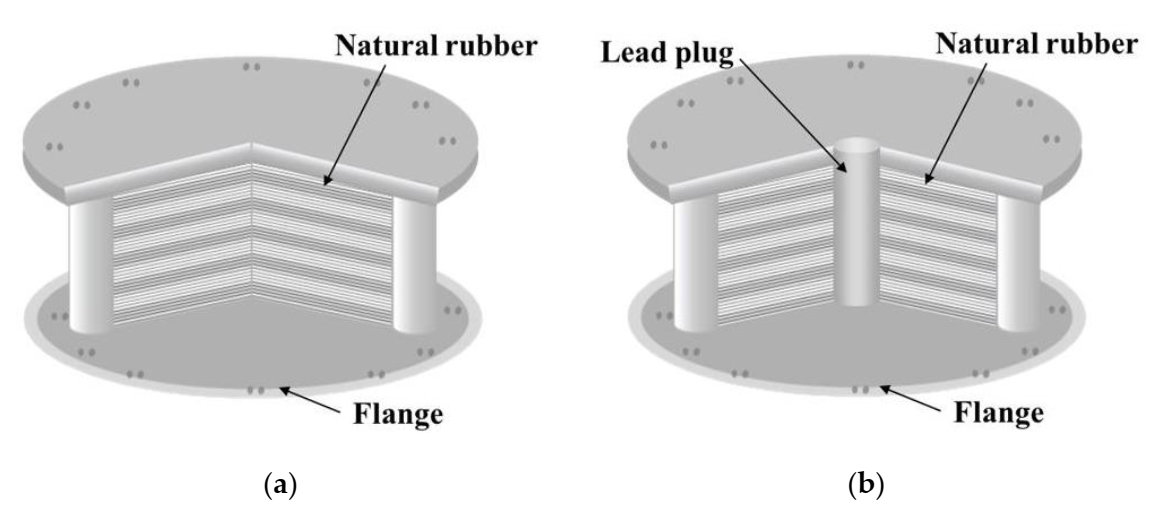
The concept of base isolation is quite simple. The system decouples the structure from the horizontal components of the ground motion by interposing structural elements with low horizontal stiffness between the structure and the foundation [9]. The first use of a rubber isolation system to protect a structure from earthquakes happened in 1969 for an elementary school in Skopje, Yugoslavia [10]. Based on their main properties and composition, there are two types of elastomeric bearings: NRB (Figure 1a) and LRB (Figure 1b).
NRBs are made of alternating steel shims vulcanized or glued together and elastomeric layers which provide lateral flexibility and elastic restoring force. The steel plates reinforce the bearing by providing vertical load capacity and preventing lateral bulge. A rubber cover protects the ensemble. Mounting plates connect the device to the structure above and below. Depending on the elastomeric compounds used, NRBs are available as either low damping or high damping. Low damping NRBs are used in conjunction with supplementary damping devices, whereas high damping NRBs can be used without other devices since they provide sufficient inherent damping [3,9,11,12,13,14]. LRBs are similar to NRBs but contain a lead core. The steel shims confine the lead plug and force it to deform in shear. Along with this deformation, dissipation of energy takes place.
1.3. EQS
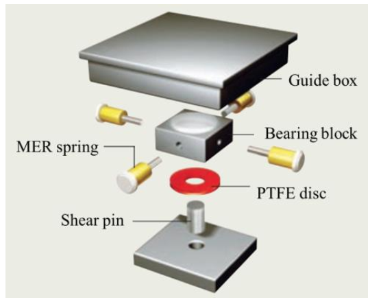
EQS is an innovative sliding-type seismic isolation bearing system designed to minimize forces and displacements experienced by structures subjected to seismic load. As shown in Figure 2, its components consist of top and bottom plates which are fixed to the superstructure and substructure of the bridge, respectively. In the bottom plate, a Poly Tetra Fluoro Ethylene (PTFE) friction disc, which has a primary stiffness, performs friction damping and dissipates seismic energy with resistant force caused by its sliding resilient friction. The lateral Mass Energy Regulator (MER) springs that supply restoring forces primarily reposition the plate back to its original position after finishing displacement responses. EQS transfers the seismic energy into heat and spring energy through friction of a PTFE disc pad and MER [2,6,7,8,15,16,17,18,19,20,21]. Whereas the rubber bearings exhibit relatively significant dispersion in their mechanical parameters, EQS can be tuned to the desired level of stiffness and damping, and generally has a force–displacement relationship presenting post-yield stiffness-hardening during large inelastic displacement.
2. Experimental Program
2.1. Design Properties of Test Specimens
The seismic resistance of NRB, LRB, and EQS was evaluated experimentally on a total of seven specimens (NRB: 3 specimens, LRB: 3 specimens, EQS: 1 specimen). Table 1 lists the properties of the NRB and LRB specimens where d is the diameter of rubber; Pv is the vertical load bearing capacity; G is the shear modulus; Kv and Kh are the vertical and horizontal stiffnesses, respectively; Py is the yield strength; EDC is the energy dissipated per cycle, which is the energy dissipation capacity of the isolator when it displays a reciprocating motion under seismic load; and Pb is the buckling load. For further comparison, the NRB and LRB specimens were designed to sustain the same Pv of 2945 kN and have the same diameter and shear modulus. Table 2 arranges the design properties of the EQS specimens designed for Pv = 2775 kN and design maximum displacement (dmax) of 50 mm. In Table 2, Ldead, Llive, and L are the design dead load, the design live load, and design load, respectively. In addition, fmax is the coefficient of friction of the PTFE disc at high velocity of sliding, and fmin is the coefficient of friction at essentially zero velocity of sliding. Keff denotes the effective stiffness.
2.2. Testing Method and Setup
2.2.1. Compressive Load Test
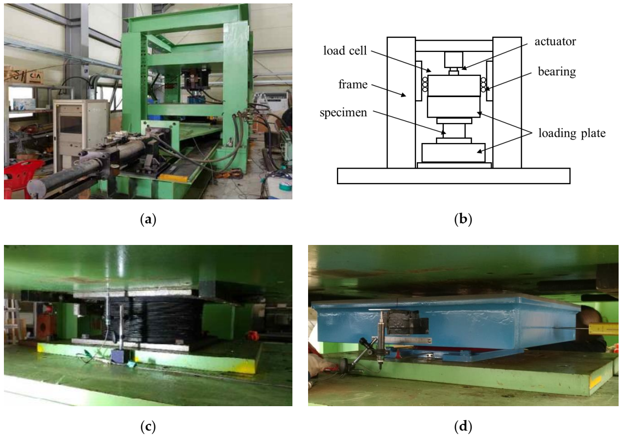
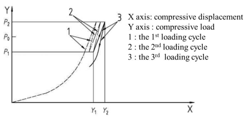
The setup adopted for the compressive test is illustrated in Figure 3. Biaxial loading was applied using two hydraulic actuators. The vertical actuator (Samyeon Tech, Daegu, Korea) with a capacity of 3500 kN and the horizontal actuator (Samyeon Tech, Daegu, Korea) with a horizontal capacity of 500 kN are components of the testing machine and can be extended up to 150 and 600 mm, respectively. A Linear Variable Displacement Transducer (LVDT) (Samyeon Tech, Daegu, Korea) was installed to measure the biaxial displacements, as depicted in Figure 3c for the NRB and LRB specimens and Figure 3d for the EQS specimens. The loading details are explained in Figure 4 and Table 3. The design vertical load (p0) was 2000 kN for LRB and NRB, and 1850 kN for EQS. The compressive loads were imparted three times on the specimens within a range between p1 and p2, which are 70% and 130% of the design vertical load. The compressive stiffness, Kv, can be calculated by Equation (1) with the test data, p1, p2, Y1, and Y2, where Y1 and Y2 are the horizontal displacements corresponding to p1 and p2, respectively, as shown in Figure 4. Moreover, the compressive stresses, and can be calculated by Equations (2) and (3) using the compressive loads, p1 and p2.
where is the net loading area excluding the area of the lead core in the LRB specimens.
2.2.2. Compressive-Shear Test
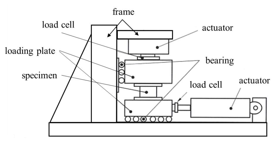
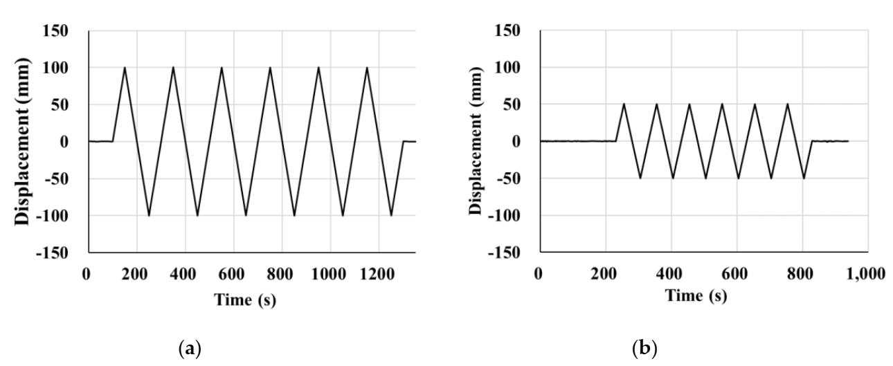
The specimens were tested according to the test guidelines for bridge isolators [22] developed by the Korea Institute of Civil Engineering and Building Technology (KICT) using a compressive-shear testing machine (Samyeon Tech, Daegu, Korea), the conceptual drawing of which is shown Figure 5. The shear force and the horizontal displacement were measured under constant vertical load. During the testing, the loading plates should be parallel to each other and the actuator must apply a constant vertical load when the height of the specimen is changed. The lateral (shear) loading history is shown in Figure 6. The shear stiffness and the equivalent damping can be calculated using the measured test results. The shear force measured by a horizontally installed load cell had to be calibrated after the test because the friction force of the testing machine was added to the measured load, even though the bearings were installed to reduce such friction of the machine.
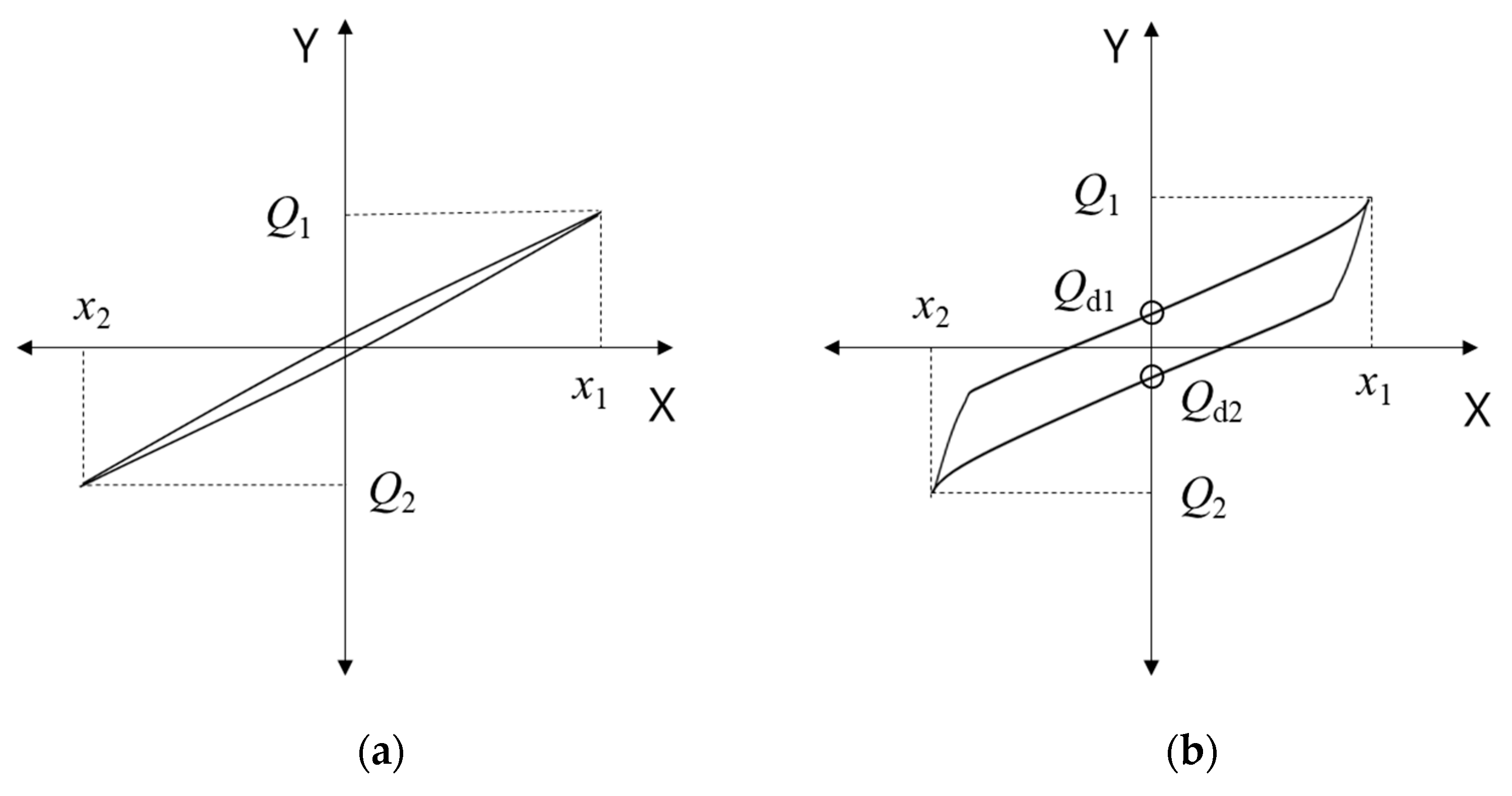
Figure 7 shows the theoretical shear behaviors of NRB, LRB, and EQS isolators, where X and Y denote the lateral (shear) displacement and the lateral (shear) load applied by the actuator, respectively. In Figure 7a, representing the hysteresis of NRB, the isolator shows quasi-linear behavior. In Figure 7b, representing the shear behavior of LRB and EQS, the area enclosed in the hysteresis is larger owing to the additional damping brought by these two types of isolators.
The shear stiffness () and equivalent damping () can be derived by Equations (4) and (5) using the test results.
where and are the maximum and minimum shear forces, respectively; and are the maximum and minimum displacements corresponding to and , respectively; and is the area enclosed by the hysteresis curve and represents the energy absorbed by the isolator.
3. Test Results and Discussion
3.1. Compressive Load Test Results
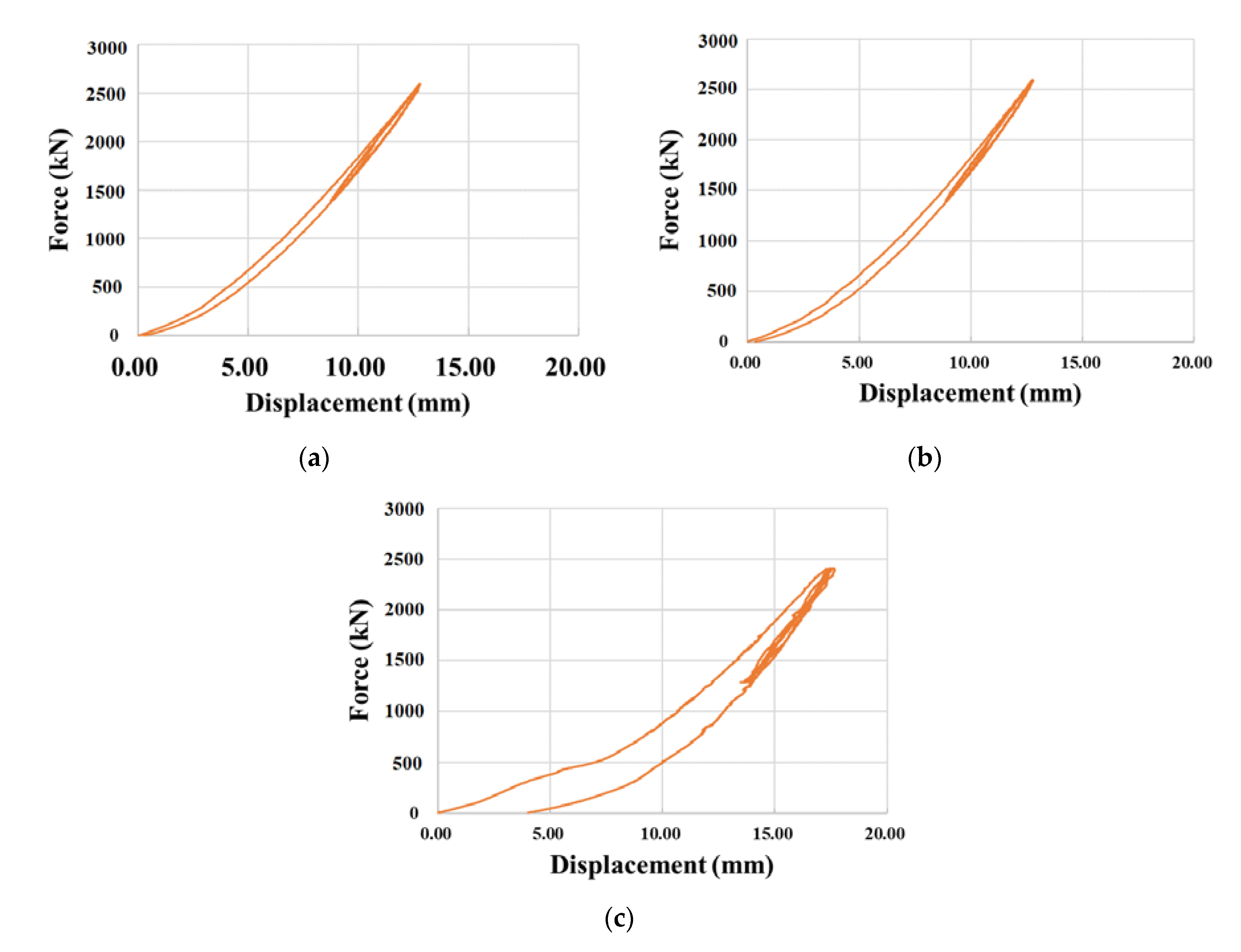
All the specimens were first loaded monotonically until the design vertical load (p0), and then cyclic compressive load was applied three times with a range between 70% (p1) and 130% (p2) of the design vertical load. Table 4 arranges the compressive test results, and Figure 8 plots the compressive force–displacement curves of NRB, LRB, and EQS.
Noting that the elastomeric bearings have limitations in their vertical stiffness with a design vertical stiffness of 1680 kN/mm for NRB and 1995 kN/mm for LRB, Table 4 exhibits some impropriety in the vertical stiffness for LRB. Specimens #1 and #3 of LRB showed lower values than the limit value, which is 70% of the design vertical stiffness (1397 kN/mm), whereas all NRB specimens showed higher values than 70% of the design vertical stiffness (1176 kN/mm). In Figure 8, EQS showed similar vertical stiffness to the other types of isolator, but permanent displacement occurred after the peak load. This latter observation stresses the necessity to apply strict quality management on the commercial seismic isolators.
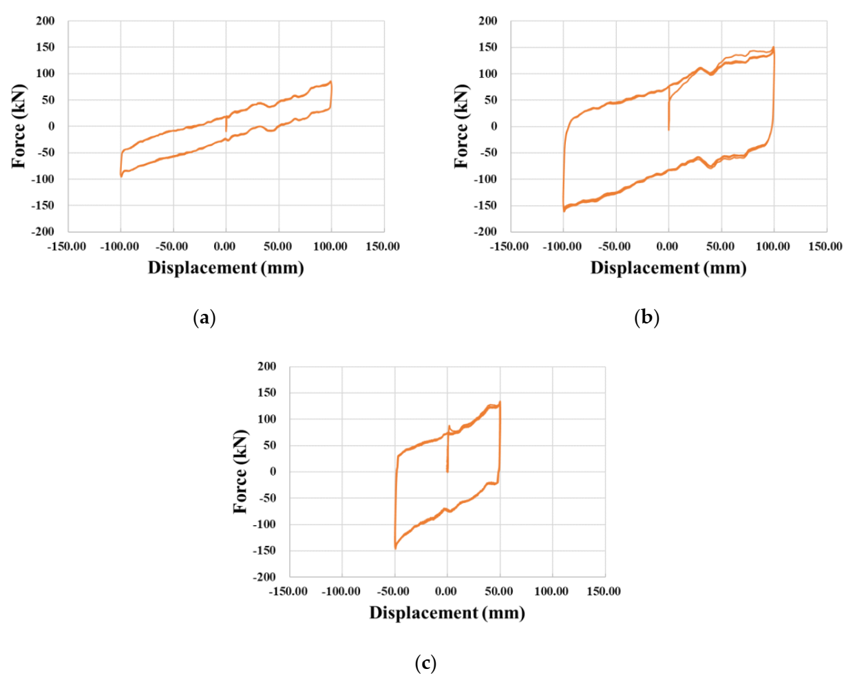
3.2. Compressive-Shear Test Results
As stated in the test guideline for bridge isolators, all the specimens were horizontally loaded three times within a range of design displacement. The shear force–displacement curves measured for the specimens are plotted in Figure 9. The compressive-shear test results are provided in Table 4 and can be compared with the design properties listed in Table 1 and Table 2. It appears that the shear stiffness of NRB and LRB can satisfy the design limit (90% of design shear stiffness). The shear stiffness of NRB was 25.9% higher than the design shear stiffness of 0.768 kN/mm. Even if the average shear stiffness of LRB fell below the design value, the design criterion was satisfied according to the guideline. On the contrary, the shear stiffness of EQS reached 85.1% of the design value and did not satisfy the design criterion. In view of EDC, LRB showed 33.119 kN·mm—that is, 130% of the design EDC—while EDC of EQS was 16.303 kN·mm—that is, 86% of the design value. Consequently, the considered commercial EQS failed to satisfy the test guideline for the bridge isolator despite its advantages in terms of size and maintenance. Here, this latter observation also stresses the necessity to apply strict quality management on the commercial seismic isolators.
4. Conclusions
A series of compressive tests and compressive-shear tests were conducted on NRB, LRB, and EQS specimens to examine the response characteristics of representative seismic isolation systems. The following conclusions are drawn:
- NRB showed relatively more consistent test results than LRB and EQS. LRB, which has improved energy dissipation capacity compared with NRB, exhibited lower performance than the design compressive stiffness. Though LRB and EQS have performance superior to that of NRB in terms of energy absorption capacity, only NRB satisfied the design criteria. It is, therefore, primordial to examine the quality of the isolators before their application to the structures.
- EQS is a novel seismic isolator with improved features. It is known that EQS can resist relatively larger vertical load than other kinds of isolators, and that it can be easily fixed after an earthquake. However, permanent deformation occurred when the design vertical load was applied in the test. Such unexpected deformation of the isolator can affect the friction between the components of EQS. Although EQS showed relatively high shear stiffness, the test results of EDC did not satisfy the target value in accordance with the test guideline for the bridge isolator. Therefore, it can be concluded that strict quality management on the commercial seismic isolators should be implemented.
- During the lifetime of the isolators, ageing and air temperature are important factors that affect the degradation of the rubber and friction coefficient of the sliding surface, respectively [23]. Therefore, further research will be conducted with considerations of durability.
Author Contributions
Conceptualization, C.B.C., Y.J.K., W.J.C., and J.-Y.L.; investigation, C.B.C., Y.J.K., and W.J.C.; writing—original draft preparation, C.B.C and J.-Y.L. All authors have read and agreed to the published version of the manuscript.
Funding
This research was supported by a grant from the Korea Institute of Civil Engineering and Building Technology (KICT), Korea (Project No. 2020–0038) and funded by the National Research Foundation of Korea NRF-2020R1F1A1050623.
Conflicts of Interest
The authors declare no conflict of interest.
References
- Tetratec Dynamic Isolation Systems. Available online: http://www.teratec.ca (accessed on 4 November 2020).
- Gil, H.; Han, K.; Gong, J.; Cho, D. Improvement of the performance-based seismic design method of cable supported bridges with the resilient-friction base isolation systems. Appl. Sci. 2020, 10, 3942. [Google Scholar] [CrossRef]
- Guéraud, R.; Noel-Leroux, J.-P.; Livolant, M.; Michalopoulos, A. Seismic isolation using sliding-elastomer bearing pads. Nucl. Eng. Des. 1985, 84, 363–377. [Google Scholar] [CrossRef]
- Annual Report 2018: Development of Safety Improvement Technolgy for Bridge Weak Connection and Seismic Equipment to Secure Evacuation and Recovery Route in Eqrthquake; Korea Institute of Civil Engineering and Building Technology: Goyang-si, Korea, 2018.
- Constantinou, M.C.; Tsopelas, P.; Kim, Y.; Okamoto, S. NCEER-Taisei Corporation Research Program on Sliding Seismic Isolation Systems for Bridges: Experimental and Analytical Study of a Friction Pendulum System (FPS); National Center for Earthquake Engineering Research Buffalo: Buffalo, NY, USA, 1993. [Google Scholar]
- Kim, B.-S.; Song, J.-K. Seismic responses of seismically isolated nuclear power plant structure considering post-yield stiffness of EQS bearing. EESK J. Earthq. Eng. 2016, 20, 319–329. [Google Scholar] [CrossRef]
- Lee, H.-P.; Cho, M.-S.; Kim, K.-K.; Maeng, S.-W. Development of Friction Type EQS for APR1400 Nuclear Power Plant. In Proceedings of Structural Mechanics in Reactor Technology, Manchester, UK, 10–14 August 2015; IASMiRT: Raleigh, NC, USA, 2015. [Google Scholar]
- Tsopelas, P.; Constantinou, M.C. NCEER-Taisei Corporation Research Program on Sliding Seismic Isolation Systems for Bridges: Experimental and Analytical Study of a System Consisting of Sliding Bearings and Fluid Restoring Force/Damping Devices; National Center for Earthquake Engineering Research Buffalo: Buffalo, NY, USA, 1994. [Google Scholar]
- Ealangi, I. Earthquake protection of buildings by seismic isolation devices and concepts. In Proceedings of the Young Researchers Conference, Mumbai, India, 15–16 January 2010. [Google Scholar]
- Naeim, F.; Kelly, J.M. Design of Isolated Structures from Theory to Practice; John Wiley & Sons Inc.: Hoboken, NJ, USA, 1999. [Google Scholar]
- Calvi, G.; Kawashima, K.; Billings, I.; Elnashai, A.; Nuti, C.; Pecker, A.; Pinto, P.; Priestley, M.; Rodriquez, M. Chapter 6: Design for enhanced control of damage. In FIB Bulletin 39: Seismic Bridge Desing and Retrofit—Structural Solutions; Fédération Internationale du Béton: Lausanne, Switzerland, 2007. [Google Scholar]
- Ramallo, J.; Johnson, E.; Spencer, B., Jr. “Smart” base isolation systems. J. Eng. Mech. 2002, 128, 1088–1099. [Google Scholar] [CrossRef] [Green Version]
- Tsopelas, P.; Constantinou, M.C. Study of elastoplastic bridge seismic isolation system. J. Struct. Eng. 1997, 123, 489–498. [Google Scholar] [CrossRef]
- Wu, T.-C. Design of Base Isolation System for Buildings. Master’s Thesis, Massachusetts Institute of Technology, Cambridge, MA, USA, June 2001. [Google Scholar]
- Chen, P.-C.; Tsai, K.-C.; Lin, P.-Y. Real-time hybrid testing of a smart base isolation system. Earthq. Eng. Struct. Dyn. 2014, 43, 139–158. [Google Scholar] [CrossRef]
- Chung, W.-J.; Yun, C.-B.; Kim, N.-S.; Seo, J.-W. Shaking table and pseudodynamic tests for the evaluation of the seismic performance of base-isolated structures. Eng. Struct. 1999, 21, 365–379. [Google Scholar] [CrossRef]
- Fenz, D.M.; Constantinou, M.C. Behaviour of the double concave Friction Pendulum bearing. Earthq. Eng. Struct. Dyn. 2006, 35, 1403–1424. [Google Scholar] [CrossRef]
- Lee, H.; Cho, M.; Moon, Y.; Han, W.; Ji, Y. A Study on Isolation Performance of Eradi Quake System Using Shaking Table Test and Analysis. In Proceedings of Structural Mechanics in Reactor Technology, Busan, Korea, 20–25 August 2017; IASMiRT: Raleigh, NC, USA, 2017. [Google Scholar]
- Tsopelas, P.; Constantinou, M.; Kim, Y.; Okamoto, S. Experimental study of FPS system in bridge seismic isolation. Earthq. Eng. Struct. Dyn. 1996, 25, 65–78. [Google Scholar] [CrossRef]
- Wang, Y.P.; Chung, L.L.; Liao, W.H. Seismic response analysis of bridges isolated with friction pendulum bearings. Earthq. Eng. Struct. Dyn. 1998, 27, 1069–1093. [Google Scholar] [CrossRef]
- Yu, S.-M.; Lee, Y.-I.; Ji, Y.-S.; Choi, D.-S.; Kim, D.-K. A study on the application of EQS bearings for the seismic isolation of building structures by ICT case study. EESK J. Earthq. Eng. 2013, 17, 61–70. [Google Scholar]
- Korea Institute of Civil Engineering and Building Technology. Test Guidelines for Bridge Isolators; KICT: Goyang-si, Korea, 2019. [Google Scholar]
- Mazza, F. Effects of the long-term behaviour of isolation devices on the seismic response of base-isolated buildings. Struct. Control Health Monit. 2019, 26, e2331. [Google Scholar] [CrossRef]
Figure 1.
Elastomeric bearings: (a) Natural Rubber Bearing (NRB); (b) Lead Rubber Bearing (LRB).

Figure 2.
Composition of Eradi-Quake System (EQS).

Figure 3.
Compressive test setup: (a) photograph of compressive test machine; (b) conceptual drawing of compressive test; (c) installed Linear Variable Displacement Transducer (LVDT) for LRB and NRB; (d) installed LVDT for EQS.
Figure 3.
Compressive test setup: (a) photograph of compressive test machine; (b) conceptual drawing of compressive test; (c) installed Linear Variable Displacement Transducer (LVDT) for LRB and NRB; (d) installed LVDT for EQS.

Figure 4.
Details of biaxial loading adopted in compressive test of seismic isolators.

Figure 5.
Conceptual drawing of compressive-shear test setup.

Figure 6.
Lateral (shear) loading history: (a) NRB and LRB; (b) EQS.

Figure 7.
Shear behavior of isolators: (a) NRB; (b) LRB and EQS.

Figure 8.
Measured compressive force–displacement curves: (a) NRB; (b) LRB; (c) EQS.

Figure 9.
Measured shear force–displacement curves: (a) NRB; (b) LRB; (c) EQS.


Table 1.
Design properties of NRB and LRB specimens.
| Isolator | d (mm) | Pv (kN) | G (MPa) | Kv (kN/mm) | Kh (kN/mm) | Py (kN) | EDC (kN·mm) | Pb (kN) |
|---|---|---|---|---|---|---|---|---|
| LRB | 500 | 2945 | 0.392 | 2.057 | 1.414 | 67.5 | 25.118 | 12,824 |
| NRB | 500 | 2945 | 0.392 | 1.865 | 0.768 | - | - | 10,766 |
Table 2.
Design properties of EQS specimens.
| Isolator | Ldead (kN) | Llive (kN) | L (kN) | Pv (kN) | dmax (mm) | fmax | fmim | Keff (kN/mm) | EDC (kN·mm) |
|---|---|---|---|---|---|---|---|---|---|
| EQS | 1350 | 500 | 1850 | 2775 | ±50 | 0.138 | 0.055 | 3.219 | 18.900 |
Table 3.
Details of biaxial loading adopted in compressive test by type of seismic isolators.
| Isolator | Diameter, d (mm) | Design Vertical Load, p0 (kN) | p1 = 70% × p0 (kN) | p2 = 130% × p0 (kN) |
|---|---|---|---|---|
| LRB | 500 | 2000 | 1400 | 2600 |
| NRB | 500 | 2000 | 1400 | 2600 |
| EQS | 305 | 1850 | 1295 | 2405 |
Table 4.
Compressive test results of NRB, LRB, and EQS specimens.
| Isolator | Compressive Stiffness, Kv (kN/mm) | Shear Stiffness, Kh (kN/mm) | EDC (kN·mm) | Equivalent Damping, heq | |
|---|---|---|---|---|---|
| NRB | Specimen #1 | 1236 | 0.9423 | - | - |
| Specimen #2 | 1248 | 0.9975 | - | - | |
| Specimen #3 | 1193 | 0.9611 | - | - | |
| Average | 1226 | 0.9670 | - | - | |
| LRB | Specimen #1 | 1347 | 1.3008 | 32,574 | 0.3995 |
| Specimen #2 | 1418 | 1.3139 | 32,536 | 0.3951 | |
| Specimen #3 | 1361 | 1.3069 | 34,247 | 0.4181 | |
| Average | 1375 | 1.3072 | 33,119 | 0.4042 | |
| EQS | Specimen #1 | 1370 | 2.7400 | 16,303 | 0.3788 |
Publisher’s Note: MDPI stays neutral with regard to jurisdictional claims in published maps and institutional affiliations. |
© 2020 by the authors. Licensee MDPI, Basel, Switzerland. This article is an open access article distributed under the terms and conditions of the Creative Commons Attribution (CC BY) license (http://creativecommons.org/licenses/by/4.0/).
Share and Cite
MDPI and ACS Style
Cho, C.B.; Kim, Y.J.; Chin, W.J.; Lee, J.-Y. Comparing Rubber Bearings and Eradi-Quake System for Seismic Isolation of Bridges. Materials 2020, 13, 5247. https://0-doi-org.brum.beds.ac.uk/10.3390/ma13225247
AMA Style
Cho CB, Kim YJ, Chin WJ, Lee J-Y. Comparing Rubber Bearings and Eradi-Quake System for Seismic Isolation of Bridges. Materials. 2020; 13(22):5247. https://0-doi-org.brum.beds.ac.uk/10.3390/ma13225247
Chicago/Turabian StyleCho, Chang Beck, Young Jin Kim, Won Jong Chin, and Jin-Young Lee. 2020. "Comparing Rubber Bearings and Eradi-Quake System for Seismic Isolation of Bridges" Materials 13, no. 22: 5247. https://0-doi-org.brum.beds.ac.uk/10.3390/ma13225247
Note that from the first issue of 2016, this journal uses article numbers instead of page numbers. See further details here.