
Influence of Silica-Aerogel on Mechanical Characteristics of Polyurethane-Based Composites: Thermal Conductivity and Strength

Abstract
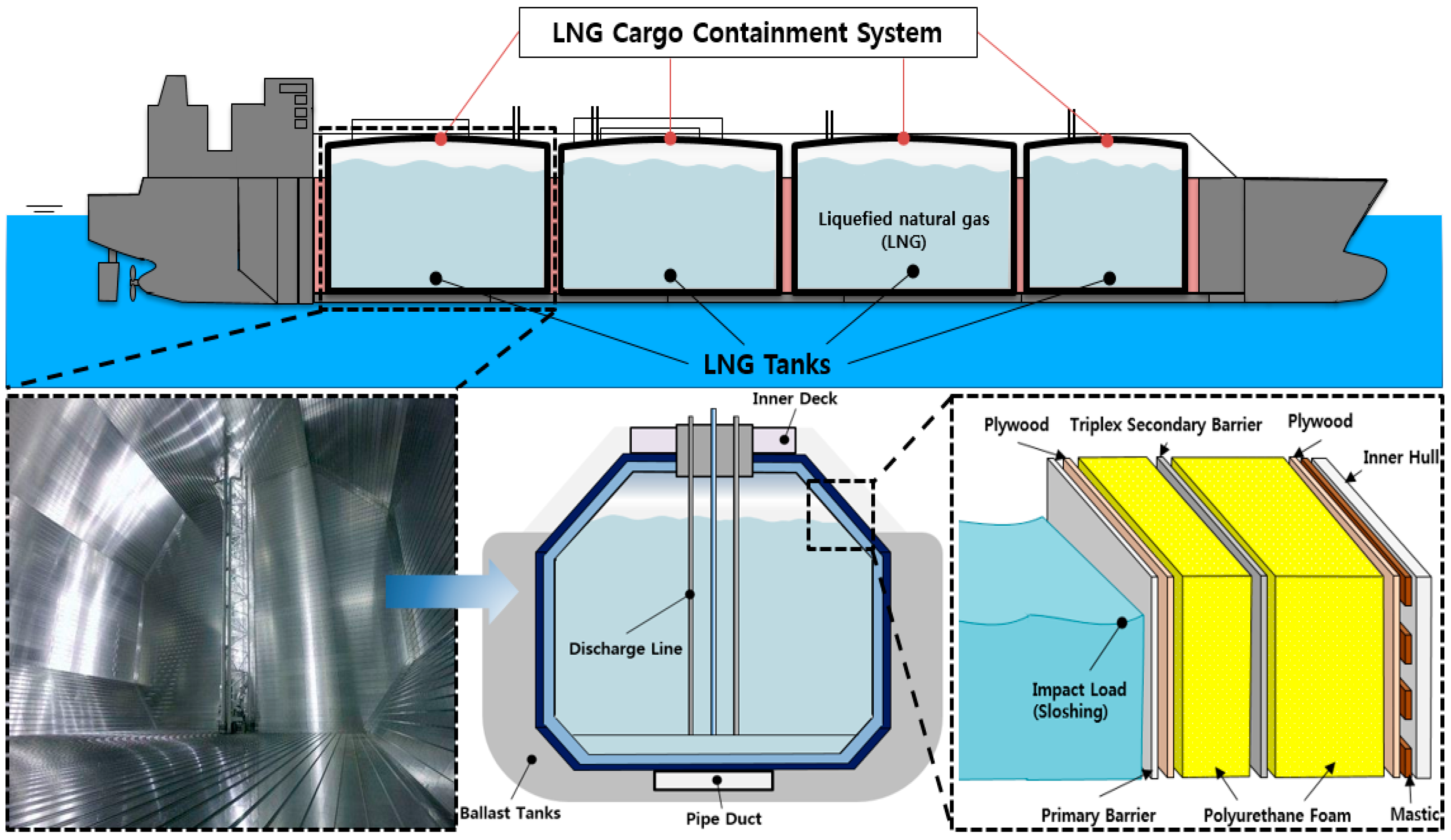
:1. Introduction
2. Experimental Preparations
2.1. Experimental Scenario
2.2. Raw Materials
2.3. Preparation of PUF-Silica Aerogel Composites
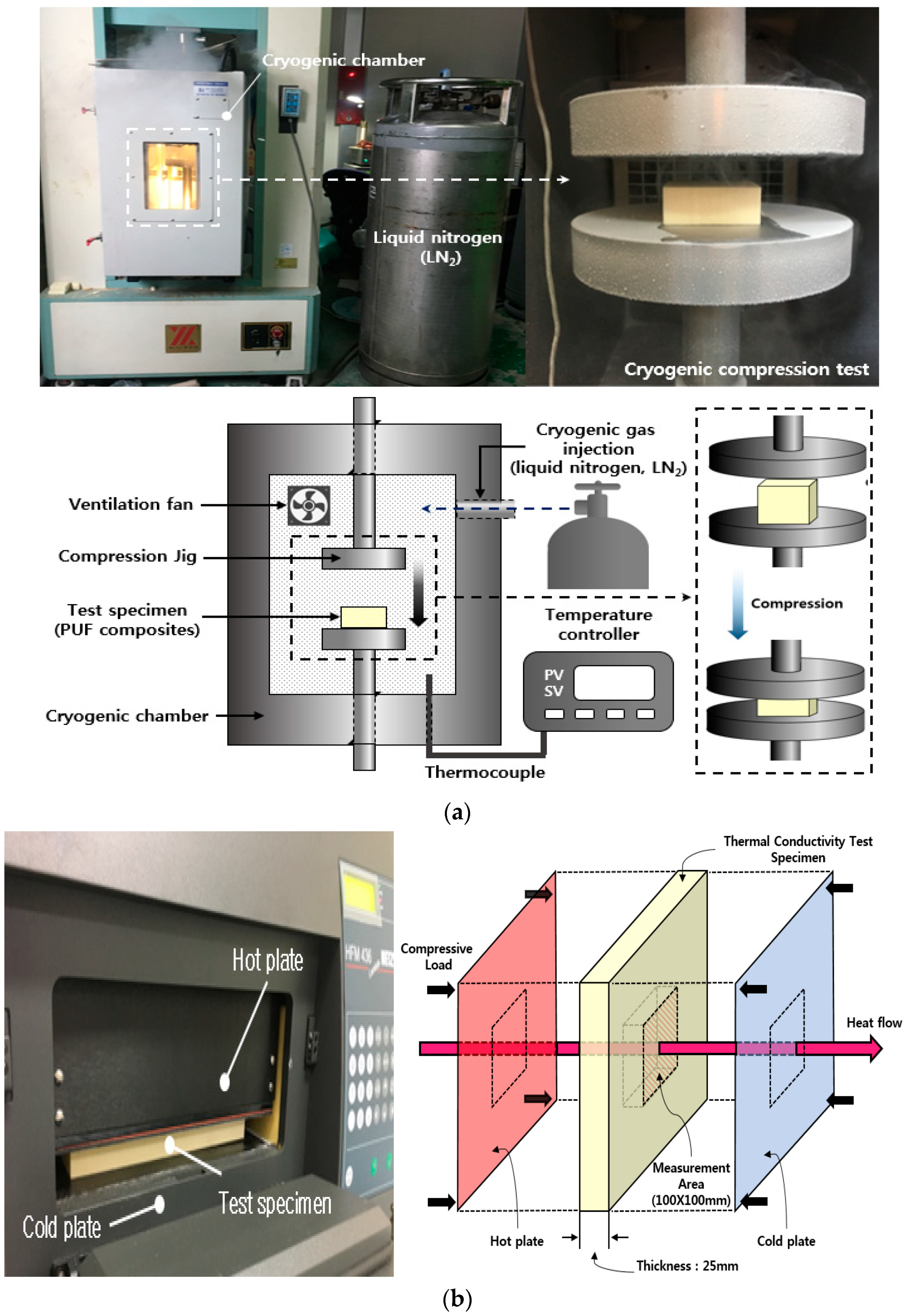
2.4. Experimental Apparatus
3. Results and Discussion
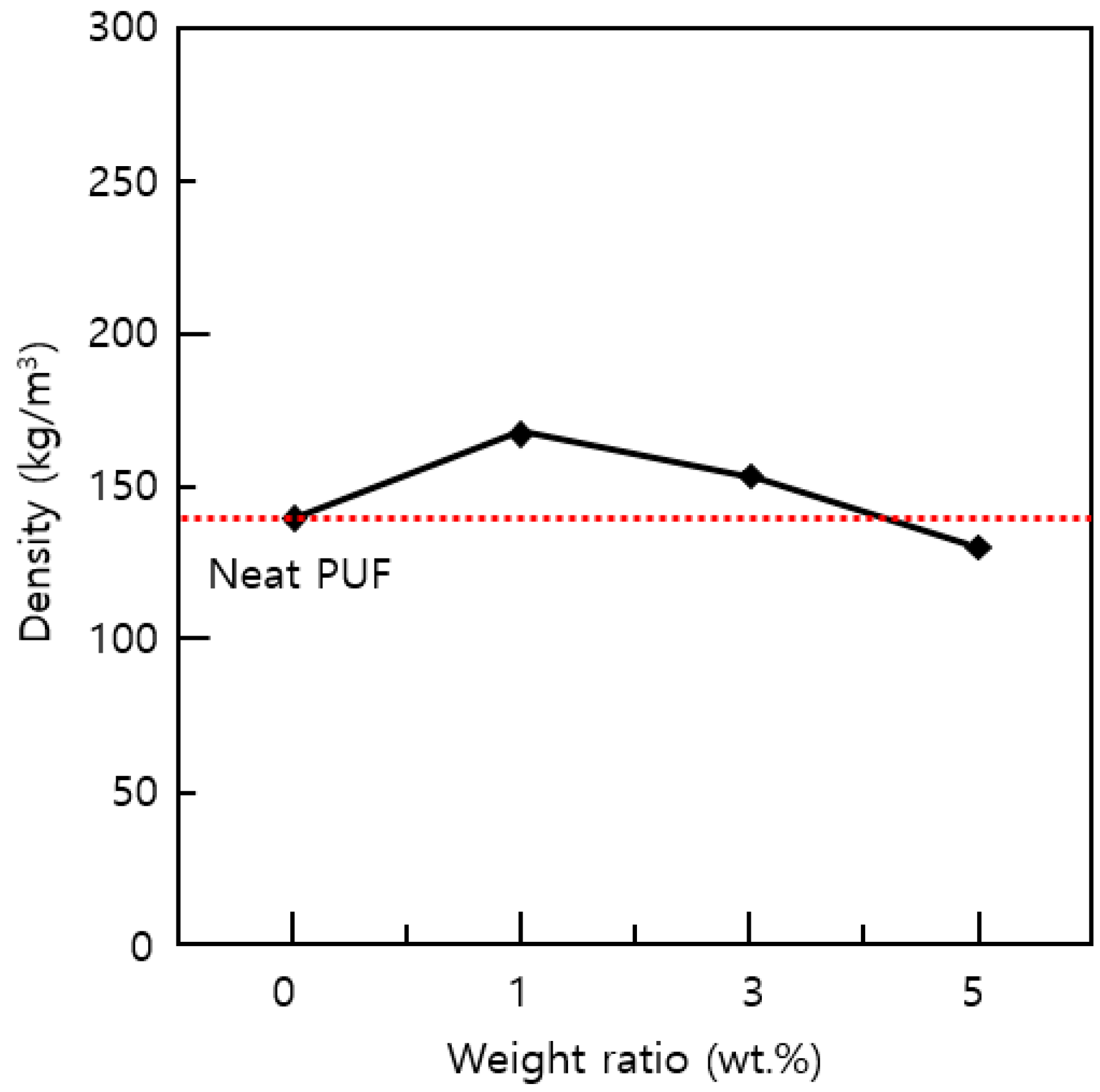
3.1. Density of PUF-Silica Aerogel Composites
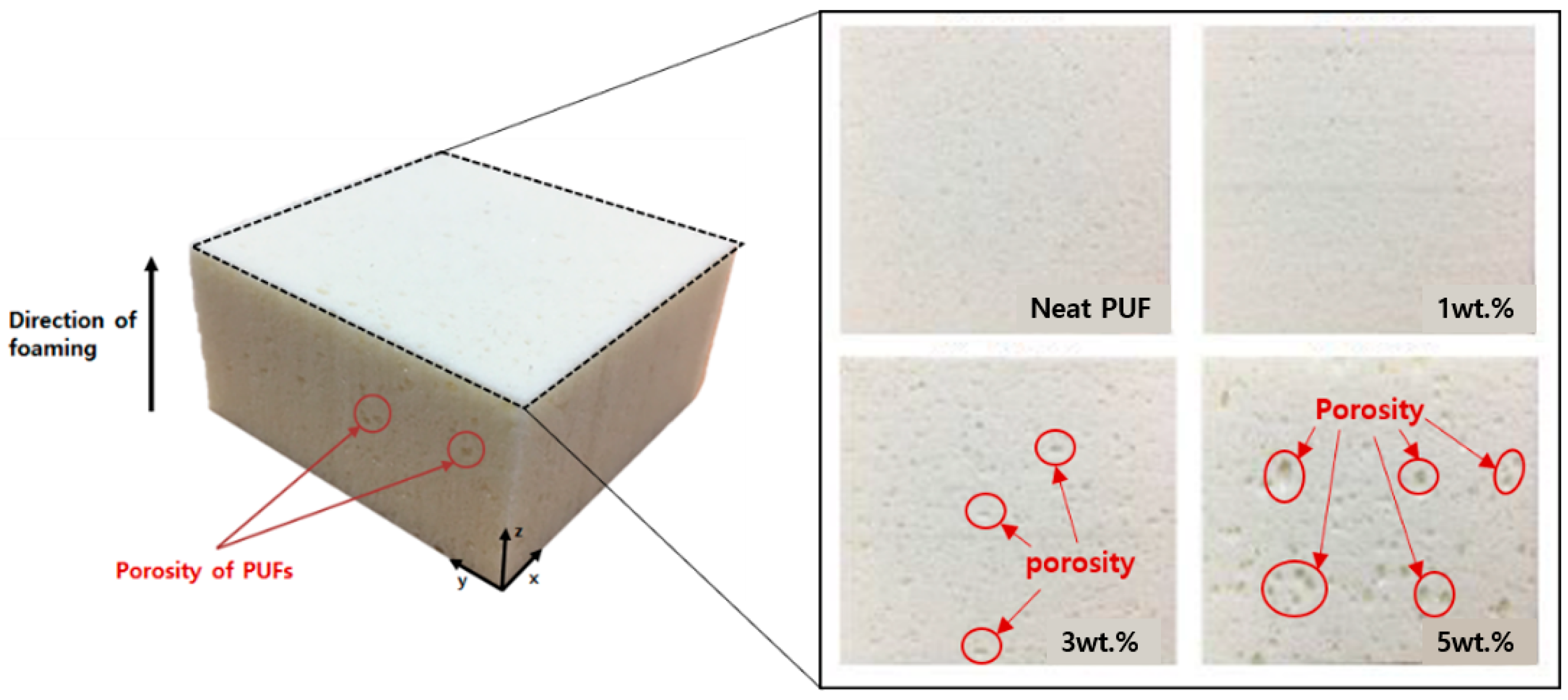
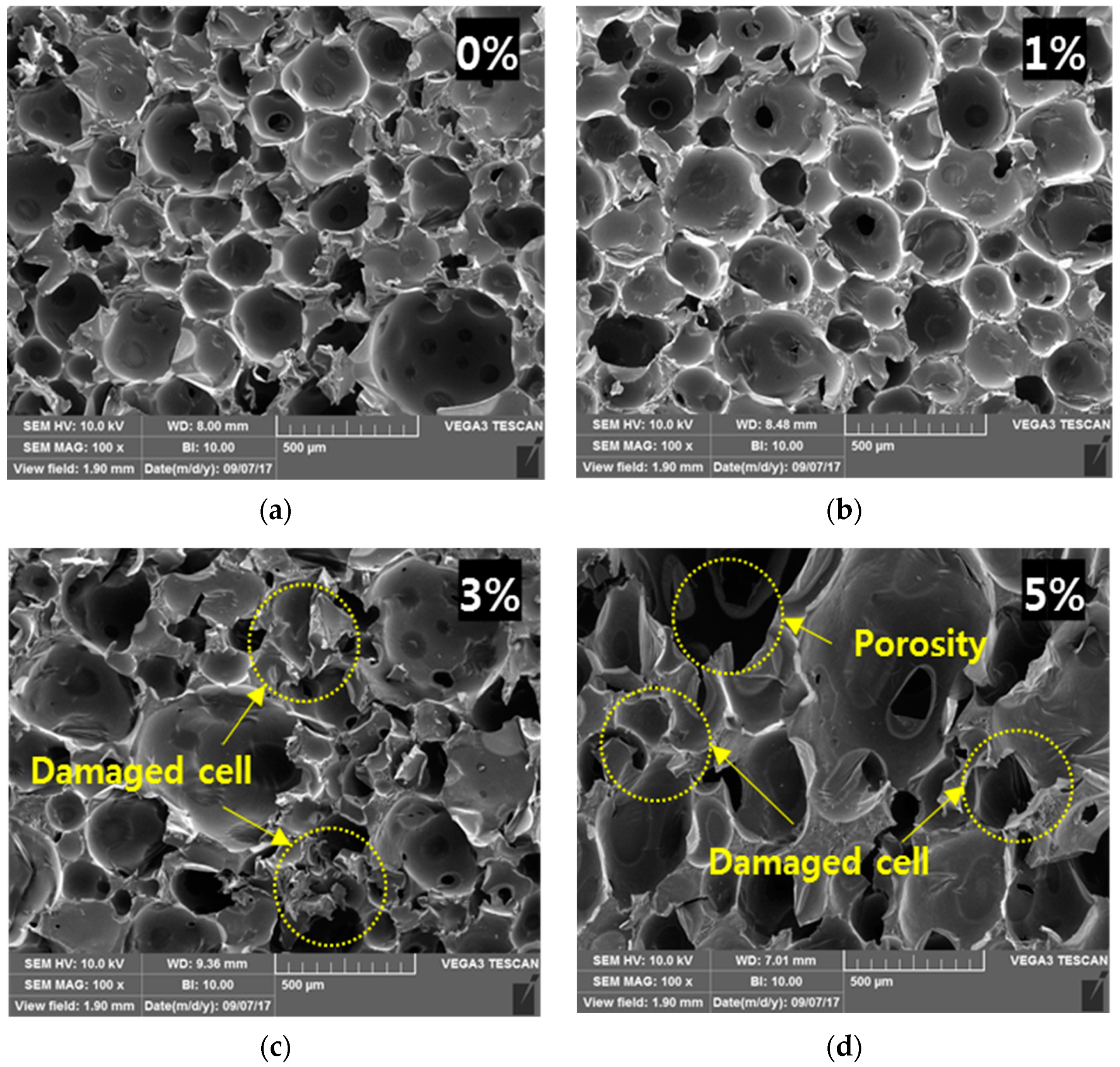
3.2. Morphological Characteristics
3.3. Thermal Conductivity
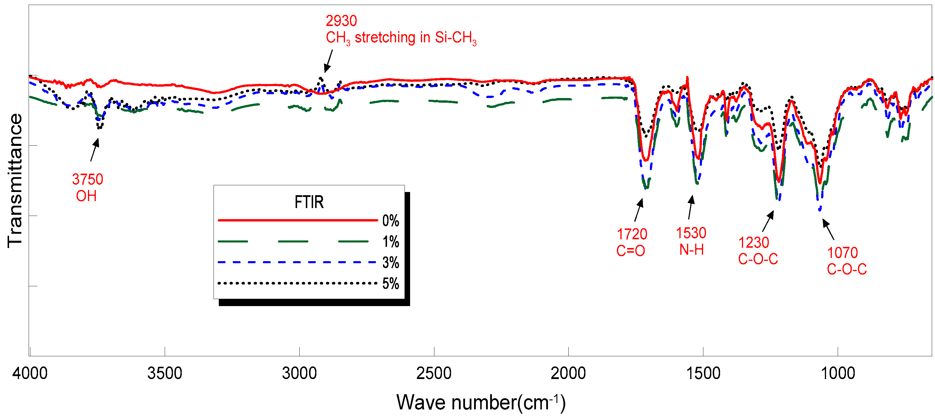
3.4. The Fourier Transform Infrared (FTIR) Analysis
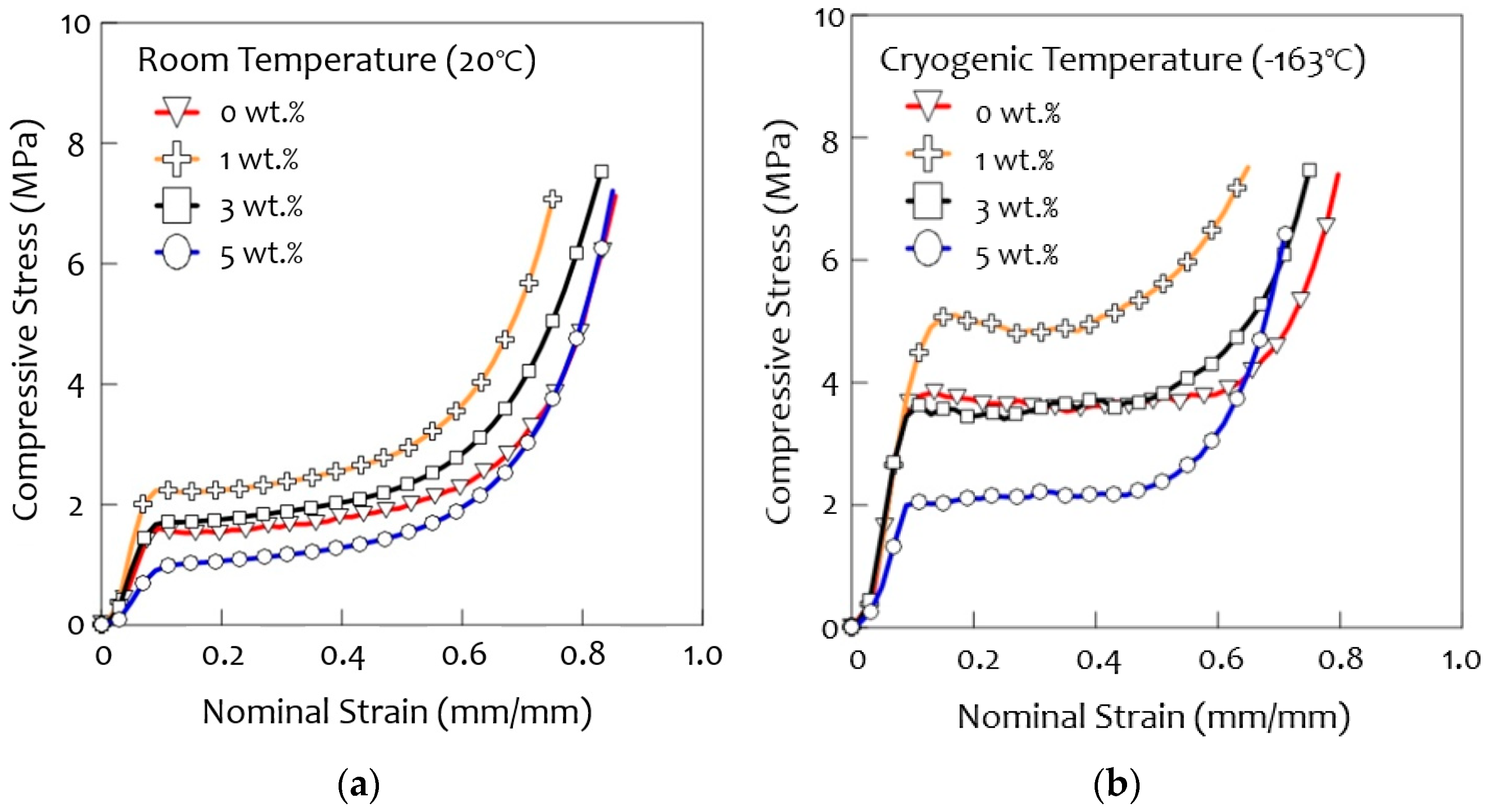
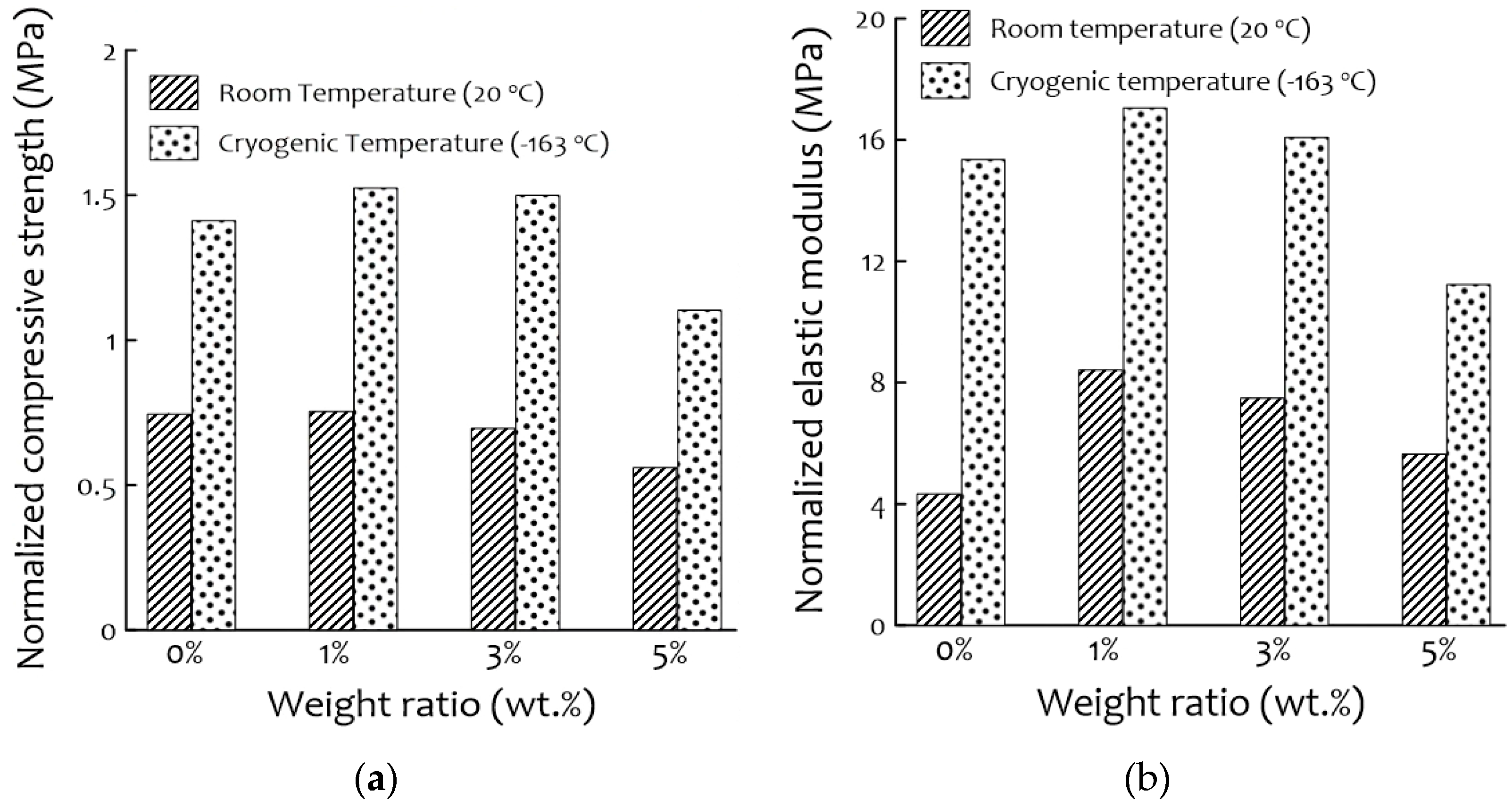
3.5. Compression Tests
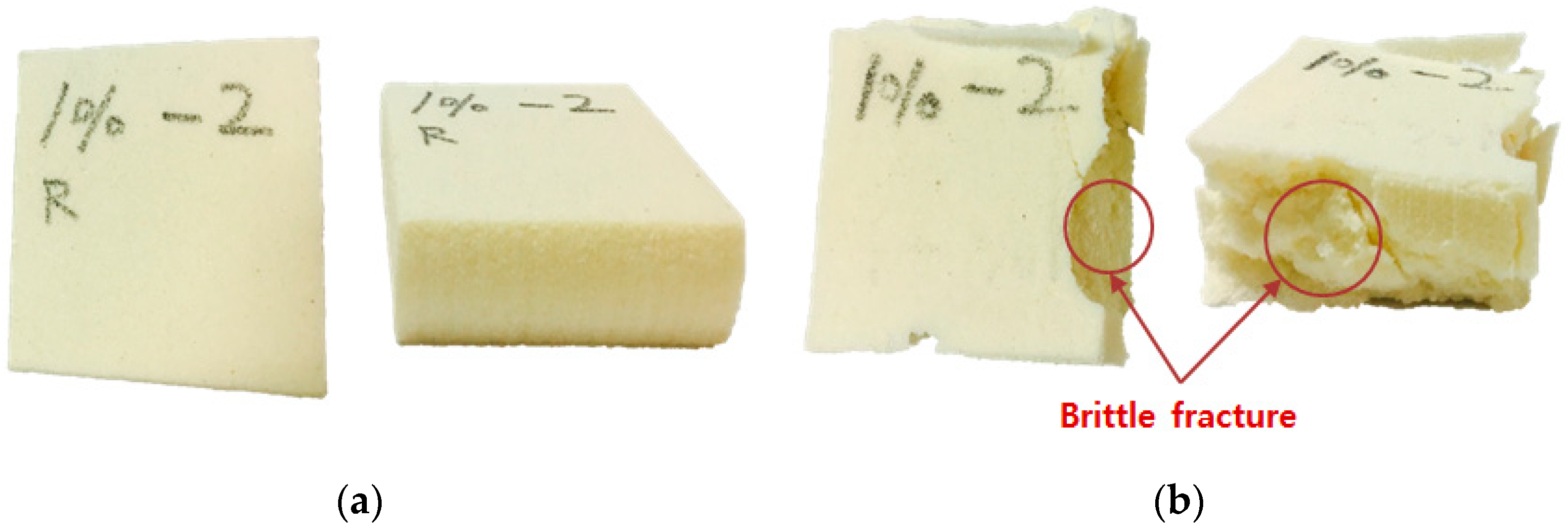
3.6. Fracture Characterization
4. Conclusions
- ∙
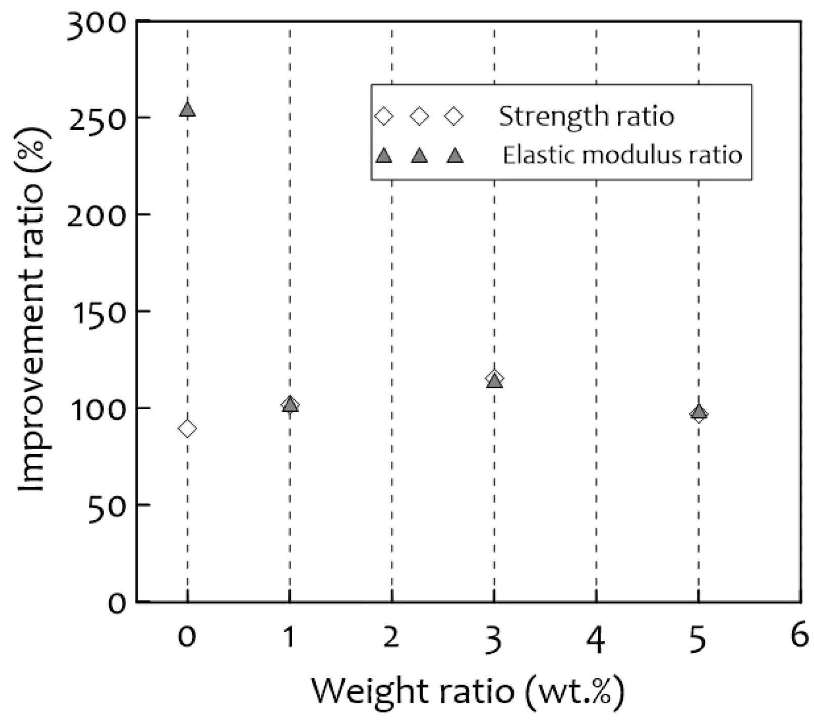
- The optimal content of silica aerogel in this research was 1 wt.%, which led to a significant increase in compressive strength both at room temperature (20 °C) and cryogenic temperature (−163 °C).
- ∙
- The cell morphology of PUF-silica aerogel composites was relatively homogeneous, and the cell shape remained closed at 1 wt.% in comparison with the other concentrations.
- ∙
- The specific thermal conductivity of the 1 wt.% PUF-silica aerogel composites was lower because of the uniform and homogenous cell shape modification of the cellular structure and the extremely low thermal conductivity of the silica aerogel material, despite the increasing density, which had a significant effect on the insulation performance.
- ∙
- The mechanical properties were reduced by increasing the silica aerogel content to 3 wt.% and 5 wt.%, mainly because of the pores generated on the surface of the composites. Because of the generated pores and nonhomogeneous cell distribution with silica aerogel dispersion in the PUF, the thermal insulation properties also decreased.
Author Contributions
Funding
Institutional Review Board Statement
Informed Consent Statement
Data Availability Statement
Conflicts of Interest
References
- Oberthür, S. Institutional interaction to address greenhouse gas emissions from international transport: ICAO, IMO and the Kyoto Protocol. Clim. Policy 2003, 3, 191–205. [Google Scholar] [CrossRef]
- Desai, S.; Thakore, I.M.; Sarawade, B.D.; Devi, S. Effect of polyols and diisocyanates on thermo-mechanical and morpholog-ical properties of polyurethanes. Eur. Polym. J. 2000, 36, 711–725. [Google Scholar] [CrossRef]
- Park, S.B.; Lee, C.S.; Choi, S.W.; Kim, J.H.; Bang, C.S.; Lee, J.M. Polymeric foams for cryogenic temperature application: Temperature range for non-recovery and brittle-fracture of microstructure. Compos. Struct. 2016, 136, 258–269. [Google Scholar] [CrossRef]
- Han, D.S.; Park, I.B.; Kim, M.H.; Noh, B.J.; Kim, W.S.; Lee, J.M. The Effects of Glass Fiber Reinforcement on the Mechanical Behavior of Polyurethane Foam. J. Mech. Sci. Technol. 2010, 24, 263–266. [Google Scholar] [CrossRef]
- Lee, J.H.; Park, S.B.; Kim, S.K.; Bang, C.S.; Lee, J.M. Application of Gurson Model for Evaluation of Density-Dependent Me-chanical Behavior of Polyurethane Foam: Comparative Study on Explicit and Implicit Method. Macromol. Mater. Eng. 2016, 301, 694–706. [Google Scholar] [CrossRef]
- Park, S.B.; Choi, S.W.; Kim, J.H.; Bang, C.S.; Lee, J.M. Effect of the blowing agent on the low-temperature mechanical prop-erties of CO2-and HFC-245fa-blown glass-fiber-reinforced polyurethane foams. Compos. Part B 2016, 93, 317–327. [Google Scholar] [CrossRef]
- Lee, C.S.; Lee, J.M. Failure analysis of reinforced polyurethane foam-based LNG insulation structure using damage-coupled finite element analysis. Compos. Struct. 2014, 107, 231–245. [Google Scholar] [CrossRef]
- Cai, D.; Jin, J.; Yusoh, K.; Rafiq, R.; Song, M. High performance polyurethane/functionalized graphene nanocomposites with improved mechanical and thermal properties. Compos. Sci. Technol. 2012, 72, 702–707. [Google Scholar] [CrossRef]
- Xie, T.; He, Y.L.; Hu, Z.J. Theoretical study on thermal conductivities of silica aerogel composite insulating material. Int. J. Heat Mass Transf. 2013, 58, 540–552. [Google Scholar] [CrossRef]
- Hong, S.K.; Yoon, M.Y.; Hwang, H.J. Synthesis of spherical silica aerogel powder by emulsion polymerization technique. J. Ceram Process. Res. 2012, 13, 145–148. [Google Scholar]
- Lei, Y.; Chen, X.; Song, H.; Hu, Z.; Cao, B. The influence of thermal treatment on the microstructure and thermal insulation performance of silica aerogels. J. Non-Cryst. Solids 2017, 470, 178–183. [Google Scholar] [CrossRef]
- Venkataraman, M.; Mishra, R.; Militky, J.; Hes, L. Aerogel based nanoporous fibrous materials for thermal insulation. Fiber. Polym. 2014, 15, 1444–1449. [Google Scholar] [CrossRef]
- Cimavilla-Roman, P.; Perez-Tamarit, S.; Santiago-Calvo, M.; Rodriguez-Perez, M.A. Influence of silica aerogel particles on the foaming process and cellular structure of rigid polyurethane foams. Eur. Polym. J. 2020, 135, 109884. [Google Scholar] [CrossRef]
- Bonab, S.A.; Moghaddas, J.; Rezaei, M. In-situ synthesis of silica aerogel/polyurethane inorgan-ic-organic hybrid nanocomposite foams: Characterization, cell microstructure and mechanical prop-erties. Polymer 2019, 172, 27–40. [Google Scholar] [CrossRef]
- Cho, J.; Jang, H.G.; Kim, S.Y.; Yang, B. Flexible and coatable insulating silica aerogel/polyurethane composites via soft segment control. Compos. Sci. Technol. 2019, 171, 244–251. [Google Scholar] [CrossRef]
- KS M ISO 844. Rigid Cellular Plastics-Determination of Compression Properties; Korean Industrial Standards: Seoul, Korean, 2012. [Google Scholar]
- Yoo, J.K. Technical Data Sheet: Silica Aerogel Powder Type; Remtech.Co., Ltd.: Daejon, Korea, 2014. [Google Scholar]
- ASTM C518. Standard Test Method for Steady-State Thermal Transmission Properties by Means of the Heat Flow Meter Apparatus; ASTM International: West Conshohocken, PA, USA, 2017. [Google Scholar]
- Saha, M.C.; Mahfuz, H.; Chakravarty, U.K.; Uddin, M.; Kabir, M.E.; Jeelani, S. Effect of density, microstructure, and strain rate on compression behavior of polymeric foams. Mater. Sci. Eng. A 2005, 406, 328–336. [Google Scholar] [CrossRef]
- Saint-Michel, F.; Chazeau, L.; Cavaille, J.Y.; Charbert, E. Mechanical properties of high density polyurethane foams: I. Effect of the density. Compos. Sci. Technol. 2006, 66, 2700–2708. [Google Scholar] [CrossRef]
- Nazeran, N.; Moghaddas, J. Synthesis and characterization of silica aerogel reinforced rigid polyurethane foam for thermal insulation application. J. Non-Cryst. Solids 2017, 461, 1–11. [Google Scholar] [CrossRef]
- Hawkins, M.C.; O’Toole, B.; Jackovich, D. Cell Morphology and Mechanical Properties of Rigid Polyurethane Foam. J. Cell. Plast. 2005, 41, 267–285. [Google Scholar] [CrossRef]
- Gibson, L.J.; Ashby, M.F. Cellular Solids: Structure and Properties; Pergamon Press: Oxford, UK, 1997; pp. 283–307. [Google Scholar]
- Kim, S.H.; Park, H.C.; Jeong, H.M.; Kim, B.K. Glass fiber reinforced rigid polyurethane foams. J. Mater. Sci. 2010, 45, 2675–2680. [Google Scholar] [CrossRef]
- Kim, S.G.; Lim, H.; Song, J.C.; Kim, B.K.; Devi, S. Effect of blowing agent type in rigid polyurethane foam. J. Macromol. Sci. Part A Pure Appl. Chem. 2008, 45, 323–327. [Google Scholar] [CrossRef]
- Jung, H.C.; Ryu, S.C.; Kim, W.N.; Lee, Y.B.; Choe, K.H.; Kim, S.B. Properties of rigid polyurethane foams blown by HCFC 141B and distilled water. J. Appl. Polym. Sci. 2001, 81, 486–493. [Google Scholar] [CrossRef]
- Santiago-Calvo, M.; Blasco, V.; Ruiz, C.; Paris, R.; Villafane, F. Synthesis, characterization and physical properties of rigid polyurethane foams prepared with poly (propylene oxide) polyols containing graphene oxide. Eur. Polym. J. 2017, 97, 230–240. [Google Scholar] [CrossRef]
- Wang, Y.; Wu, J.; Xue, Z.; Liu, Z. Thermal Conductivity of HFC-245fa from (243 to 413) K. J. Chem. Eng. Data 2006, 51, 1424–1428. [Google Scholar] [CrossRef]
- Klett, J.; Hardy, R.; Romine, E.; Walls, C.; Burchell, T. High-thermal-conductivity, mesophase-pitch-derived carbon foams: Effect of precursor on structure and properties. Carbon 2000, 38, 953–973. [Google Scholar] [CrossRef]
- Grace, I.; Pilipchuk, V.; Ibrahim, R.; Ayorinde, E. Temperature effect on non-stationary compressive loading response of polymethacrylimide solid foam. Compos. Struct. 2012, 94, 3052–3063. [Google Scholar] [CrossRef]
- Dorcheh, A.S.; Abbasi, M.H. Silica Aerogel; Synthesis, Properties and Characterization. J. Mater. Process. Technol. 2008, 199, 10–26. [Google Scholar] [CrossRef]


| Silica Aerogel | Contents |
|---|---|
| Particle size range | 10–200 μm |
| Void diameter | 20 nm |
| Pore volume | 2.2–2.5 cm3/g |
| Particle density | 70–150 kg/m3 |
| Thermal conductivity | 0.0018–0.02W/m·K at 25 °C |
| Surface area | 300–350 m2/g |
| Porosity | 90–99% |
| Materials | Content | ||
|---|---|---|---|
| Weight (g) | Ratio (%) | ||
| Polyol Mixture | 1000 | - | |
| Polymeric MDI | 1160 | - | |
| HFC-245fa | 50 | - | |
| Silica Aerogels | 0 wt.% Neat PUF | 0 | 0 |
| 1 wt.% PUF-silica aerogel composites | 22.1 | 1 | |
| 3 wt.% PUF-silica aerogel composites | 66.3 | 3 | |
| 5 wt.% PUF-silica aerogel composites | 110.5 | 5 | |
| Material | Thermal Conductivity | Standard Deviation |
|---|---|---|
| Neat PUF (0 wt%) | 0.03031 W/m∙K | 0.00003 W/m∙K |
| 1 wt.% PUF-silica aerogel | 0.03022 W/m∙K | 0.00003 W/m∙K |
| 3 wt.% PUF-silica aerogel | 0.03109 W/m∙K | 0.00010 W/m∙K |
| 5 wt.% PUF-silica aerogel | 0.03414 W/m∙K | 0.00014 W/m∙K |
Publisher’s Note: MDPI stays neutral with regard to jurisdictional claims in published maps and institutional affiliations. |
© 2021 by the authors. Licensee MDPI, Basel, Switzerland. This article is an open access article distributed under the terms and conditions of the Creative Commons Attribution (CC BY) license (https://creativecommons.org/licenses/by/4.0/).
Share and Cite
Kim, J.-H.; Ahn, J.-H.; Kim, J.-D.; Lee, D.-H.; Kim, S.-K.; Lee, J.-M. Influence of Silica-Aerogel on Mechanical Characteristics of Polyurethane-Based Composites: Thermal Conductivity and Strength. Materials 2021, 14, 1790. https://0-doi-org.brum.beds.ac.uk/10.3390/ma14071790
Kim J-H, Ahn J-H, Kim J-D, Lee D-H, Kim S-K, Lee J-M. Influence of Silica-Aerogel on Mechanical Characteristics of Polyurethane-Based Composites: Thermal Conductivity and Strength. Materials. 2021; 14(7):1790. https://0-doi-org.brum.beds.ac.uk/10.3390/ma14071790
Chicago/Turabian StyleKim, Jeong-Hyeon, Jae-Hyeok Ahn, Jeong-Dae Kim, Dong-Ha Lee, Seul-Kee Kim, and Jae-Myung Lee. 2021. "Influence of Silica-Aerogel on Mechanical Characteristics of Polyurethane-Based Composites: Thermal Conductivity and Strength" Materials 14, no. 7: 1790. https://0-doi-org.brum.beds.ac.uk/10.3390/ma14071790