
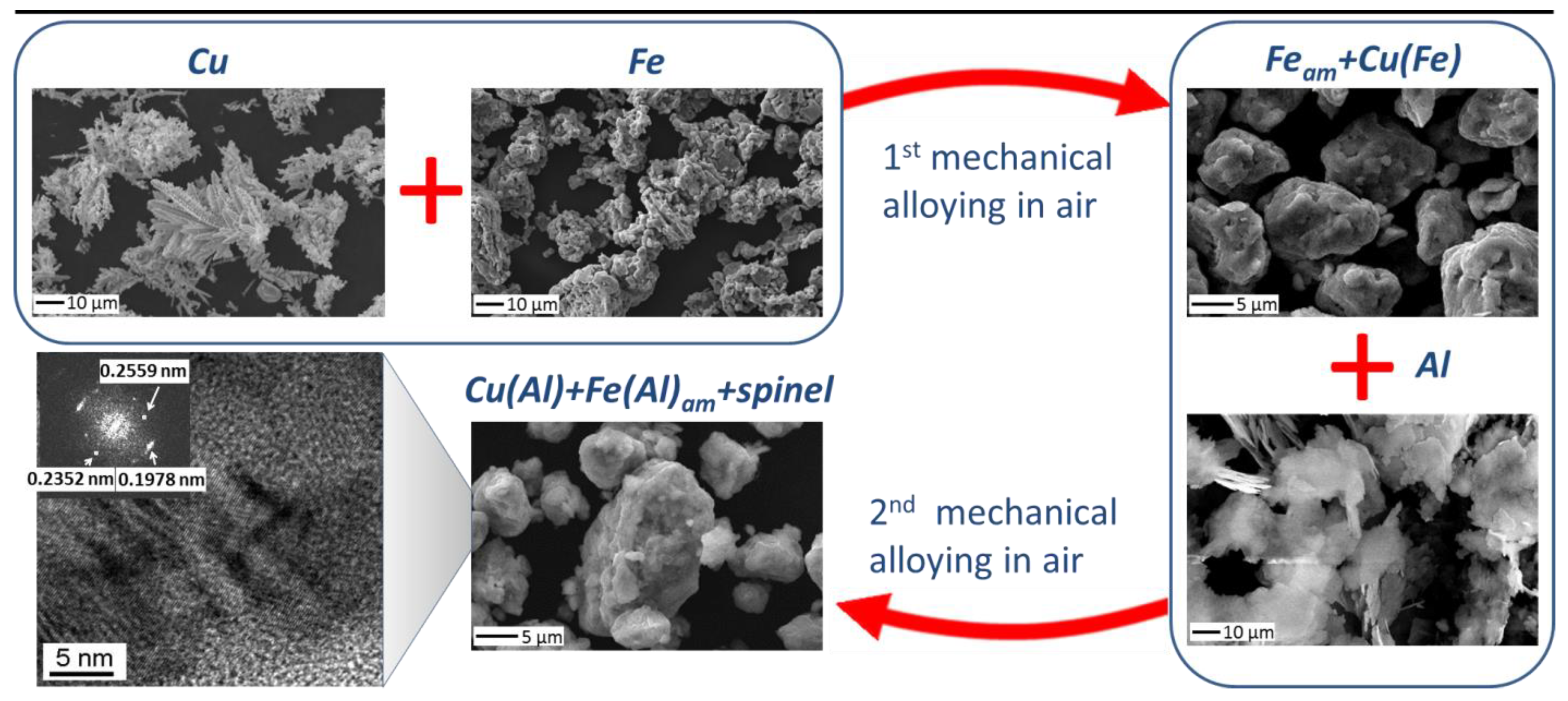
Elimination of Composition Segregation in 33Al–45Cu–22Fe (at.%) Powder by Two-Stage High-Energy Mechanical Alloying


 , , , and
Abstract
:1. Introduction
2. Materials and Methods
2.1. Materials
2.2. Mechanical Alloying
2.3. Methods
3. Results
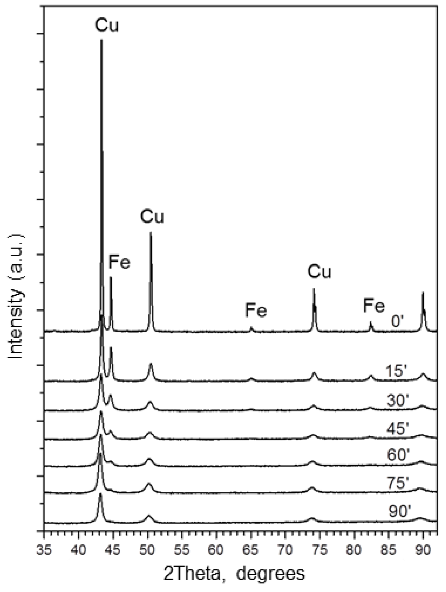
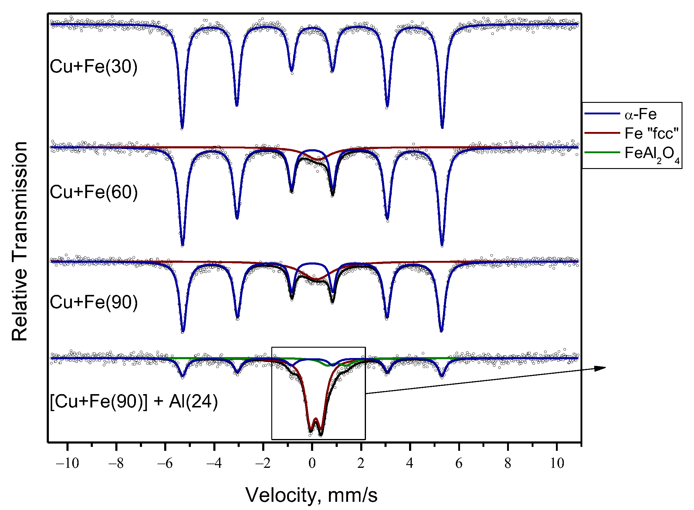
3.1. Mechanical Alloying of Cu and Fe
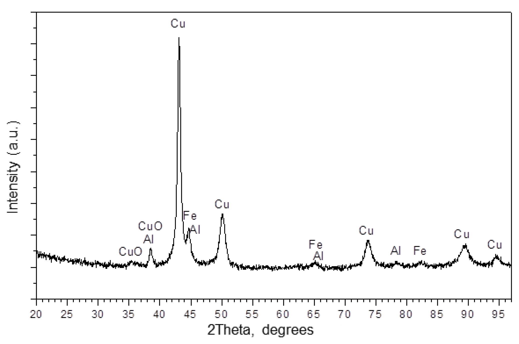
- The ICDD data the observed phases are given.
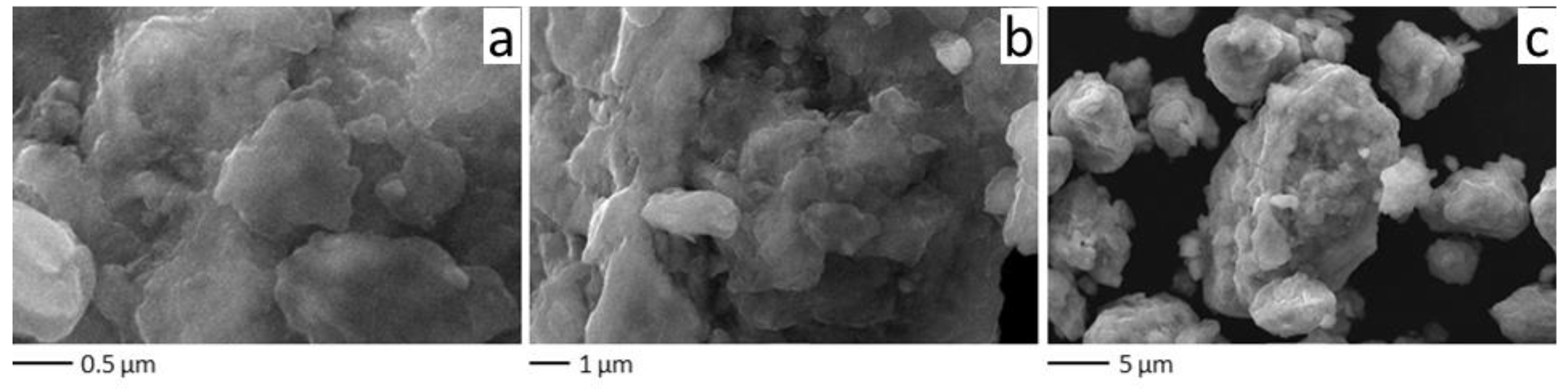
3.2. Mechanical Alloying of a Mixture of Ball-Milled (Cu+Fe) and Newly Added Al
4. Discussion
4.1. Phase Composition and Microstructure of the Mechanically Alloyed Cu+Fe Powder Mixture
4.2. Phase Composition and Microstructure of the Product of Two-Stage Mechanical Alloying of the (Cu+Fe) + Al Mixture
5. Conclusions
Author Contributions
Funding
Institutional Review Board Statement
Informed Consent Statement
Data Availability Statement
Acknowledgments
Conflicts of Interest
References
- Tikhov, S.F.; Minyukova, T.P.; Valeev, K.R.; Cherepanova, S.V.; Salanov, A.N.; Kaichev, V.V.; Saraev, A.A.; Andreev, A.S.; Lapina, O.B.; Sadykov, V.A. Design of Micro-Shell Cu–Al Porous Ceramometals as Catalysts for the Water–Gas Shift Reaction. RSC Adv. 2017, 7, 42443–42454. [Google Scholar] [CrossRef] [Green Version]
- Lin, X.; Zhang, Y.; Yin, L.; Chen, C.; Zhan, Y.; Li, D. Characterization and Catalytic Performance of Copper-Based WGS Catalysts Derived from Copper Ferrite. Int. J. Hydrog. Energy 2014, 39, 6424–6432. [Google Scholar] [CrossRef]
- Shechtman, D.; Blech, I.; Gratias, D.; Cahn, J.W. Metallic Phase with Long-Range Orientational Order and No Translational Symmetry. Phys. Rev. Lett. 1984, 53, 1951–1953. [Google Scholar] [CrossRef] [Green Version]
- Kelhar, L.; Ferčič, J.; Maček-Kržmanc, M.; Zavašnik, J.; Šturm, S.; Koželj, P.; Kobe, S.; Dubois, J.-M. The Role of Fe and Cu Additions on the Structural, Thermal and Magnetic Properties of Amorphous Al-Ce-Fe-Cu Alloys. J. Non. Cryst. Solids 2018, 483, 70–78. [Google Scholar] [CrossRef]
- Mitka, M.; Kalita, D.; Góral, A.; Lityńska-Dobrzyńska, L. The Effect of Transition Metals on Quasicrystalline Phase Formation in Mechanically Alloyed Al65Cu20Fe15 Powder. Arch. Metall. Mater. 2020, 65, 1129–1133. [Google Scholar] [CrossRef]
- Zhu, L.; Soto-Medina, S.; Cuadrado-Castillo, W.; Hennig, R.G.; Manuel, M.V. New Experimental Studies on the Phase Diagram of the Al-Cu-Fe Quasicrystal-Forming System. Mater. Des. 2020, 185, 108186. [Google Scholar] [CrossRef]
- Ali, R.; Akhtar, M.U.; Zahoor, A.; Ali, F.; Scudino, S.; Shahid, R.N.; Tariq, N.; Srivastava, V.C.; Uhlenwinkel, V.; Hasan, B.A.; et al. Study of Thermal and Structural Characteristics of Mechanically Milled Nanostructured Al-Cu-Fe Quasicrystals. Mater. Chem. Phys. 2020, 251, 123071. [Google Scholar] [CrossRef]
- Zahoor, A.; Aziz, T.; Zulfiqar, S.; Sadiq, A.; Ali, R.; Shahid, R.N.; Tariq, N.; Shah, A.; Shehzad, K.; Ali, F.; et al. Antimicrobial Behavior of Leached Al–Cu–Fe-Based Quasicrystals. Appl. Phys. A Mater. Sci. Process. 2020, 126, 1–9. [Google Scholar] [CrossRef]
- Mishra, S.S.; Yadav, T.P.; Singh, S.P.; Singh, A.K.; Shaz, M.A.; Mukhopadhyay, N.K.; Srivastava, O.N. Evolution of Porous Structure on Al–Cu–Fe Quasicrystalline Alloy Surface and Its Catalytic Activities. J. Alloys Compd. 2020, 834, 155162. [Google Scholar] [CrossRef]
- Awasthi, K.; Yadav, T.P.; Srivastava, O.N. Growth of Carbon Nanotubes on Icosahedral Quasicrystalline Al–Cu–Fe Alloy. Adv. Sci. Eng. Med. 2018, 10, 773–777. [Google Scholar] [CrossRef]
- Husem, F.; Tezel, F.M.; Turan, M.E. Influence of Aging on Mechanical Properties, Wear and Residual Stress of a Heusler Al-Cu-Fe Alloy. Mater. Test. 2019, 61, 56–60. [Google Scholar] [CrossRef]
- Lan, X.; Wang, H.; Sun, Z.; Jiang, X. Al–Cu–Fe Quasicrystals as the Anode for Lithium Ion Batteries. J. Alloys Compd. 2019, 805, 942–946. [Google Scholar] [CrossRef] [Green Version]
- Tsetlin, M.B.; Teplov, A.A.; Belousov, S.I.; Chvalun, S.N.; Golovkova, E.A.; Krasheninnikov, S.V.; Golubev, E.K.; Pichkur, E.B.; Dmitryakov, P.V.; Buzin, A.I. Composite Material Based on Polytetrafluoroethylene and Al–Cu–Fe Quasi-Crystal Filler with Ultralow Wear: Morphology, Tribological, and Mechanical Properties. J. Surf. Investig. X Ray Synchrotron Neutron Tech. 2018, 12, 277–285. [Google Scholar] [CrossRef]
- Tanabe, T.; Kameoka, S.; Tsai, A.P. A Novel Catalyst Fabricated from Al–Cu–Fe Quasicrystal for Steam Reforming of Methanol. Catal. Today 2006, 111, 153–157. [Google Scholar] [CrossRef]
- Tanabe, T.; Kameoka, S.; Tsai, A.P. Evolution of Microstructure Induced by Calcination in Leached Al–Cu–Fe Quasicrystal and Its Effects on Catalytic Activity. J. Mater. Sci. 2011, 46, 2242–2250. [Google Scholar] [CrossRef]
- Borshch, V.N.; Dement’eva, I.M.; Khomenko, N.Y. Supported Polymetallic Catalysts by Self-Propagating Surface Synthesis. Int. J. Self Propagating High Temp. Synth. 2019, 28, 45–49. [Google Scholar] [CrossRef]
- Borshch, V.N.; Zhuk, S.Y.; Sachkova, N.V. Activation of the Surface of Polymetallic Carriers by the Formation of Intermediate Intermetallic Phases. Kinet. Catal. 2018, 59, 386–391. [Google Scholar] [CrossRef]
- Borshch, V.N.; Pugacheva, E.V.; Zhuk, S.Y.; Smirnova, E.M.; Demikhova, N.R.; Vinokurov, V.A. Hydrogenation of CO2 on the Polymetallic Catalysts Prepared by Self-Propagating High-Temperature Synthesis. Russ. Chem. Bull. 2020, 69, 1697–1702. [Google Scholar] [CrossRef]
- Popov, A.A.; Shubin, Y.V.; Bauman, Y.I.; Plyusnin, P.E.; Mishakov, I.V.; Sharafutdinov, M.R.; Maksimovskiy, E.A.; Korenev, S.V.; Vedyagin, A.A. Preparation of Porous Co-Pt Alloys for Catalytic Synthesis of Carbon Nanofibers. Nanotechnology 2020, 31, 495604. [Google Scholar] [CrossRef]
- Mishakov, I.V.; Kutaev, N.V.; Bauman, Y.I.; Shubin, Y.V.; Koskin, A.P.; Serkova, A.N.; Vedyagin, A.A. Mechanochemical Synthesis, Structure, and Catalytic Activity of Ni-Cu, Ni-Fe, and Ni-Mo Alloys in the Preparation OF Carbon Nanofibers During the Decomposition of Chlorohydrocarbons. J. Struct. Chem. 2020, 61, 769–779. [Google Scholar] [CrossRef]
- Rudneva, Y.V.; Shubin, Y.V.; Plyusnin, P.E.; Bauman, Y.I.; Mishakov, I.V.; Korenev, S.V.; Vedyagin, A.A. Preparation of Highly Dispersed Ni1-XPdx Alloys for the Decomposition of Chlorinated Hydrocarbons. J. Alloys Compd. 2019, 782, 716–722. [Google Scholar] [CrossRef]
- Kenzhin, R.M.; Bauman, Y.I.; Volodin, A.M.; Mishakov, I.V.; Zaikovskii, V.I.; Vedyagin, A.A. Microscopic Studies on the Polymers Decomposition in a Closed Volume at Elevated Temperatures in the Presence of Bulk NiCr Alloy. SN Appl. Sci. 2019, 1, 139. [Google Scholar] [CrossRef]
- Theofanidis, S.A.; Poelman, H.; Marin, G.B.; Galvita, V.V. How Does the Surface Structure of Ni-Fe Nanoalloys Control Carbon Formation During Methane Steam/Dry Reforming? In Advanced Nanomaterials for Catalysis and Energy; Elsevier: Amsterdam, The Netherlands, 2019; pp. 177–225. [Google Scholar] [CrossRef]
- Vaidya, M.; Muralikrishna, G.M.; Murty, B.S. High-Entropy Alloys by Mechanical Alloying: A Review. J. Mater. Res. 2019, 34, 664–686. [Google Scholar] [CrossRef]
- Tebeta, R.T.; Fattahi, A.M.; Ahmed, N.A. Experimental and Numerical Study on HDPE/SWCNT Nanocomposite Elastic Properties Considering the Processing Techniques Effect. Microsyst. Technol. 2020, 26, 2423–2441. [Google Scholar] [CrossRef]
- Tikhov, S.F.; Minyukova, T.P.; Valeev, K.R.; Cherepanova, S.V.; Salanov, A.N.; Shtertser, N.V.; Sadykov, V.A. Design of Ceramometal CuFeAlOx/CuFeAl Composites and Their Catalytic Potential for Water Gas Shift Reaction. Mater. Chem. Phys. 2019, 221, 349–355. [Google Scholar] [CrossRef]
- Tikhov, S.F.; Sadykov, V.A.; Valeev, K.R.; Salanov, A.N.; Cherepanova, S.V.; Bespalko, Y.N.; Ramanenkau, V.E.; Piatsiushyk, Y.Y.; Dimov, S.V. Preparation of Porous Ceramometal Composites through the Stages of Mechanical Activation and Hydrothermal Partial Oxidation of Me–Al Powders. Catal. Today 2015, 246, 232–238. [Google Scholar] [CrossRef]
- Dudina, D.V.; Lomovsky, O.I.; Valeev, K.R.; Tikhov, S.F.; Boldyreva, N.N.; Salanov, A.N.; Cherepanova, S.V.; Zaikovskii, V.I.; Andreev, A.S.; Lapina, O.B.; et al. Phase Evolution during Early Stages of Mechanical Alloying of Cu–13wt.% Al Powder Mixtures in a High-Energy Ball Mill. J. Alloys Compd. 2015, 629, 343–350. [Google Scholar] [CrossRef]
- Huttunen-Saarivirta, E. Microstructure, Fabrication and Properties of Quasicrystalline Al–Cu–Fe Alloys: A Review. J. Alloys Compd. 2004, 363, 154–178. [Google Scholar] [CrossRef]
- Tomilin, I.A.; Kaloshkin, S.D.; Tcherdyntsev, V.V. Enthalpy of Formation of Quasicrystalline Phase and Ternary Solid Solutions in the Al-Fe-Cu System. Rare Met. 2006, 25, 608–614. [Google Scholar] [CrossRef]
- Fleury, E.; Lee, S.M.; Choy, G.; Kim, W.T.; Kim, D.H. Comparison of Al-Cu-Fe Quasicrystalline Particle Reinforced Al Composites Fabricated by Conventional Casting and Extrusion. J. Mater. Sci. 2001, 36, 963–970. [Google Scholar] [CrossRef]
- Laplanche, G.; Joulain, A.; Bonneville, J.; Schaller, R.; El Kabir, T. Microstructures and Mechanical Properties of Al-Base Composite Materials Reinforced by Al–Cu–Fe Particles. J. Alloys Compd. 2010, 493, 453–460. [Google Scholar] [CrossRef]
- Tikhov, S.F.; Valeev, K.R.; Salanov, A.N.; Cherepanova, S.V.; Boldyreva, N.N.; Zaikovskii, V.L.; Sadykov, V.A.; Dudina, D.V.; Lomovsky, O.I.; Romanenkov, V.E.; et al. Phase Formation during High-Energy Ball Milling of the 33Al-45Cu-22Fe (at.%) Powder Mixture. J. Alloys Compd. 2018, 736, 289–296. [Google Scholar] [CrossRef]
- Yavari, A.R.; Desré, P.J.; Benameur, T. Mechanically Driven Alloying of Immiscible Elements. Phys. Rev. Lett. 1992, 68, 2235–2238. [Google Scholar] [CrossRef] [PubMed]
- Agüero, O.E.; Socolovsky, L.M.; Torriani, I.L. Crystallite Size and Strain Study of a Nanostructured Fe-Cu Alloy from Diffraction Profile Analysis. J. Metastable Nanocrystalline Mater. 2004, 20–21, 648–653. [Google Scholar] [CrossRef]
- Socolovsky, L.M.; Sánchez, F.H. Concentration Dependence of Hyperfine Parameters of Fe-Cu Alloys. J. Metastable Nanocrystalline Mater. 2004, 22, 97–102. [Google Scholar] [CrossRef]
- Raghavan, V. Al-Cu-Fe (Aluminum-Copper-Iron). J. Phase Equilibria Diffus. 2005, 26, 59–64. [Google Scholar] [CrossRef]
- Proto. Unmasking Microabsorption: Why Fluorescence Suppression in Powder XRD Does More Harm Than Good. Available online: https://www.azom.com/article.aspx?ArticleID=20003 (accessed on 27 February 2022).
- Dunlap, R.A.; Lloyd, D.J.; Christie, I.A.; Stroink, G.; Stadnik, Z.M. Physical Properties of a Rapidly Quenched Al-Fe Alloys. J. Phys. F Met. Phys. 1988, 18, 1329–1341. [Google Scholar] [CrossRef]
- Dunlap, R.A.; Dahn, J.R.; Eelman, D.A.; MacKay, G.R. Microstructure of Supersaturated Fcc Al–Fe Alloys: A Comparison of Rapidly Quenched and Mechanically Alloyed Al98Fe2. Hyperfine Interact. 1998, 116, 117–126. [Google Scholar] [CrossRef]
- Dézsi, I.; Szűcs, I.; Sváb, E. Mössbauer Spectroscopy of Spinels. J. Radioanal. Nucl. Chem. 2000, 246, 15–19. [Google Scholar] [CrossRef]
- Miedema, A.R.; de Châtel, P.F.; de Boer, F.R. Cohesion in Alloys—Fundamentals of a Semi-Empirical Model. Phys. B+C 1980, 100, 1–28. [Google Scholar] [CrossRef]
- Duwez, P.; Willens, R.H.; Klement, W. Metastable Solid Solutions in the Gallium Antimonide-Germanium Pseudobinary System. J. Appl. Phys. 1960, 31, 1500. [Google Scholar] [CrossRef] [Green Version]
- Sumiyama, K.; Yoshitake, Y.; Nakamura, Y. Thermal Stability of High Concentration Fe-Cu Alloys Produced by Vapor Quenching. Acta Metall. 1985, 33, 1785–1791. [Google Scholar] [CrossRef]
- Benjamin, J. Mechanical Alloying. Sci. Am. 1976, 234, 40–49. [Google Scholar] [CrossRef]
- Grigorieva, T.F.; Barinova, A.P.; Lyakhov, N.Z. Mechanochemical Synthesis of Intermetallic Compounds. Russ. Chem. Rev. 2001, 70, 45–63. [Google Scholar] [CrossRef]
- Kaloshkin, S.D.; Tomilin, I.A.; Andrianov, G.A.; Baldokhin, U.V.; Shelekhov, E.V. Phase Transformations and Hyperfine Interactions in Mechanically Alloyed Fe-Cu Solid Solutions. Mater. Sci. Forum 1996, 235–238, 565–570. [Google Scholar] [CrossRef]
- Barro, M.J.; Navarro, E.; Agudo, P.; Hernando, A.; Crespo, P.; Garcia Escorial, A. Structural Evolution during Milling of Diluted Solid Solutions of Fe-Cu. Mater. Sci. Forum 1996, 235–238, 553–558. [Google Scholar] [CrossRef]
- Uenishi, K.; Kobayashi, K.F.; Nasu, S.; Hatano, H.; Ishihara, K.N. Mechanical Alloying in the Fe-Cu System. Zeitschrift Met. 1992, 83, 132–135. [Google Scholar] [CrossRef]
- Eckert, J.; Holzer, J.C.; Johnson, W.L. Thermal Stability and Grain Growth Behavior of Mechanically Alloyed Nanocrystalline Fe-Cu Alloys. J. Appl. Phys. 1993, 73, 131–141. [Google Scholar] [CrossRef] [Green Version]
- Macrí, P.P.; Rose, P.; Banda, D.E.; Cowlam, N.; Principi, G.; Enzo, S. A Study of the Consumption of Iron during the Mechanical Alloying of the Cu-Fe Immiscible System. Mater. Sci. Forum 1995, 179–181, 249–254. [Google Scholar] [CrossRef]
- Elkalkouli, R.; Chartier, P.; Dinhut, J.F. Structure and Thermal Stability of CuCo and CuFe Alloys Prepared by Mechanical Alloying. Mater. Sci. Forum 1995, 179–181, 267–272. [Google Scholar] [CrossRef]
- Dunlap, R.A.; Eelman, D.A.; Mackay, G.R. Fe Clustering in f.c.c. Cu-Fe Alloys Prepared by Mechanical Alloying. J. Mater. Sci. Lett. 1998, 17, 437–439. [Google Scholar] [CrossRef]
- Huang, X.; Mashimo, T. Metastable BCC and FCC Alloy Bulk Bodies in Fe–Cu System Prepared by Mechanical Alloying and Shock Compression. J. Alloys Compd. 1999, 288, 299–305. [Google Scholar] [CrossRef]
- Mukhopadhyay, N.K.; Yadav, T.P.; Srivastava, O.N. An Investigation on the Transformation of the Icosahedral Phase in the Al-Fe-Cu System during Mechanical Milling and Subsequent Annealing. Philos. Mag. A 2002, 82, 2979–2993. [Google Scholar] [CrossRef]
- Bokhonov, B.B. Mechanical Alloying and Self-Propagating High-Temperature Synthesis of Stable Icosahedral Quasicrystals. J. Alloys Compd. 2008, 461, 150–153. [Google Scholar] [CrossRef]
- Srinivas, V.; Barua, P.; Murty, B. On Icosahedral Phase Formation in Mechanically Alloyed Al70Cu20Fe10. Mater. Sci. Eng. A 2000, 294–296, 65–67. [Google Scholar] [CrossRef]
- Tikhov, S.F.; Usoltsev, V.V.; Salanov, A.N.; Tsybulya, S.V.; Chesalov, Y.V.; Kustova, G.N.; Sadykov, V.A.; Golubkova, G.V.; Lomovskii, O.I. Design of Composite Porous Cermets Synthesized by Hydrothermal Treatment of CrAl Powder Followed by Calcination. J. Mater. Sci. 2010, 45, 3160–3168. [Google Scholar] [CrossRef]
- Usoltsev, V.V.; Tikhov, S.F.; Salanov, A.N.; Sadykov, V.A.; Golubkova, G.V.; Lomovskii, O.I. Properties of Porous FeAlO y /FeAl x Ceramic Matrix Composite Influenced by Mechanical Activation of FeAl Powder. Bull. Mater. Sci. 2013, 36, 1195–1200. [Google Scholar] [CrossRef]


| Sample (Milling Time) [min] | Cu, a [Å] | Cu, <D> [nm] | α-Fe, a [Å] | α-Fe, <D> [nm] | Cu(Fe):Fe [wt.%] |
|---|---|---|---|---|---|
| Cu+Fe (0) | 3.615 (1) | >100 | 2.866 (1) | >100 | 70:30 |
| Cu+Fe (15) | 3.619 (1) | 19 | 2.869 (1) | 25 | 77:23 |
| Cu+Fe (30) | 3.619 (1) | 11 | 2.869 (1) | 12 | 79:21 |
| Cu+Fe (45) | 3.626 (1) | 9.5 | 2.871 (1) | 9.5 | 85:15 |
| Cu+Fe (60) | 3.630 (1) | 9.5 | 2.870 (1) | 9.0 | 92:8 |
| Cu+Fe (75) | 3.632 (1) | 10.0 | 2.868 (2) | 10.0 | 97:3 |
| Cu+Fe (90) | 3.634 (1) | 10.0 | - | - | 100:0 |
| f | |||||
| α-Fe (0) | - | - | 2.867 (1) | >100 | 0:100 |
| α-Fe, (ICDD, PDF#06-0696) | - | - | 2.8664 | - | - |
| Cu, (ICDD, PDF#04-0836) | 3.615 | - | - | - | - |
| Sample (Milling Time) [min] | State of Iron | Area [%] | δ [mm·s−1] | ∆ [mm·s−1] | Bhf [T] |
|---|---|---|---|---|---|
| Fe (0) | α-Fe | 100 | 0.000 (1) | 0.002 (1) | 33.10 (1) |
| Cu+Fe (30) | α-Fe | 100 | 0.001 (1) | 0.003 (2) | 33.10 (2) |
| Cu+Fe (60) | α-Fe | 90 | 0.002 (2) | 0.001 (2) | 33.03 (3) |
| Fe “fcc” | 10 | 0.24 (4) | - | - | |
| Cu+Fe (90) | α-Fe | 79 | 0.003 (2) | −0.001 (3) | 32.88 (3) |
| Fe “fcc” | 21 | 0.18 (2) | - | - | |
| (Cu+Fe) + Al (24) ** | α-Fe | 32 | 0.005 (7) | −0.004 (7) | 32.99 (6) |
| Fe(Al)am | 59 | 0.15 (5) | 0.45 (6) | - | |
| FeAl2O4 | 9 | 1.00 (6) | 0.77 (8) | - |
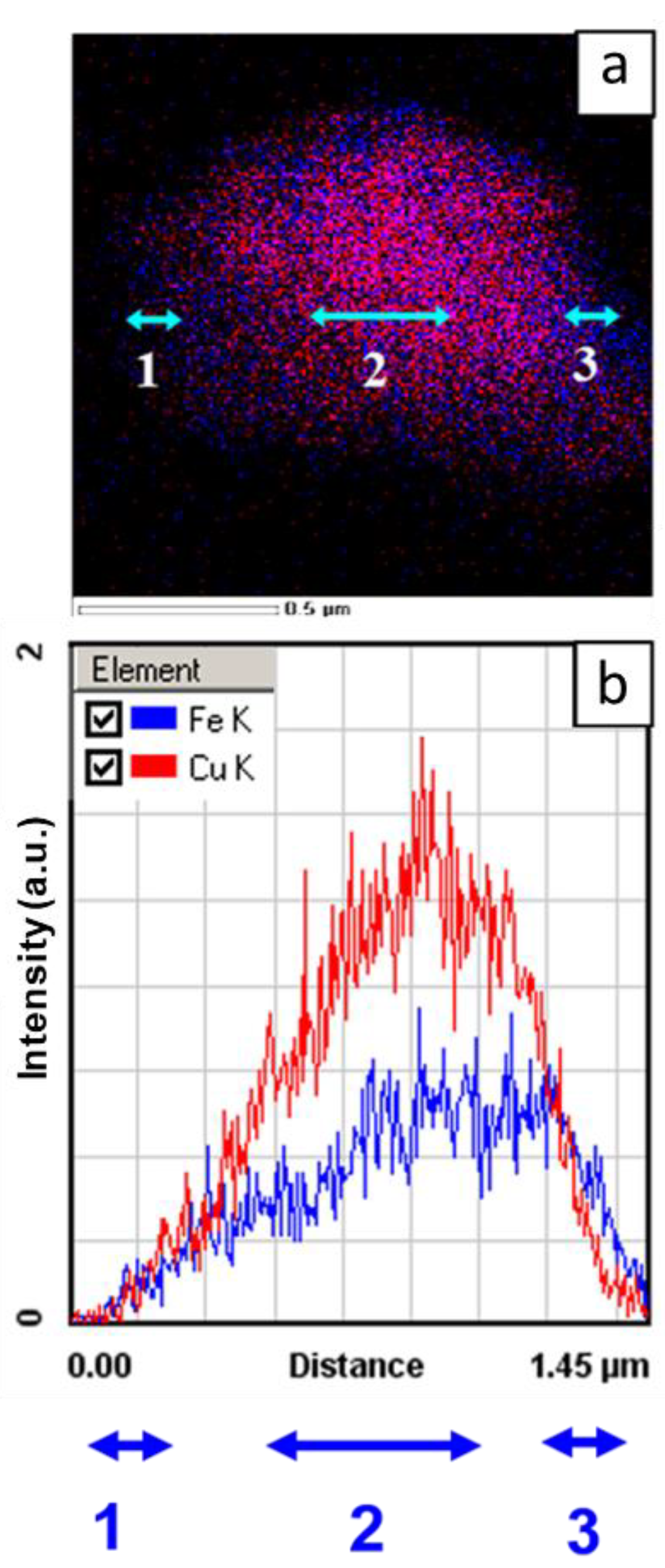
| Element | [keV] | Projection (1) [at.%] | Projection (2) [at.%] | Projection (3) [at.%] |
|---|---|---|---|---|
| Fe K | 6.398 | 68.9 | 17.2 | 68.6 |
| Cu K | 8.040 | 31.1 | 82.8 | 31.4 |
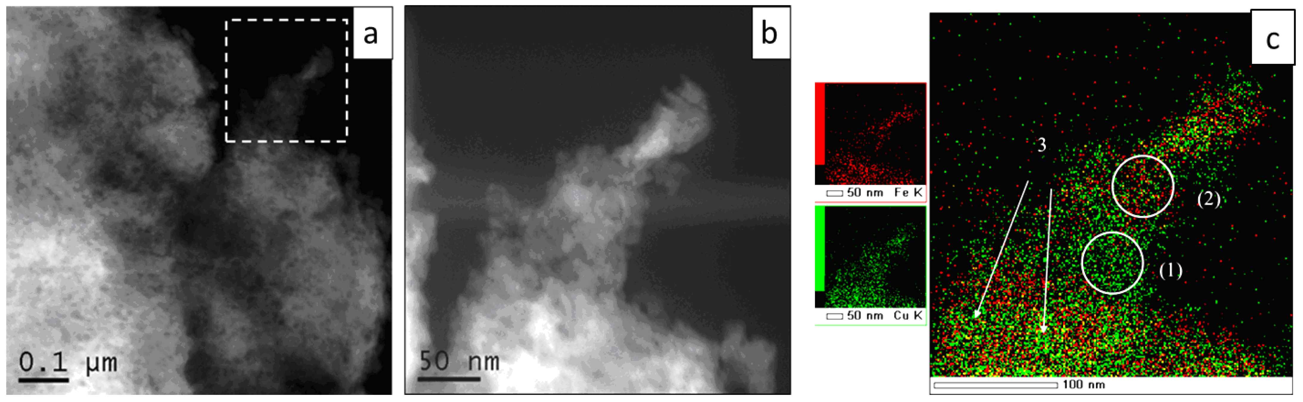
| Element | keV | Area (1) [at.%] | Area (2) [at.%] |
|---|---|---|---|
| Fe K | 6.398 | 6.6 | 23.6 |
| Cu K | 8.040 | 93.4 | 76.4 |
| Element | [keV] | Region (1) [at.%] | Region (2) [at.%] | Region (3) [at.%] | Region (4) [at.%] | Total, [at.%] |
|---|---|---|---|---|---|---|
| Al K | 1.486 | 4.1 | 3.2 | 8.1 | 88.93 | 3.59 |
| Fe K | 6.398 | 27.7 | 31.5 | 26.1 | 4.18 | 28.70 |
| Cu K | 8.040 | 68.2 | 65.3 | 65.8 | 6.89 | 66.71 |
Publisher’s Note: MDPI stays neutral with regard to jurisdictional claims in published maps and institutional affiliations. |
© 2022 by the authors. Licensee MDPI, Basel, Switzerland. This article is an open access article distributed under the terms and conditions of the Creative Commons Attribution (CC BY) license (https://creativecommons.org/licenses/by/4.0/).
Share and Cite
Tikhov, S.; Valeev, K.; Cherepanova, S.; Zaikovskii, V.; Salanov, A.; Sadykov, V.; Dudina, D.; Lomovsky, O.; Petrov, S.; Smorygo, O.; et al. Elimination of Composition Segregation in 33Al–45Cu–22Fe (at.%) Powder by Two-Stage High-Energy Mechanical Alloying. Materials 2022, 15, 2087. https://0-doi-org.brum.beds.ac.uk/10.3390/ma15062087
Tikhov S, Valeev K, Cherepanova S, Zaikovskii V, Salanov A, Sadykov V, Dudina D, Lomovsky O, Petrov S, Smorygo O, et al. Elimination of Composition Segregation in 33Al–45Cu–22Fe (at.%) Powder by Two-Stage High-Energy Mechanical Alloying. Materials. 2022; 15(6):2087. https://0-doi-org.brum.beds.ac.uk/10.3390/ma15062087
Chicago/Turabian StyleTikhov, Serguei, Konstantin Valeev, Svetlana Cherepanova, Vladimir Zaikovskii, Aleksei Salanov, Vladislav Sadykov, Dina Dudina, Oleg Lomovsky, Sergey Petrov, Oleg Smorygo, and et al. 2022. "Elimination of Composition Segregation in 33Al–45Cu–22Fe (at.%) Powder by Two-Stage High-Energy Mechanical Alloying" Materials 15, no. 6: 2087. https://0-doi-org.brum.beds.ac.uk/10.3390/ma15062087