
Physical and Numerical Simulations on Mechanical Properties of a Prefabricated Underground Utility Tunnel

 ,
,
Abstract
:1. Introduction
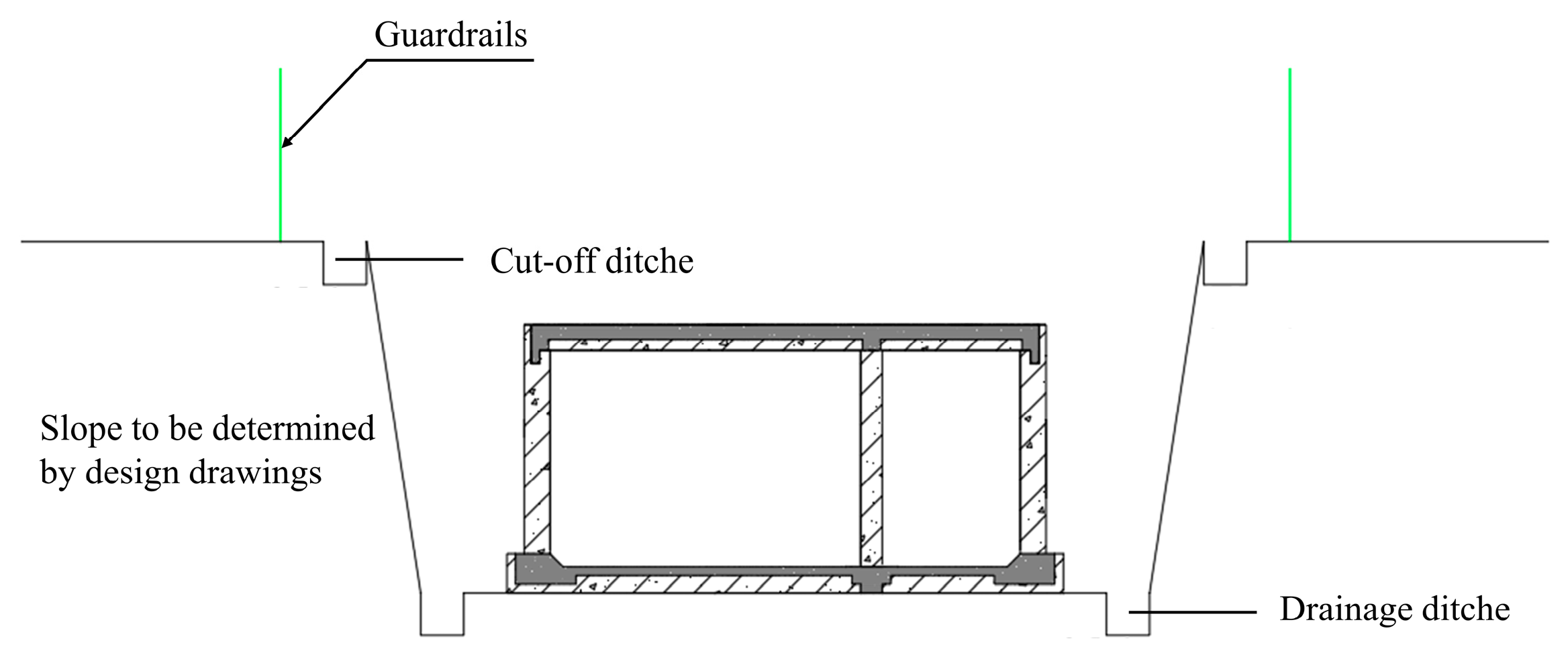
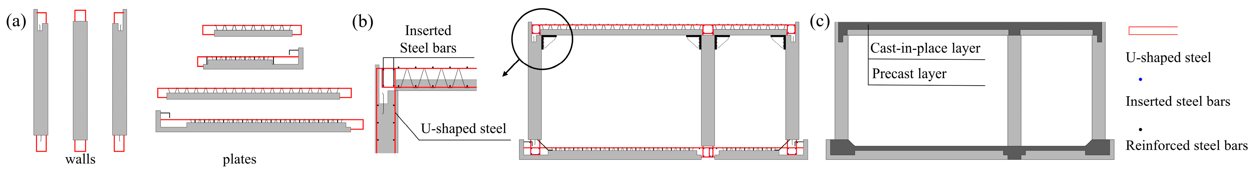
2. New Type of Prefabricated Underground Utility Tunnel
3. Experimental Study on the Mechanical Properties of Prefabricated Underground Utility Tunnels
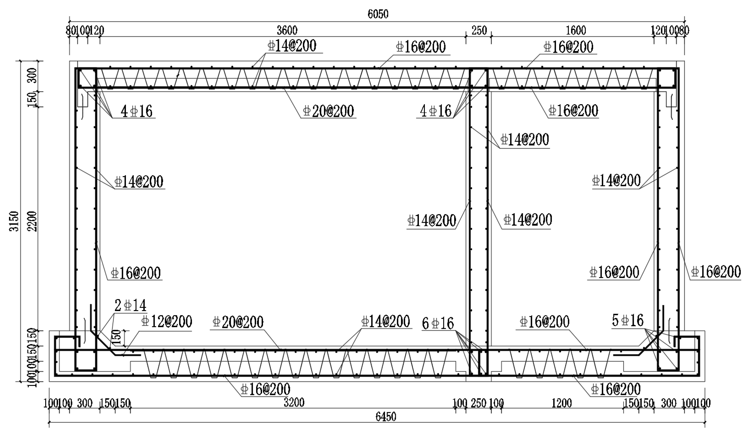
3.1. Specimen Fabrication
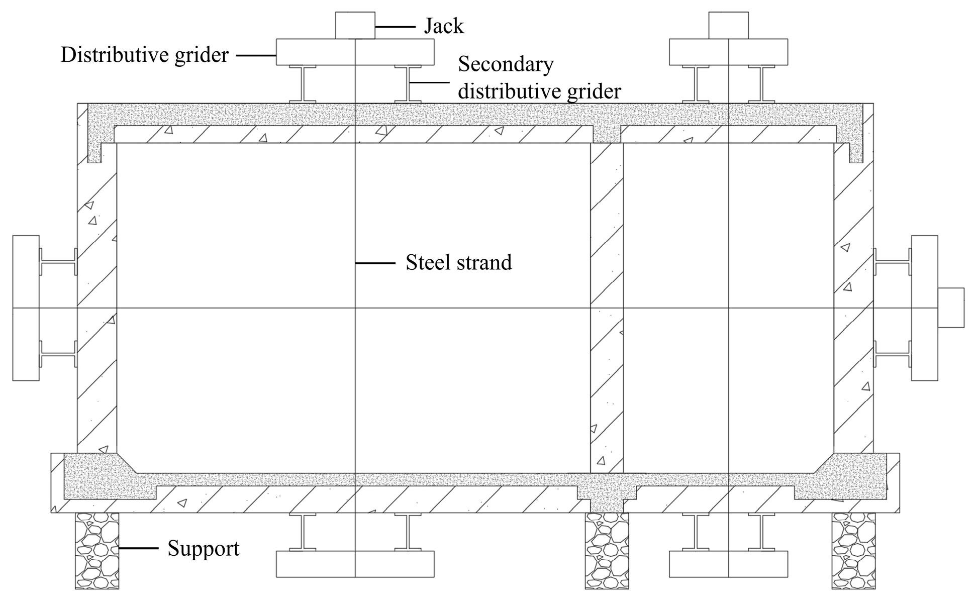
3.2. Test Loading
3.3. Test Results and Analyses of the Prefabricated Underground Utility Tunnel
3.3.1. Crack Development Process
3.3.2. Load-Deflection Curve
3.3.3. Analyses of Bearing Capacity Limit States
4. Numerical Simulations on Prefabricated Underground Utility Tunnels
4.1. Simulation of Material Constitutive Relationships and Laminated Surfaces
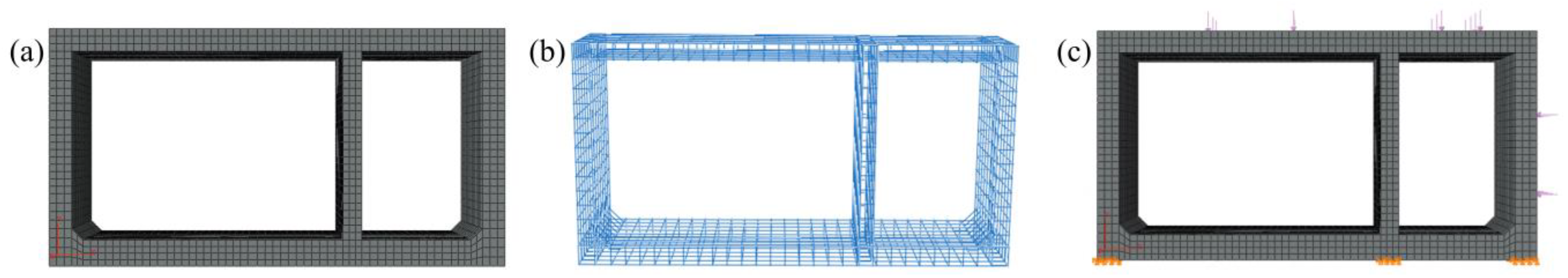
4.2. Establishment of the Finite Element Analysis Model
4.3. Finite Element Results and Analysis
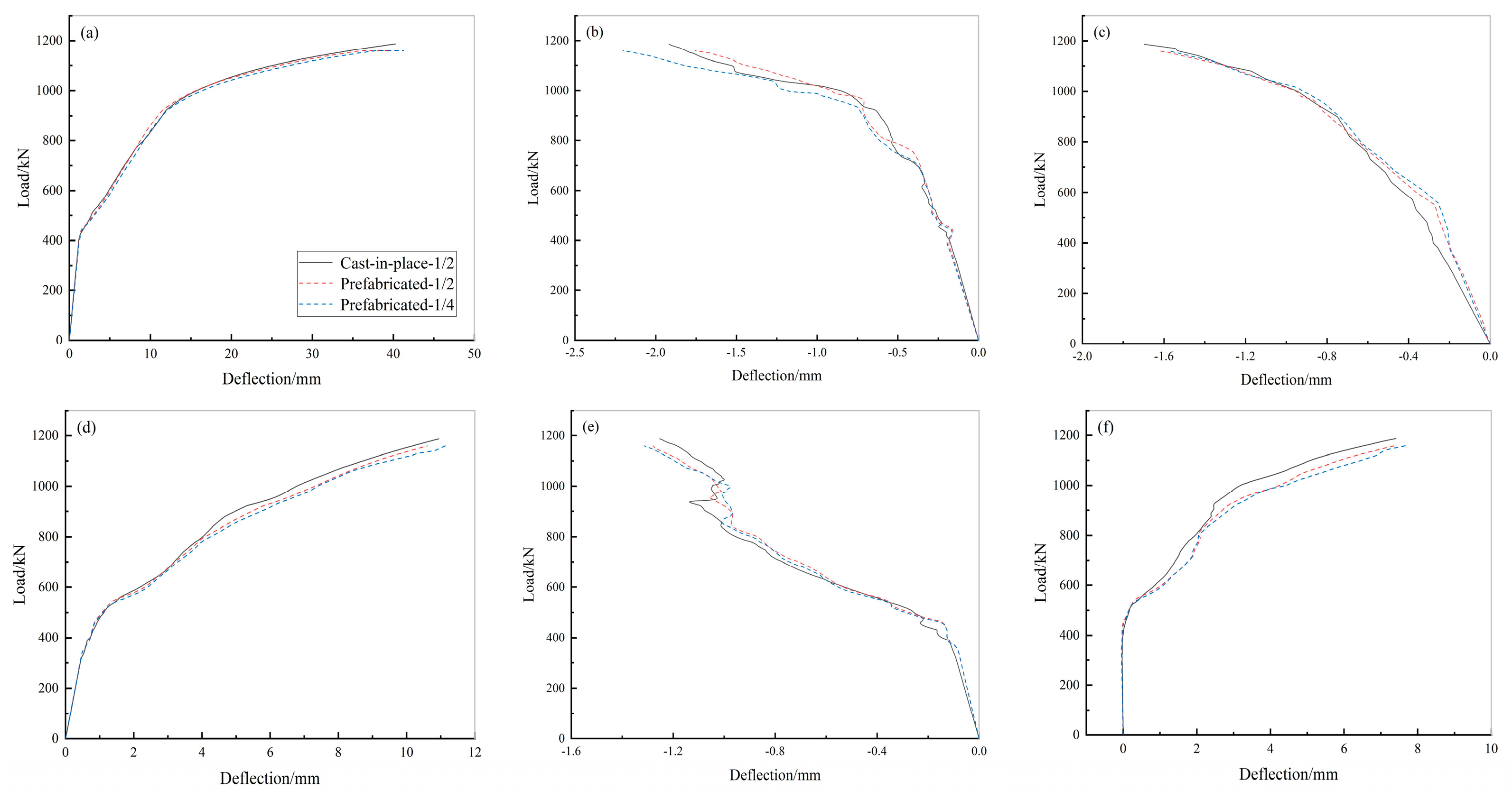
4.3.1. Load-Deflection Curves
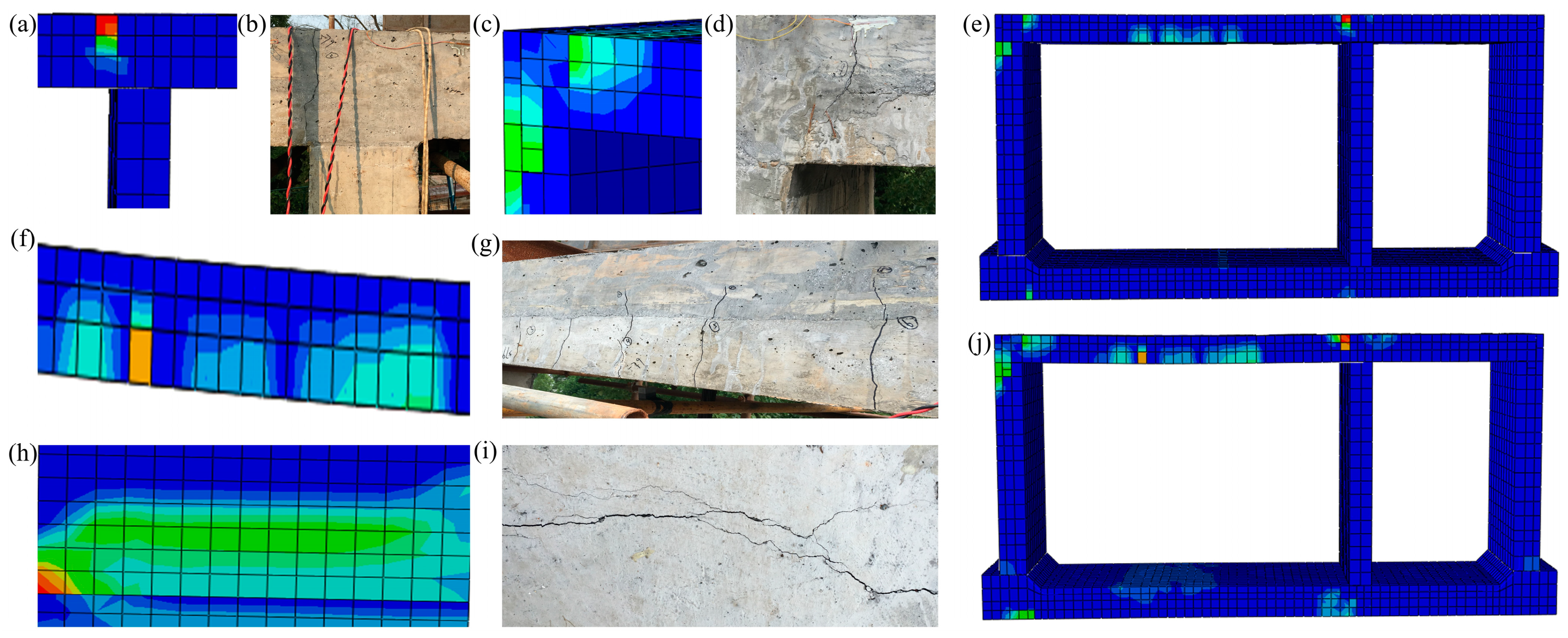
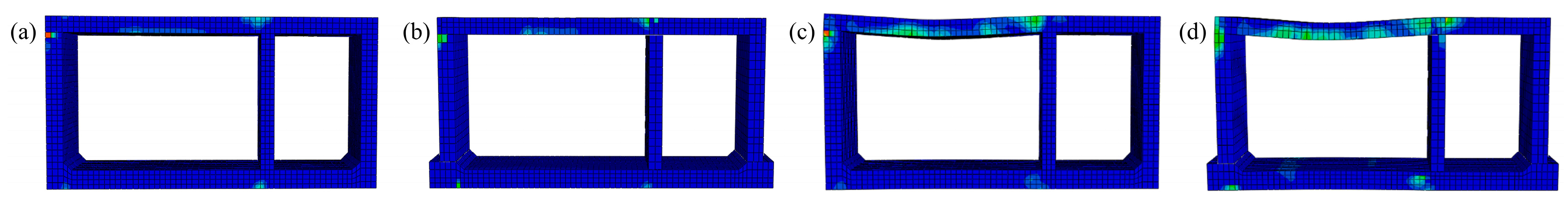
4.3.2. Crack Pattern Analyses
4.4. Comparative Analysis of Prefabricated and Cast-in-Place Underground Utility Tunnels
4.4.1. Establishment of the Finite Element Analysis Model for the Cast-in-Place Underground Utility Tunnel
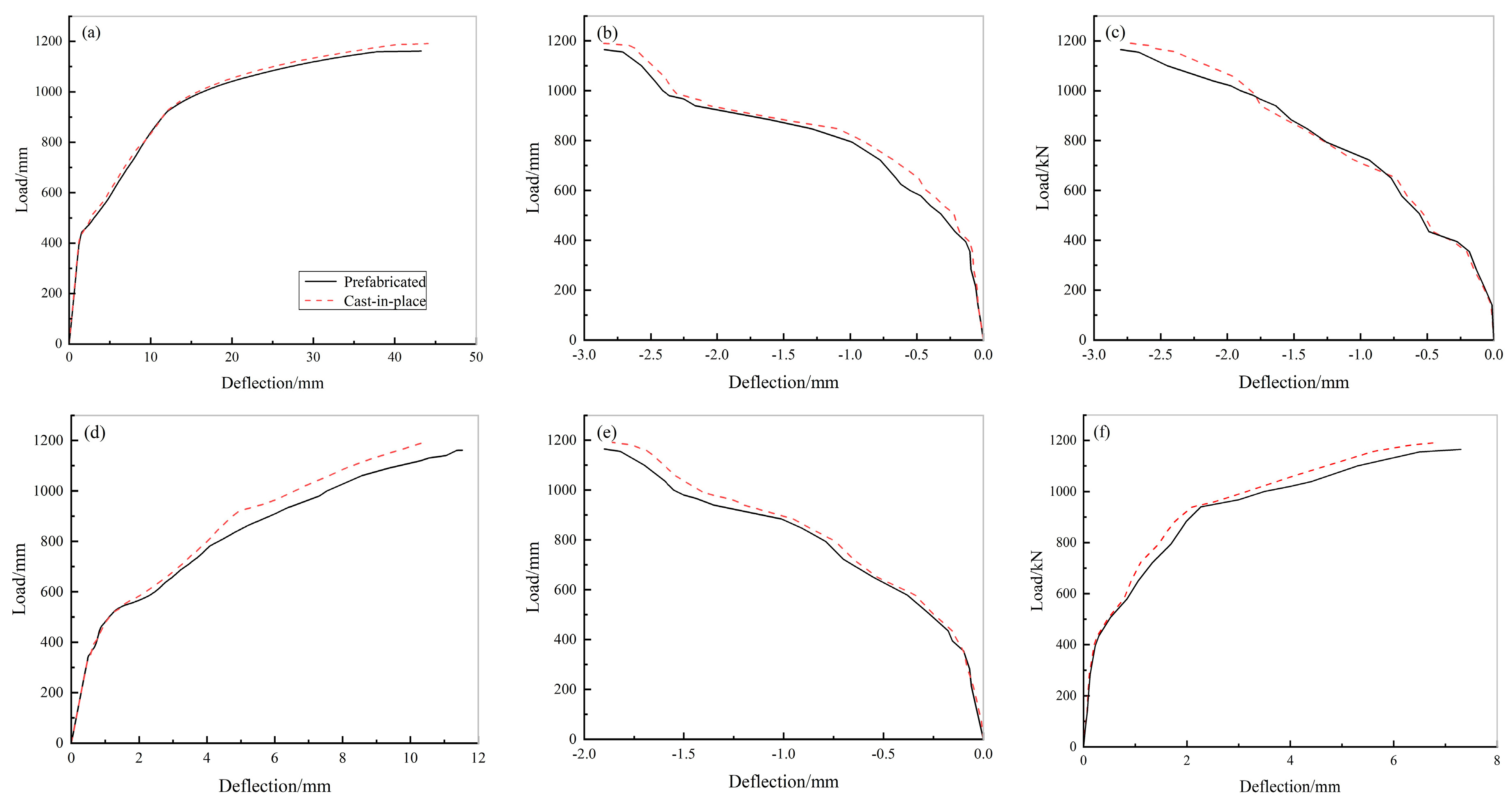
4.4.2. Load-Deflection Curves
4.4.3. Crack Analysis
4.5. Analysis of Longitudinal Connection of Sections on the Mechanical Properties of Prefabricated Underground Utility Tunnels
5. Conclusions
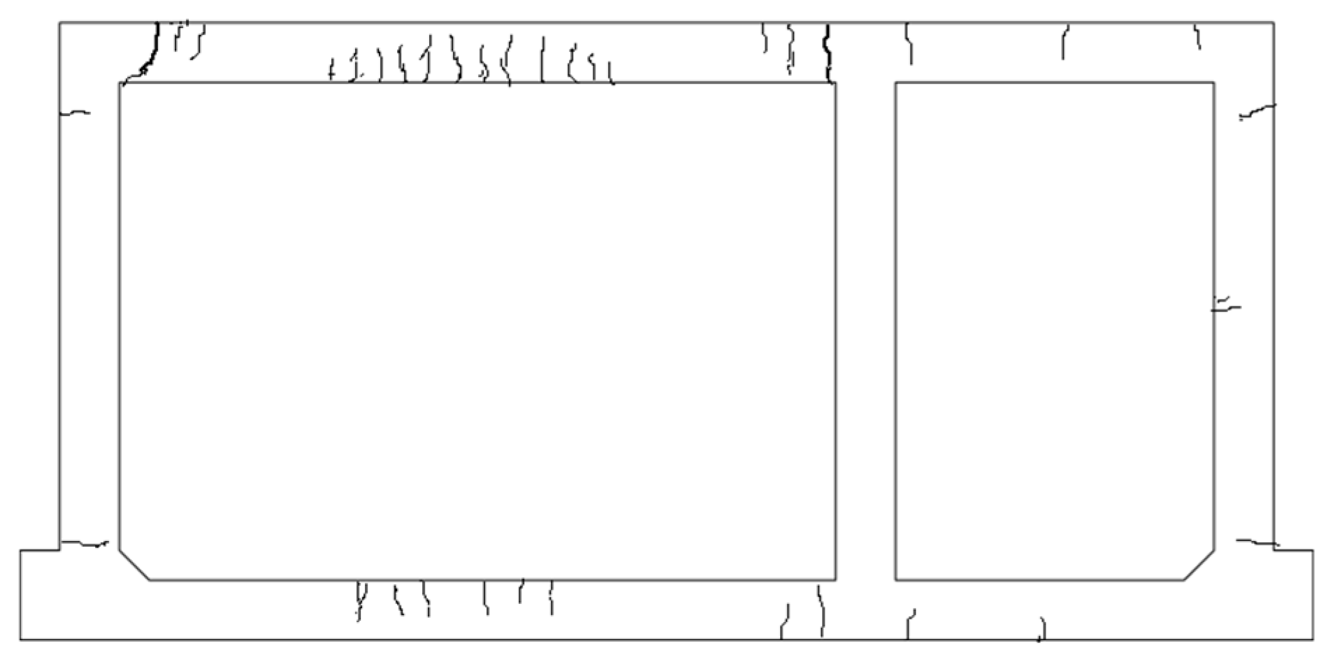
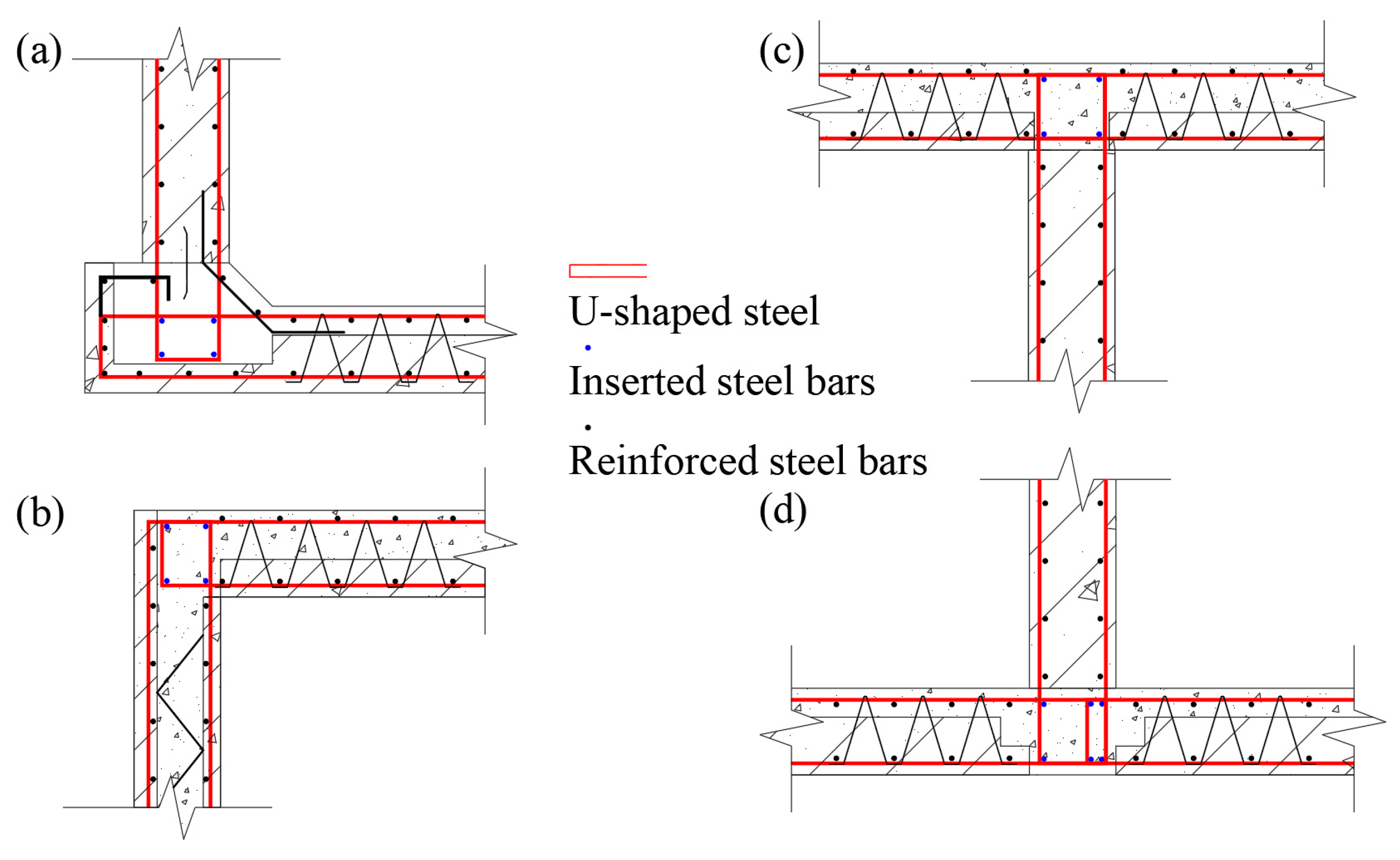
- The U-shaped ferrule joint bar connections are reliable. When the test is loaded to the tunnel design load value of 435 kN, the prefabricated double-cabin underground utility tunnel structure does not show any cracks. When it is loaded to 507 kN, the first crack appears 400 mm away from the middle-wall support in the top plate of the large span of the underground utility tunnel. When the load increases, the cracks develop continuously and they are mainly concentrated near the support and midspan of the wall or the plate structure of the tunnel.
- The ultimate bearing capacity of the prefabricated double-cabin underground utility tunnel is 3.71 times the load design value, while the ultimate bearing capacity meets the design requirements and has a large safety reserve.
- The load-deflection curves for both the cast-in-place and prefabricated underground utility tunnels are basically the same. The ultimate load of the prefabricated underground utility tunnel is 1162 kN and that of the cast-in-place underground utility tunnel is 1191 kN. The ultimate bearing capacity of the prefabricated underground utility tunnel is slightly less than that of the cast-in-place underground utility tunnel.
- The crack distribution pattern of cast-in-place and prefabricated underground utility tunnels is basically the same. The crack distribution range of prefabricated underground utility tunnels is slightly larger than that of cast-in-place utility tunnels and the cracking load is slightly smaller.
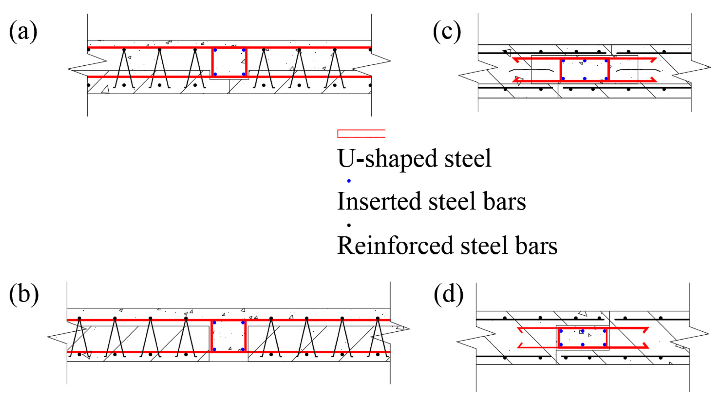
- The load-deflection curves of the measured points of the cast-in-place utility tunnel as well as the longitudinal section connection and non-section connection of the prefabricated utility tunnel are all very similar. The ultimate load capacity of the double-section prefabricated underground utility tunnel is 1159 kN and that of the double-section cast-in-place utility tunnel is 1187 kN. The longitudinal joint connections of the prefabricated utility tunnel allow the structure, as a whole, to maintain favourable mechanical properties.
Author Contributions
Funding
Institutional Review Board Statement
Informed Consent Statement
Data Availability Statement
Acknowledgments
Conflicts of Interest
Appendix A


References
- He, C.; Xie, Q.; Jiang, L.; Jiang, L.; Yang, Z. Numerical model of large spatial deflections of bundled conductors in electrical substations. Int. J. Mech. Mater. Des. 2022, 18, 223–242. [Google Scholar] [CrossRef]
- Qian, Q.; Chen, X. Situation, problems and countermeasures of utility tunnel development in china and abroad. Chin. J. Undergr. Space Eng. 2007, 3, 191–194. [Google Scholar]
- Zhang, Z. Research on management and development of urban underground pipeline galleries at home and abroad. Constr. Sci. Technol. 2018, 24, 42–52+59. [Google Scholar] [CrossRef]
- Broere, W. Urban underground space: Solving the problems of today’s cities. Tunn. Undergr. Space Technol. 2016, 55, 245–248. [Google Scholar] [CrossRef] [Green Version]
- Yu, C.; Zhang, Z. The development history and current situation of urban underground comprehensive pipe corridors at home and abroad. Constr. Sci. Technol. 2015, 17, 49–51. [Google Scholar] [CrossRef]
- Wang, H. Several Problems about Urban Underground Utility Tunnel during Construction in China. Tunn. Constr. 2017, 37, 523–528. [Google Scholar] [CrossRef]
- Jiang, L.; Jiang, L.; Ye, J.; Hu, Y.; Zheng, H. Macroscopic modelling of steel frames equipped with bolt-connected reinforced concrete panel wall. Eng. Struct. 2020, 213, 110549. [Google Scholar] [CrossRef]
- Qiu, D.; Pan, F.; Zhang, C.; Han, Y. Introduction of green construction technology in prefabricated building. GreenBuild. 2016, 8, 62–63+67. [Google Scholar]
- Garg, A.K.; Abolmaali, A.; Fernandez, R. Experimental investigation of shear capacity of precast reinforced concrete box culverts. J. Bridge Eng. 2007, 12, 511–517. [Google Scholar] [CrossRef]
- Fang, Z.; Jin, Y.; Guo, F.; Zhang, D.; Mo, C.; Huang, S. Experimental research on mechnical properties of assembled monolithic concrete utility tunnels. Ind. Constr. 2021, 51, 47–56. [Google Scholar] [CrossRef]
- Hu, X.; Xue, W. Experimental study of mechanical properties of PPMT. Chin. Civ. Eng. J. 2010, 43, 29–37. [Google Scholar] [CrossRef]
- Tian, Z. Experimental Research on Force Performance of Precast Concrete Underground Comprehensive Municipal Tunnel. Master’s Thesis, Harbin Institute of Technology, Harbin, China, 2016. [Google Scholar]
- Wei, Q.; Wang, Y.; Wang, Y.; Pi, Z.; Liao, X.; Wang, S.; Zhang, H. Experiment study on seismic performance of joints in prefabricated sandwich structures of utility tunnels. J. Build. Struct. 2019, 40, 246–254. [Google Scholar] [CrossRef]
- Huang, W. Study on Seismic Dynamic Response of Prefabricated Urban Underground Comprehensive Pipe Gallery; Southwest Jiaotong University: Chengdu, China, 2018. [Google Scholar]
- Yi, W.; Yan, L.; Peng, Z. Static Load and finnite element analysis on full-scale model of utility tunnel structure without axillary angle. J. Hunan Univ. Nat. Sci. 2019, 46, 1–10. [Google Scholar] [CrossRef]
- Gebretsadik, B.; Jdidirendi, K.; Farhangi, V.; Karakouzian, M. Application of Ultrasonic Measurements for the Evaluation of Steel Fiber Reinforced Concrete. Eng. Technol. Appl. Sci. Res. 2021, 11, 6662–6667. [Google Scholar] [CrossRef]
- Code of China, GB/T 50152-2012; Standard for Test Method of Concrete Structures. China Architecture & Building Press: Beijing, China, 2012.
- Hoffmire, C.A.; Monteith, L.L.; Holliday, R.; Park, C.L.; Brenner, L.A.; Hoff, R.A. Administrative military discharge and suicidal ideation among post-9/11 veterans. Am. J. Prev. Med. 2019, 56, 727–735. [Google Scholar] [CrossRef] [PubMed]
- Code of China, GB 50010-2010; Code for Design of Concrete Structures. China Architecture & Building Press: Beijing, China, 2010.
- CEB-FIP Model Code 1990: Design Code; Amer Society of Civil Engineers: London, UK, 1993.
- Code of American, ACI 318-95; Building Code Requirement for Structural Concrete and Commentary. American Concrete Institute: Farmington Hills, MI, USA, 1995.


| Steel Grade | Diameter/mm | Yield Strength fy/Mpa | Ultimate Strength fu/Mpa |
|---|---|---|---|
| HRB400 | 12 | 428 | 616 |
| HRB400 | 14 | 419 | 592 |
| HRB400 | 16 | 446 | 622 |
| HRB400 | 20 | 453 | 641 |
| Loading Grade | Large-Span Plate/kN | Small-Span Plate/kN | Lateral Wall/kN |
|---|---|---|---|
| 1 | 71 | 32 | 47 |
| 2 | 142 | 64 | 94 |
| 3 | 213 | 96 | 141 |
| 4 | 284 | 128 | 188 |
| 5 (standard value) | 355 | 160 | 235 |
| 6 | 395 | 178 | 262 |
| 7 (design value) | 435 | 196 | 289 |
| 8 | 507 | 229 | 336 |
| 9 | 579 | 261 | 383 |
| 10 | 650 | 293 | 430 |
| 11 | 722 | 325 | 478 |
| 12 | 794 | 358 | 526 |
| 13 | 848 | 382 | 561 |
| 14 | 884 | 398 | 585 |
| 15 | 940 | 424 | 622 |
| Section Position | Tensile Reinforcement/mm2 | Compressed Reinforcement/mm2 | Bending Capacity/kN·m |
|---|---|---|---|
| Lateral support | 2199 | 2199 | 386.5 |
| Midspan | 2199 | 1407 | 339.7 |
| Middle support | 2199 | 2199 | 386.5 |
| Ѱ (°) | ϵ | fb0/fc0 | K | μ |
|---|---|---|---|---|
| 30 | 0.1 | 1.16 | 0.6667 | 0.0005 |
| Measuring Points | Experimental Value/mm | Finite Element Value/mm | Relative Error |
|---|---|---|---|
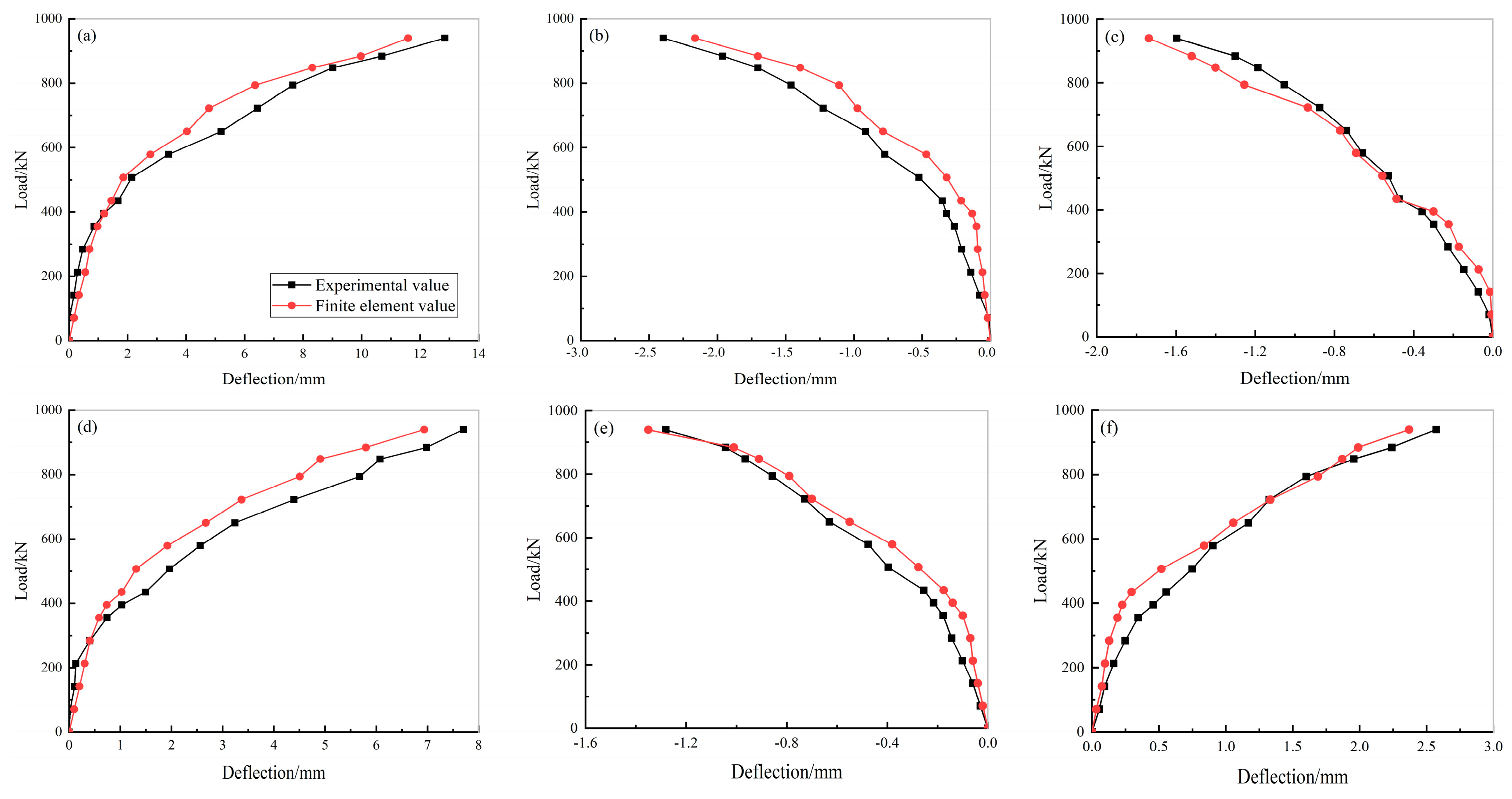
| Large-span top plate | 12.845 | 11.593 | 9.75% |
| Small-span top plate | −2.396 | −2.164 | 9.68% |
| Large-span lateral wall | −1.597 | −1.737 | 8.76% |
| Large-span bottom plate | 7.703 | 6.937 | 9.94% |
| Small-span bottom plate | −1.281 | −1.350 | 5.39% |
| Small-span lateral wall | 2.572 | 2.370 | 7.85% |
Publisher’s Note: MDPI stays neutral with regard to jurisdictional claims in published maps and institutional affiliations. |
© 2022 by the authors. Licensee MDPI, Basel, Switzerland. This article is an open access article distributed under the terms and conditions of the Creative Commons Attribution (CC BY) license (https://creativecommons.org/licenses/by/4.0/).
Share and Cite
Kuang, Y.; Peng, Z.; Yang, J.; Zhou, M.; He, C.; Liu, Y.; Mo, X.; Song, Z. Physical and Numerical Simulations on Mechanical Properties of a Prefabricated Underground Utility Tunnel. Materials 2022, 15, 2276. https://0-doi-org.brum.beds.ac.uk/10.3390/ma15062276
Kuang Y, Peng Z, Yang J, Zhou M, He C, Liu Y, Mo X, Song Z. Physical and Numerical Simulations on Mechanical Properties of a Prefabricated Underground Utility Tunnel. Materials. 2022; 15(6):2276. https://0-doi-org.brum.beds.ac.uk/10.3390/ma15062276
Chicago/Turabian StyleKuang, Yachuan, Zhiwei Peng, Jiahui Yang, Miaomiao Zhou, Chang He, Yinhu Liu, Xiaofei Mo, and Zhexuan Song. 2022. "Physical and Numerical Simulations on Mechanical Properties of a Prefabricated Underground Utility Tunnel" Materials 15, no. 6: 2276. https://0-doi-org.brum.beds.ac.uk/10.3390/ma15062276