
Design and Validation of Additively Manufactured Metallic Cellular Scaffold Structures for Bone Tissue Engineering

 , , , and
Abstract
:1. Introduction
2. Material and Methods
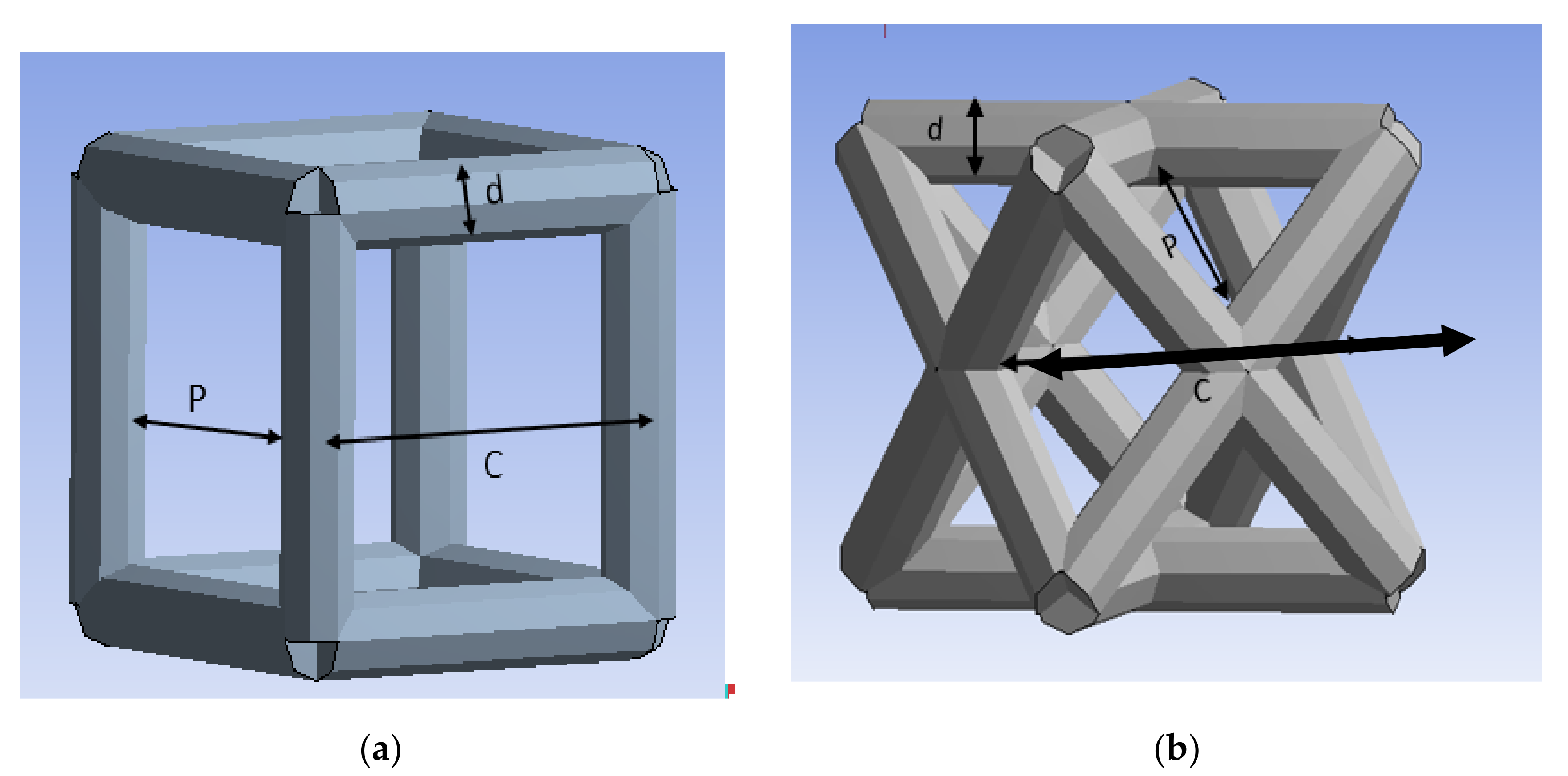
2.1. BTE Scaffold Material
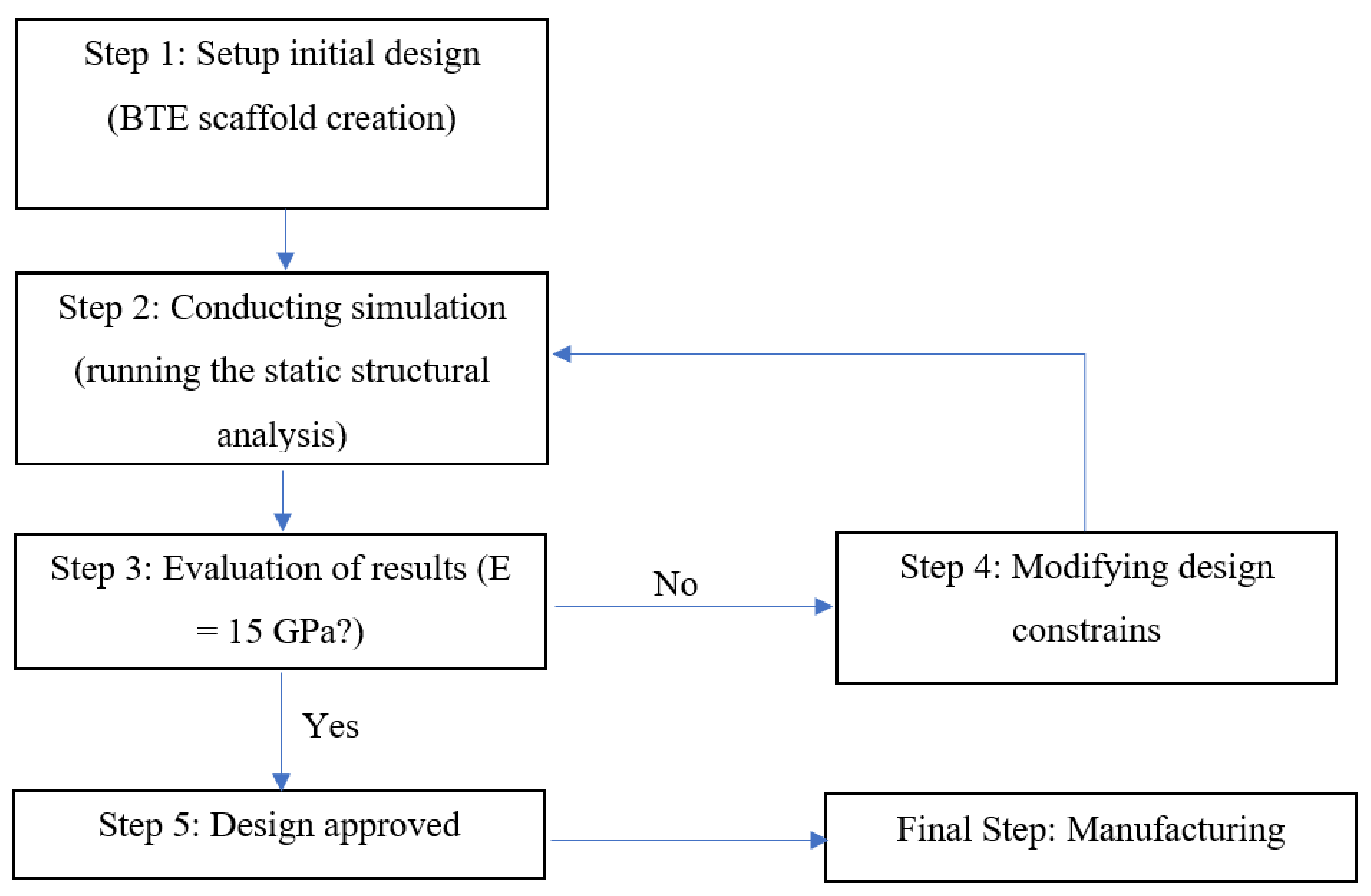
2.2. Finite Element Analysis Approach
2.3. Bending and Torsional Stiffnesses
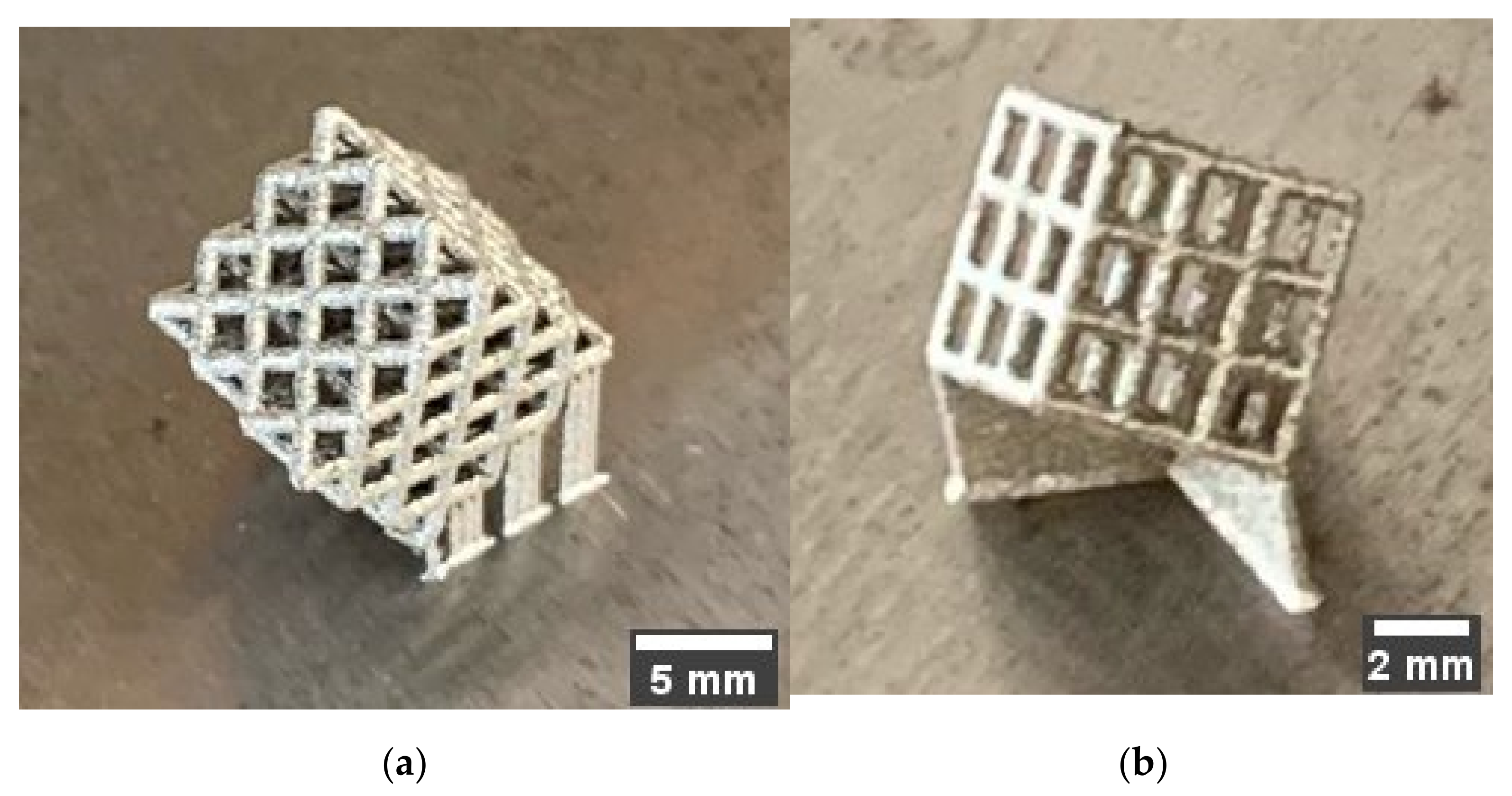
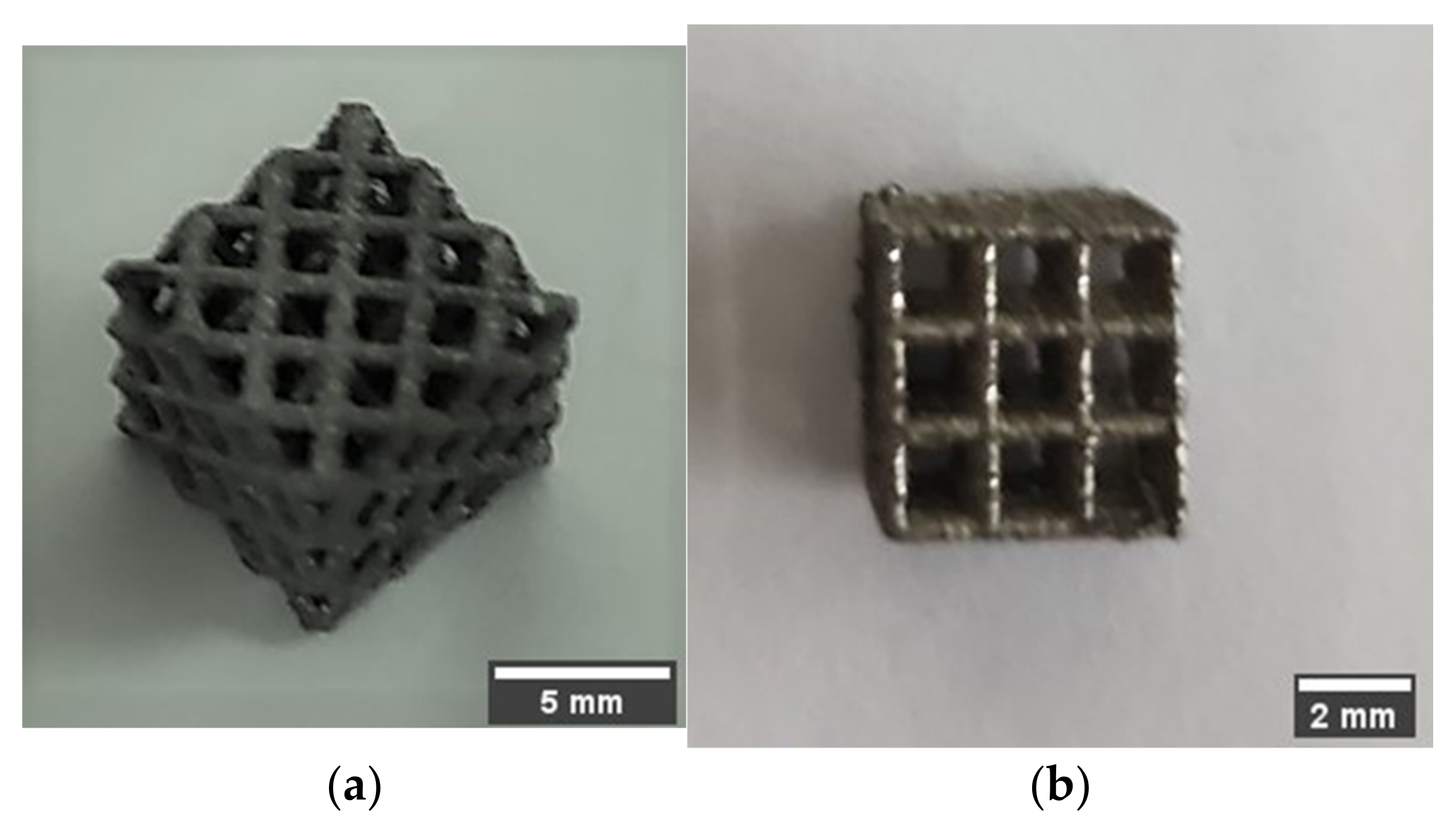
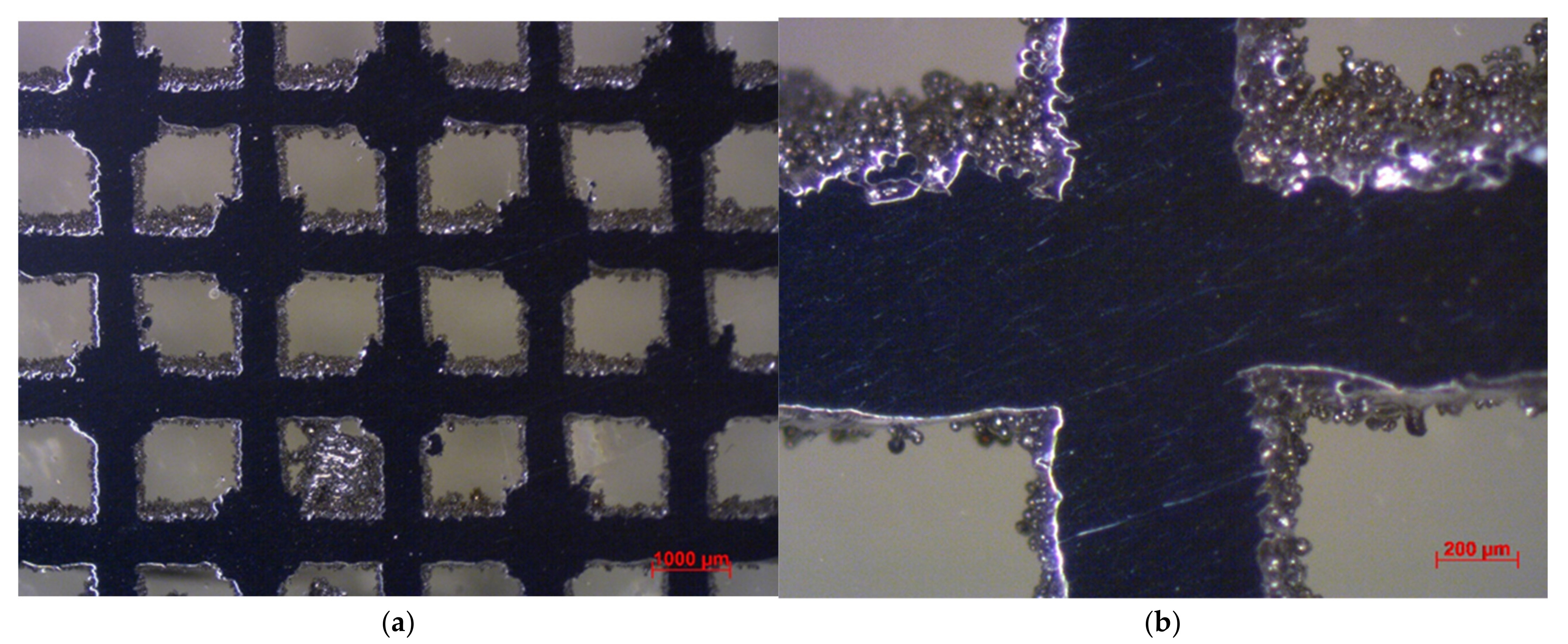
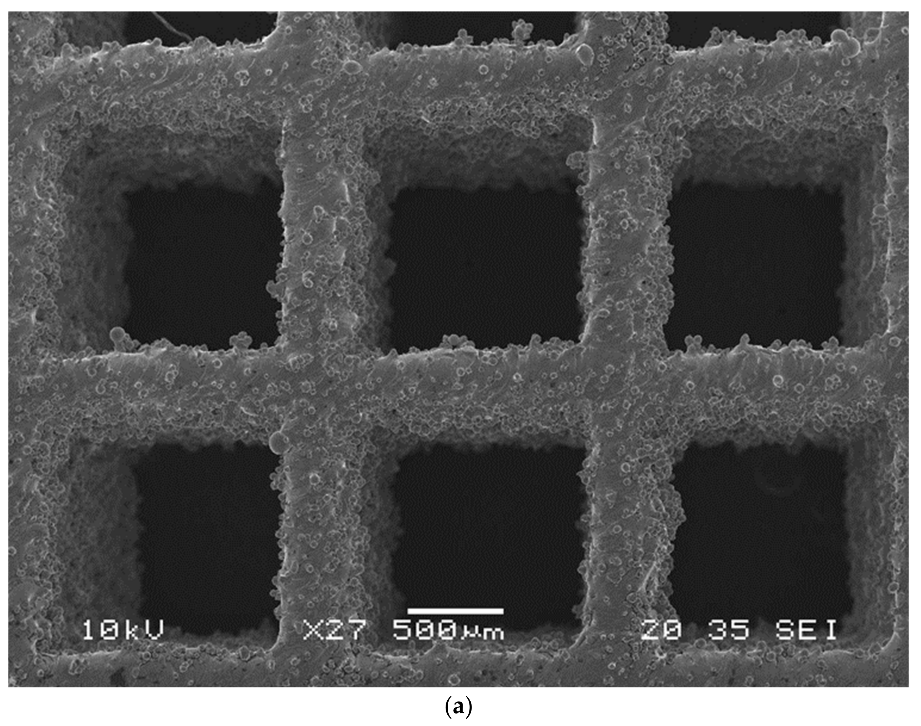
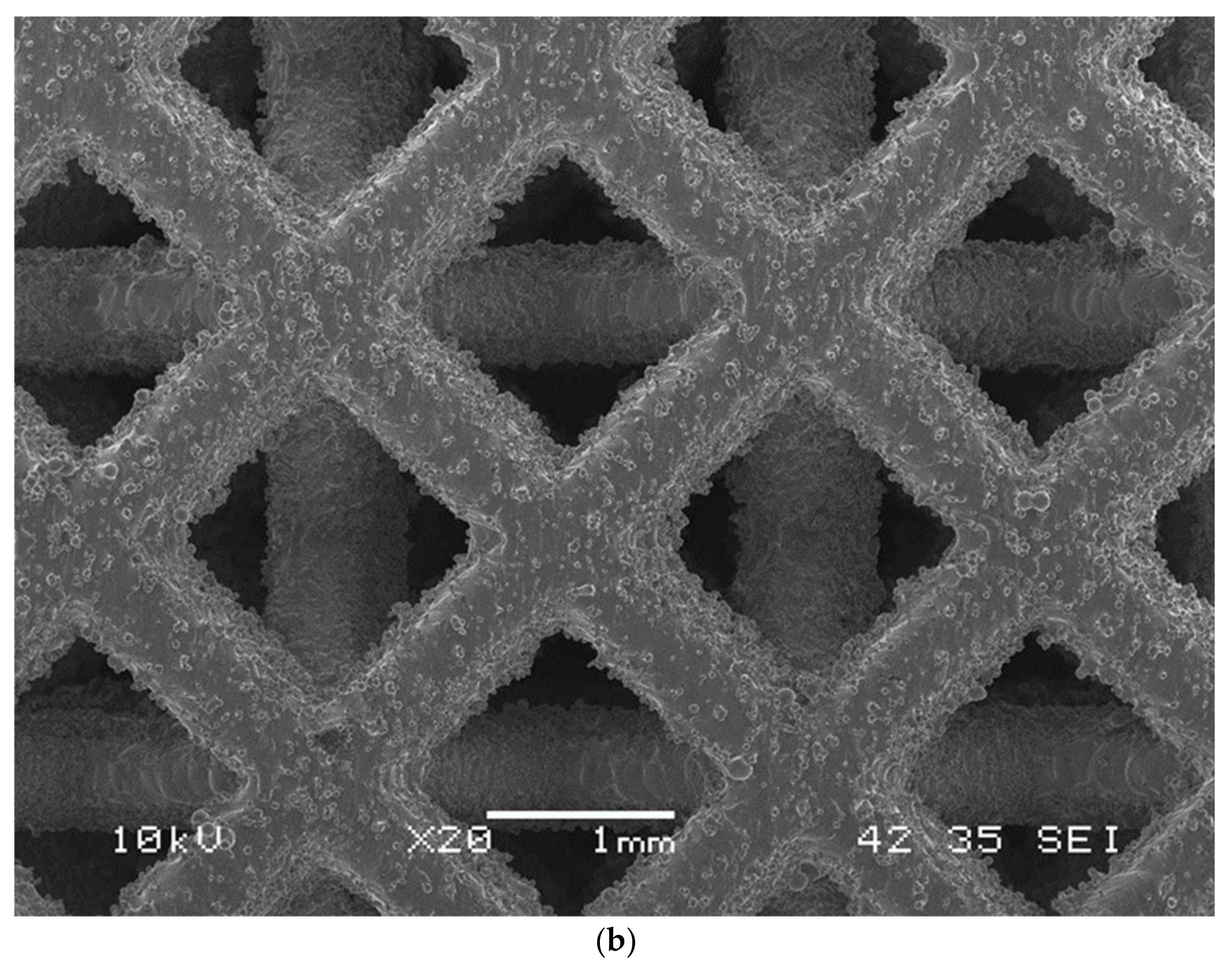
2.4. Additive Manufacturing and Structural Characterization
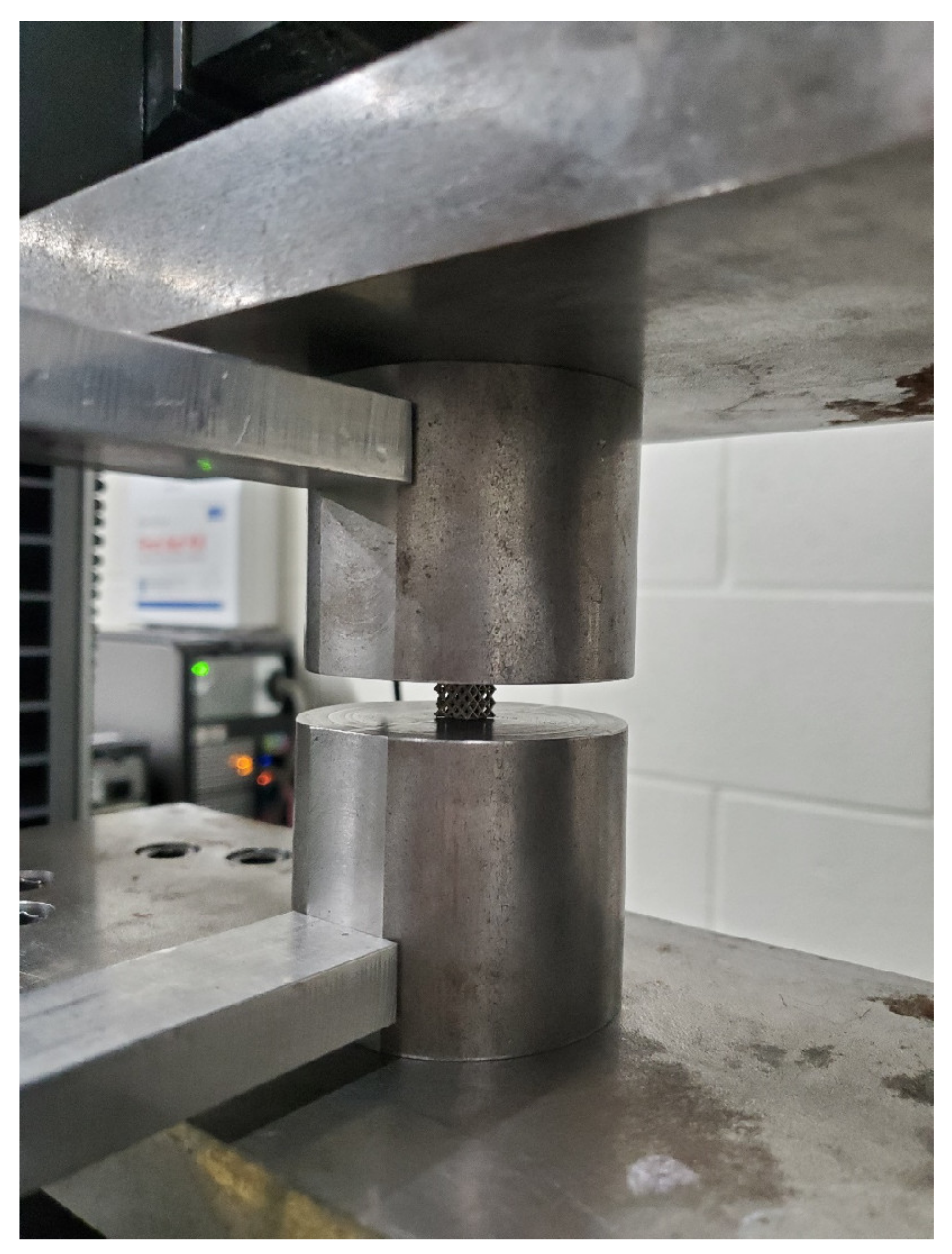
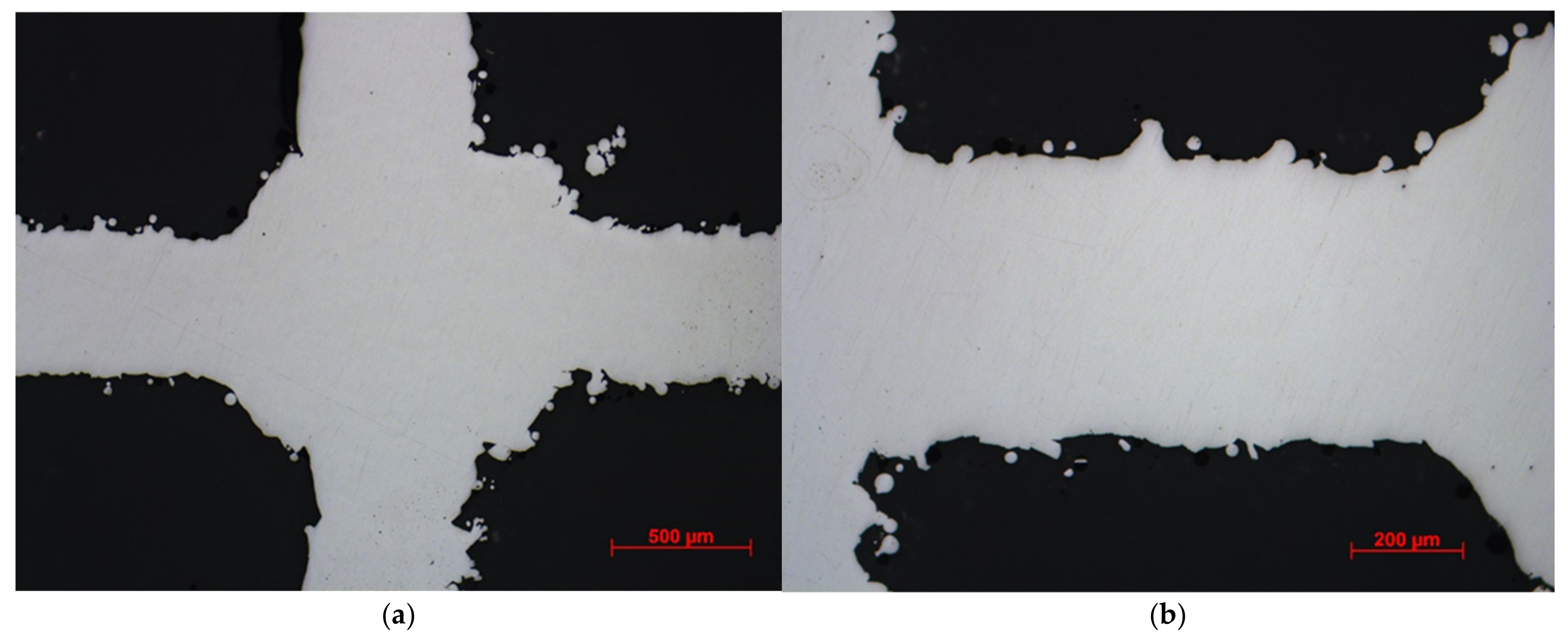
2.5. Mechanical Testing and Morphological Characterization
3. Results and Discussion
3.1. Optimization Results and Morphological Properties
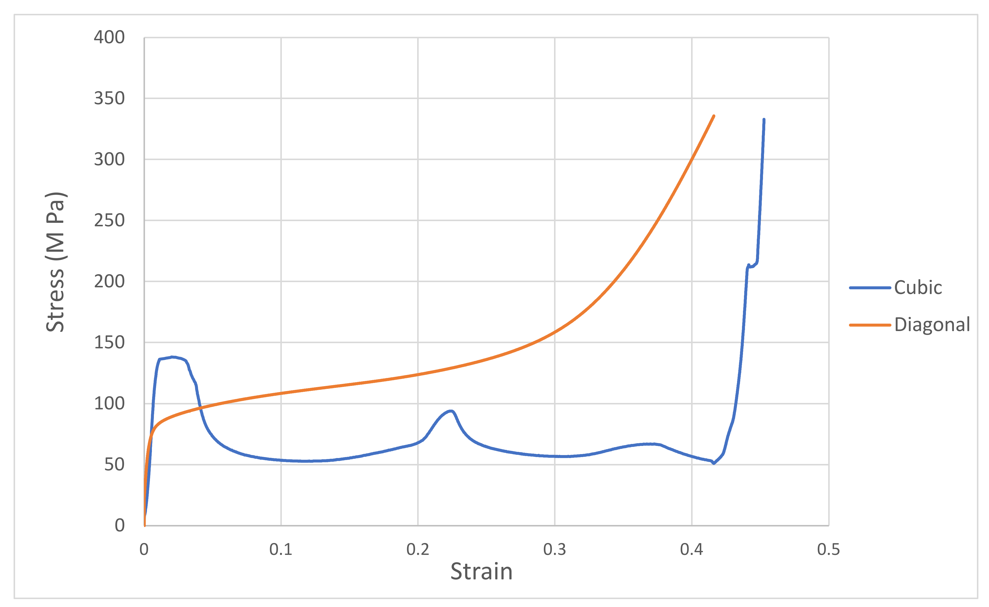
3.2. Validating FEA Results by Experimental Testing
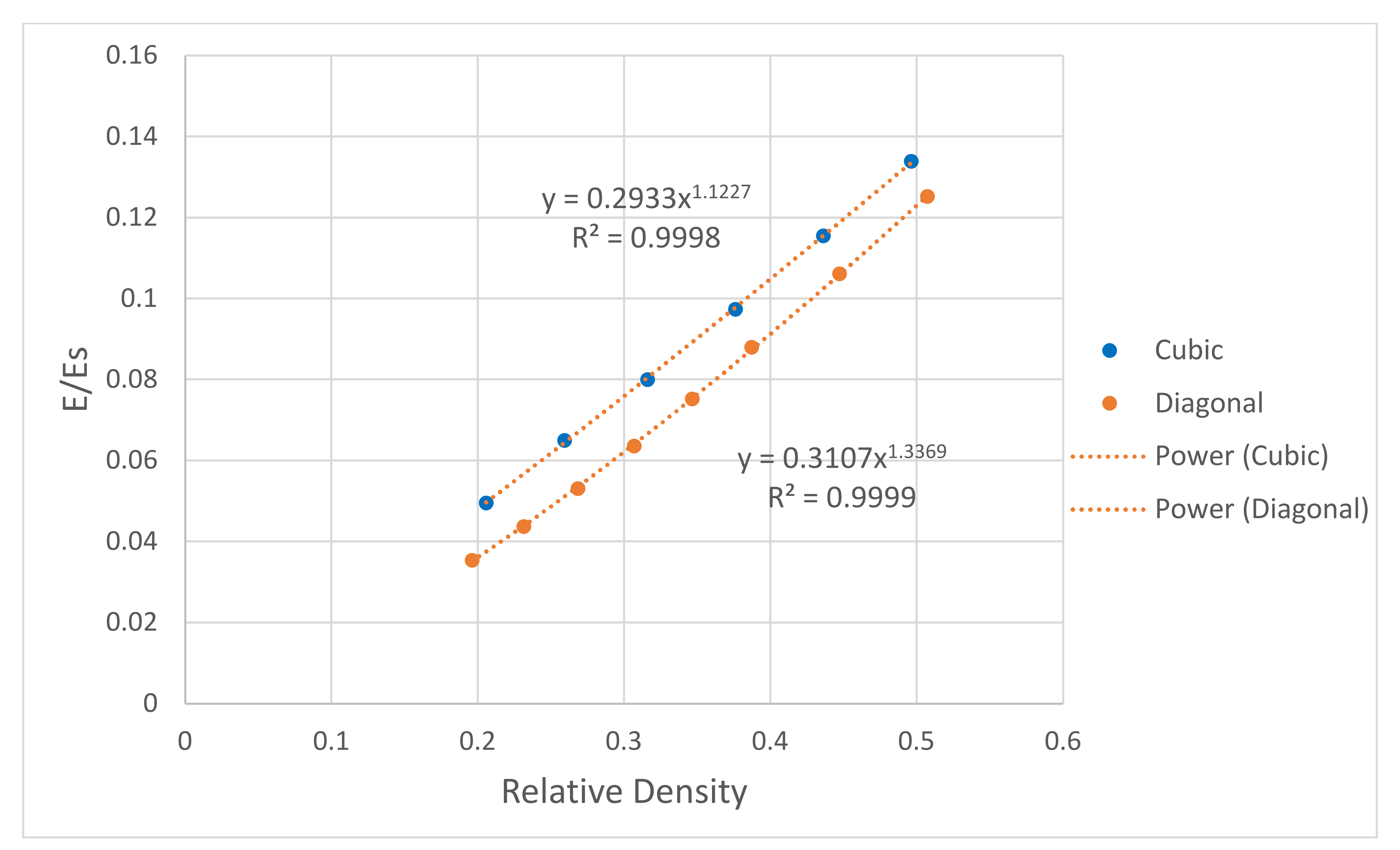
3.3. Bending, Shear, and Effect of Porosity
4. Conclusions
Author Contributions
Funding
Institutional Review Board Statement
Informed Consent Statement
Data Availability Statement
Conflicts of Interest
References
- Ramalingam, M.; Haidar, Z.; Ramakrishna, S. Integrated Biomaters for Biomedical Technology; John Wiley & Sons: Hoboken, NJ, USA, 2012. [Google Scholar]
- Giannoudis, P.V.; Dinopoulos, H.; Tsiridis, E. Bone substitutes: An update. Injury 2005, 36, S20–S27. [Google Scholar] [CrossRef] [PubMed]
- Jukes, J.M.; Both, S.K.; Leusink, A.; Sterk, L.M.T.; van Blitterswijk, C.A.; de Boer, J. Endochondral bone tissue engineering using embryonic stem cells. Proc. Natl. Acad. Sci. USA 2008, 105, 6840–6845. [Google Scholar] [CrossRef] [PubMed] [Green Version]
- Alvarez, K.; Nakajima, H. Metallic Scaffolds for Bone Regeneration. Materials 2009, 2, 790–832. [Google Scholar] [CrossRef]
- Bose, S.; Vahabzadeh, S.; Bandyopadhyay, A. Bone tissue engineering using 3D printing. Mater. Today 2013, 16, 496–504. [Google Scholar] [CrossRef]
- Yu, J.; Xia, H.; Ni, Q.-Q. A three-dimensional porous hydroxyapatite nanocomposite scaffold with shape memory effect for bone tissue engineering. J. Mater. Sci. 2018, 53, 4734–4744. [Google Scholar] [CrossRef]
- Tamimi, F.; Torres, J.; Al-Abedalla, K.; Lopez-Cabarcos, E.; Alkhraisat, M.H.; Bassett, D.C.; Gbureck, U.; Barralet, J.E. Osseointegration of dental implants in 3D-printed synthetic onlay grafts customized according to bone metabolic activity in recipient site. Biomaterials 2014, 35, 5436–5445. [Google Scholar] [CrossRef]
- Ponader, S.; von Wilmowsky, C.; Widenmayer, M.; Lutz, R.; Heinl, P.; Körner, C.; Singer, R.F.; Nkenke, E.; Neukam, F.W.; Schlegel, K.A. In vivo performance of selective electron beam-melted Ti-6Al-4V structures. J. Biomed. Mater. Res. Part A 2010, 92, 56–62. [Google Scholar] [CrossRef]
- Ryan, G.E.; Pandit, A.S.; Apatsidis, D.P. Porous titanium scaffolds fabricated using a rapid prototyping and powder metallurgy technique. Biomaterials 2008, 29, 3625–3635. [Google Scholar] [CrossRef]
- Van der Stok, J.; Wang, H.; Amin Yavari, S.; Siebelt, M.; Sandker, M.; Waarsing, J.H.; Verhaar, J.A.N.; Jahr, H.; Zadpoor, A.A.; Leeuwenburgh, S.C.G.; et al. Enhanced bone regeneration of cortical segmental bone defects using porous titanium scaffolds incorporated with colloidal gelatin gels for time- and dose-controlled delivery of dual growth factors. Tissue Eng. Part A 2013, 19, 2605–2614. [Google Scholar] [CrossRef] [Green Version]
- Itälä, A.I.; Ylänen, H.O.; Ekholm, C.; Karlsson, K.H.; Aro, H.T. Pore diameter of more than 100 microm is not requisite for bone ingrowth in rabbits. J. Biomed. Mater. Res. 2001, 58, 679–683. [Google Scholar] [CrossRef]
- Murphy, C.M.; Haugh, M.G.; O’Brien, F.J. The effect of mean pore size on cell attachment, proliferation and migration in collagen-glycosaminoglycan scaffolds for bone tissue engineering. Biomaterials 2010, 31, 461–466. [Google Scholar] [CrossRef] [PubMed]
- Hollander, D.A.; von Walter, M.; Wirtz, T.; Sellei, R.; Schmidt-Rohlfing, B.; Paar, O.; Erli, H.-J. Structural, mechanical and in vitro characterization of individually structured Ti–6Al–4V produced by direct laser forming. Biomaterials 2006, 27, 955–963. [Google Scholar] [CrossRef] [PubMed]
- Lopez-Heredia, M.A.; Goyenvalle, E.; Aguado, E.; Pilet, P.; Leroux, C.; Dorget, M.; Weiss, P.; Layrolle, P. Bone growth in rapid prototyped porous titanium implants. J. Biomed. Mater. Res. A 2008, 85, 664–673. [Google Scholar] [CrossRef] [PubMed]
- Van Bael, S.; Chai, Y.C.; Truscello, S.; Moesen, M.; Kerckhofs, G.; Van Oosterwyck, H.; Kruth, J.-P.; Schrooten, J. The effect of pore geometry on the in vitro biological behavior of human periosteum-derived cells seeded on selective laser-melted Ti6Al4V bone scaffolds. Acta Biomater. 2012, 8, 2824–2834. [Google Scholar] [CrossRef]
- Holy, C.E.; Shoichet, M.S.; Davies, J.E. Engineering three-dimensional bone tissue in vitro using biodegradable scaffolds: Investigating initial cell-seeding density and culture period. J. Biomed. Mater. Res. 2000, 51, 376–382. [Google Scholar] [CrossRef]
- Arabnejad, S.; Burnett Johnston, R.; Pura, J.A.; Singh, B.; Tanzer, M.; Pasini, D. High-strength porous biomaterials for bone replacement: A strategy to assess the interplay between cell morphology, mechanical properties, bone ingrowth and manufacturing constraints. Acta Biomater. 2016, 30, 345–356. [Google Scholar] [CrossRef] [Green Version]
- Afshar, M.; Anaraki, A.P.; Montazerian, H.; Kadkhodapour, J. Additive manufacturing and mechanical characterization of graded porosity scaffolds designed based on triply periodic minimal surface architectures. J. Mech. Behav. Biomed. Mater. 2016, 62, 481–494. [Google Scholar] [CrossRef]
- Yan, C.; Hao, L.; Hussein, A.; Young, P. Ti-6Al-4V triply periodic minimal surface structures for bone implants fabricated via selective laser melting. J. Mech. Behav. Biomed. Mater. 2015, 51, 61–73. [Google Scholar] [CrossRef] [Green Version]
- Radman, A.; Huang, X.; Xie, Y.M. Topology optimization of functionally graded cellular materials. J. Mater. Sci. 2013, 48, 1503–1510. [Google Scholar] [CrossRef]
- Robbins, J.; Owen, S.J.; Clark, B.W.; Voth, T.E. An efficient and scalable approach for generating topologically optimized cellular structures for additive manufacturing. Additive Manufacturing. Addit. Manuf. 2016, 12, 296–304. [Google Scholar] [CrossRef]
- Cheah, C.M.; Chua, C.K.; Leong, K.F.; Chua, S.W. Development of a Tissue Engineering Scaffold Structure Library for Rapid Prototyping. Part 1: Investigation and Classification. Int. J. Adv. Manuf. Technol. 2003, 21, 291–301. [Google Scholar] [CrossRef]
- Cheah, C.M.; Chua, C.K.; Leong, K.F.; Chua, S.W. Development of a Tissue Engineering Scaffold Structure Library for Rapid Prototyping. Part 2: Parametric Library and Assembly Program. Int. J. Adv. Manuf. Technol. 2003, 21, 302–312. [Google Scholar] [CrossRef]
- Gent, A.N.; Thomas, A.G. Mechanics of Foamed Elastic Materials. Rubber Chemistry and Technology. Rubber Chem. Technol. 1963, 36, 597–610. [Google Scholar] [CrossRef]
- Ahmadi, S.M.; Campoli, G.; Amin Yavari, S.; Sajadi, B.; Wauthle, R.; Schrooten, J.; Weinans, H.; Zadpoor, A.A. Mechanical behavior of regular open-cell porous biomaterials made of diamond lattice unit cells. J. Mech. Behav. Biomed. Mater. 2014, 34, 106–115. [Google Scholar] [CrossRef] [PubMed]
- Roberts, A.P.; Garboczi, E.J. Elastic properties of model random three-dimensional open-cell solids. J. Mech. Phys. Solids 2002, 50, 33–55. [Google Scholar] [CrossRef]
- Babaee, S.; Jahromi, B.H.; Ajdari, A.; Nayeb-Hashemi, H.; Vaziri, A. Mechanical properties of open-cell rhombic dodecahedron cellular structures. Acta Mater. 2012, 60, 2873–2885. [Google Scholar] [CrossRef]
- Vangapally, S.; Agarwal, K.; Sheldon, A.; Cai, S. Effect of Lattice Design and Process Parameters on Dimensional and Mechanical Properties of Binder Jet Additively Manufactured Stainless Steel 316 for Bone Scaffolds. Procedia Manuf. 2017, 10, 750–759. [Google Scholar] [CrossRef]
- Yao, H.; Li, J.; Li, N.; Wang, K.; Li, X.; Wang, J. Surface Modification of Cardiovascular Stent Material 316L SS with Estradiol-Loaded Poly (trimethylene carbonate) Film for Better Biocompatibility. Polymers 2017, 9, 598. [Google Scholar] [CrossRef] [Green Version]
- Lou, C.; Chen, Y.; Lin, C.; Huang, C.; Chen, W.; Lin, J. Three Dimensional Stainless Steel Bone Scaffolds: Using the Electrochemical Technique to Coat Hydroxyapatite on Stainless Steel Braids. Appl. Mech. Mater. 2012, 184–185, 1371–1374. [Google Scholar] [CrossRef]
- Khosravi, F.; Khorasani, S.N.; Khalili, S.; Neisiany, R.E.; Ghomi, E.R.; Ejeian, F.; Das, O.; Nasr-Esfahani, M.H. Development of a Highly Proliferated Bilayer Coating on 316L Stainless Steel Implants. Polymers 2020, 12, 1022. [Google Scholar] [CrossRef]
- Qing, Y.; Li, K.; Li, D.; Qin, Y. Antibacterial effects of silver incorporated zeolite coatings on 3D printed porous stainless steels. Mater. Sci. Eng. C 2020, 108, 110430. [Google Scholar] [CrossRef] [PubMed]
- Bandyopadhyay, A.; Krishna, B.V.; Xue, W.; Bose, S. Application of laser engineered net shaping (LENS) to manufacture porous and functionally graded structures for load bearing implants. J. Mater. Sci. Mater. Med. 2009, 20 (Suppl. S1), S29–S34. [Google Scholar] [CrossRef] [PubMed]
- Harrysson, O.L.A.; Cansizoglu, O.; Marcellin-Little, D.J.; Cormier, D.R.; West, H.A. Direct metal fabrication of titanium implants with tailored materials and mechanical properties using electron beam melting technology. Mater. Sci. Eng. C 2008, 28, 366–373. [Google Scholar] [CrossRef]
- Murr, L.E.; Quinones, S.A.; Gaytan, S.M.; Lopez, M.I.; Rodela, A.; Martinez, E.Y.; Hernandez, D.H.; Martinez, E.; Medina, F.; Wicker, R.B. Microstructure and mechanical behavior of Ti–6Al–4V produced by rapid-layer manufacturing, for biomedical applications. J. Mech. Behav. Biomed. Mater. 2009, 2, 20–32. [Google Scholar] [CrossRef]
- Parthasarathy, J.; Starly, B.; Raman, S.; Christensen, A. Mechanical evaluation of porous titanium (Ti6Al4V) structures with electron beam melting (EBM). J. Mech. Behav. Biomed. Mater. 2010, 3, 249–259. [Google Scholar] [CrossRef]
- Schwerdtfeger, J.; Heinl, P.; Singer, R.F.; Körner, C. Auxetic cellular structures through selective electron-beam melting. Phys. Status Solidi (b) 2010, 247, 269–272. [Google Scholar] [CrossRef]
- Wieding, J.; Wolf, A.; Bader, R. Numerical optimization of open-porous bone scaffold structures to match the elastic properties of human cortical bone. J. Mech. Behav. Biomed. Mater. 2014, 37, 56–68. [Google Scholar] [CrossRef]
- Attar, H.; Bönisch, M.; Calin, M.; Zhang, L.C.; Zhuravleva, K.; Funk, A.; Scudino, S.; Yang, C.; Eckert, J. Comparative study of microstructures and mechanical properties of in situ Ti–TiB composites produced by selective laser melting, powder metallurgy, and casting technologies. J. Mater. Res. 2014, 29, 1941–1950. [Google Scholar] [CrossRef]
- Attar, H.; Löber, L.; Funk, A.; Calin, M.; Zhang, L.C.; Prashanth, K.G.; Scudino, S.; Zhang, Y.S.; Eckert, J. Mechanical behavior of porous commercially pure Ti and Ti–TiB composite materials manufactured by selective laser melting. Mater. Sci. Eng. A 2015, 625, 350–356. [Google Scholar] [CrossRef]
- Chen, Y.; Frith, J.E.; Dehghan-Manshadi, A.; Attar, H.; Kent, D.; Soro, N.D.M.; Bermingham, M.J.; Dargusch, M.S. Mechanical properties and biocompatibility of porous titanium scaffolds for bone tissue engineering. J. Mech. Behav. Biomed. Mater. 2017, 75, 169–174. [Google Scholar] [CrossRef]
- Jahir-Hussain, M.J.; Maaruf, N.A.; Esa, N.E.F.; Jusoh, N. The effect of pore geometry on the mechanical properties of 3D-printed bone scaffold due to compressive loading. IOP Conf. Ser. Mater. Sci. Eng. 2021, 1051, 012016. [Google Scholar] [CrossRef]
- DebRoy, T.; Wei, H.L.; Zuback, J.S.; Mukherjee, T.; Elmer, J.W.; Milewski, J.O.; Beese, A.M.; Wilson-Heid, A.; De, A.; Zhang, W. Additive manufacturing of metallic components–Process, structure and properties. Prog. Mater. Sci. 2018, 92, 112–224. [Google Scholar] [CrossRef]
- Lewandowski, J.J.; Seifi, M. Metal Additive Manufacturing: A Review of Mechanical Properties. Annu. Rev. Mater. Res. 2016, 46, 151–186. [Google Scholar] [CrossRef] [Green Version]
- Rankouhi, B.; Bertsch, K.M.; Meric de Bellefon, G.; Thevamaran, M.; Thoma, D.J.; Suresh, K. Experimental validation and microstructure characterization of topology optimized, additively manufactured SS316L components. Mater. Sci. Eng. A 2020, 776, 139050. [Google Scholar] [CrossRef]
- Kurzynowski, T.; Gruber, K.; Stopyra, W.; Kuźnicka, B.; Chlebus, E. Correlation between process parameters, microstructure and properties of 316 L stainless steel processed by selective laser melting. Mater. Sci. Eng. A 2018, 718, 64–73. [Google Scholar] [CrossRef]
- Li, J.P.; Habibovic, P.; van den Doel, M.; Wilson, C.E.; de Wijn, J.R.; van Blitterswijk, C.A.; de Groot, K. Bone ingrowth in porous titanium implants produced by 3D fiber deposition. Biomaterials 2007, 28, 2810–2820. [Google Scholar] [CrossRef]
- Kadkhodapour, J.; Montazerian, H.; Darabi, A.C.; Anaraki, A.P.; Ahmadi, S.M.; Zadpoor, A.A.; Schmauder, S. Failure mechanisms of additively manufactured porous biomaterials: Effects of porosity and type of unit cell. J. Mech. Behav. Biomed. Mater. 2015, 50, 180–191. [Google Scholar] [CrossRef]


| Mechanical Property | From the Manufacturer | From Literature [46] | Values Used [45] |
|---|---|---|---|
| Elastic Modulus (E) GPA | 185 | 188 ± 29 | 190 ± 45 |
| Ultimate Tensile Strength (UTS) MPa | 640 ± 50 | 592 ± 69 | 671 ± 33 |
| Yield Strength (YS) MPa | 530 ± 60 | 453 ± 54 | 560 ± 25 |
| Elongation % | 40 ± 15 | 30 ± 6 | 24 ± 0.8 |
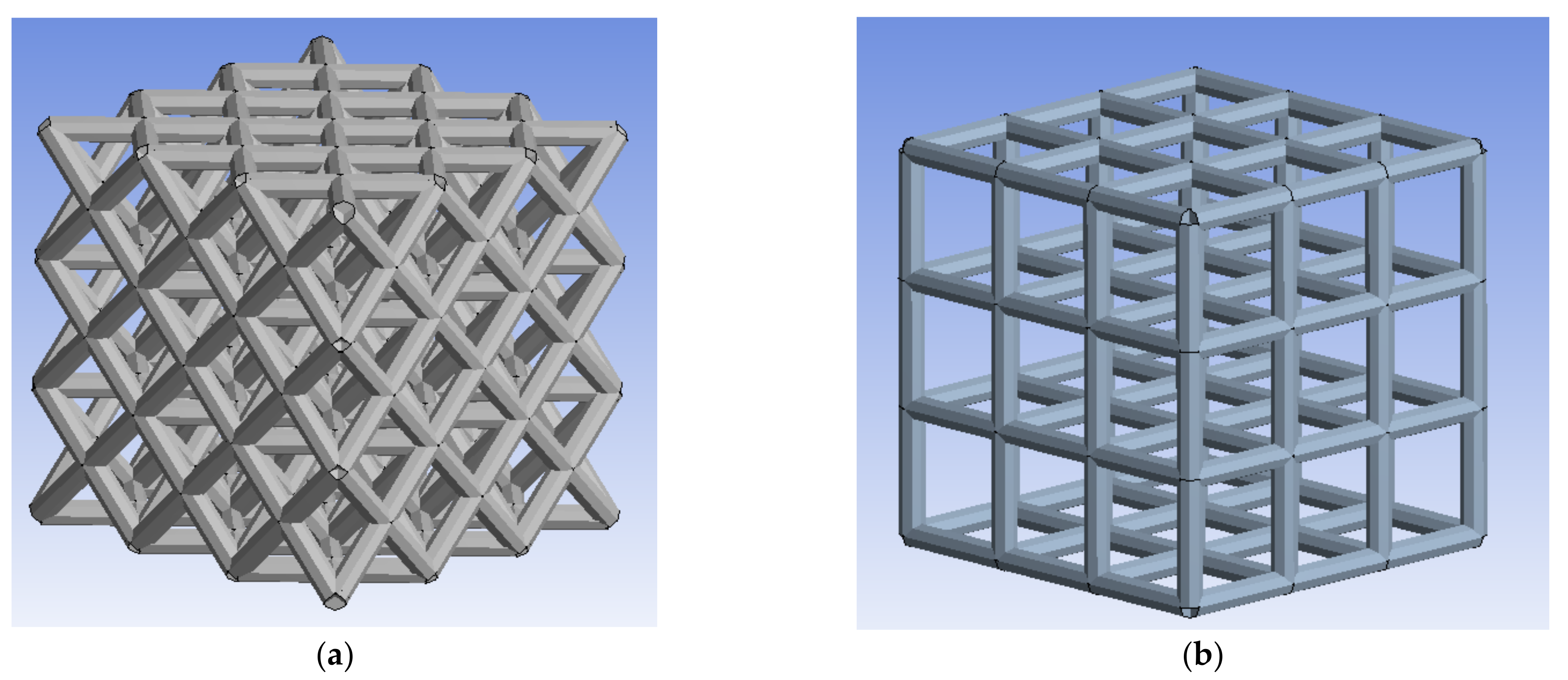
| Unit Cell Type | Pore Size (Micron) | Cell Size (Micron) | Strut Diameter (Micron) |
|---|---|---|---|
| Cubic | 798 | 1444 | 646 |
| Diagonal | 812 | 2616 | 734 |
| Unit Cell Design | Optimized Design (%) | Manufactured Scaffold (%) | |
|---|---|---|---|
| Dry Weighing | Archimedes | ||
| Cubic | 34.47 | 32.97 | 33.77 |
| 33.16 | 33.98 | ||
| 32.91 | 33.85 | ||
| 33.22 | 34.12 | ||
| 32.89 | 33.91 | ||
| 32.08 | 33.04 | ||
| Diagonal | 36.79 | 35.09 | 36.16 |
| 35.02 | 36.10 | ||
| 35.33 | 36.29 | ||
| 34.98 | 35.83 | ||
| 35.26 | 36.21 | ||
| 34.93 | 35.68 | ||
Publisher’s Note: MDPI stays neutral with regard to jurisdictional claims in published maps and institutional affiliations. |
© 2022 by the authors. Licensee MDPI, Basel, Switzerland. This article is an open access article distributed under the terms and conditions of the Creative Commons Attribution (CC BY) license (https://creativecommons.org/licenses/by/4.0/).
Share and Cite
Al-Barqawi, M.O.; Church, B.; Thevamaran, M.; Thoma, D.J.; Rahman, A. Design and Validation of Additively Manufactured Metallic Cellular Scaffold Structures for Bone Tissue Engineering. Materials 2022, 15, 3310. https://0-doi-org.brum.beds.ac.uk/10.3390/ma15093310
Al-Barqawi MO, Church B, Thevamaran M, Thoma DJ, Rahman A. Design and Validation of Additively Manufactured Metallic Cellular Scaffold Structures for Bone Tissue Engineering. Materials. 2022; 15(9):3310. https://0-doi-org.brum.beds.ac.uk/10.3390/ma15093310
Chicago/Turabian StyleAl-Barqawi, Mohammad O., Benjamin Church, Mythili Thevamaran, Dan J. Thoma, and Adeeb Rahman. 2022. "Design and Validation of Additively Manufactured Metallic Cellular Scaffold Structures for Bone Tissue Engineering" Materials 15, no. 9: 3310. https://0-doi-org.brum.beds.ac.uk/10.3390/ma15093310