
The Use of Electrode Tools Obtained by Selective Laser Melting to Create Textured Surfaces

Department of Mechanical Engineering, Perm National Research Polytechnic University, 614000 Perm, Russia
*
Author to whom correspondence should be addressed.
Materials 2022, 15(14), 4885; https://0-doi-org.brum.beds.ac.uk/10.3390/ma15144885
Submission received: 17 June 2022
/
Revised: 7 July 2022
/
Accepted: 11 July 2022
/
Published: 13 July 2022
(This article belongs to the Special Issue Surface Processing of Steels: Materials, Techniques and Applications)
Abstract
:The study and development of the technological foundations for creating a textured surface using an electrode tool obtained by the method of additive manufacturing are the purpose of the work. Methods for obtaining textured surfaces and for creating a tool electrode for electrical discharge machining are considered in this work. The modeling of the electrodetool, analysis of internal stresses during its manufacture by the selective laser melting method, and the manufacture of electrodes are considered. A Realizer SLM 50 laser machine was used to create the electrode tool. Ti6Al4V metal powder with an average particle size of 30 µm was chosen as the material for manufacturing. The experiments were carried out on a copy-piercing electrical discharge Smart CNC machine. The material of the workpiece is corrosion-resistant, heat-resistant, high-alloy steel 15Cr12H2MoWVNNB. An Olympus GX 51 light microscope (Olympus Corporation, Shinjuku-ku, Japan) at 100× magnification was used to visually evaluate the texturing results and measure dimensions. The possibility of using electrodes obtained by the selective laser melting method for texturing surfaces was studied.
1. Introduction
An urgent task of mechanical engineering is to improve the quality of manufacturing high-precision and critical parts with an applied textured profile. The complex profile of parts and the use of modern structural materials with improved physical and mechanical properties do not allow the full use of traditional processing methods.
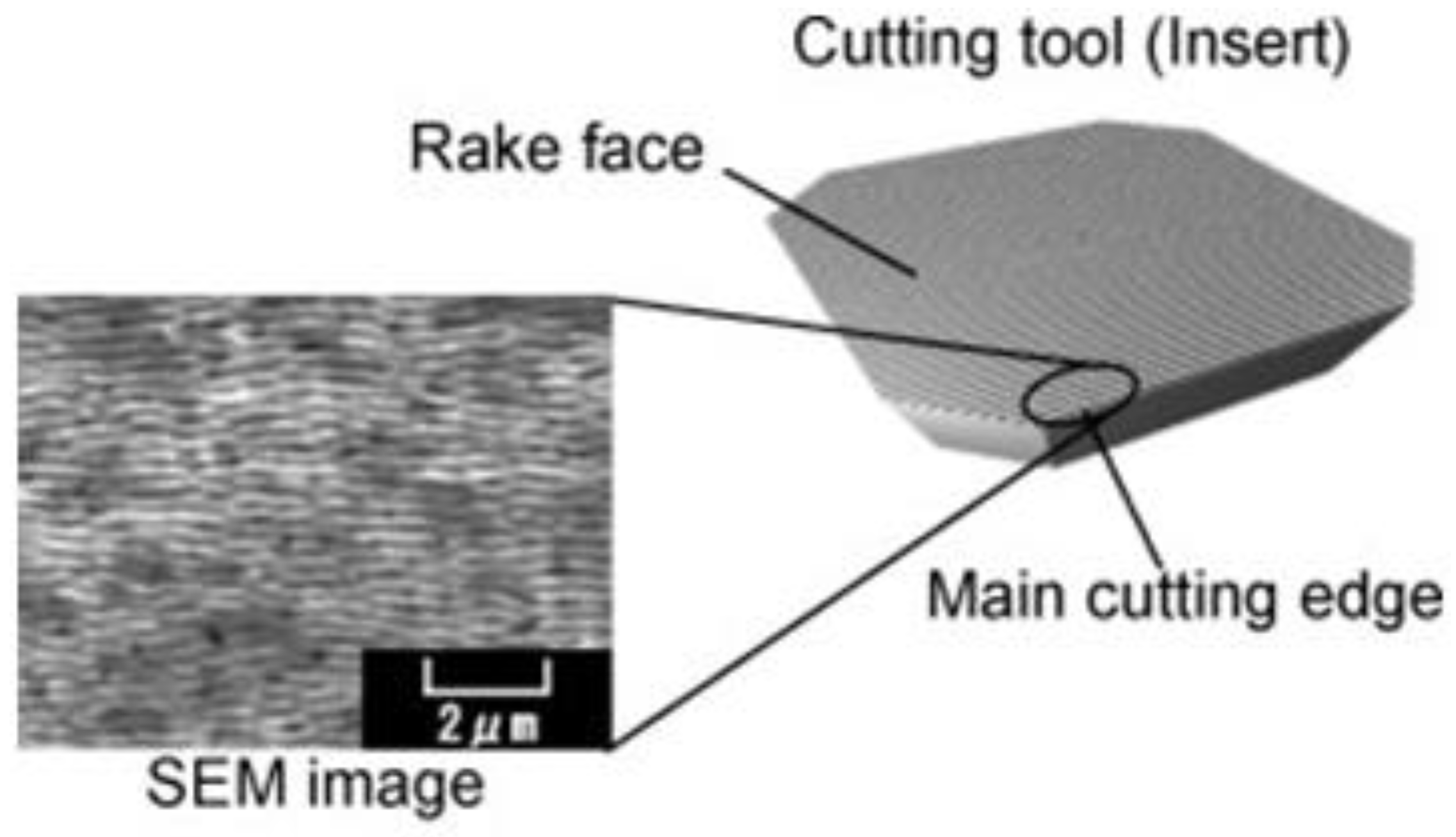
In works [1,2,3,4,5,6], it was noted that in order to improve the operational characteristics of the working surfaces of products, for example, working in conditions of increased friction, it is necessary to apply a textured relief. A textured relief is applied to individual surfaces requiring certain properties. Surface texturing is a method of surface functionalization widely used throughout the world. This is used in various fields: medical implants, wettability tuning, optical properties, hybrid bonding, bond enhancement, or cutting tools [1,2,3,4]. The most common patterns of textured surfaces are dimples, lines (parallel and hatching), square, conical, rhombic, wavy texture, and annular (bulge and smooth corrugation) [3,4]. Surface microtexturing is widely used to improve the tribological properties of cutting tools, such as improving frictional performance and wear protection. The types of patterns produced on the surfaces of the cutting tool were most commonly microgrooves, microholes, microstrip grooves, and microgrooves. In the works [1,2,3,4,5], the influence of polycrystalline diamond tools with microgrooves, made using a fiber laser, was studied (Figure 1).
Textured surfaces are widely used in mechanical engineering. Theyare used to create finished products and mold dies and when creating a special auxiliary element in the form of oil-retaining surfaces in highly loaded friction pairs. The quality and reliability of the entire mechanism depend on the accuracy of applying the textured surface to the working surfaces of the products. It was noted in [5,6] that the application of a textured relief can improve the strength properties of products due to the creation of a fine-grained structure on the surface layer. In addition, the coefficient of friction is reduced by obtaining microstructured oil-retaining cavities. The shape and depth of the resulting pattern and complex relief are the main requirements for creating oil-retaining grooves on the surface of products [1,2,3,4].
The technological process of applying a special pattern to the surface of a precision part using the blade method is expensive and technologically inefficient. A special tool is used to create a complex profile. This tool has high wear during machining. High temperatures occur in the cutting zone. These factors lead to an increase in the cost of manufacturing a part and the frequent occurrence of defects in the production process.
Electrical discharge machining (EDM) technology is used to eliminate possible losses and improve the surface quality. This technology makes it possible to obtain the required surface profile without significant distortion.
The manufacture of an electrode tool (ET) is a limiting factor in the development of EDM technology. ETs made of copper, brass, bronze, and other nonferrous alloys are widely used in EDM. However, obtaining a complex profile on the ET surface is an economically inefficient process and an expensive process. This is due to the high cost and labor intensity of the technology. Most of the metal goes into chips during the manufacture of electrodes from these materials, which makes the process of their manufacture economically unprofitable [1].
A high pace of development of digital technologies in mechanical engineering is currently observed. Additive technologies are widely used in the creation of fixtures, dies, and tools. Their development is due to the fact that high quality requirements are imposed on finished products [1,2,3,4,5].
Selective laser melting (SLM) technology is one of the ways to obtain ETs. This consists of layer-by-layer melting of the metal powder to obtain the finished product [7,8,9,10]. This method makes it possible to obtain ETs practically without the use of mechanical operations. These operations are necessary in order to extract the constructed part from the substrate on which it is grown, and it is also possible to finish the surface with ETs by grinding [11,12].
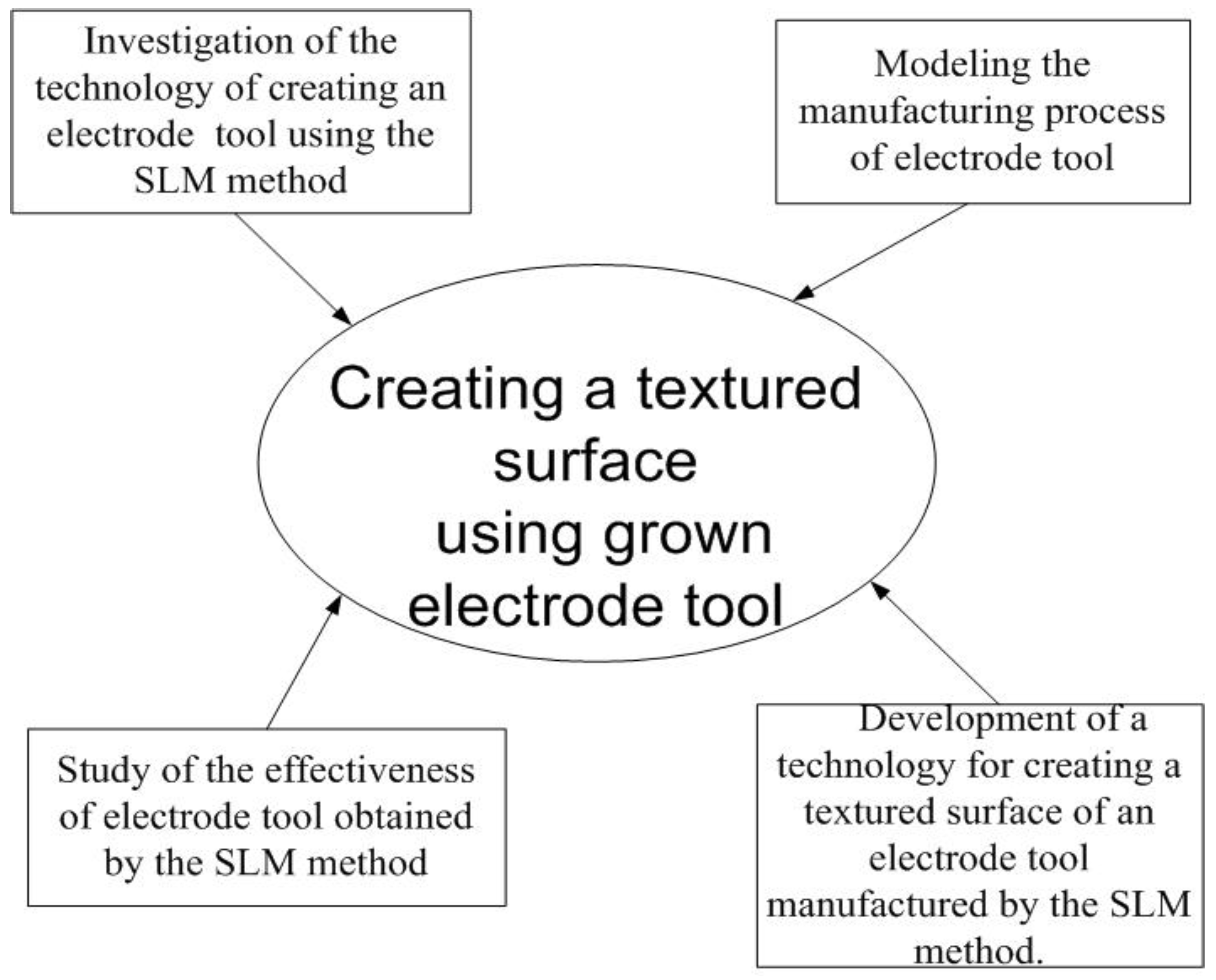
The performance of the EDM ET and the applicability of the ET produced by the selective laser melting method for EDM have not been fully studied [13,14,15,16,17,18]. The development of EDM technology by grown ETs obtained by the SLM method for applying a textured surface is relevant [19,20] (Figure 2).
The study and development of the technological foundations for creating a textured surface using an electrode tool obtained by the method of additive manufacturing are the purpose of the work.
2. Materials and Methods
A Realizer SLM-50 laser machine was used to create ETs. The size of the zone for constructions was Ø70 × 35 mm. A pressure of 8 mbar was maintained in the working chamber. Argon was used as a protective atmosphere. A fiber laser was used in the process, with a power of 50 W and a wavelength of 680 nm. Titanium powder particles were sintered on a titanium substrate. The thickness of the treated layer was 30 μm.The metal powder Ti6Al4V Starbond Ti4 Powder 45, S&S Scheftner GmbH, Mainz, Germany, with an average particle size of 30 µm and a shape close to a sphere was chosen as the material for manufacturing.
The experiments were carried out on a copy-piercing electroerosive Smart CNC machine (Electronica India Limited, West Bengal, India). The material of the workpiece is corrosion-resistant, heat-resistant, high-alloy steel 15Cr12H2MoWVNNB. Mechanical processing (grinding) of the working end was carried out after removing the ET from the substrate in order to remove the supports.
Processing modes are presented in Table 1.
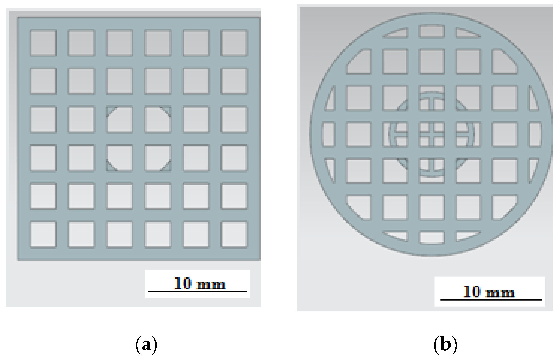
Processing was carried out in the machine tank filled with transformer oil. An Olympus GX 51 light microscope at 100× magnification was used to visually evaluate texturing results andto measure dimensions. Theoretical modeling was carried out using Siemens NX v.11, Materialize Magics v.22, and ANSYS Additive software 2019. The ETwas modeled in two types:ET with a square section and a side measuring 19 mm (Figure 3a) and a cylindrical ET with a diameter of 19 mm (Figure 3b). The end surface of both electrodes was made in the form of square cells with a cell size of 2 mm and a partition thickness of 1 mm. The height of the working surface of the ETwas 3 mm.
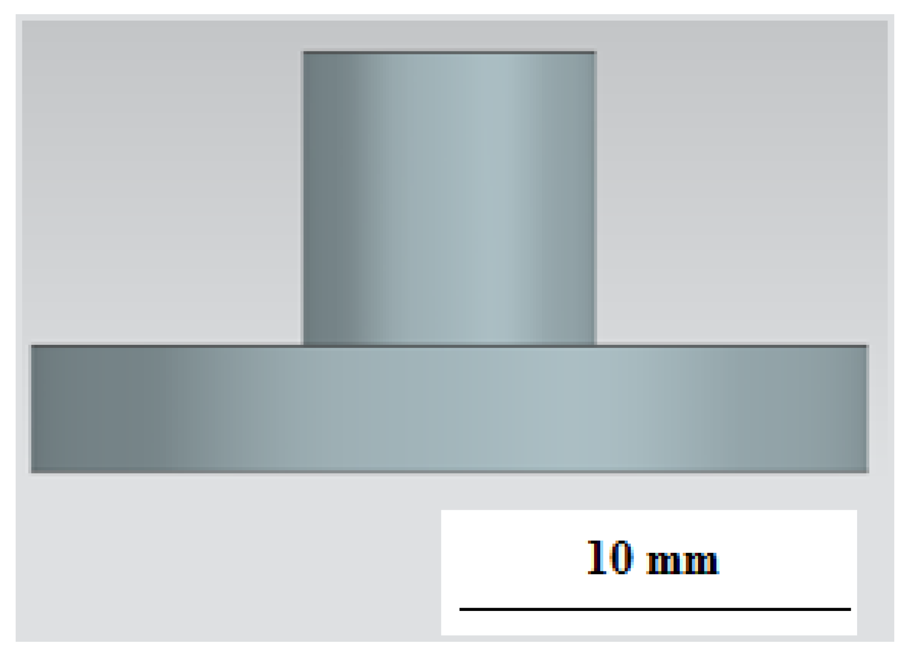
A 7 × 10 mm cylinder was provided for fixing the electrode in the electrode holder (Figure 4).
The process of preparing a 3D model for manufacturing included the following steps:
- Setting the working space of the installation in the CAD system (Siemens NX v.11) and placing the required number of elements on the platform;
- Construction of supports;
- Modeling the construction process in ANSYSAdditive;
- Correction of the model and supports (if necessary);
- Construction of the part.
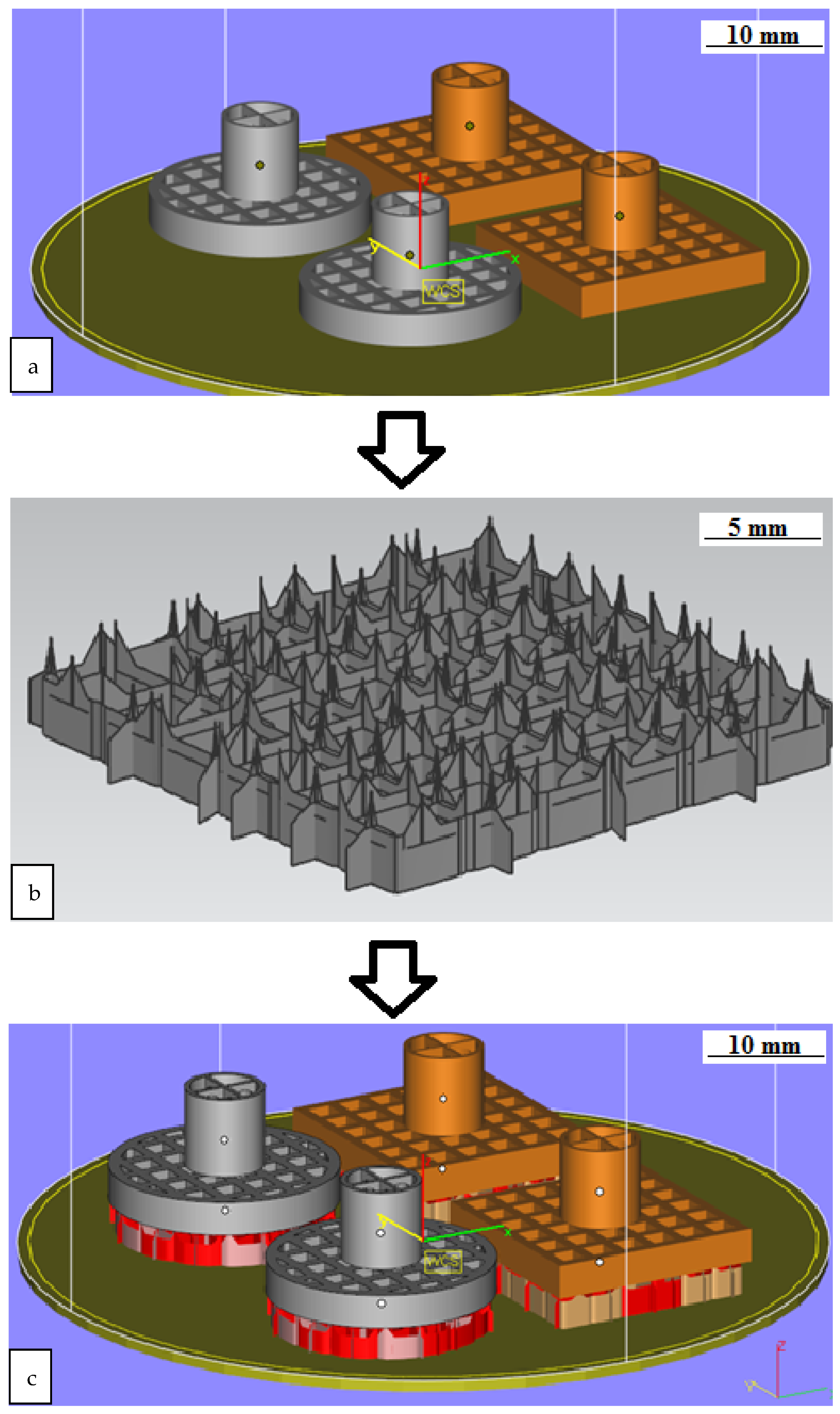
The preparation of the model for manufacturing was carried out in the Materialize Magics environment. A cylinder with dimensions of 70 × 40 mm was the working space of the installation for making a model (Figure 5a).This allowed to reduce the time and reduce the cost of manufacturing. Supports were created in the minimum volume. This volume was sufficient to hold the grown product. (Figure 5b). The support type was a block. The support material entered the main part to a depth of 0.1–0.2 mm for reliable fastening of the part to the supports (Figure 5c).
After designing the supports, it was necessary to evaluate the internal stresses. These stresses arose during the construction process. An internal stress analysis was performed in the ANSYS Additive environment.
3. Results
3.1. Simulation of Internal Stresses
The forces arising during the construction process were applied to the part in the process of modeling the additive process. The part was deformed. Creating a preliminary deformation allows you to change the original model. When external loads are applied to solids, the bodies can be deformed up to destruction. The degree of deformation depends on the magnitude of the load. Bodies return to their original shape under small loads after they are removed. Since the deformed bodies are in equilibrium, the external loads must be balanced by internal forces. Deformation leads to a change in the crystal lattice. Inner forces appear. These forces are trying to return the system to its original state. As a result, forces begin to act on each elementary particle of the body. These forces together form the stress vector P.
To determine the stress vector P, it is necessary to introduce the concept of the stress tensor (Formula (1)).
We introduced the stress tensor as follows:
For the element , the first index shows on which site the given stress acts, and the second index shows in which direction. If the indices are the same, then this is a normal stress, and if they are different, it is a shear stress.
If the stress tensor is known, then the stress vector (Formula (2)) can be defined as:
If the stress tensor is determined in a given coordinate system, then, in the future, it is always possible to determine the stress vector (internal forces) acting on any arbitrarily chosen area.
The deformable body, as a whole, will be in equilibrium if the main vector of forces and the main vector of moments of mass and surface forces are equal to zero.
where is radius vector of an arbitrary point;
is force;
is body forces;
ds is elementary section;
dv is elementary volume;
isdensity of the material.
Select an arbitrary region V* defined by the surface S*.
On the surface S*, forces are distributed, which are internal forces for the volume V and external for the volume V*. Therefore, if the internal volume is in equilibrium, then:
From the Ostrogradsky–Gauss formula it follows:
From Formula (10) it follows:
Since V* is an arbitrary volume, equality is possible when
Equation (12) is an equilibrium equation in differential form.
By analogy with Newton’s 2nd law (based on the D’Alembert principle), we can obtain the equation of motion in the form:
Each term in Equation (13) has its own meaning.
is forces of inertia in some elementary volume;
is body forces (body forces);
is internal forces (a term that takes into account internal forces in the body).
The strain tensor is a tensor that characterizes the tension (compression) and change in the shape of each point of the body during deformation.
In a classical continuous medium, in which particles are material points and have only three translational displacements, but no rotation, the strain tensor (the Cauchy–Green tensor) is generally defined as:
where is a vector describing the displacement of a body point.
The third term in the strain tensor (14) makes it possible to correctly take into account complex deformation in the case of large deformations. However, the presence of this term significantly complicates the solution of the problem of mechanics; therefore, in the case of small deformations (ε << 1), this term can be neglected, writing the strain tensor in the form:
The connection between displacements and deformations is called geometric relations.
In the Cartesian coordinate system, geometric relationships can be expressed:
Physical relationships are the relationship between stresses and strains. Many physical relationships are nonlinear dependencies, which are described by differential or integrodifferential equations.
In general, the physical relationships look like:
Generalized Hooke’s law:
The factor includes 81 parameters, but for a linear isotropic material, two characteristics remain: Young’s modulus (E) and Punch’s ratio (ε). For elastic materials, Hook’s law is expressed by Formula (26):
For a linear, isotropic material, Hooke’s law is expressed by (27):
where λ and μ are Lame’s parameters;
is the volumetric strain;
is the Kronecker symbol.
Based on Equations (25) and (27), normal and shear stresses can be determined:
Instead of the Lame’s parameters, other technical parameters (material characteristics) often determined from the experiment can be used.
Further, the temperature deformations and stresses during heating are taken into account. Let the body heat up by ΔT from temperature T1 to T2, i.e.,T2 = T1+ ΔT. Then, the total deformations can be written:
Temperature deformations can be expressed in the form (35):
where α is the linear coefficient of thermal expansion.
Then, elastic deformations can be expressed in the form (36):
where is elastic deformations;
is total deformations (determined from geometric relationships);
is temperature deformations.
If we substitute Equation (36) into Hooke’s law, we obtain:
where .
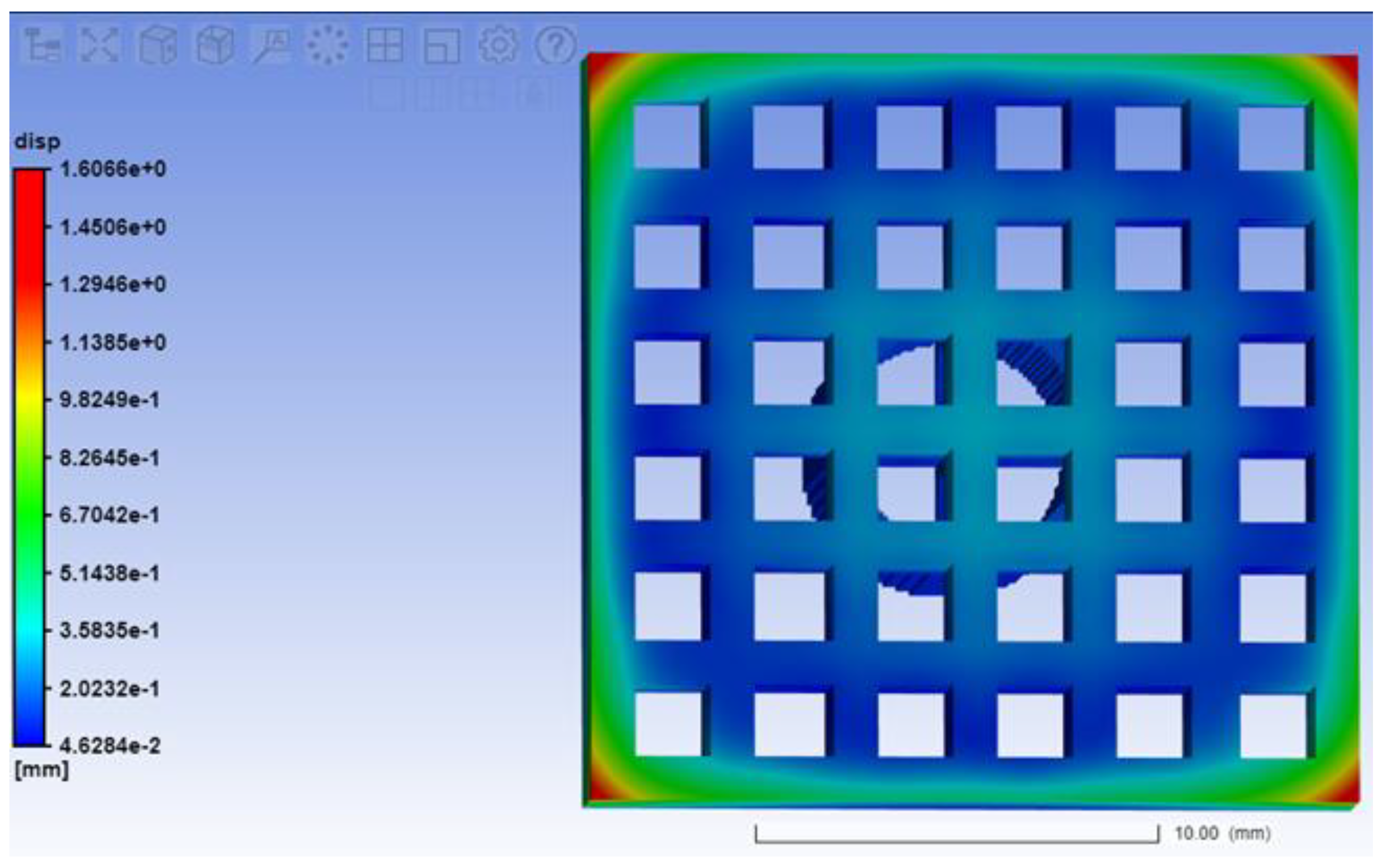
To perform the analysis, we set the parameters of the Ti6Al4V material: modulus of elasticity E = 116 GPa and Poisson’s ratio μ = 0.31. The obtained values of the deformation of the EI are shown in Figure 6.
As a result of calculations for internal stresses when constructing the ET, it was revealed that the largest displacements are observed in the corners of the electrode (1.6 mm) (Figure 6).
3.2. Processing Grown ETs
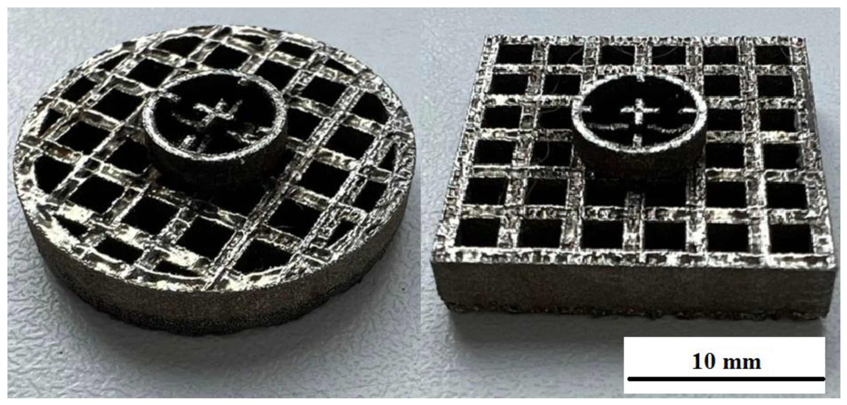
An ET with a square base andan ET with a round base are obtained as a result of modeling and manufacturing using the SLM technology.
The wear of an ET is estimated after processing the surface of the workpiece. This is shown in Table 2. The processing was carried out on a round and square section of the ET on two samples.
It is shown that the round ET showed minimal wear of the ET. The amount of wear with a round ET is more than two times less than when machining with a square ET.
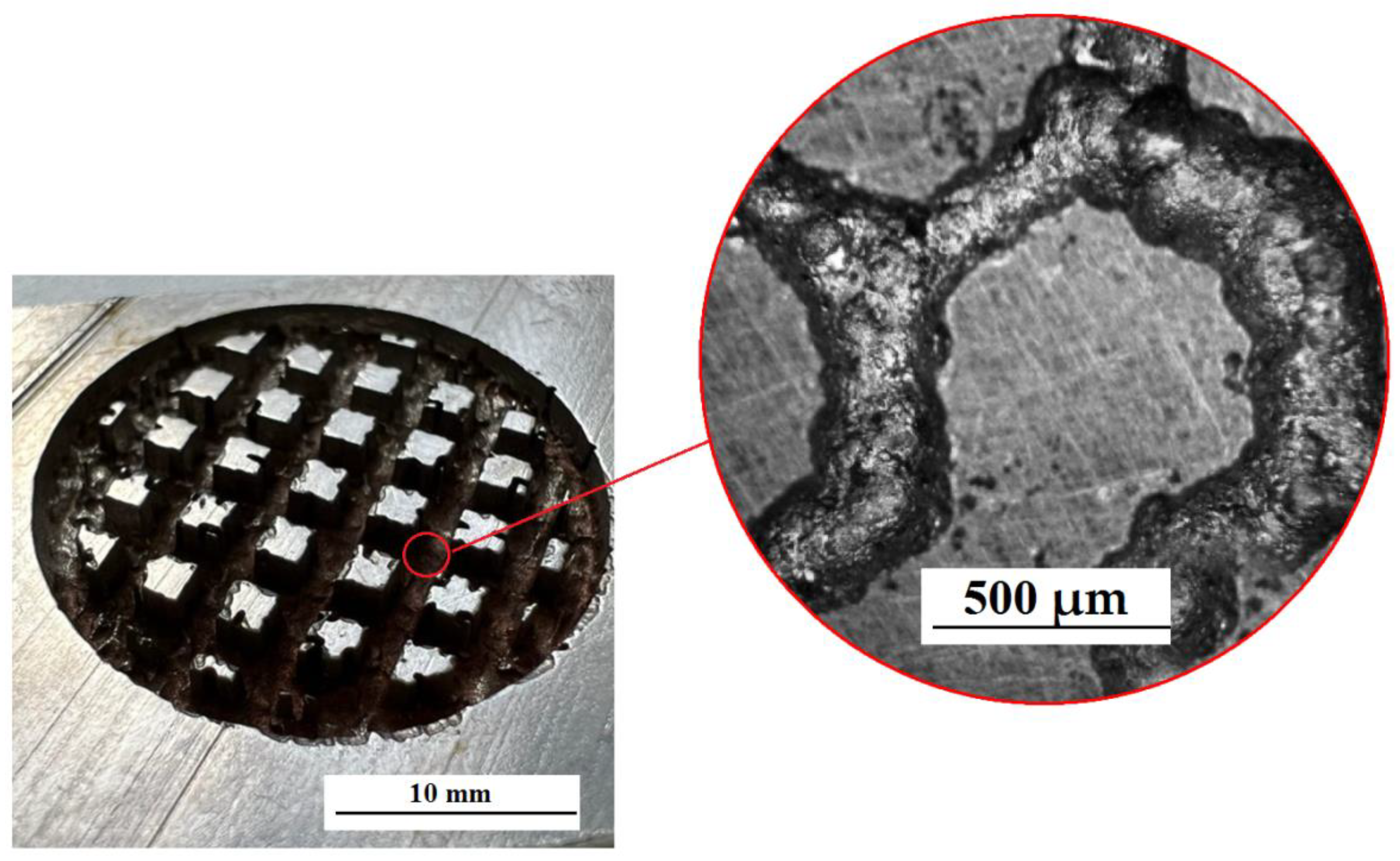
The creation of a special textured pattern on the surface was carried out using a cellular ET with different cell parameters (Figure 7). The relief was formed as a result of processing on the surface of the workpiece. This figure repeats the end surface of the ET [21,22,23,24,25].
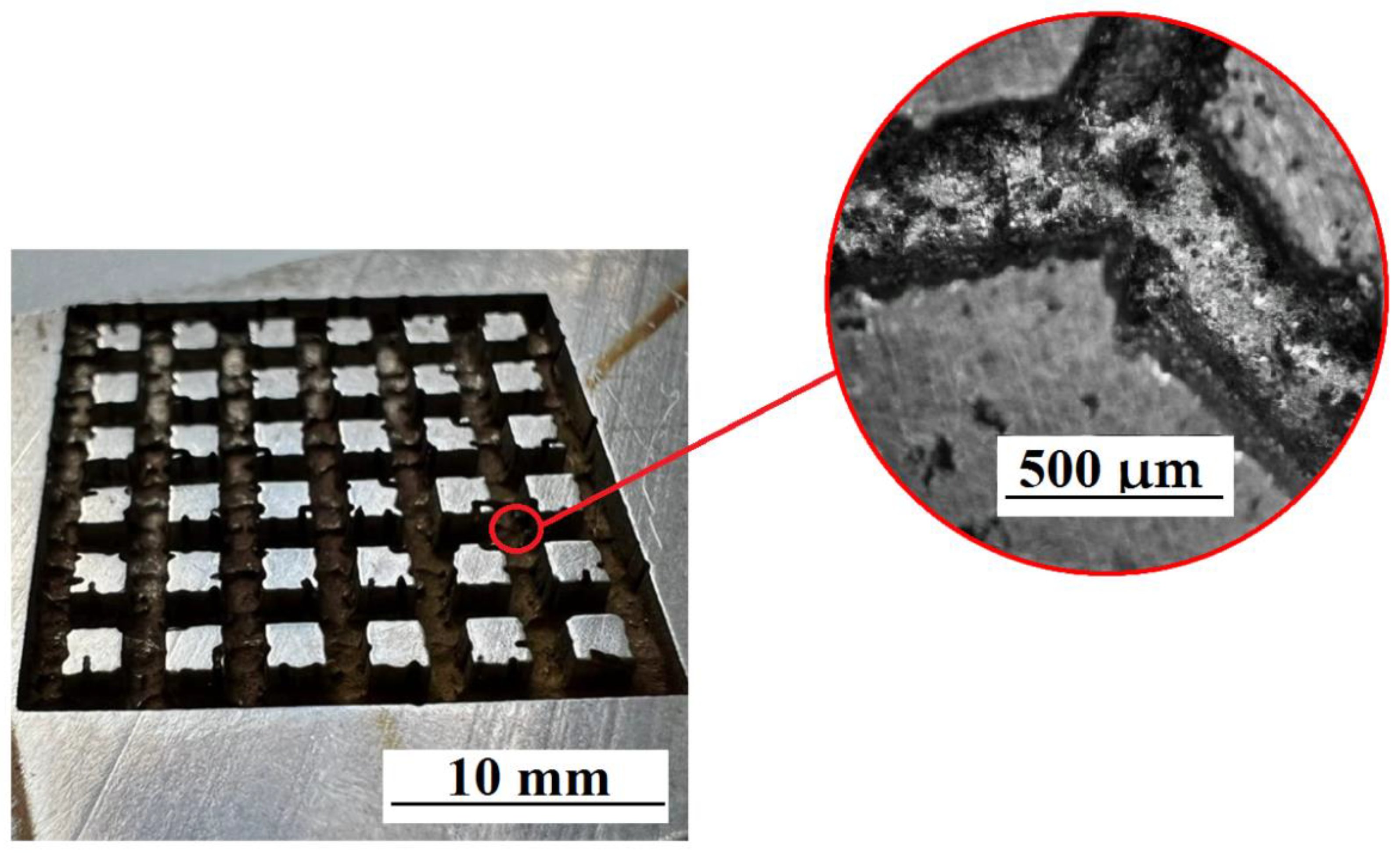
It has been established that the cell profile has a different character (Figure 7 and Figure 8). This is due to the fact that the ET surface is formed by sintering a spherical powder. This powder does not provide 100% surface straightness. This factor indicates uneven processing and the absence of clear patterns in the construction of a textured relief at the microlevel. Figure 7 and Figure 8 shows the machined surfaces of the workpiece at 100× magnification.
Copying of the end face of the ET and traces of powder alloys are observed on the treated surface. Multilevel surface treatment is observed. When processing with a square ET, the size of the textured depressions is greater than when processing with a round ET (Figure 9).
On the basis of the experiment, it was shown that a textured surface with complex macrogeometry and microgeometry on a machined workpiece was created using the grown EE (SLM method). The presence of convex surfaces of fused powder material on the ET surface made it possible to form a textured system of multimodal roughness on the treated surface. The formation of tested surfaces by the EDM method using the grown ETon products operating under frictional interaction conditions increases their oiliness and, accordingly, hydrophobicity.
4. Conclusions
The use of ET 3D printing methods has expanded the possibilities of electrical discharge machining. It becomes possible to create ETs for surface texturing. This is an important and separate direction for the development of EDM. This paper shows an important point using the example of oil-retaining grooves. It is shown that SLM electrodes make it possible to make not only a macrorelief, but also a microrelief of a textured surface.
- A study of the technology for creating ETs by the SLM method for EDM was carried out. The use of additive technologies makes it possible to manufacture a complex-profile ET with the required end surface topography.
- Simulation of the ET manufacturing process was carried out. A model that allows describing the manufacturing process and assessing the internal stresses that occur during construction, as well as a possible change in the shape and dimensions of the finished part, was obtained in the work. It has been established that during the manufacturing process of the part, the greatest internal stresses occur in the corners of the ET. These values allow us to make adjustments to the frequency of supports for additional fastening of the part to the machine substrate.
- The technology for creating a textured surface of the ET produced by the SLM method was developed. The creation of oil-retaining grooves on the surface of a product using EDM has a great practical application in mechanical engineering. As a result of technology development, oil-retaining grooves were created on the parts of the friction pair. These grooves improve the performance properties of the product.
Author Contributions
Conceptualization, E.S.S. and T.R.A.; methodology, K.R.M. and T.R.A.; validation, T.R.A.; formal analysis, T.R.A. and E.S.S.; investigation, E.S.S. and T.R.A.; resources, E.S.S., T.R.A. and K.R.M.; data curation, E.S.S. and K.R.M.; writing—original draft preparation, E.S.S. and T.R.A.; writing—review and editing, K.R.M. and T.R.A.; visualization, T.R.A.; supervision, T.R.A.; project administration, K.R.M. and T.R.A. funding acquisition, T.R.A., E.S.S. and K.R.M. All authors have read and agreed to the published version of the manuscript.
Funding
The authors gratefully acknowledge financial support under the Mega-grants program, contract no. 075-15-2021-578 of 31 May 2021, hosted by Perm National Research Polytechnic University.
Institutional Review Board Statement
Not applicable.
Informed Consent Statement
Not applicable.
Data Availability Statement
Not applicable.
Conflicts of Interest
The authors declare no conflict of interest. The funders had no role in the design of the study; in the collection, analyses, or interpretation of data; in the writing of the manuscript, or in the decision to publish the results.
References
- Popov, V.; Lobanov, M.; Stepanov, S.; Qi, Y.; Muller-Kamskii, G.; Popova, E.; Katz-Demyanetz, A.; Popov, A. Texturing and Phase Evolution in Ti-6Al-4V: Effect of Electron Beam Melting Process, Powder Re-Using, and HIP Treatment. Materials 2021, 14, 4473. [Google Scholar] [CrossRef] [PubMed]
- Zeidler, H.; Aliyev, R.; Gindorf, F. Efficient Finishing of Laser Beam Melting Additive Manufactured Parts. J. Manuf. Mater. Process. 2021, 5, 106. [Google Scholar] [CrossRef]
- Moldovan, E.R.; Doria, C.C.; Ocaña, J.L.; Istrate, B.; Cimpoesu, N.; Baltes, L.S.; Stanciu, E.M.; Croitoru, C.; Pascu, A.; Munteanu, C.; et al. Morphological Analysis of Laser Surface Texturing Effect on AISI 430 Stainless Steel. Materials 2022, 15, 4580. [Google Scholar] [CrossRef] [PubMed]
- Quintanilla-Correa, D.I.; Peña-Parás, L.; Maldonado-Cortés, D.; Rodriguez-Villalobos, M.C.; Hernández-Rodríguez, M.A.L. State of the art of surface texturing forbiotribologyapplications. Int. J. Adv. Manuf. Technol. 2021, 13, 143–150. [Google Scholar] [CrossRef]
- Pisarciuc, C. A review of unconventional procedures for manufacturing tool electrodes used in EDM. Rom. Recent 2014, 15, 205–209. [Google Scholar]
- Kremlev, S.; Lesnikov, R.; Alikin, E.; Ablyaz, T. Experimental study of electrical discharge machining of highly porous cellular materials. Mod. Probl. Sci. Education. 2014, 6, 109. [Google Scholar]
- Gu, L.; Farhadi, A.; Zhu, Y.; He, G.; Zhao, W.; Rajurkar, K. A novel tool design procedure for arc sweep machining technology. Mater. Manuf. Process. 2020, 35, 113–121. [Google Scholar] [CrossRef]
- Dürr, H.; Pilz, R.; Eleser, N.S. Rapid tooling of EDM electrodes by means of selective laser sintering. Comput. Ind. 1999, 39, 35–45. [Google Scholar] [CrossRef]
- Kechagias, J.; Iakovakis, V.; Katsanos, M.; Maropoulos, S. EDM electrodes manufacturing using rapid tooling concept. Int. J. Eng. Res. Development. 2012, 3, 58–70. [Google Scholar] [CrossRef]
- Uhlmann, E.; Bergmann, A.; Bolz, R. Manufacturing of carbide tools by Selective Laser Melting. Procedia Manuf. 2018, 21, 765–773. [Google Scholar] [CrossRef]
- Zhang, R.; Zhang, Y.; Liu, Y.; Shen, Y.; Li, Z.; Wang, X. Energy distribution and material removal of electric arc machining (EAM). J. Mater. Process. Technol. 2016, 242, 110–116. [Google Scholar] [CrossRef]
- Shen, Y.; Liu, Y.; Zhang, Y.; Dong, H.; Sun, P.; Wang, X.; Zheng, C.; Ji, R. Effects of an Electrode Material on a Novel Compound Machining of Inconel718. Mater. Manuf. Process. 2015, 31, 845–851. [Google Scholar] [CrossRef]
- Xu, H.; Gu, L.; Zhao, W.; Chen, J.; Zhang, F. Influence of flushing holes on the machining performance of blasting erosion arc machining. Proc. Inst. Mech. Eng. Part B J. Eng. Manuf. 2015, 231, 1949–1960. [Google Scholar] [CrossRef]
- Zhou, J.P.; Liang, C.H.; Teng, W.J.; Xu, Y.; Zhou, B.S. Study on Rules in Material Removal Rate and Surface Quality of Short Electric Arc Machining Process. Adv. Mater. Res. 2008, 33, 1313–1318. [Google Scholar] [CrossRef]
- Verleysen, K.; Coppitters, D.; Parente, A.; De Paepe, W.; Contino, F. How can power-to-ammonia be robust? Optimization of an ammonia synthesis plant powered by a wind turbine considering operational uncertainties. Fuel 2020, 266, 117049. [Google Scholar] [CrossRef]
- Chen, J.; Gu, L.; Xu, H.; Zhao, W. Study on blasting erosion arc machining of Ti–6Al–4V alloy. Int. J. Adv. Manuf. Technol. 2015, 85, 2819–2829. [Google Scholar] [CrossRef]
- Zhu, Y.; Gu, L.; Farhadi, A.; He, G.; Zhao, W. Observation and Analyzation of Plasma Channel Evolution Behavior in Air Flushing Electrical Arc Machining process. Adv. Mater. Technol. 2018, 100, 3127–3138. [Google Scholar] [CrossRef]
- Zhang, F.; Gu, L.; Chen, J.; Xu, H.; Zhao, W. Observation and modeling research of high-velocity flushing effect on the performance of BEAM. Int. J. Adv. Manuf. Technol. 2015, 86, 935–942. [Google Scholar] [CrossRef]
- Meshcheriakov, G.; Nosulenko, V.; Bokov, V. Physical and Technological Control of Arc Dimensional Machining. CIRP Ann. 1988, 37, 209–212. [Google Scholar] [CrossRef]
- Świercz, R.; Oniszczuk-Świercz, D. Investigation of the Influence of Reduced Graphene Oxide Flakes in the Dielectric on Surface Characteristics and Material Removal Rate in EDM. Materials 2019, 12, 943. [Google Scholar] [CrossRef] [Green Version]
- Zhu, G.; Zhang, Q.; Wang, H.; Wang, K.; Zhang, M. Machining behaviors of short electrical arc milling with high frequency and high voltage pulses. Int. J. Adv. Manuf. Technol. 2016, 90, 1067–1074. [Google Scholar] [CrossRef]
- Lonardo, P.; Bruzzone, A. Effect of Flushing and Electrode Material on Die Sinking EDM. CIRP Ann. 1999, 48, 123–126. [Google Scholar] [CrossRef]
- Wong, Y.; Lim, L.; Lee, L. Effects of flushing on electro-discharge machined surfaces. J. Mater. Process. Technol. 1995, 48, 299–305. [Google Scholar] [CrossRef]
- Farhadi, A.; Zhu, Y.; Gu, L.; Zhao, W. Electric arc sweep milling of open channels. Int. J. Adv. Manuf. Technol. 2019, 102, 673–683. [Google Scholar] [CrossRef]
- Li, L.; Gu, L.; Xi, X.; Zhao, W. Influence of flushing on performance of EDM with bunched electrode. Int. J. Adv. Manuf. Technol. 2011, 58, 187–194. [Google Scholar] [CrossRef]
Figure 1.
Surface of a textured cutting tool.

Figure 2.
Stages of creating a textured surface using the grown ET.

Figure 3.
Three-dimensionalmodel of the electrode tool: (a) square ET and (b) round ET.

Figure 4.
ET model (side view).

Figure 5.
ETmodeling: (a) Materialize Magics workspace with placement of models for manufacturing; (b) supports for square ET; (c) arrangement of models on supports in the working space of the installation.
Figure 5.
ETmodeling: (a) Materialize Magics workspace with placement of models for manufacturing; (b) supports for square ET; (c) arrangement of models on supports in the working space of the installation.

Figure 6.
Deformation of the ET after separation from the supports.

Figure 7.
ET manufactured using SLM technology.

Figure 8.
ET with a square section.

Figure 9.
Treated surface ET with a circular cross section.


Table 1.
Processing mode.
| Pulse on time (Ton), µs | 100 |
| Current (I), A | 4 |
| Voltage (U), V | 50 |
| Depth of processing, mm | 2 |
Table 2.
The amount of wear of an ET.
| Electrode No. | Average Height of the Working Part of the Electrode mm | Wear Rate, % | |
|---|---|---|---|
| New | After Processing | ||
| 1 (round) | 35,795 | 35,723 | 0.2 |
| 2 (square) | 35,202 | 35,026 | 0.5 |
Publisher’s Note: MDPI stays neutral with regard to jurisdictional claims in published maps and institutional affiliations. |
© 2022 by the authors. Licensee MDPI, Basel, Switzerland. This article is an open access article distributed under the terms and conditions of the Creative Commons Attribution (CC BY) license (https://creativecommons.org/licenses/by/4.0/).
Share and Cite
MDPI and ACS Style
Ablyaz, T.R.; Shlykov, E.S.; Muratov, K.R. The Use of Electrode Tools Obtained by Selective Laser Melting to Create Textured Surfaces. Materials 2022, 15, 4885. https://0-doi-org.brum.beds.ac.uk/10.3390/ma15144885
AMA Style
Ablyaz TR, Shlykov ES, Muratov KR. The Use of Electrode Tools Obtained by Selective Laser Melting to Create Textured Surfaces. Materials. 2022; 15(14):4885. https://0-doi-org.brum.beds.ac.uk/10.3390/ma15144885
Chicago/Turabian StyleAblyaz, Timur Rizovich, Evgeny Sergeevich Shlykov, and Karim Ravilevich Muratov. 2022. "The Use of Electrode Tools Obtained by Selective Laser Melting to Create Textured Surfaces" Materials 15, no. 14: 4885. https://0-doi-org.brum.beds.ac.uk/10.3390/ma15144885
Note that from the first issue of 2016, this journal uses article numbers instead of page numbers. See further details here.