
Punching Shear Behavior of Slabs Made from Different Types of Concrete Internally Reinforced with SHCC-Filled Steel Tubes
 and
and
Abstract
:1. Introduction
2. Experimental Program
2.1. General Description
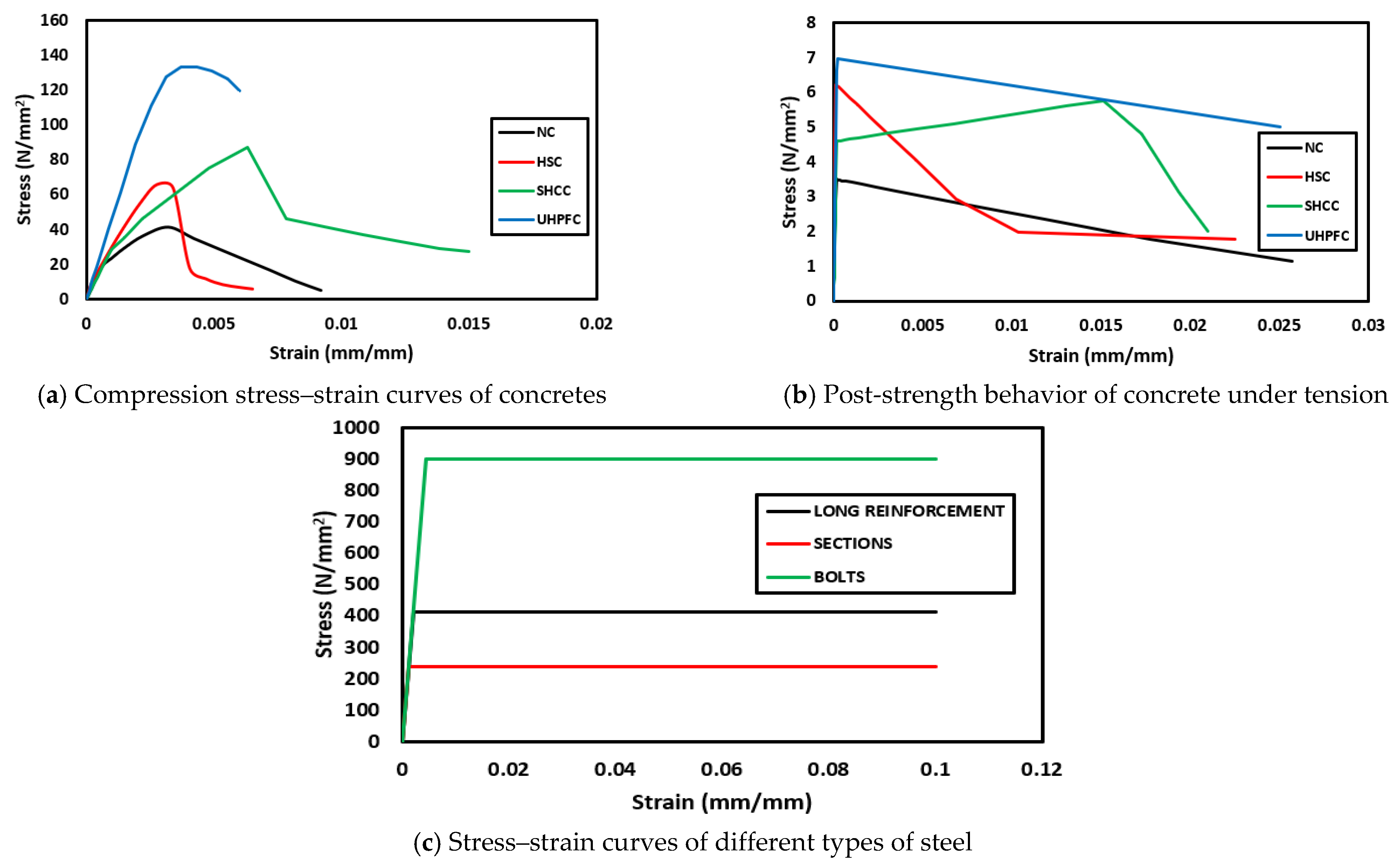
2.2. Material Properties
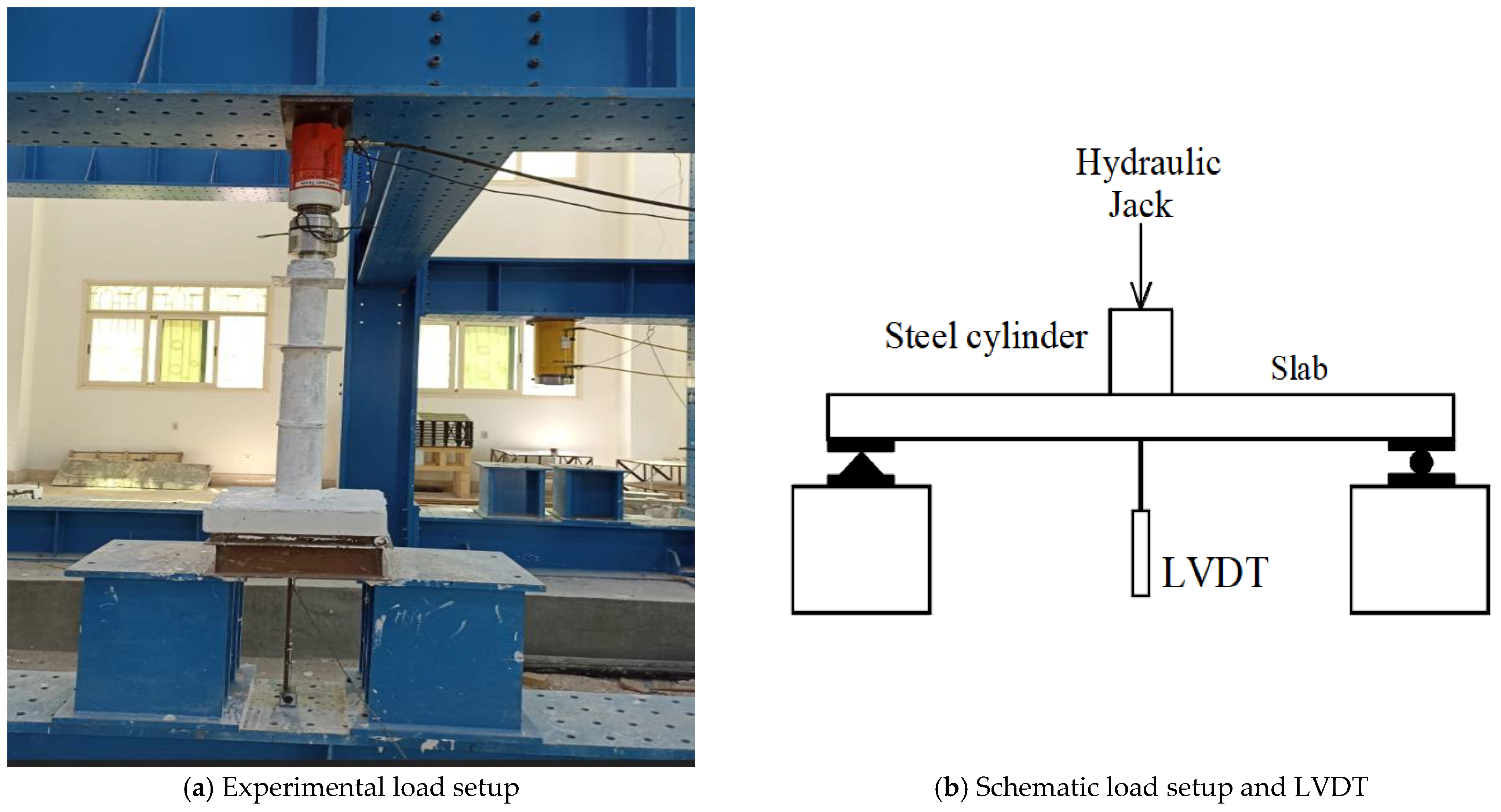
3. Test Setup and Instrumentation
4. Results and Discussion
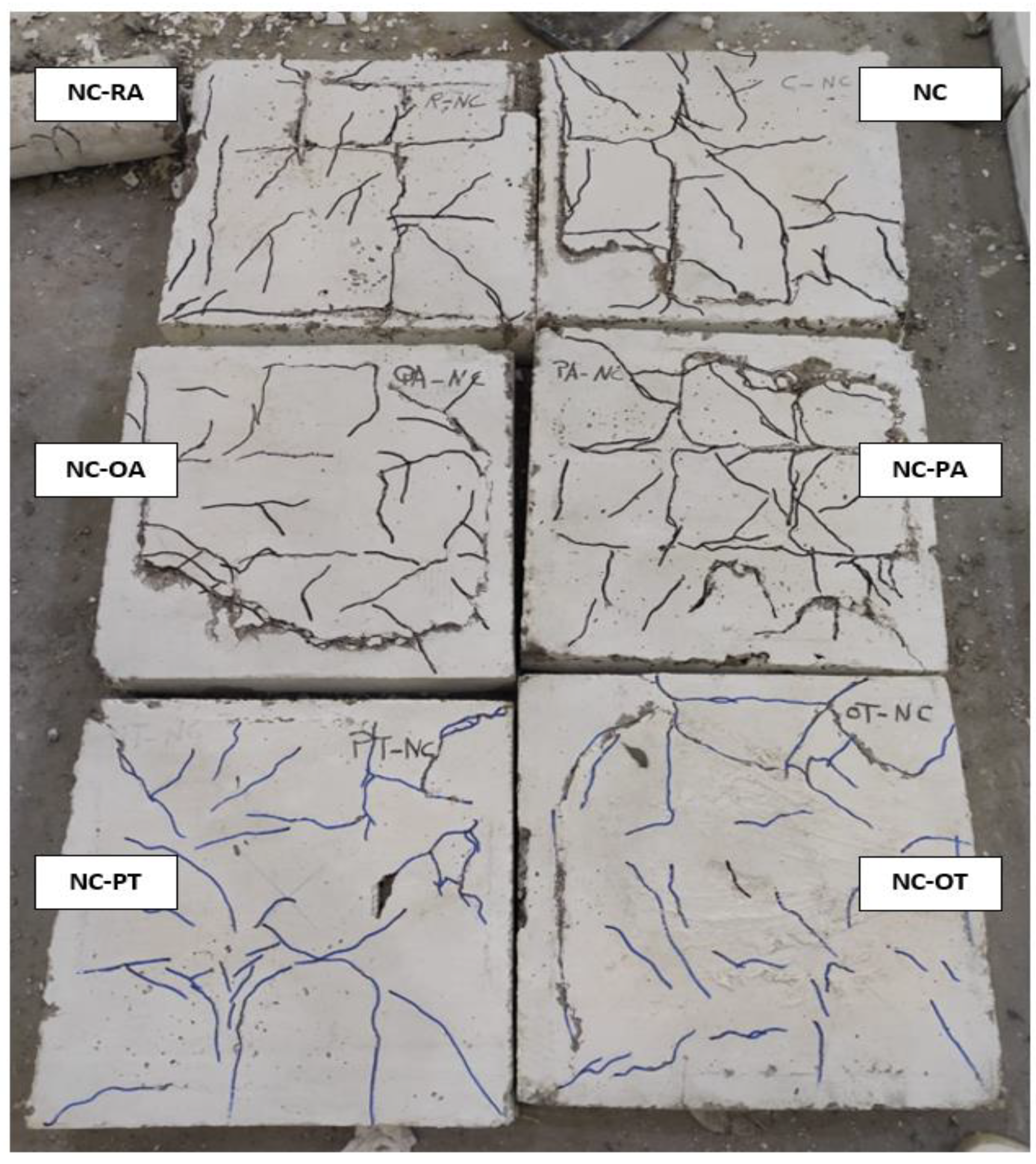
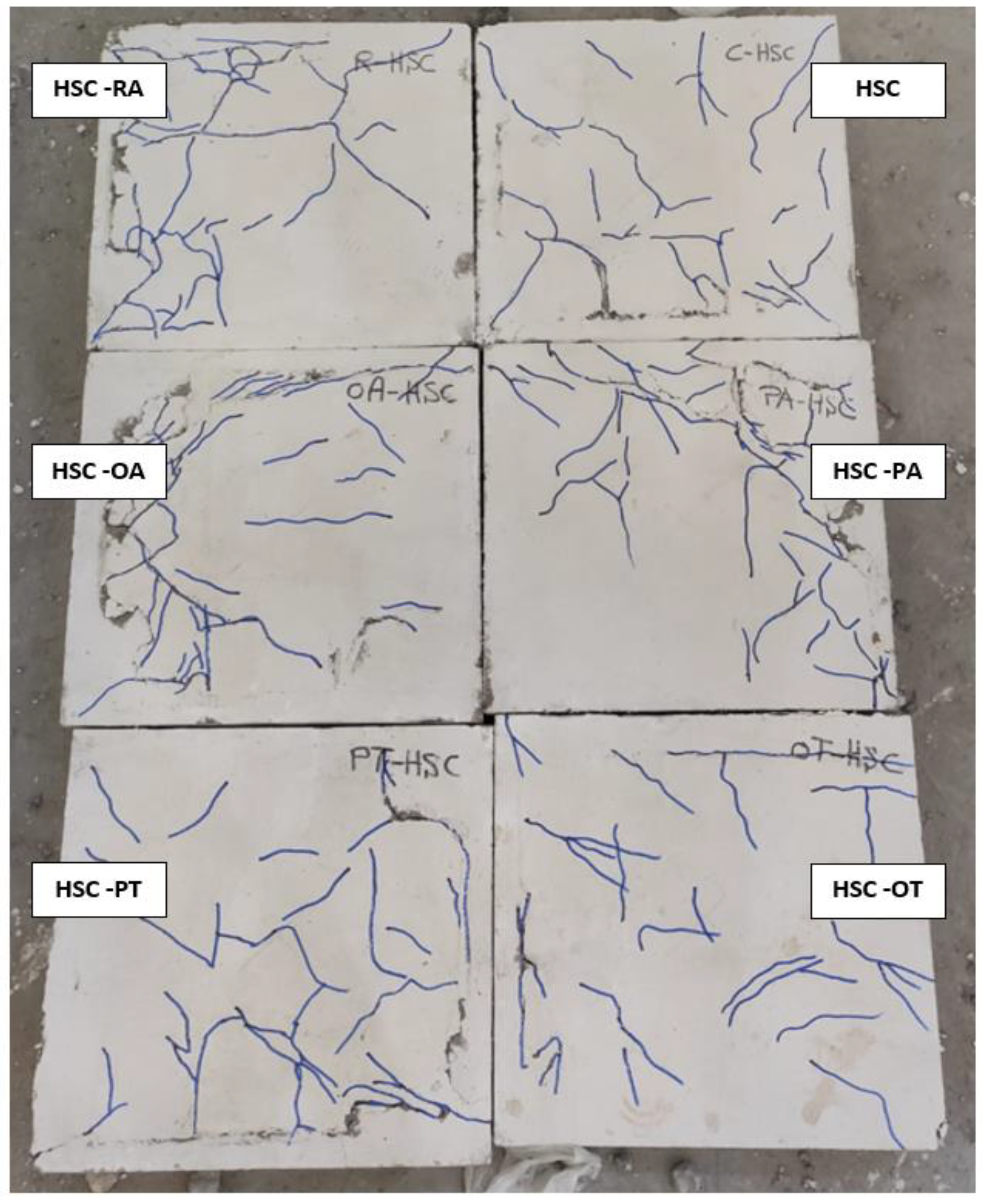
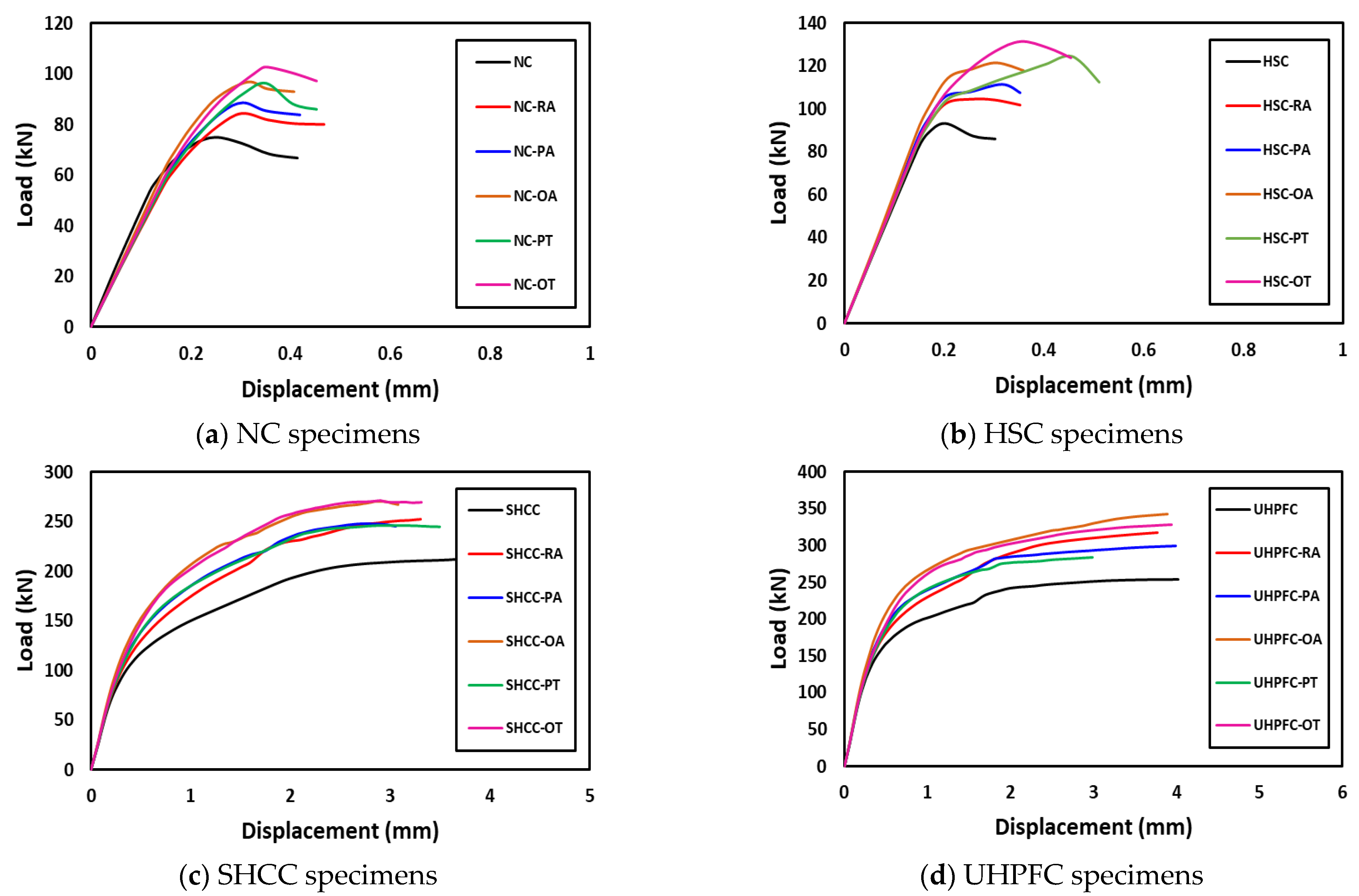
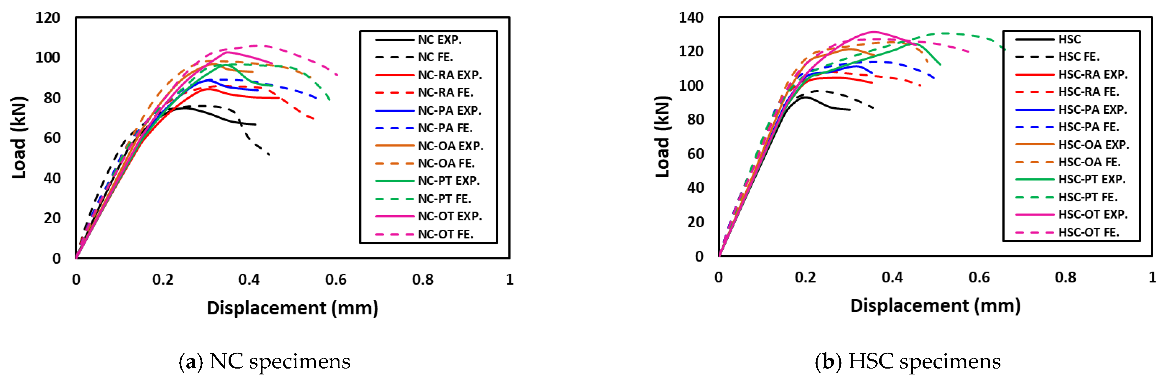
4.1. For NC and HSC Groups
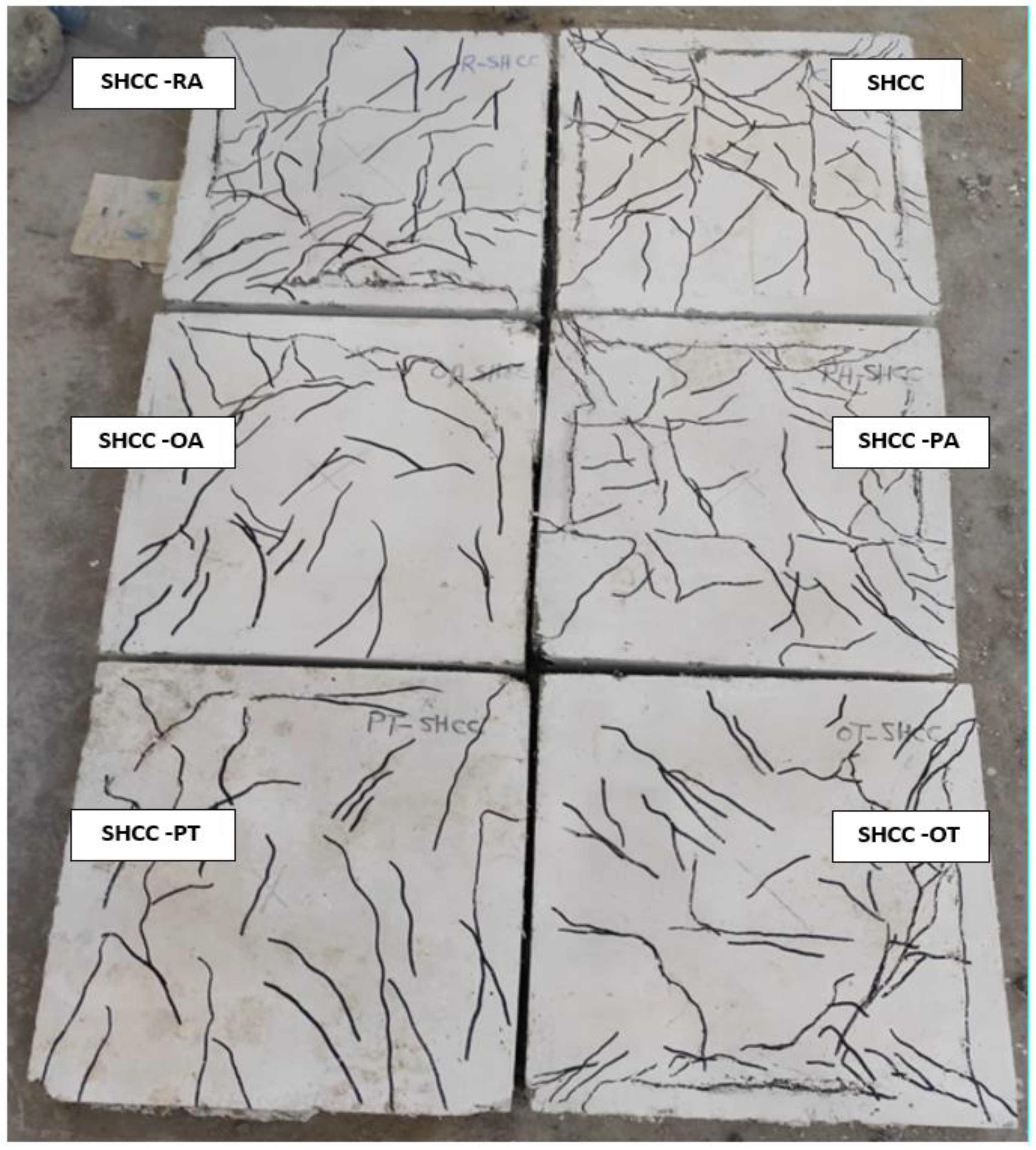
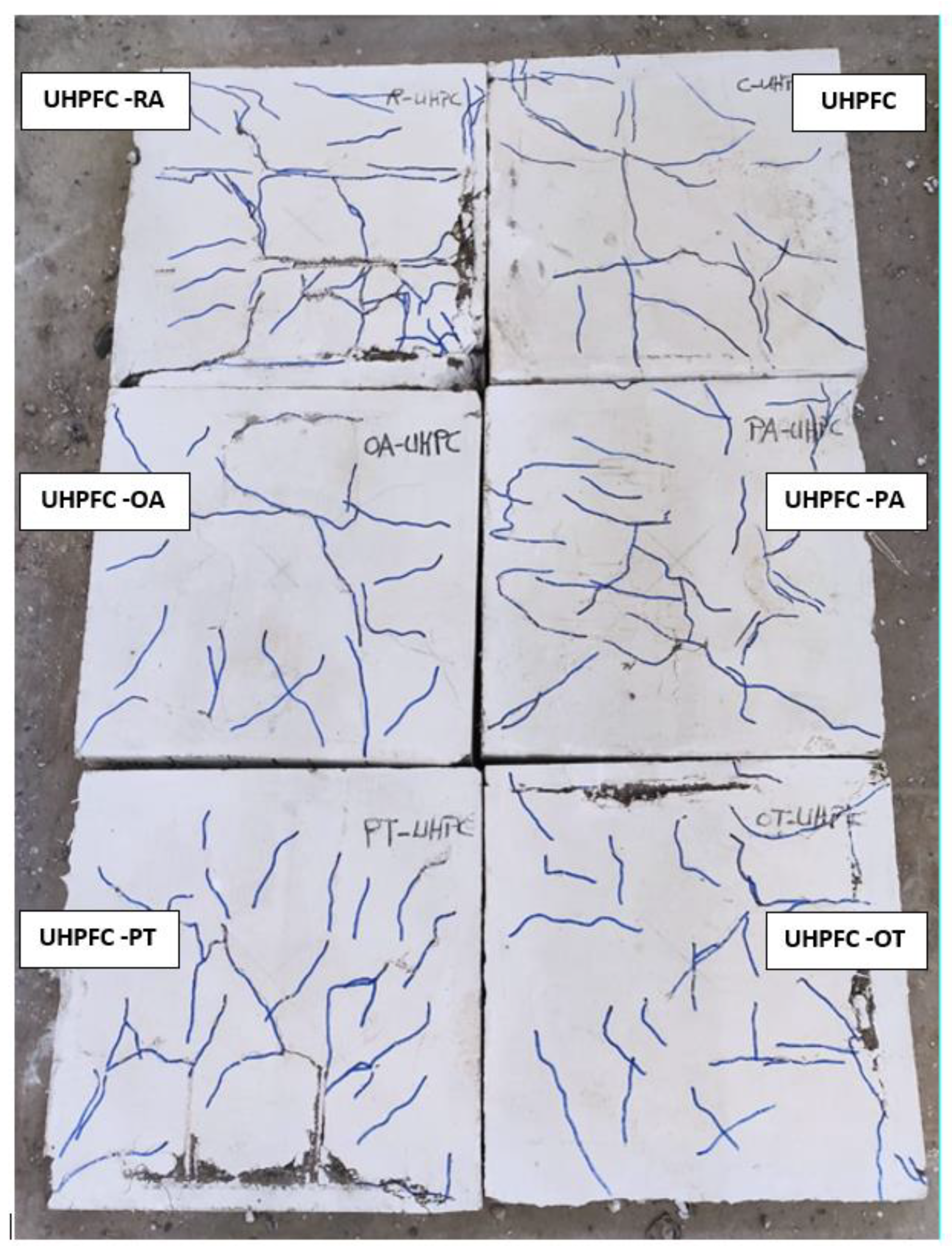
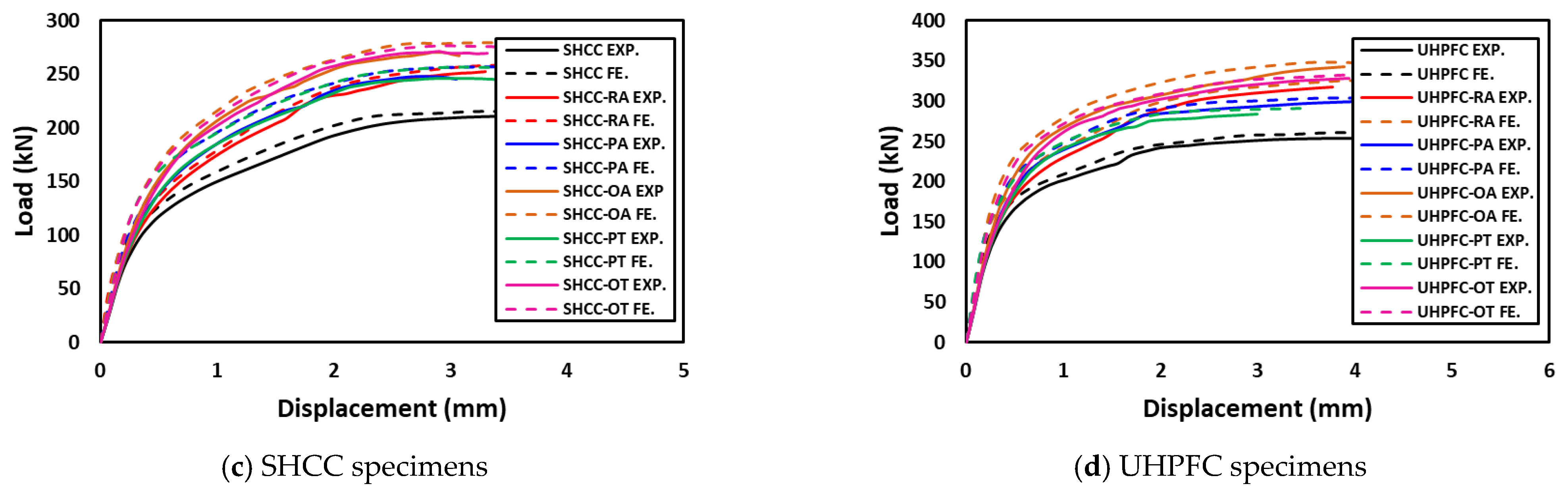
4.2. SHCC and UHPFC Groups
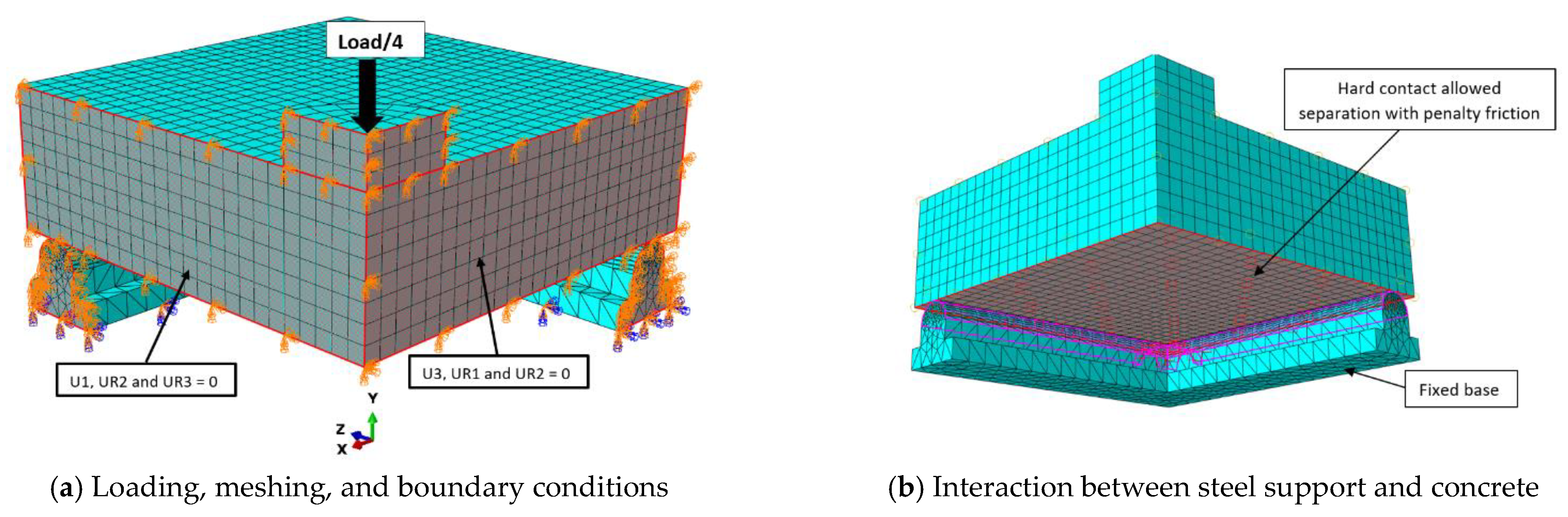
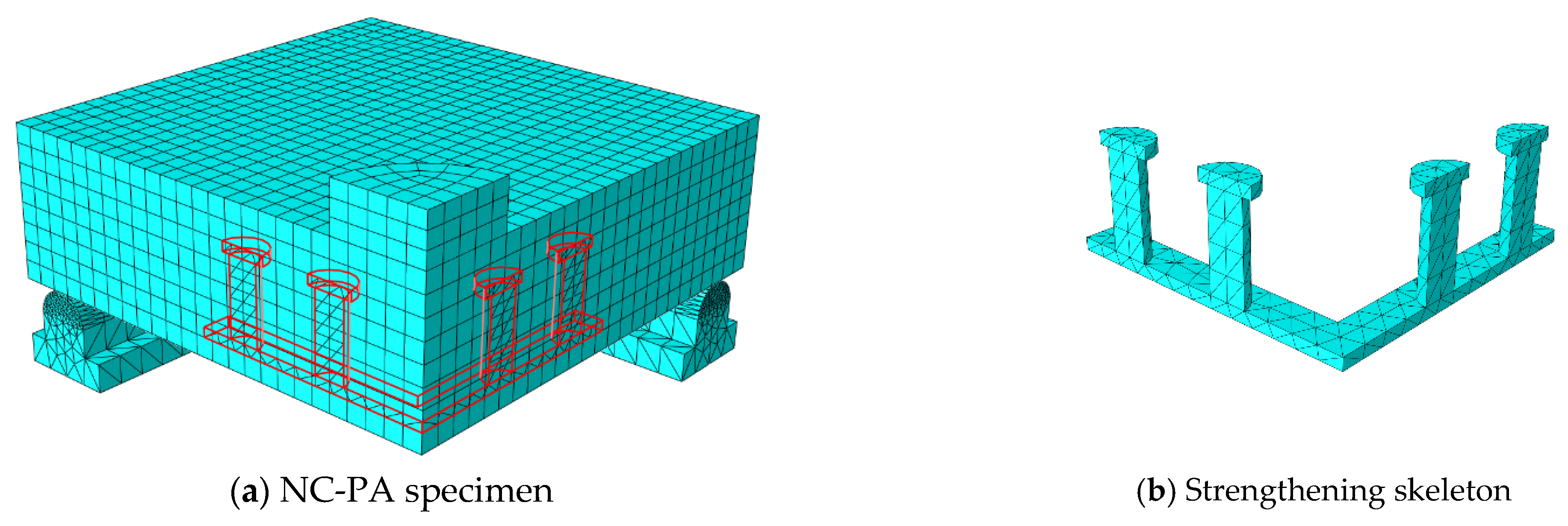
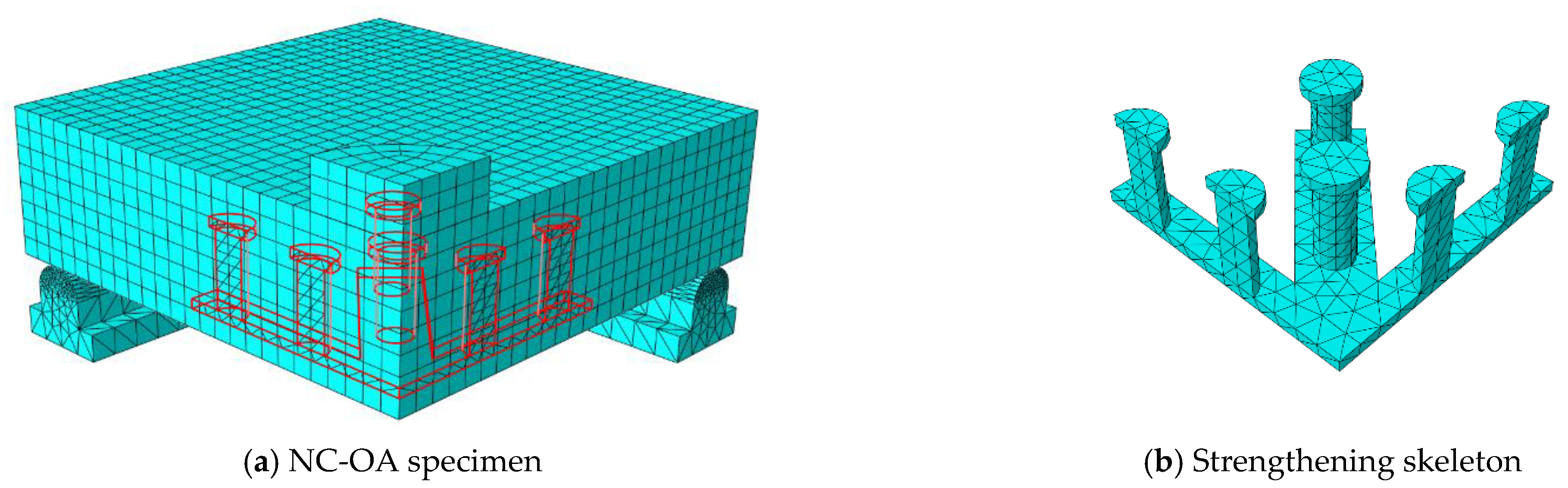
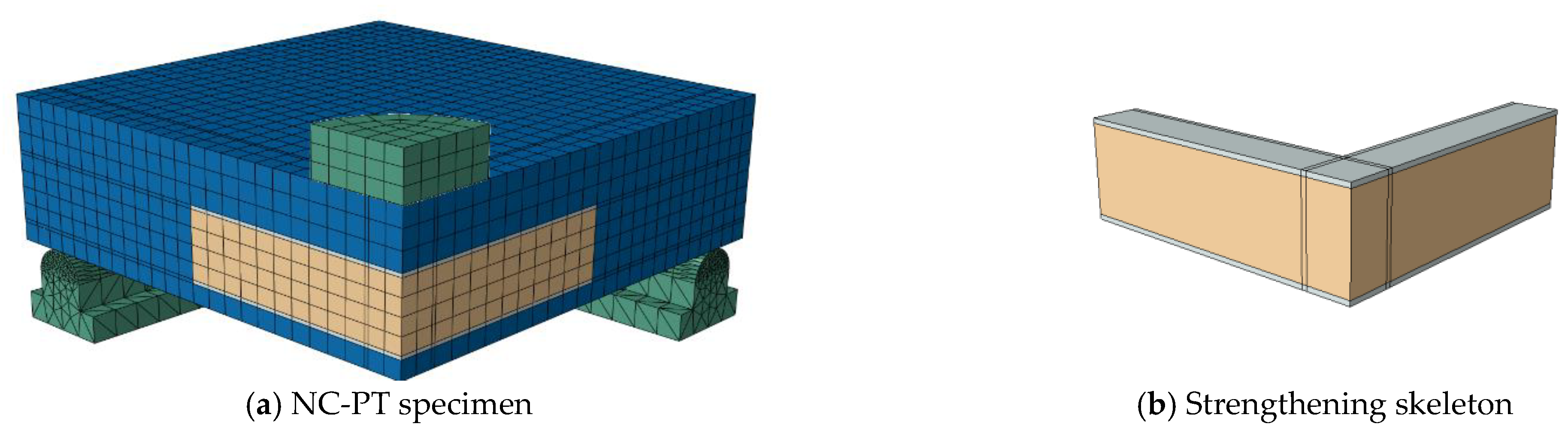
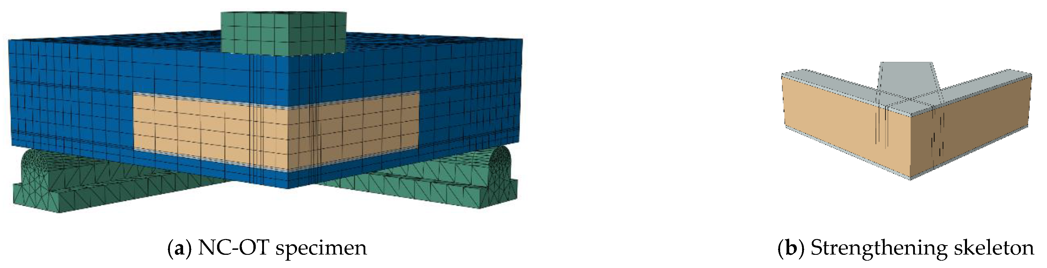
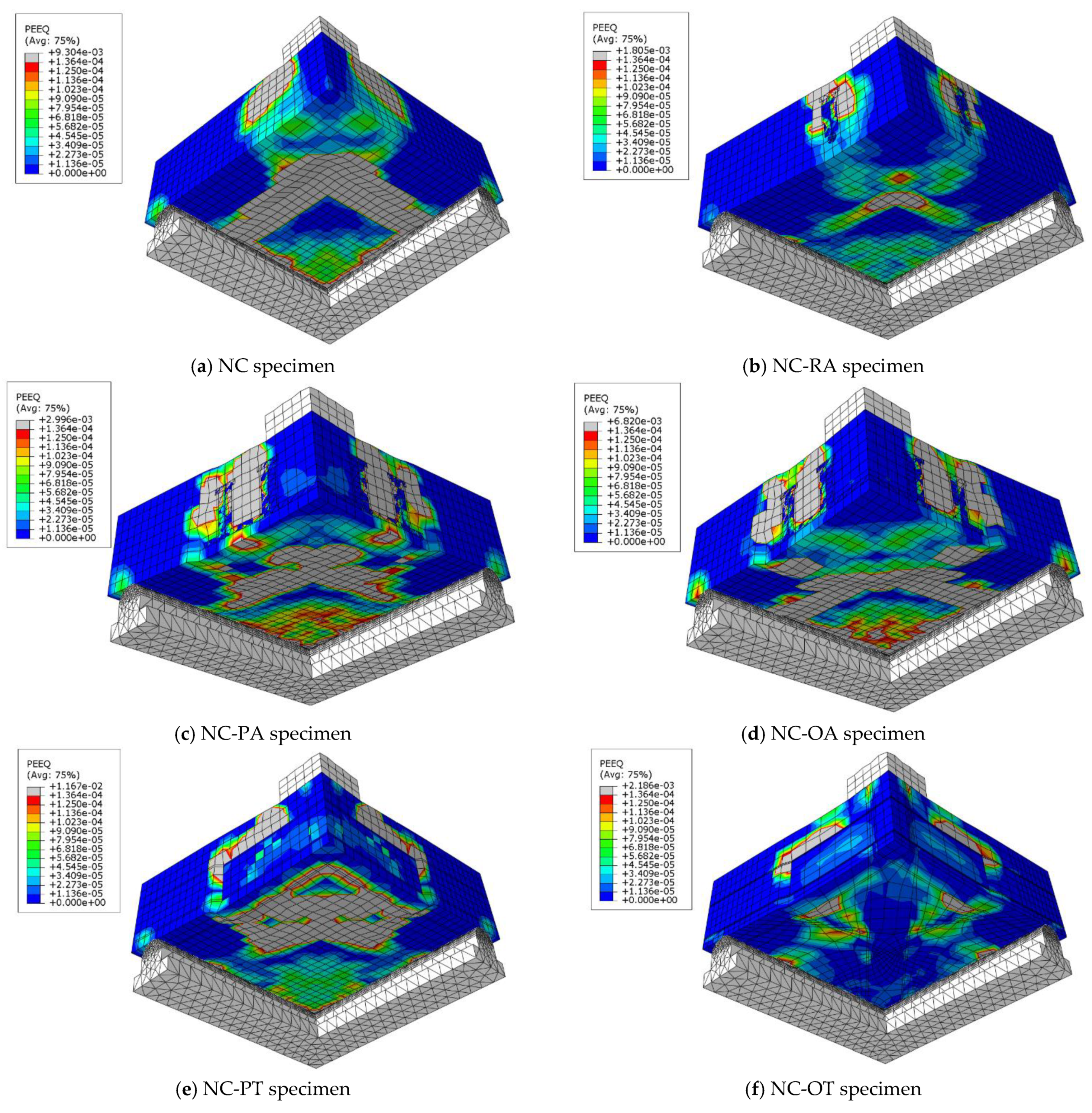
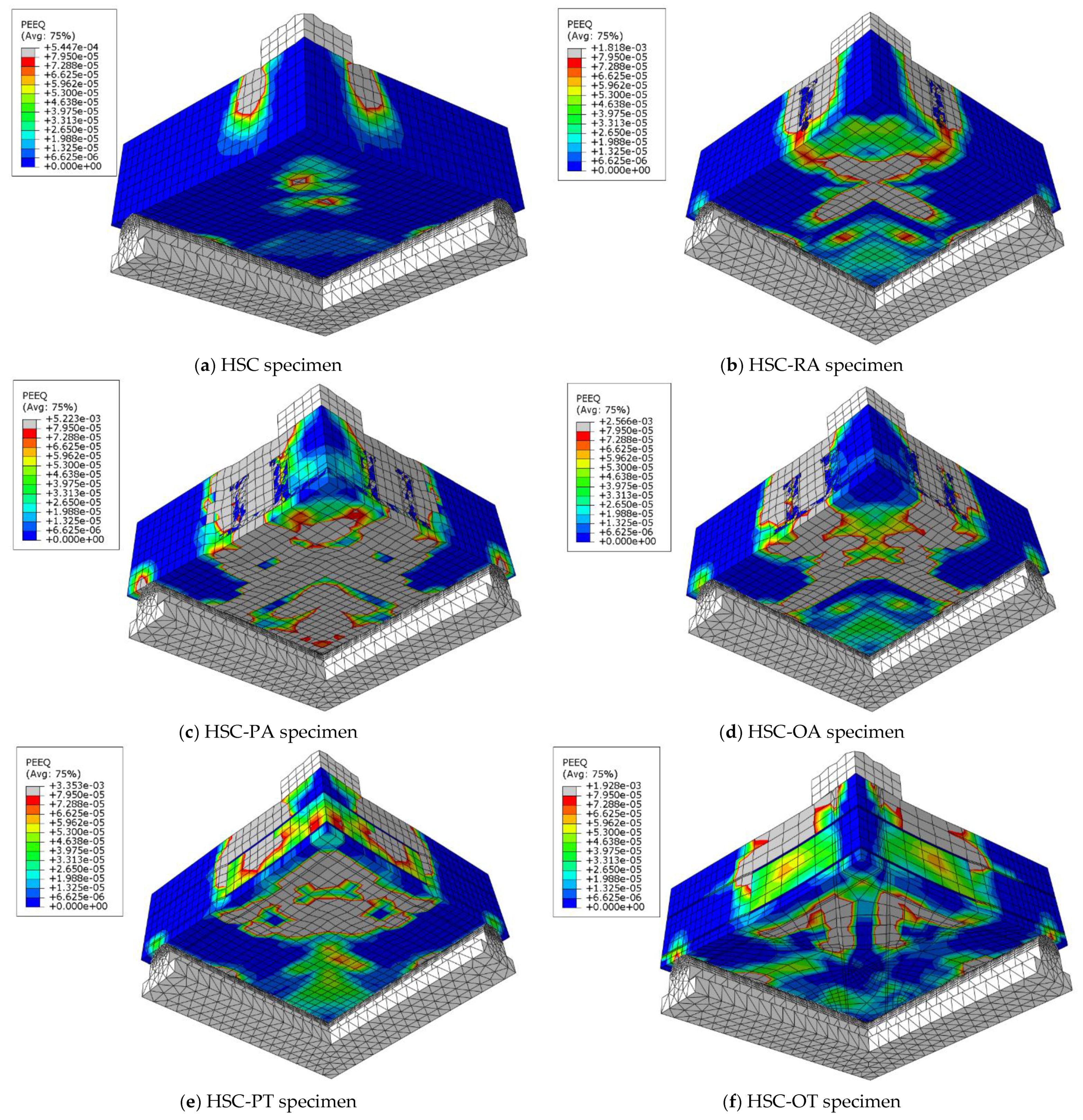
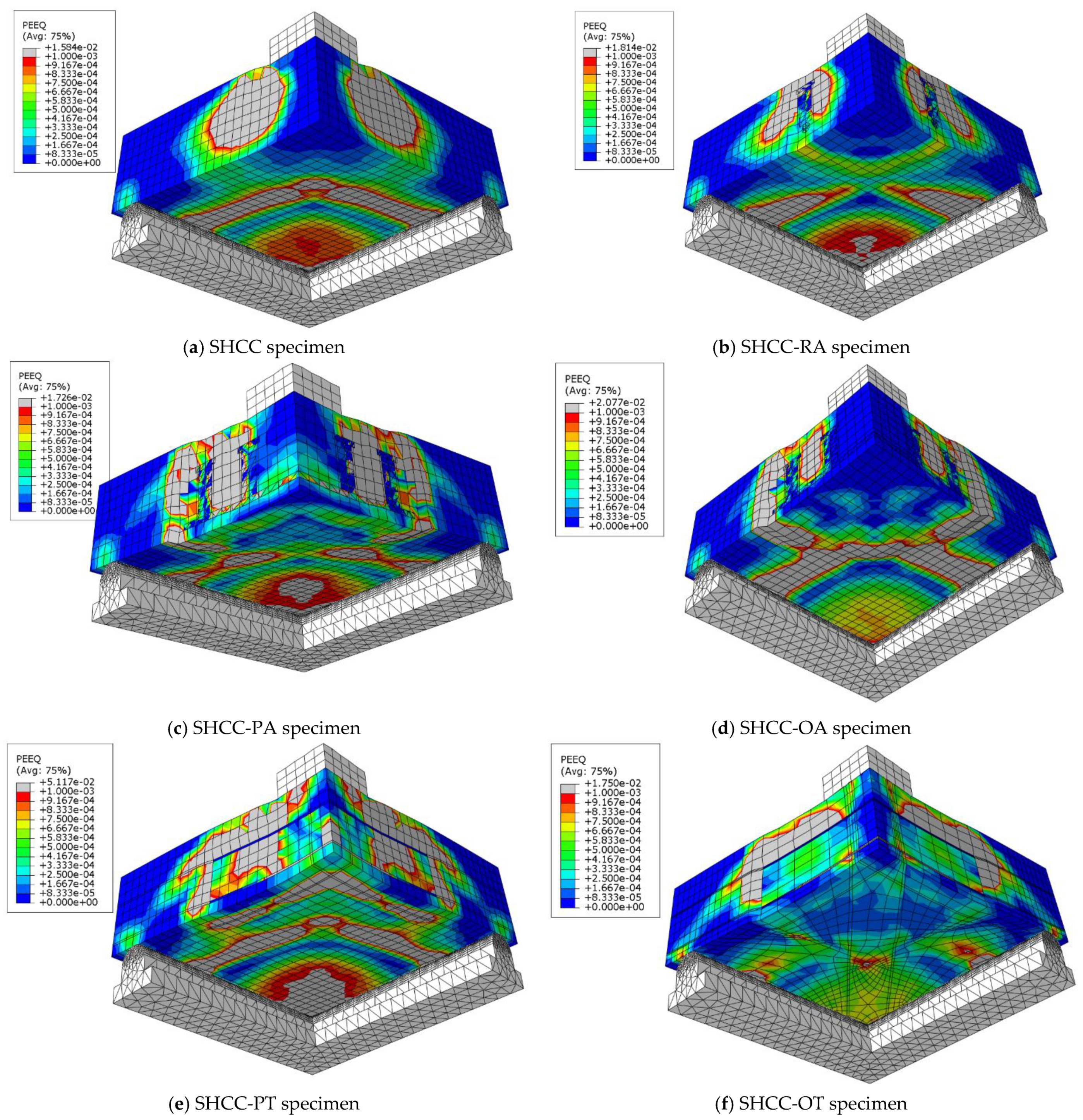
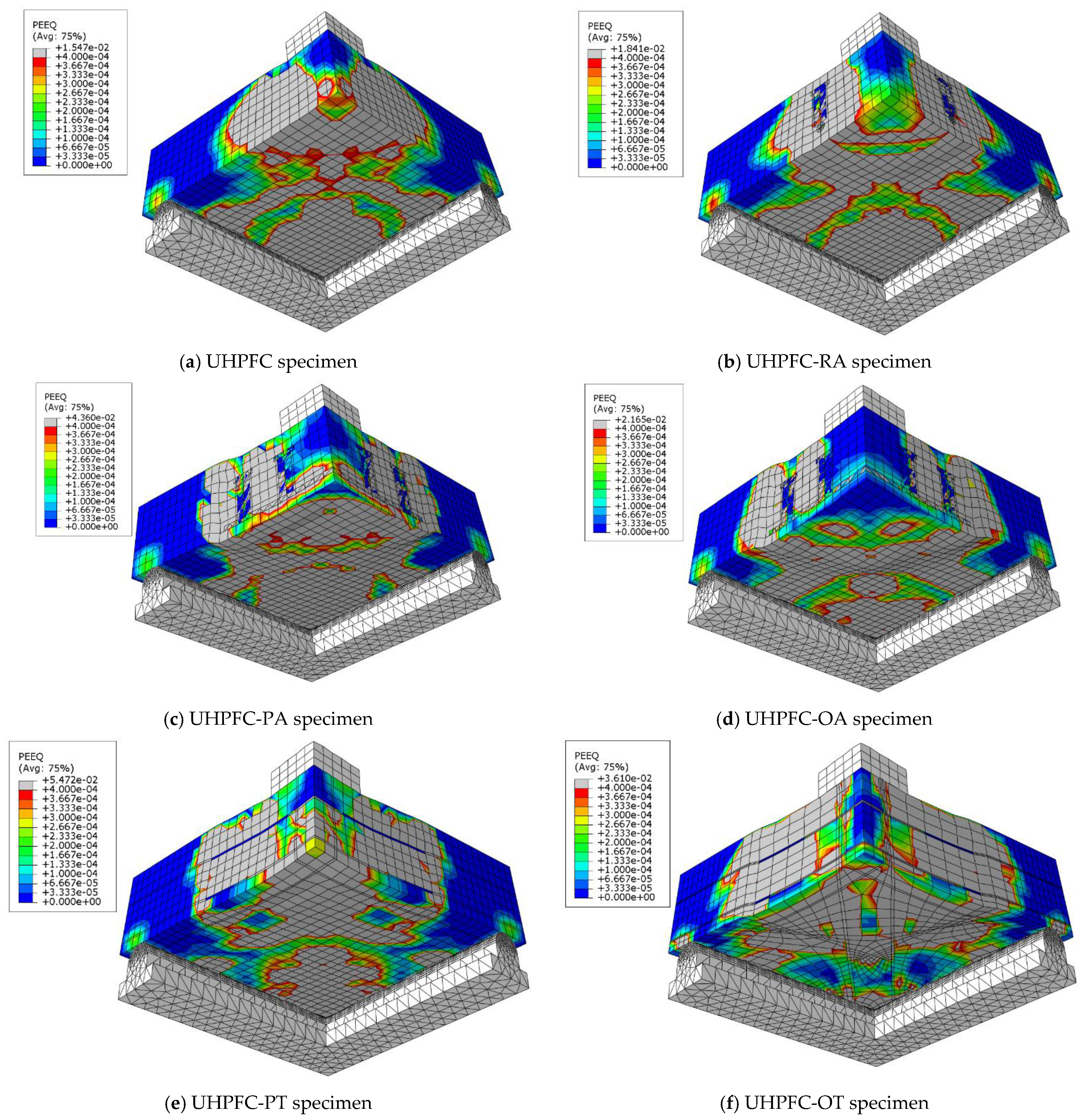
5. Numerical Modeling
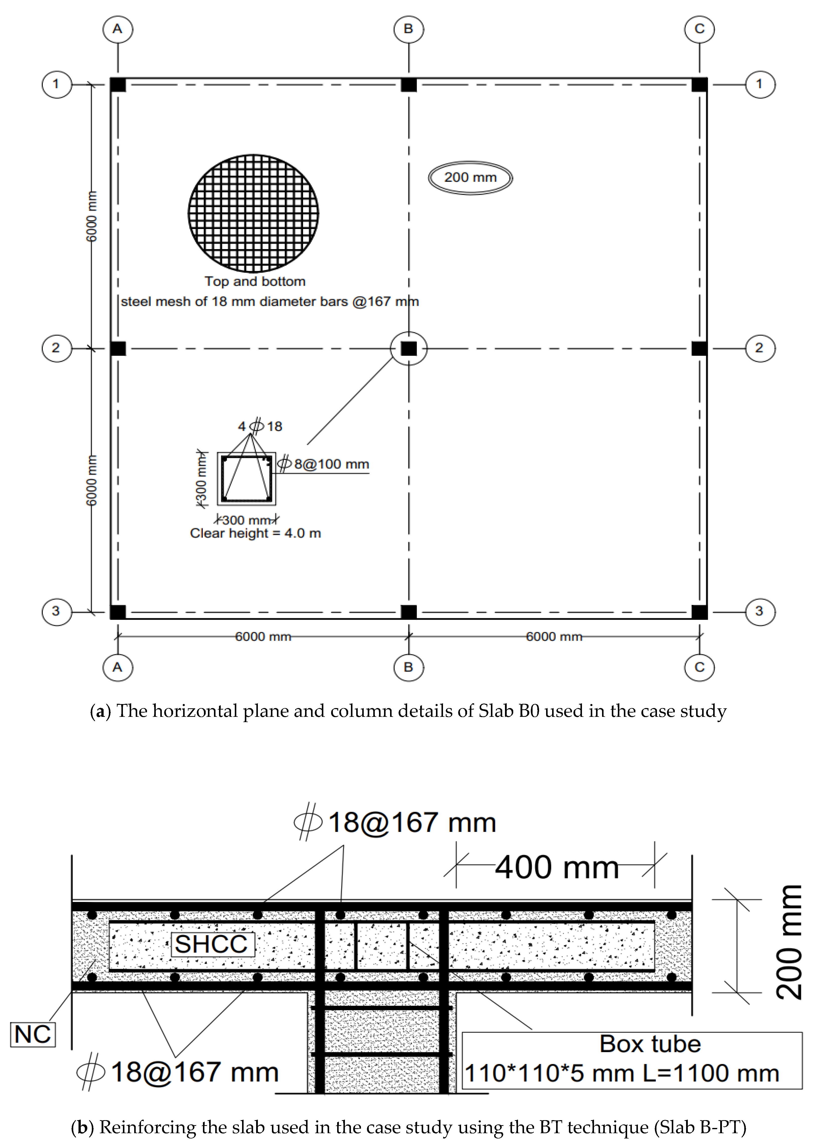
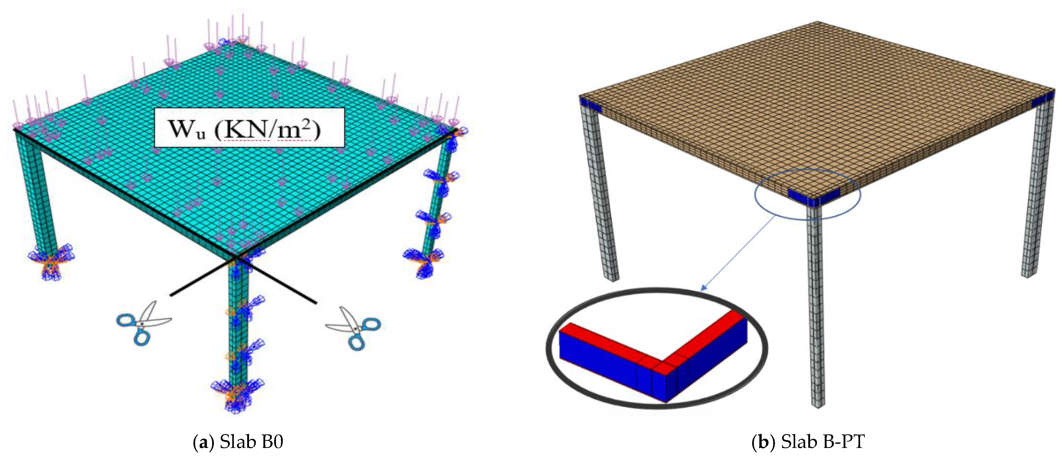
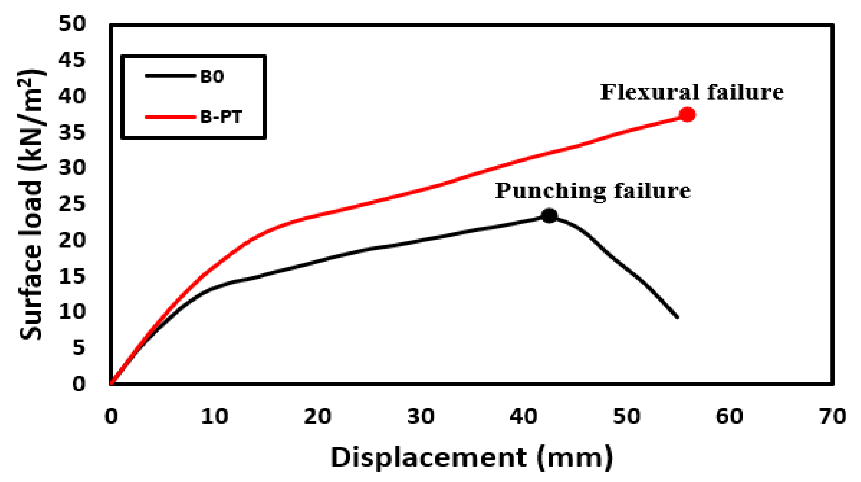
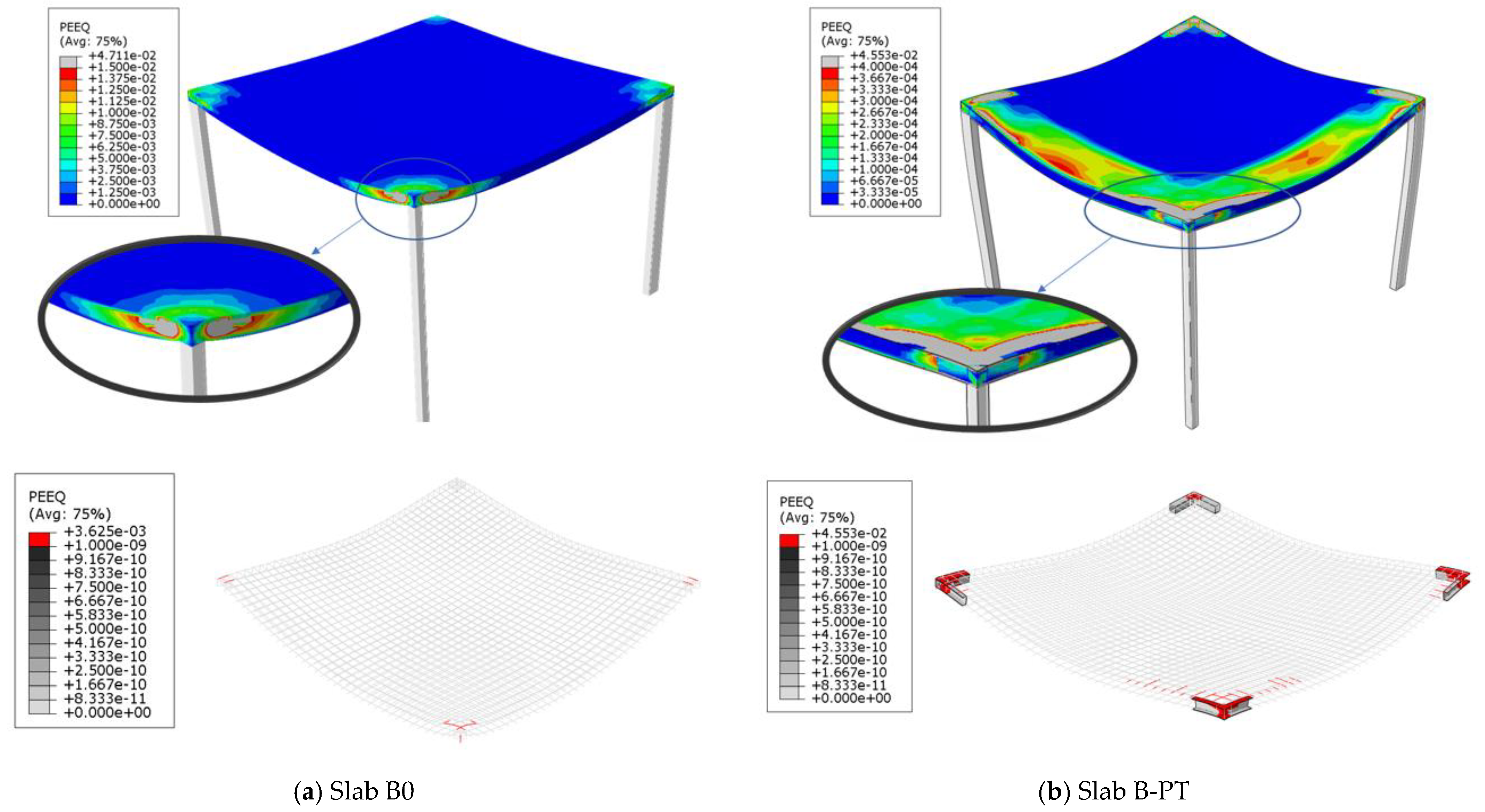
6. Case Study
7. Prediction of Punching Shear Load
8. Conclusions
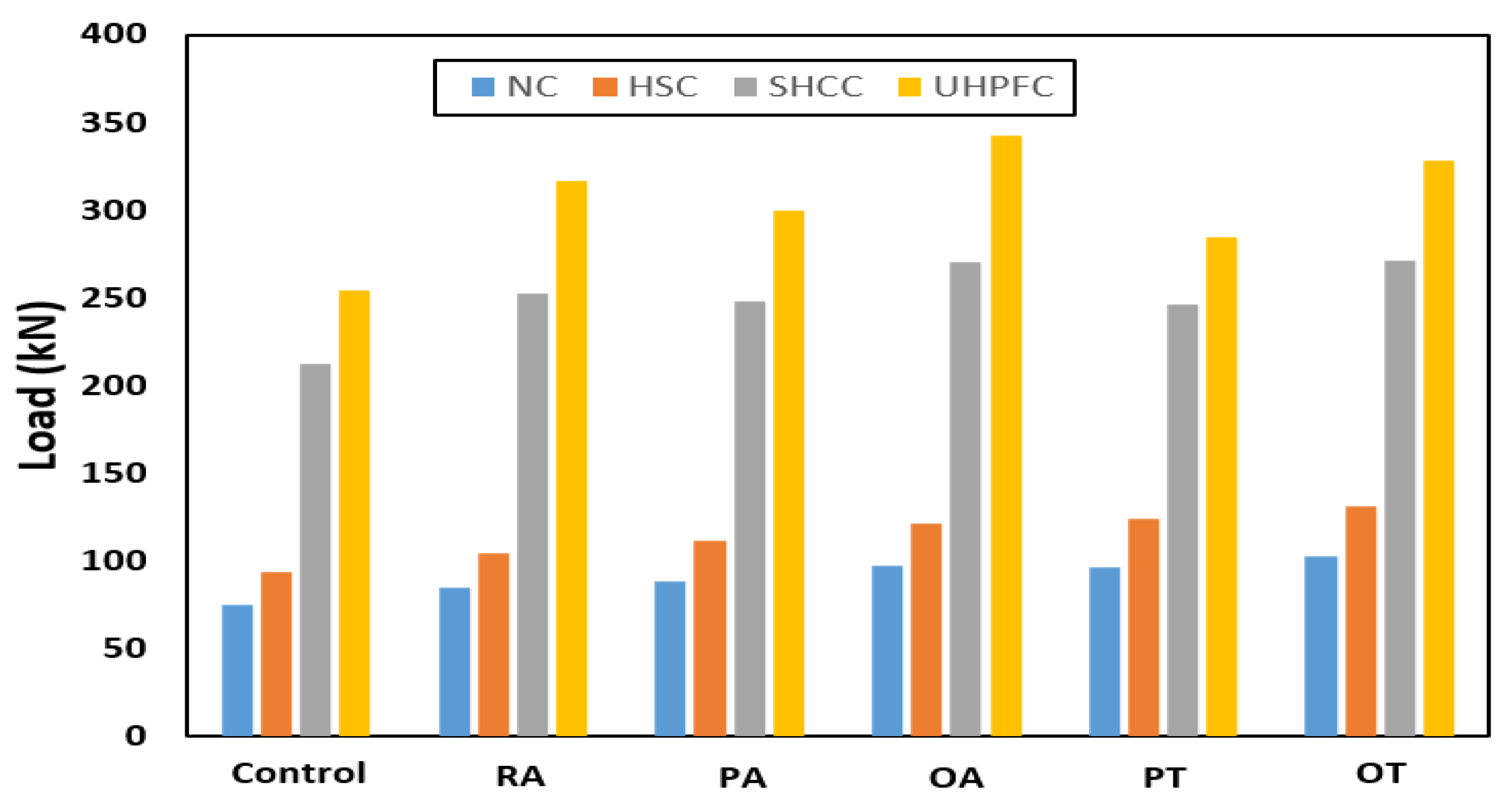
- By using steel assemblies embedded in the NC slabs, the punching shear capacity of the slab was increased but punching shear failure was not avoided.
- Internally unreinforced slabs made of SHCC and UHPFC were able to avoid punching shear failure and collapse in a ductile bending pattern due to the high compressive and tensile strength of these types of concrete.
- In the case that the dominant failure pattern on the control unreinforced slab is punching shear failure, the use of steel assemblies succeeded in moving the collapsed section from the vicinity of the column (loading) to the edge of the end of the steel assemblies.
- For slabs made of SHCC, the PT technique gave the largest ductility of 2.25, while the OT technique gave the largest increase in the ultimate load of the slab of 40%. For slabs made of UHPFC, the OT technique gave the largest ductility of 11.26, while the OA technique gave the largest increase in the slab ultimate load of 35%; this difference is due to the better tensile and compressive strength of UHPFC compared to SHCC.
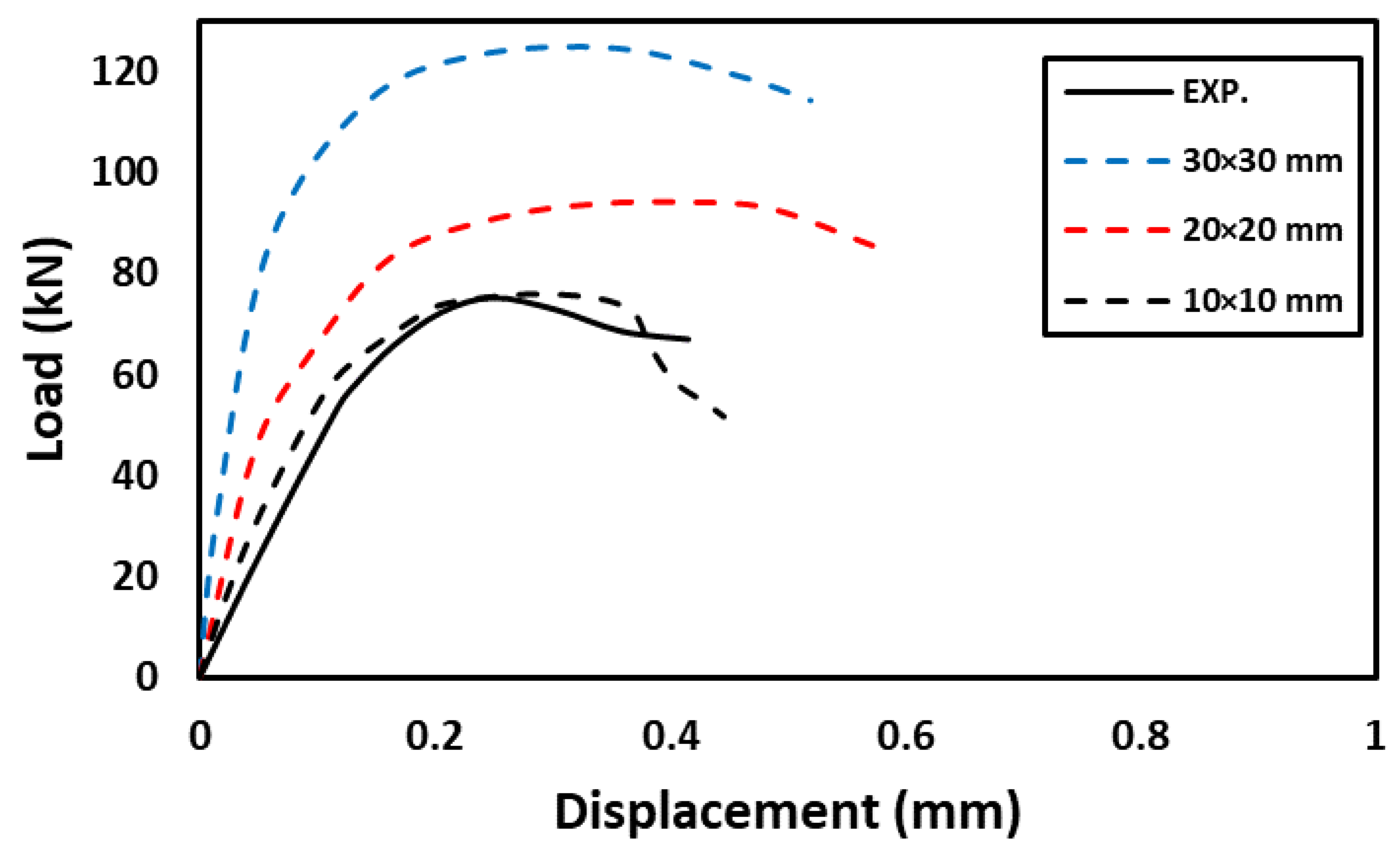
- The numerical modeling used to simulate the behavior of slabs made of NC, HSC, SHCC, and UHPFC, reinforced internally by steel assemblies in the high-stress region of the punching shear, was successful, which confirms the compatibility of the models of the materials used and the interaction method. The finite element method using the ABAQUS program is an effective method for analyzing the behavior of flat slabs.
- The proposed analytical method succeeded in predicting the collapse load of slabs reinforced with steel assemblies with a difference not exceeding 9%.
Author Contributions
Funding
Institutional Review Board Statement
Informed Consent Statement
Data Availability Statement
Conflicts of Interest
References
- Jang, J.-I.; Kang, S.-M. Punching Shear Behavior of Shear Reinforced Slab–Column Connection with Varying Flexural Reinforcement. Int. J. Concr. Struct. Mater. 2019, 13, 1–14. [Google Scholar] [CrossRef] [Green Version]
- Olmati, P.; Sagaseta, J.; Cormie, D.; Jones, A. Simplified reliability analysis of punching in reinforced concrete flat slab buildings under accidental actions. Eng. Struct. 2017, 130, 83–98. [Google Scholar] [CrossRef] [Green Version]
- ACI 352.1R–11. Guide for Design of Slab-Column Connections in Monolithic Concrete Structures; American Concrete Institute: Farmington Hills, MI, USA, 2011. [Google Scholar]
- Harajli, M.H.; Soudki, K.A. Shear Strengthening of Interior Slab–Column Connections Using Carbon Fiber-Reinforced Polymer Sheets. J. Compos. Constr. 2003, 7, 145–153. [Google Scholar] [CrossRef]
- Robertson, I.N.; Johnson, G. Repair of Slab–Column Connections Using Epoxy and Carbon Fiber Reinforced Polymer. J. Compos. Constr. 2004, 8, 376–383. [Google Scholar] [CrossRef]
- Polies, W.; Ghrib, F.; Sennah, K. Rehabilitation of interior reinforced concrete slab–column connections using CFRP sheets. Constr. Build. Mater. 2010, 24, 1272–1285. [Google Scholar] [CrossRef]
- Esfahani, M.; Kianoush, M.; Moradi, A. Punching shear strength of interior slab–column connections strengthened with carbon fiber reinforced polymer sheets. Eng. Struct. 2009, 31, 1535–1542. [Google Scholar] [CrossRef]
- ACI Committee 318. Building Code Requirements for Structural Concrete: (ACI 318); and Commentary (ACI 318R); American Concrete Institute: Farmington Hills, MI, USA, 2014. [Google Scholar]
- Abdullah, A.; Bailey, C.; Wu, Z. Tests investigating the punching shear of a column-slab connection strengthened with non-prestressed or prestressed FRP plates. Constr. Build. Mater. 2013, 48, 1134–1144. [Google Scholar] [CrossRef]
- Saleh, H.; Kalfat, R.; Abdouka, K.; Al-Mahaidi, R. Punching shear strengthening of RC slabs using L-CFRP laminates. Eng. Struct. 2019, 194, 274–289. [Google Scholar] [CrossRef]
- Akhundzada, H.; Donchev, T.; Petkova, D. Strengthening of slab-column connection against punching shear failure with CFRP laminates. Compos. Struct. 2019, 208, 656–664. [Google Scholar] [CrossRef] [Green Version]
- Huang, Z.; Zhao, Y.; Zhang, J.; Wu, Y. Punching Shear Behaviour of Concrete Slabs Reinforced with CFRP grids. In Structures; Elsevier: Amsterdam, The Netherlands, 2020; Volume 26, pp. 617–625. [Google Scholar] [CrossRef]
- Hamoda, A.; Hossain, K.M.A. Numerical Assessment of Slab–Column Connection Additionally Reinforced with Steel and CFRP Bars. Arab. J. Sci. Eng. 2019, 44, 8181–8204. [Google Scholar] [CrossRef]
- Eren, N.A. Punching shear behavior of geopolymer concrete two-way flat slabs incorporating a combination of nano silica and steel fibers. Constr. Build. Mater. 2022, 346, 128351. [Google Scholar] [CrossRef]
- Gołdyn, M.; Urban, T. UHPFRC hidden capitals as an alternative method for increasing punching shear resistance of LWAC flat slabs. Eng. Struct. 2022, 271, 114906. [Google Scholar] [CrossRef]
- Alrousan, R.Z.; Alnemrawi, B.R. The influence of concrete compressive strength on the punching shear capacity of reinforced concrete flat slabs under different opening configurations and loading conditions. In Structures; Elsevier: Amsterdam, The Netherlands, 2022; Volume 44, pp. 101–119. [Google Scholar] [CrossRef]
- El-Kassas, A.I.; Bashandy, A.A.; Eied, F.-A.M.; Arab, M.A.E.-S. Effect of fibers type on the behavior of fibrous high-strength self-compacted reinforced concrete flat slabs in punching with and without shear reinforcement. Constr. Build. Mater. 2022, 360, 129625. [Google Scholar] [CrossRef]
- Alrudaini, T.M.S. A rational formula to predict punching shear capacity at interior columns connections with RC flat slabs reinforced with either steel or FRP bars but without shear reinforcement. In Structures; Elsevier: Amsterdam, The Netherlands, 2022; Volume 37, pp. 56–68. [Google Scholar] [CrossRef]
- Sine, A.; Pimentel, M.; Nunes, S. Experimental investigation on punching shear behaviour of RC-(R)UHPFRC composite flat slabs without transverse reinforcement. Eng. Struct. 2022, 255, 113951. [Google Scholar] [CrossRef]
- Zamri, N.F.; Mohamed, R.N.; Awalluddin, D.; Abdullah, R. Experimental evaluation on punching shear resistance of steel fibre reinforced self-compacting concrete flat slabs. J. Build. Eng. 2022, 52, 104441. [Google Scholar] [CrossRef]
- Shatarat, N.; Salman, D. Investigation of punching shear behavior of flat slabs with different types and arrangements of shear reinforcement. Case Stud. Constr. Mater. 2022, 16, e01028. [Google Scholar] [CrossRef]
- De Oliveira, V.H.D.; de Lima, H.J.N.; Melo, G.S. Punching shear resistance of flat slabs with different types of stirrup anchorages such as shear reinforcement. Eng. Struct. 2022, 253, 113671. [Google Scholar] [CrossRef]
- El-Shafiey, T.F.; Atta, A.M.; Hassan, A.; Elnasharty, M. Effect of opening shape, size and location on the punching shear behaviour of RC flat slabs. In Structures; Elsevier: Amsterdam, The Netherlands, 2022; Volume 44, pp. 1138–1151. [Google Scholar] [CrossRef]
- Elsamak, G.; Fayed, S. Parametric studies on punching shear behavior of RC flat slabs without shear reinforcement. Comput. Concr. 2020, 25, 355–367. [Google Scholar]
- Harajli, M.H.; Soudki, K.A.; Kudsi, T. Strengthening of Interior Slab–Column Connections Using a Combination of FRP Sheets and Steel Bolts. J. Compos. Constr. 2006, 10, 399–409. [Google Scholar] [CrossRef]
- Adetifa, B.; Polak, M.A. Retrofit of slab column interior connections using shear bolts. ACI Struct. J. 2005, 102, 268. [Google Scholar]
- Baig, Z.I.; Alsayed, S.H.; Abbas, H. Punching of slab–column connections strengthened using external steel shear bolts. Mag. Concr. Res. 2016, 68, 55–68. [Google Scholar] [CrossRef]
- Saleh, H.; Kalfat, R.; Abdouka, K.; Al-Mahaidi, R. Experimental and numerical study into the punching shear strengthening of RC flat slabs using post-installed steel bolts. Constr. Build. Mater. 2018, 188, 28–39. [Google Scholar] [CrossRef]
- Gomes, R.; Regant, P. Punching strength of slabs reinforced for shear with offcuts of rolled steel I-section beams. Mag. Concr. Res. 1999, 51, 121–129. [Google Scholar] [CrossRef]
- Bompa, D.; Elghazouli, A. Structural performance of RC flat slabs connected to steel columns with shear heads. Eng. Struct. 2016, 117, 161–183. [Google Scholar] [CrossRef] [Green Version]
- Bompa, D.V.; Elghazouli, A.Y. Nonlinear numerical simulation of punching shear behavior of reinforced concrete flat slabs with shear-heads. Front. Struct. Civ. Eng. 2020, 14, 331–356. [Google Scholar] [CrossRef] [Green Version]
- Ngekpe, B.E.; Abbey, S.J.; Olubanwo, A.O. Structural performance of a modified shear-head assembly for edge steel column embedded in reinforced concrete slab. Eng. Solid Mech. 2019, 7, 59–70. [Google Scholar] [CrossRef]
- Zhou, L.; Huang, Y.; Chen, B. Punching shear behavior of slab–column connections embedded with steel skeletons. In Structures; Elsevier: Amsterdam, The Netherlands, 2021; Volume 33, pp. 2879–2892. [Google Scholar] [CrossRef]
- Afefy, H.M.; El-Tony, E.T.M. Punching shear resistance of strengthened reinforced concrete interior slab–column connections using ultra-high-performance strain-hardening cementitious composite material. Adv. Struct. Eng. 2019, 22, 1799–1816. [Google Scholar] [CrossRef]
- Hassan, A.; Mahmud, G.; Jones, S.; Whitford, C. A new test method for investigating punching shear strength in Ultra High Performance Fibre Reinforced Concrete (UHPFRC) slabs. Compos. Struct. 2015, 131, 832–841. [Google Scholar] [CrossRef] [Green Version]
- Abaqus Theory Manual; Dassault Systemes: Providence, RI, USA, 2014.
- Zeng, J.J.; Zeng, W.B.; Ye, Y.Y.; Liao, J.; Zhuge, Y.; Fan, T.H. Flexural behavior of FRP grid reinforced ul-tra-high-performance concrete composite plates with different types of fibers. Eng. Struct. 2022, 272, 115020. [Google Scholar] [CrossRef]
- Carreira, D.J.; Chu, K.H. Stress-strain relationship for plain concrete in compression. J. Proc. 1985, 82, 797–804. [Google Scholar]
- Zhou, J.; Pan, J.; Leung, C.K.Y. Mechanical Behavior of Fiber-Reinforced Engineered Cementitious Composites in Uniaxial Compression. J. Mater. Civ. Eng. 2015, 27, 04014111. [Google Scholar] [CrossRef]
- Muttoni, A.; Ruiz, M.F. The levels-of-approximation approach in MC 2010: Application to punching shear provisions. Struct. Concr. 2012, 13, 32–41. [Google Scholar] [CrossRef]
- Timoshenko, S.; Woinowsky-Krieger, S. Theory of Plates and Shells; McGraw-Hil: New York, NY, USA, 1959; Volume 2, pp. 240–246. [Google Scholar]
- Elstner, R.C.; Hognestad, E. Shearing strength of reinforced concrete slabs. J. Proc. 1956, 53, 29–58. [Google Scholar]


| Group | Slab ID | Concrete Grade | Type of Steel Skelton |
|---|---|---|---|
| 1 | NC | NC | - |
| NC-RA | NC | RA | |
| NC-PA | NC | PA | |
| NC-OA | NC | OA | |
| NC-PT | NC | PT | |
| NC-OT | NC | OT | |
| 2 | HSC | HSC | - |
| HSC-RA | HSC | RA | |
| HSC-PA | HSC | PA | |
| HSC-OA | HSC | OA | |
| HSC-PT | HSC | PT | |
| HSC-OT | HSC | OT | |
| 3 | SHCC | SHCC | - |
| SHCC-RA | SHCC | RA | |
| SHCC-PA | SHCC | PA | |
| SHCC-OA | SHCC | OA | |
| SHCC-PT | SHCC | PT | |
| SHCC-OT | SHCC | OT | |
| 4 | UHPFC | UHPFC | - |
| UHPFC-RA | UHPFC | RA | |
| UHPFC-PA | UHPFC | PA | |
| UHPFC-OA | UHPFC | OA | |
| UHPFC-PT | UHPFC | PT | |
| UHPFC-OT | UHPFC | OT |
| Type | Cement | Fly Ash | Silica Fume | Sand | Crushed Basalt | Fibers | Water | Superplasticizer |
|---|---|---|---|---|---|---|---|---|
| NC | 332 | - | 662 | 830 | - | 206 | - | |
| HSC | 460 | 80 | 54 | 600 | 980 | - | 130.7 | 9.2 |
| SHCC | 1300 | - | 230 | 146 | 15 PPF* | 297 | 30.0 | |
| UHPFC | 900 | - | 220 | 1005 | 157 SF* | 162.4 | 40.3 |
| Sample | Δy (mm) | Δu (mm) | Pcr*(kN) | Py* (kN) | Pu (kN) | Ductility (m) | Pu/PControl | Pu/(√ fc’ × b0 × d) | Failure Mode |
|---|---|---|---|---|---|---|---|---|---|
| NC | - | 0.25 | 13.40 | - | 75.10 | - | 1 | 0.332 | Punching |
| NC-RA | - | 0.30 | 14.10 | - | 84.60 | - | 1.13 | 0.374 | Punching |
| NC-PA | - | 0.30 | 14.60 | - | 88.65 | - | 1.18 | 0.392 | Punching |
| NC-OA | - | 0.31 | 15.60 | - | 96.90 | - | 1.29 | 0.428 | Punching |
| NC-PT | - | 0.35 | 14.40 | - | 96.25 | - | 1.28 | 0.426 | Punching |
| NC-OT | - | 0.35 | 14.80 | - | 102.90 | - | 1.37 | 0.455 | Punching |
| HSC | - | 0.20 | 20.40 | - | 93.50 | - | 1 | 0.328 | Punching |
| HSC-RA | - | 0.26 | 21.10 | - | 104.65 | - | 1.12 | 0.367 | Punching |
| HSC-PA | - | 0.32 | 21.60 | - | 111.50 | - | 1.19 | 0.391 | Punching |
| HSC-OA | - | 0.30 | 22.60 | - | 121.40 | - | 1.30 | 0.425 | Punching |
| HSC-PT | - | 0.45 | 21.00 | - | 124.40 | - | 1.33 | 0.436 | Punching |
| HSC-OT | - | 0.35 | 21.30 | - | 131.30 | - | 1.40 | 0.460 | Punching |
| SHCC | 2.20 | 3.65 | 13.60 | 51.10 | 211.90 | Δu/Δy = 1.66 | 1 | 0.640 | Flexural |
| SHCC-RA | 1.30 | 3.30 | 14.16 | 50.90 | 252.40 | 2.54 | 1.19 | 0.770 | Flexural |
| SHCC-PA | 2.14 | 2.76 | 14.60 | 60.70 | 248.00 | 1.29 | 1.17 | 0.757 | Flexural |
| SHCC-OA | 0.64 | 2.85 | 15.40 | 46.10 | 270.60 | 4.45 | 1.28 | 0.820 | Flexural |
| SHCC-PT | 0.36 | 2.94 | 14.30 | 32.40 | 246.50 | 8.17 | 1.16 | 0.750 | Flexural |
| SHCC-OT | 0.41 | 2.90 | 14.70 | 36.90 | 271.10 | 7.07 | 1.28 | 0.820 | Flexural |
| UHPFC | 1.75 | 4.02 | 19.00 | 60.50 | 254.40 | 2.3 | 1 | 0.630 | Flexural |
| UHPFC-RA | 1.02 | 3.75 | 19.60 | 67.60 | 317.06 | 3.68 | 1.25 | 0.780 | Flexural |
| UHPFC-PA | 0.44 | 4.00 | 20.00 | 50.50 | 299.45 | 9.1 | 1.18 | 0.740 | Flexural |
| UHPFC-OA | 0.51 | 3.90 | 20.80 | 58.20 | 342.70 | 7.65 | 1.35 | 0.840 | Flexural |
| UHPFC-PT | 0.36 | 3.00 | 19.50 | 45.10 | 284.30 | 8.33 | 1.12 | 0.700 | Flexural |
| UHPFC-OT | 0.35 | 3.94 | 19.70 | 45.90 | 328.10 | 11.26 | 1.29 | 0.810 | Flexural |
| Concrete | |||||||
|---|---|---|---|---|---|---|---|
| Type | Elastic Modulus E (N/mm2) | Poisson Ratio (ν) | Dilation Angle (ψ) | Eccentricity (e) | Shape Parameter (Kc) | (fbo/fco) Maximum Compression Axial/Biaxial | Viscosity (μ) |
| NSC | 31,600 | 0.2 | 30° | 0.1 | 0.667 | 1.16 | 0 |
| HSC | 55,000 | 0.2 | 30° | ||||
| SHCC | 29,100 | 0.17 | 35° | ||||
| UHPFC | 46,000 | 0.15 | 36° | ||||
| Steel | |||||||
| Type | Elastic Modulus E (N/mm2) | Poisson Ratio ν | Yield Stress (N/mm2) | ||||
| Longitudinal reinforcement | 200,000 | 0.3 | 413 | ||||
| Steel sections | 190,707 | 0.3 | 240 | ||||
| Bolts | 200,000 | 0.3 | 900 | ||||
| Specimen | Max. FE Displacement Δu FE. (mm) | Max. EXP. Displacement Δu EXP. (mm) | Δu FE./Δu EXP. | Max. FE Failure Load Pu FE. (kN) | Max. EXP. Failure Load Pu EXP. (kN) | Pu FE./Pu EXP. | Vu an.* | Vu an./Pu EXP. |
|---|---|---|---|---|---|---|---|---|
| NC | 0.27 | 0.25 | 1.08 | 75.90 | 75.10 | 1.01 | 71.20 | 0.95 |
| NC-RA | 0.32 | 0.30 | 1.07 | 85.70 | 84.60 | 1.01 | 82.30 | 0.97 |
| NC-PA | 0.33 | 0.30 | 1.10 | 89.25 | 88.65 | 1.01 | 85.30 | 0.96 |
| NC-OA | 0.33 | 0.31 | 1.06 | 98.25 | 96.90 | 1.01 | 92.15 | 0.95 |
| NC-PT | 0.36 | 0.35 | 1.03 | 96.80 | 96.25 | 1.01 | 94.16 | 0.98 |
| NC-OT | 0.37 | 0.35 | 1.06 | 105.40 | 102.90 | 1.02 | 101.3 | 0.98 |
| HSC | 0.21 | 0.20 | 1.05 | 96.50 | 93.50 | 1.03 | 89.50 | 0.96 |
| HSC-RA | 0.24 | 0.26 | 0.92 | 107.8 | 104.65 | 1.03 | 99.40 | 0.95 |
| HSC-PA | 0.40 | 0.32 | 1.25 | 113.70 | 111.50 | 1.02 | 103.20 | 0.93 |
| HSC-OA | 0.42 | 0.30 | 1.25 | 125.10 | 121.40 | 1.03 | 115.30 | 0.95 |
| HSC-PT | 0.51 | 0.45 | 1.13 | 131.00 | 124.40 | 1.05 | 117.20 | 0.94 |
| HSC-OT | 0.40 | 0.35 | 1.14 | 127.20 | 131.30 | 0.97 | 121.30 | 0.94 |
| SHCC | 3.20 | 3.65 | 0.88 | 215.20 | 211.90 | 1.02 | 195.90 | 0.92 |
| SHCC-RA | 3.45 | 3.30 | 1.05 | 259.10 | 252.40 | 1.03 | 230.20 | 0.91 |
| SHCC-PA | 3.17 | 2.76 | 1.15 | 256.40 | 248.00 | 1.03 | 230.40 | 0.93 |
| SHCC-OA | 3.20 | 2.85 | 1.12 | 279.70 | 270.60 | 1.03 | 260.15 | 0.96 |
| SHCC-PT | 2.95 | 2.94 | 1.01 | 256.50 | 246.50 | 1.04 | 235.15 | 0.95 |
| SHCC-OT | 2.83 | 2.90 | 0.98 | 276.20 | 271.10 | 1.02 | 262.40 | 0.97 |
| UHPFC | 3.70 | 4.02 | 0.92 | 260.80 | 254.40 | 1.03 | 245.20 | 0.96 |
| UHPFC-RA | 4.10 | 3.75 | 1.09 | 325.30 | 317.06 | 1.03 | 313.15 | 0.99 |
| UHPFC-PA | 3.70 | 4.00 | 0.93 | 303.90 | 299.45 | 1.02 | 285.20 | 0.95 |
| UHPFC-OA | 3.58 | 3.90 | 0.92 | 348.30 | 342.70 | 1.02 | 345.15 | 1.00 |
| UHPFC-PT | 3.50 | 3.00 | 1.17 | 290.80 | 284.30 | 1.02 | 275.20 | 0.97 |
| UHPFC-OT | 4.00 | 3.94 | 1.02 | 333.70 | 328.10 | 1.02 | 320.60 | 0.98 |
Disclaimer/Publisher’s Note: The statements, opinions and data contained in all publications are solely those of the individual author(s) and contributor(s) and not of MDPI and/or the editor(s). MDPI and/or the editor(s) disclaim responsibility for any injury to people or property resulting from any ideas, methods, instructions or products referred to in the content. |
© 2022 by the authors. Licensee MDPI, Basel, Switzerland. This article is an open access article distributed under the terms and conditions of the Creative Commons Attribution (CC BY) license (https://creativecommons.org/licenses/by/4.0/).
Share and Cite
Elsamak, G.; Abdullah, A.; Salama, M.I.; Hu, J.W.; El-Mandouh, M.A. Punching Shear Behavior of Slabs Made from Different Types of Concrete Internally Reinforced with SHCC-Filled Steel Tubes. Materials 2023, 16, 72. https://0-doi-org.brum.beds.ac.uk/10.3390/ma16010072
Elsamak G, Abdullah A, Salama MI, Hu JW, El-Mandouh MA. Punching Shear Behavior of Slabs Made from Different Types of Concrete Internally Reinforced with SHCC-Filled Steel Tubes. Materials. 2023; 16(1):72. https://0-doi-org.brum.beds.ac.uk/10.3390/ma16010072
Chicago/Turabian StyleElsamak, Galal, Ali Abdullah, Magdy I. Salama, Jong Wan Hu, and Mahmoud A. El-Mandouh. 2023. "Punching Shear Behavior of Slabs Made from Different Types of Concrete Internally Reinforced with SHCC-Filled Steel Tubes" Materials 16, no. 1: 72. https://0-doi-org.brum.beds.ac.uk/10.3390/ma16010072