
Effect of Heat Treatment on Creep Deformation and Fracture Properties for a Coarse-Grained Inconel 718 Manufactured by Directed Energy Deposition
 , , ,
, , ,
Abstract
:1. Introduction
2. Materials and Methods
2.1. L-DED IN718 Fabrication
2.2. Creep Testing
2.3. Microstructure and Fracture Characterization
3. Results
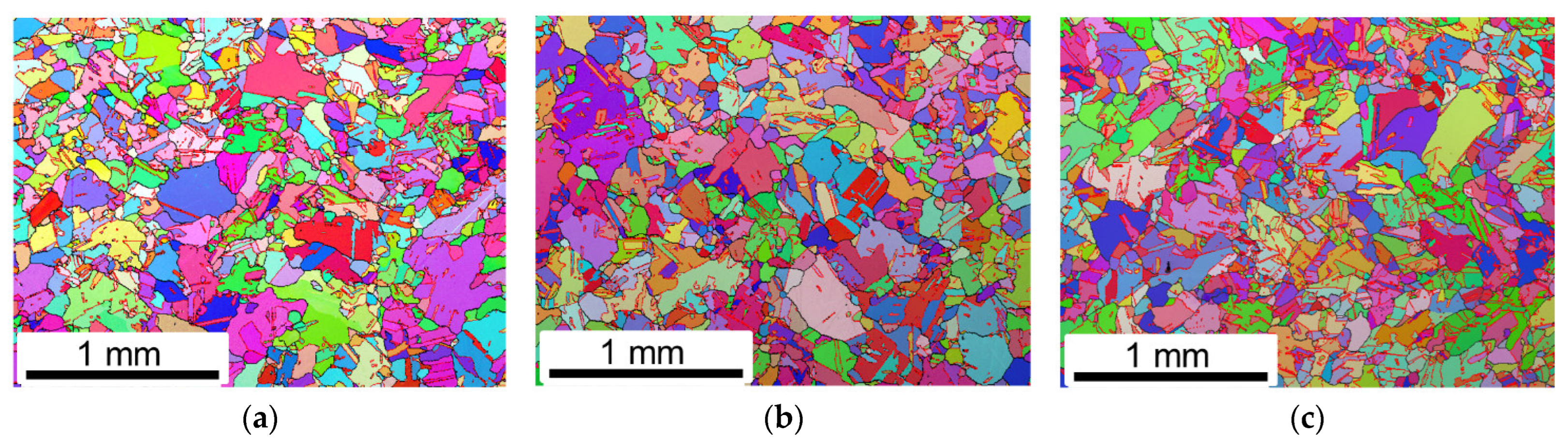
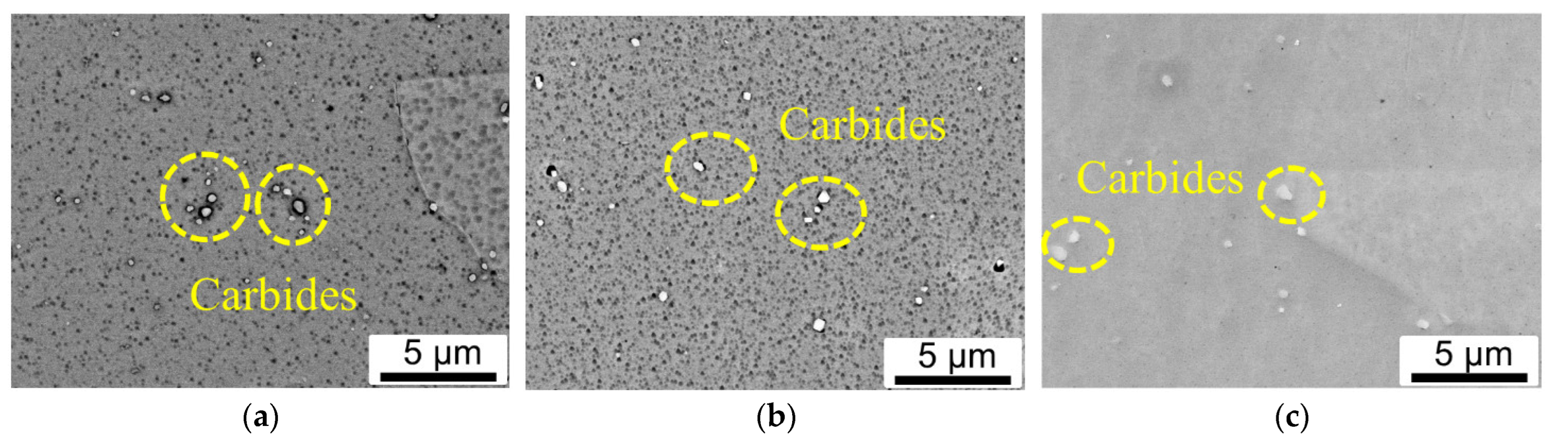
3.1. Microstructure Evolution
3.2. Creep Tests
3.3. Fracture Mechanism
4. Discussion
5. Conclusions
Author Contributions
Funding
Institutional Review Board Statement
Informed Consent Statement
Data Availability Statement
Conflicts of Interest
References
- Carroll, B.E.; Otis, R.A.; Borgonia, J.P.; Suh, J.O.; Dillon, R.P.; Shapiro, A.A.; Hofmann, D.C.; Liu, Z.K.; Beese, A.M. Functionally Graded Material of 304L Stainless Steel and Inconel 625 Fabricated by Directed Energy Deposition: Characterization and Thermodynamic Modeling. Acta Mater. 2016, 108, 46–54. [Google Scholar] [CrossRef]
- Kim, S.H.; Lee, H.; Yeon, S.M.; Aranas, C.; Choi, K.; Yoon, J.; Yang, S.W.; Lee, H. Selective Compositional Range Exclusion via Directed Energy Deposition to Produce a Defect-Free Inconel 718/SS 316L Functionally Graded Material. Addit. Manuf. 2021, 47, 102288. [Google Scholar] [CrossRef]
- Li, K.; Zhan, J.; Zhang, M.; Ma, R.; Tang, Q.; Zhang, D.Z.; Murr, L.E.; Cao, H. A Functionally Graded Material Design from Stainless Steel to Ni-Based Superalloy by Laser Metal Deposition Coupled with Thermodynamic Prediction. SSRN Electron. J. 2022, 217, 110612. [Google Scholar] [CrossRef]
- Džugan, J.; Melzer, D.; Koukolíková, M.; Vavřík, J.; Seifi, M. Characterization of Functionally Graded Materials Based on Inconel 718 and Stainless Steel 316L Manufactured by DED Process. Struct. Integr. Addit. Manuf. Mater. Parts 2020, 247–256. [Google Scholar] [CrossRef]
- Liang, X.; Wu, D.; Li, Q.; Jiang, L. Laser Rapid Manufacturing of Stainless Steel 316L/Inconel718 Functionally Graded Materials: Microstructure Evolution and Mechanical Properties. Int. J. Opt. 2010, 2010, 1–6. [Google Scholar] [CrossRef]
- Melzer, D.; Džugan, J.; Koukolíková, M.; Rzepa, S.; Vavřík, J. Structural Integrity and Mechanical Properties of the Functionally Graded Material Based on 316L/IN718 Processed by DED Technology. Mater. Sci. Eng. A 2021, 811, 141038. [Google Scholar] [CrossRef]
- Shah, K.; ul Haq, I.; Khan, A.; Shah, S.A.; Khan, M.; Pinkerton, A.J. Parametric Study of Development of Inconel-Steel Functionally Graded Materials by Laser Direct Metal Deposition. Mater. Des. 2014, 54, 531–538. [Google Scholar] [CrossRef]
- Xu, Z.; Murray, J.W.; Hyde, C.J.; Clare, A.T. Effect of Post Processing on the Creep Performance of Laser Powder Bed Fused Inconel 718. Addit. Manuf. 2018, 24, 486–497. [Google Scholar] [CrossRef]
- Brenne, F.; Taube, A.; Pröbstle, M.; Neumeier, S.; Schwarze, D.; Schaper, M.; Niendorf, T. Microstructural Design of Ni-Base Alloys for High-Temperature Applications: Impact of Heat Treatment on Microstructure and Mechanical Properties after Selective Laser Melting. Prog. Addit. Manuf. 2016, 1, 141–151. [Google Scholar] [CrossRef]
- Xu, Z.; Hyde, C.J.; Tuck, C.; Clare, A.T. Creep Behaviour of Inconel 718 Processed by Laser Powder Bed Fusion. J. Mater. Process. Technol. 2018, 256, 13–24. [Google Scholar] [CrossRef]
- Wang, L.Y.; Zhou, Z.J.; Li, C.P.; Chen, G.F.; Zhang, G.P. Comparative Investigation of Small Punch Creep Resistance of Inconel 718 Fabricated by Selective Laser Melting. Mater. Sci. Eng. A 2019, 745, 31–38. [Google Scholar] [CrossRef]
- Kuo, Y.L.; Nagahari, T.; Kakehi, K. The Effect of Post-Processes on the Microstructure and Creep Properties of Alloy718 Built up by Selective Laser Melting. Materials 2018, 11, 996. [Google Scholar] [CrossRef] [PubMed]
- Kuo, Y.L.; Horikawa, S.; Kakehi, K. Effects of Build Direction and Heat Treatment on Creep Properties of Ni-Base Superalloy Built up by Additive Manufacturing. Scr. Mater. 2017, 129, 74–78. [Google Scholar] [CrossRef]
- Danard, Y.; Lilensten, L.; Brozek, C.; Sun, F.; Vermaut, P.; Prima, F. Creep and Thermomechanical Fatigue of Functionally Graded Inconel 718 Produced by Additive Manufacturing. In Proceedings of the TMS 2018 147th Annual Meeting & Exhibition Supplemental Proceedings, Phoenix, AZ, USA, 11–15 March 2018; Volume 961. [Google Scholar] [CrossRef]
- Sanchez, S.; Hyde, C.J.; Ashcroft, I.A.; Ravi, G.A.; Clare, A.T. Multi-Laser Scan Strategies for Enhancing Creep Performance in LPBF. Addit. Manuf. 2021, 41, 101948. [Google Scholar] [CrossRef]
- McLouth, T.D.; Witkin, D.B.; Bean, G.E.; Sitzman, S.D.; Adams, P.M.; Lohser, J.R.; Yang, J.M.; Zaldivar, R.J. Variations in Ambient and Elevated Temperature Mechanical Behavior of IN718 Manufactured by Selective Laser Melting via Process Parameter Control. Mater. Sci. Eng. A 2020, 780, 139184. [Google Scholar] [CrossRef]
- Wang, L.Y.; Wang, Y.C.; Zhou, Z.J.; Wan, H.Y.; Li, C.P.; Chen, G.F.; Zhang, G.P. Small Punch Creep Performance of Heterogeneous Microstructure Dominated Inconel 718 Fabricated by Selective Laser Melting. Mater. Des. 2020, 195, 109042. [Google Scholar] [CrossRef]
- Pröbstle, M.; Neumeier, S.; Hopfenmüller, J.; Freund, L.P.; Niendorf, T.; Schwarze, D.; Göken, M. Superior Creep Strength of a Nickel-Based Superalloy Produced by Selective Laser Melting. Mater. Sci. Eng. A 2016, 674, 299–307. [Google Scholar] [CrossRef]
- Sanchez, S.; Gaspard, G.; Hyde, C.J.; Ashcroft, I.A.; Ravi, G.A.; Clare, A.T. The Creep Behaviour of Nickel Alloy 718 Manufactured by Laser Powder Bed Fusion. Mater. Des. 2021, 204, 109647. [Google Scholar] [CrossRef]
- Xu, Z.; Cao, L.; Zhu, Q.; Guo, C.; Li, X.; Hu, X.; Yu, Z. Creep Property of Inconel 718 Superalloy Produced by Selective Laser Melting Compared to Forging. Mater. Sci. Eng. A 2020, 794, 139947. [Google Scholar] [CrossRef]
- Li, Y.; Dlouhý, J.; Vavřík, J.; Džugan, J.; Konopík, P.; Krajňák, T.; Veselý, J. Investigation of Short-Term Creep Properties of a Coarse-Grained Inconel 718 Fabricated by Directed Energy Deposition Compared to Traditional Inconel 718. Mater. Sci. Eng. A 2022, 844, 143143. [Google Scholar] [CrossRef]
- Sun, S.H.; Koizumi, Y.; Kurosu, S.; Li, Y.P.; Chiba, A. Phase and Grain Size Inhomogeneity and Their Influences on Creep Behavior of Co-Cr-Mo Alloy Additive Manufactured by Electron Beam Melting. Acta Mater. 2015, 86, 305–318. [Google Scholar] [CrossRef]
- Li, Y.; Dlouhý, J.; Koukolíková, M.; Kirana, A.; Vavřík, J.; Džugan, J. Effect of Deposit Thickness on Microstructure and Mechanical Properties at Ambient and Elevated Temperatures for Inconel 718 Superalloy Fabricated by Directed Energy Deposition. J. Alloys Compd. 2022, 908, 164723. [Google Scholar] [CrossRef]
- Gallmeyer, T.G.; Moorthy, S.; Kappes, B.B.; Mills, M.J.; Amin-Ahmadi, B.; Stebner, A.P. Knowledge of Process-Structure-Property Relationships to Engineer Better Heat Treatments for Laser Powder Bed Fusion Additive Manufactured Inconel 718. Addit. Manuf. 2020, 31, 100977. [Google Scholar] [CrossRef]
- Liu, L.; Ding, Q.; Zhong, Y.; Zou, J.; Wu, J.; Chiu, Y.L.; Li, J.; Zhang, Z.; Yu, Q.; Shen, Z. Dislocation Network in Additive Manufactured Steel Breaks Strength–Ductility Trade-Off. Mater. Today 2018, 21, 354–361. [Google Scholar] [CrossRef]
- Yoo, Y.S.J.; Book, T.A.; Sangid, M.D.; Kacher, J. Identifying Strain Localization and Dislocation Processes in Fatigued Inconel 718 Manufactured from Selective Laser Melting. Mater. Sci. Eng. A 2018, 724, 444–451. [Google Scholar] [CrossRef]
- Voisin, T.; Forien, J.; Perron, A.; Aubry, S.; Bertin, N.; Samanta, A.; Baker, A.; Wang, Y.M.; Voisin, T.; Forien, J.; et al. New Insights on Cellular Structures Strengthening Mechanisms and Thermal. Acta Mater. 2020, 203, 116476. [Google Scholar] [CrossRef]
- Tucho, W.M.; Cuvillier, P.; Sjolyst-Kverneland, A.; Hansen, V. Microstructure and Hardness Studies of Inconel 718 Manufactured by Selective Laser Melting before and after Solution Heat Treatment. Mater. Sci. Eng. A 2017, 689, 220–232. [Google Scholar] [CrossRef]
- Ávila Calderón, L.A.; Rehmer, B.; Schriever, S.; Ulbricht, A.; Agudo Jácome, L.; Sommer, K.; Mohr, G.; Skrotzki, B.; Evans, A. Creep and Creep Damage Behavior of Stainless Steel 316L Manufactured by Laser Powder Bed Fusion. Mater. Sci. Eng. A 2022, 830, 142223. [Google Scholar] [CrossRef]
- Han, Y.; Chaturvedi, M.C. Steady State Creep Deformation of Superalloy Inconel 718. Mater. Sci. Eng. 1987, 89, 25–33. [Google Scholar] [CrossRef]
- Chaturvedi, M.C.; Han, Y. Creep Deformation of Alloy 718; Superalloy 718: Metallurgy and applications; The Minerals, Metals & Materials Society: Pittsburgh, PA, USA, 1989; pp. 489–498. [Google Scholar] [CrossRef]
- Cocks, A.C.F. The Nucleation and Growth of Voids in a Material Containing a Distribution of Grain-Boundary Particles. Acta Metall. 1985, 33, 129–137. [Google Scholar] [CrossRef]
- Chen, W.; Chen, M.C.C. Depedndence of Creep Fracture of Inconel 718 on Grain Boundary Precipitates. Acta Mater. 1997, 45, 2735–2746. [Google Scholar] [CrossRef]
- Sundararaman, M.; Mukhopadhyay, P.; Banerjee, S. Carbide Precipitation in Nickel Base Superalloys 718 and 625 and Their Effect on Mechanical Properties; Superalloys 718, 625, 706 and Various Derivatives; The Minerals, Metals & Materials Society: Pittsburgh, PA, USA, 1997; pp. 367–378. [Google Scholar] [CrossRef]


| Condition | Designation | 1st Step: Homogenization | 2nd Step: Aging Hardening |
|---|---|---|---|
| Homogenization heat treatment at 1080 °C | HA-1080 °C | 1080 °C/1 h/water cooling | 720 °C/8 h/furnace cooling 50 °C/h + 620 °C/8 h/air cooling |
| Homogenization heat treatment at 1180 °C | HA-1180 °C | 1180 °C/1 h/water cooling | |
| Hot isostatic pressing and double aging treatment | HIP-DA | 1180 °C/100 MPa/4 h |
| DA | Wrought | HA-1080 °C | HA-1180 °C | HIP-DA | |
|---|---|---|---|---|---|
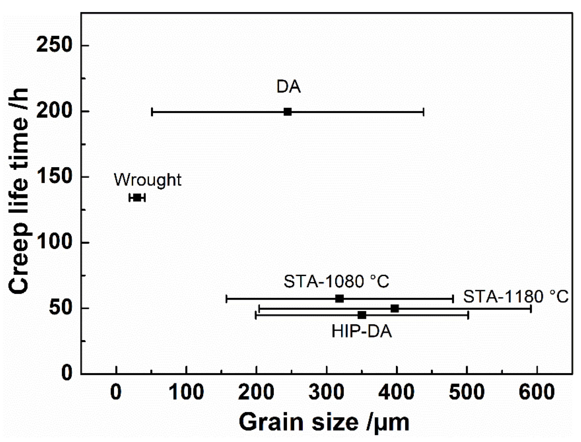
| tr/h | 200 ± 26 | 134 ± 36 | 57 ± 24 | 50 ± 7 | 45 ± 23 |
| ε˙min × 10−8/s−1 | 1.8 ± 0.1 | 2.2 ± 0.6 | 2.9 ± 0.3 | 3.2 ± 0.3 | 3.6 ± 0.2 |
| εf/% | 3.9 ± 0.1 | 3.5 ± 1.5 | 1.0 ± 0.5 | 1.0 ± 0.1 | 0.8 ± 0.4 |
Disclaimer/Publisher’s Note: The statements, opinions and data contained in all publications are solely those of the individual author(s) and contributor(s) and not of MDPI and/or the editor(s). MDPI and/or the editor(s) disclaim responsibility for any injury to people or property resulting from any ideas, methods, instructions or products referred to in the content. |
© 2023 by the authors. Licensee MDPI, Basel, Switzerland. This article is an open access article distributed under the terms and conditions of the Creative Commons Attribution (CC BY) license (https://creativecommons.org/licenses/by/4.0/).
Share and Cite
Li, Y.; Podaný, P.; Koukolíková, M.; Džugan, J.; Krajňák, T.; Veselý, J.; Raghavan, S. Effect of Heat Treatment on Creep Deformation and Fracture Properties for a Coarse-Grained Inconel 718 Manufactured by Directed Energy Deposition. Materials 2023, 16, 1377. https://0-doi-org.brum.beds.ac.uk/10.3390/ma16041377
Li Y, Podaný P, Koukolíková M, Džugan J, Krajňák T, Veselý J, Raghavan S. Effect of Heat Treatment on Creep Deformation and Fracture Properties for a Coarse-Grained Inconel 718 Manufactured by Directed Energy Deposition. Materials. 2023; 16(4):1377. https://0-doi-org.brum.beds.ac.uk/10.3390/ma16041377
Chicago/Turabian StyleLi, Ying, Pavel Podaný, Martina Koukolíková, Jan Džugan, Tomáš Krajňák, Jozef Veselý, and Srinivasan Raghavan. 2023. "Effect of Heat Treatment on Creep Deformation and Fracture Properties for a Coarse-Grained Inconel 718 Manufactured by Directed Energy Deposition" Materials 16, no. 4: 1377. https://0-doi-org.brum.beds.ac.uk/10.3390/ma16041377