
A Calculation Method for Tooth Wear Depth Based on the Finite Element Method That Considers the Dynamic Mesh Force


State Key Laboratory of Mechanical Transmission, Chongqing University, Chongqing 400044, China
*
Author to whom correspondence should be addressed.
Machines 2022, 10(2), 69; https://0-doi-org.brum.beds.ac.uk/10.3390/machines10020069
Submission received: 17 December 2021
/
Revised: 12 January 2022
/
Accepted: 13 January 2022
/
Published: 18 January 2022
(This article belongs to the Section Machines Testing and Maintenance)
Abstract
:Gear wear is a progressive material removal process that gradually changes the tooth profile shape and dynamic mesh force, where the dynamic mesh force affects the tooth surface wear. To describe this process, a spur gear dynamic model that includes the mesh stiffness and unloaded static transmission error (STE) of the worn tooth profile is proposed for calculating the dynamic mesh force. Then, based on the finite element method (FEM), a dynamic contact analysis model that considers the dynamic mesh force is proposed for calculating the time-varying contact stress and relative sliding distance of the tooth surface mesh point. Finally, combined with the Archard wear model, a tooth wear depth calculation method that considers the worn tooth profile and the dynamic mesh force is proposed. In addition, the wear depth and dynamic characteristics under different wear times are studied.
1. Introduction
Gear transmission devices are widely used in the field of mechanical engineering because of their high transmission efficiencies, stable transmission ratios, compact structures and long service lives [1,2,3]. During the working process, the two contact tooth surfaces slide relatively, which leads to tooth surface wear. Gear wear is a gradual material removal process that gradually changes the tooth profile shape and dynamic mesh force. Excessive gear wear not only reduces the transmission efficiency and accuracy but also aggravates the vibration and noise of the system [4]. Therefore, gear wear has attracted much attention in recent years [5]. There are two ways to study the wear depth of the tooth surface: experiments [6,7,8] and numerical simulations [9,10,11,12,13,14]. The wear data measured by experiments are often only a macro total, making it difficult to elucidate the details of gear profile wear. In addition, such experiments are time-consuming and costly. Therefore, the numerical simulation method is the most popular method for studying gear wear.
Archard’s wear theory [15], as the most prevailing method for wear prediction, is widely applied in studies of tooth surface wear. The key points for accurately calculating the tooth surface wear depth with Archard’s wear theory [15] include the accurate calculation of the wear coefficient, tooth surface contact stress and relative sliding distance. There are two typical methods for calculating the contact stress and relative sliding distance of the tooth surface: the analytical method [9,10,11,14,16,17] and the finite element method (FEM) [18,19,20,21,22]. A. Flodin et al. [9] proposed a load distribution equation for obtaining the transmitted load between two tooth pairs, used Hertz’s theory [23] to calculate the contact stress, and used the single point observation method proposed by Andersson [24] to calculate the relative sliding distance. Finally, the calculation method for the wear depth of the spur gear tooth surface was defined and combined with Archard’s wear model [15]. Inspired by A. Flodin, some scholars extended Flodin’s model to the wear prediction of helical gears [10,11], planetary gears [13,25,26], asymmetric gears [27], internal gears [17], hypoid gears [16,28,29], and double helical gears [30]. These analytical methods can efficiently predict the wear evolution, but their the accuracy must be improved, especially for gear teeth with irregular profile errors [31].
Compared to analytical methods, FEM can compute gear wear with more reasonable accuracy [32,33]. Based on the FEM, V. Hegadekatt et al. [19,21] proposed a wear calculation method that can update the contact surface geometry; this method was applied to the calculation of the tooth surface wear depth of a microgear. P. Bajpai and A. Kahraman [18] used the FEM to calculate the tooth surface contact stress and proposed coordinate-based methods to obtain the relative sliding distance, thus forming a new tooth surface wear depth calculation method for axis gear pairs. Later, D. Park and A. Kahraman [20] extended this method to calculate the wear depth of hypoid gear pairs. J. Zhang et al. [22] used the FEM to calculate the tooth surface contact stress, integrated the relative sliding speed with time to calculate the relative sliding distance, and then studied the influence of misalignment on tooth surface wear. However, these wear prediction models were based on the quasi-static assumption.
Recently, more sophisticated models that can take the dynamic load into consideration have been proposed. Huali Ding and A. Kahraman [4] calculated the dynamic load on the tooth surface by the dynamic gear pair model and then combined it with the tooth surface wear calculation method proposed by P. Bajpai and A. Kahraman [18] to study the influence of the tooth surface wear depth on spur gear dynamics. Inspired by Ding and Kahraman, some scholars [12,34,35,36,37] combined the dynamic analysis method with the different wear depth calculation methods mentioned above to form different wear depth calculation methods that consider the dynamic load. However, these wear depth calculation methods assume that the contact stress and relative sliding distance of each mesh point on the tooth surface are constant in each single wear cycle. That is, the time-varying characteristics of the tooth surface contact stress and relative sliding distance are not considered, which may decrease the prediction accuracy of the wear depth calculation. In addition, there is little research on the calculation method of the wear coefficient of gear materials.
This paper is devoted to developing a wear depth calculation method that can consider the dynamic load, time-varying contact stress and relative sliding distance. In addition, a method is proposed for calculating the wear coefficient.
2. Materials and Methods
2.1. Materials and Gear Parameters
In order to illustrate the calculation method of material wear coefficient proposed in this paper, 20CrMoH steel is taken as an example. The chemical composition of 20CrMoH material are shown in Table 1.
2.2. Methods
2.2.1. Archard’s Wear Model
Archard’s wear model is a simple phenomenological model that assumes a linear relationship between the volume of material removed , for a given sliding distance , an applied normal load and the hardness of the softer material . A proportionality constant, the wear coefficient , characterizes the wear resistance of the material:
To apply Archard’s wear model to the calculation of wear depth for a complex contact surface, Archard’s wear model can be written in the differential time form:
where is the wear depth in the time period, is the relative sliding speed of the two contact surfaces of the gear at time , is the contact stress at time , and is the relative sliding distance in the time period.
2.2.2. Pin-On-Disc Wear Test and Wear Coefficient Calculation
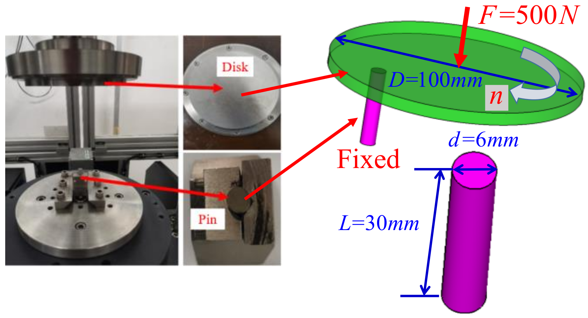
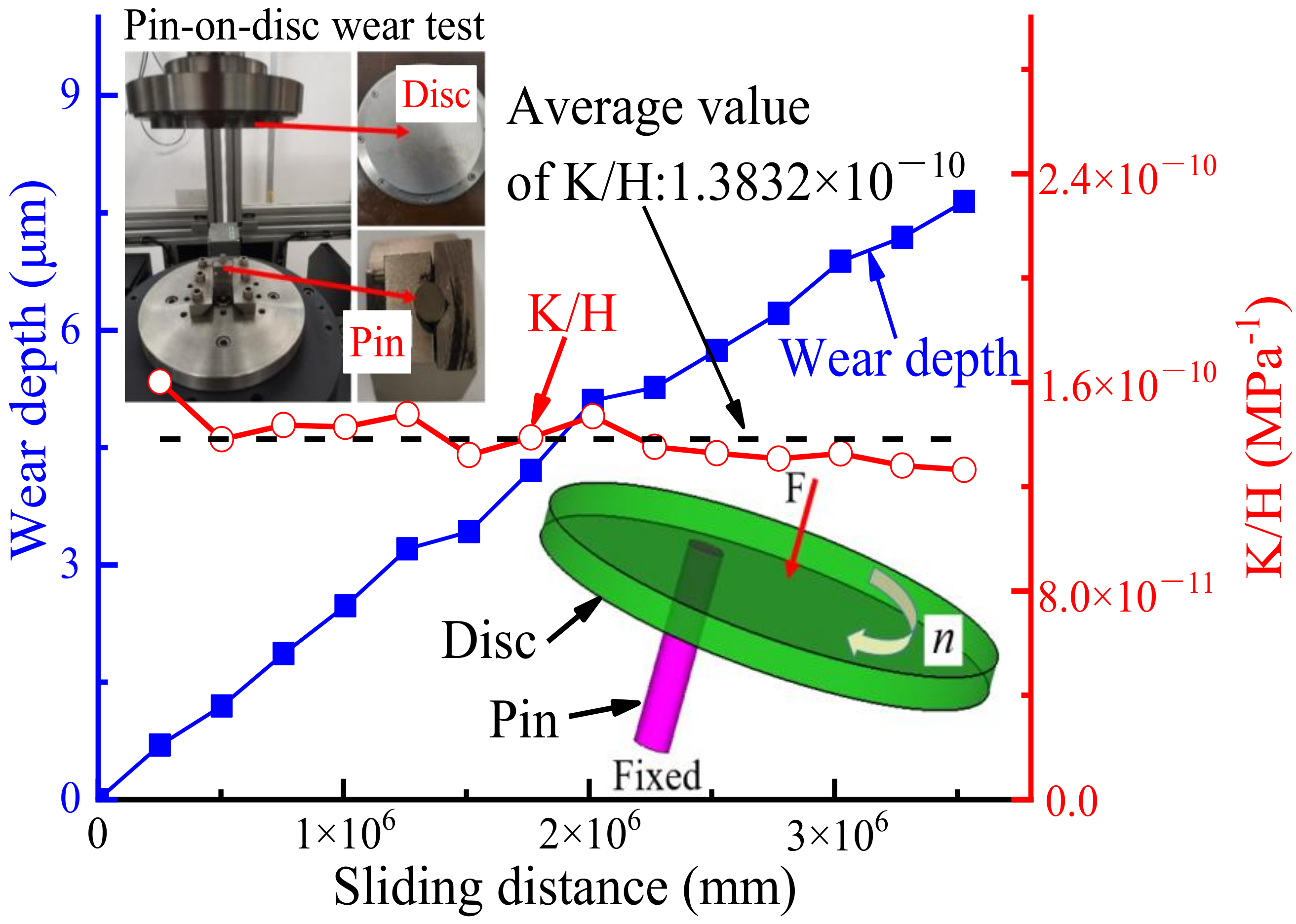
To obtain the wear coefficient K/H in Archard’s wear model, the pin-on-disc wear test of steel 20CrMoH was carried out on a Wazau TRM1000 wear tester. The test principle of the Wazau TRM1000 tester is to make the wear test material into a cylindrical pin with a diameter of 6 mm and a disc with a diameter of 100 mm. During the test, the pin is fixed on one side of the disc (not the center of the disc), the disc is pressed onto the pin through a certain normal load F (where F = 500 N) and the disc is rotated at a certain speed n. During the disc rotation, the wear depth is measured as the displacement perpendicular to the disc surface. The Pin-On-Disc wear test principle and test sample diagram are shown in Figure 1.
Assuming that the contact area and contact stress remain unchanged during the pin-on-disc wear test, Equation (2) can be analyzed as:
where s is the cross-sectional area of the pin, is the normal load, is the wear depth in the time period, and is the relative sliding distance in the time period.
2.2.3. Wear Calculation Method Based on the FEM and Simulation of Pin-On-Disc Wear Test
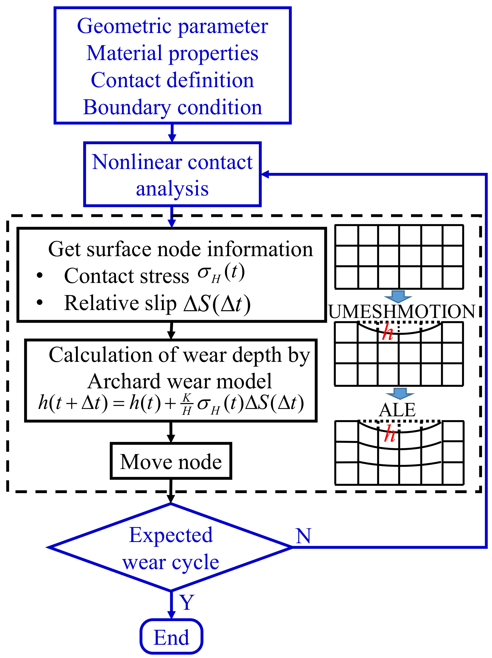
The wear process is a process of gradual material removal. With increased material removal, the geometry of the contact surface changes. To describe this process, the user-subroutine UMESHMOTION of ABAQUS is used to move the surface nodes to simulate the geometric update to the contact surface after wear. In the wear simulation calculation process, a nonlinear contact FEM model is established to calculate the contact stress and relative sliding distance. The Archard wear model is written as user-subroutine UMESHMOTION to calculate the wear depth of the surface nodes. The node at the contact surface is moved along the normal direction through the user-subroutine UMESHMOTION, where the moving distance is the wear depth. While the nodes are in motion, the arbitrary Lagrangian Eulerian (ALE) adaptive remesh algorithm is used to update the surface mesh to ensure the mesh quality. The nonlinear contact analysis is carried out again for the FEM model after the node has been moved. The nonlinear contact analysis and wear depth calculation are carried out again to form a feedback loop between the wear calculation and geometric update. After reaching the expected wear cycle, the calculation is stopped. The specific wear calculation process is shown in Figure 2.
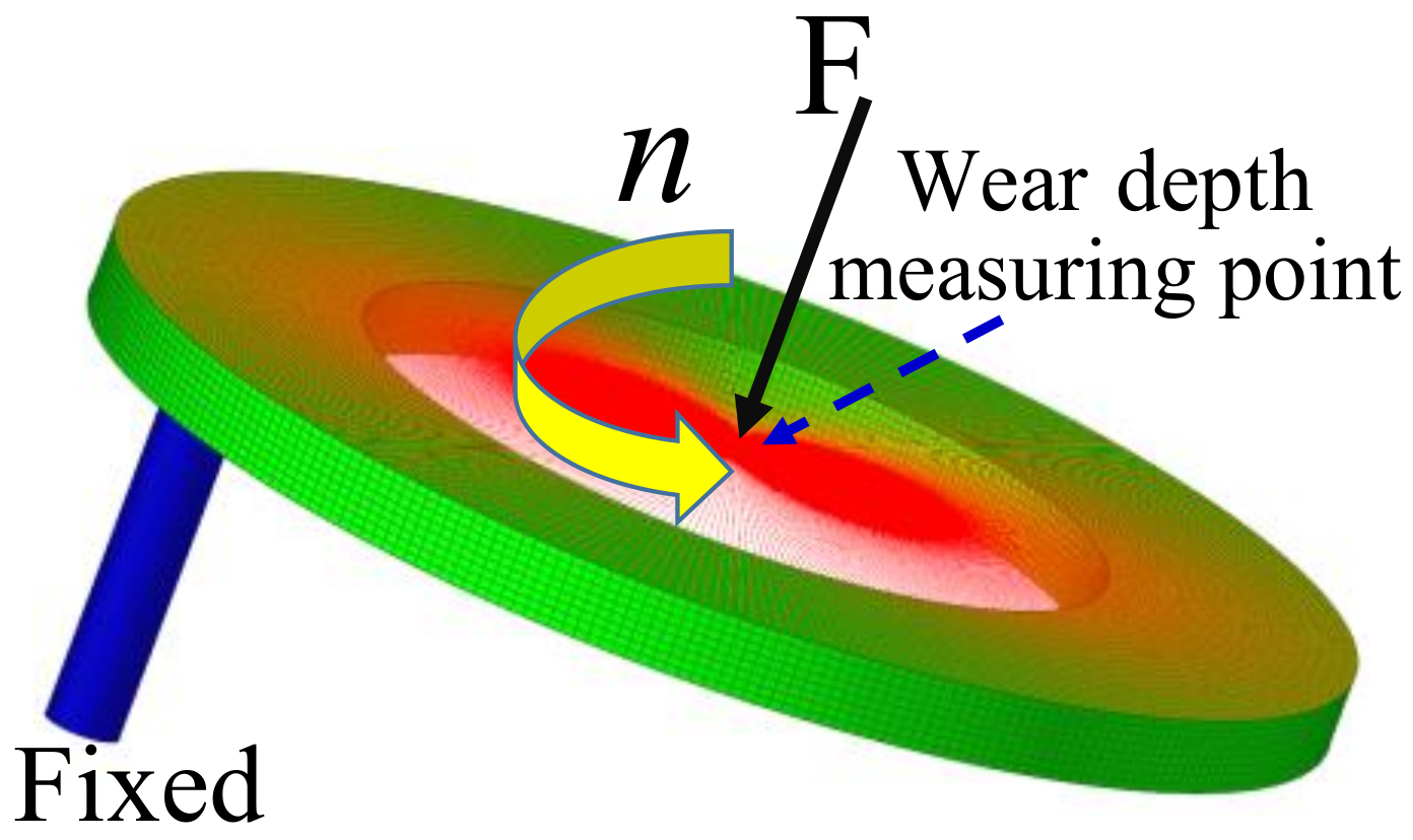
According to the pin-on-disc wear test conditions, the FEM model shown in Figure 3 can be established. The load F is applied first, and then the rotating speed n is applied. During the disc rotation, the normal displacement at the loading point is taken as the wear depth and compared to the test results.
2.2.4. Dynamic Model and Dynamic Mesh Force Calculation
The difference between tooth surface wear and pin-on-disc test wear is that the pin and disc always remain in contact during pin disc wear, and the normal load remains unchanged. In the tooth surface wear process, the contact state and load of each mesh point change with time. Therefore, to accurately calculate the wear depth throughout the mesh point, it is necessary to study the dynamic contact stress and relative sliding distance of each mesh point.
To accurately calculate the dynamic contact stress and relative sliding distance in the mesh process, it is necessary to calculate the dynamic mesh force in the mesh process. In this study, the spur gear dynamic models of [39,40] were adapted to calculate the dynamic mesh force.
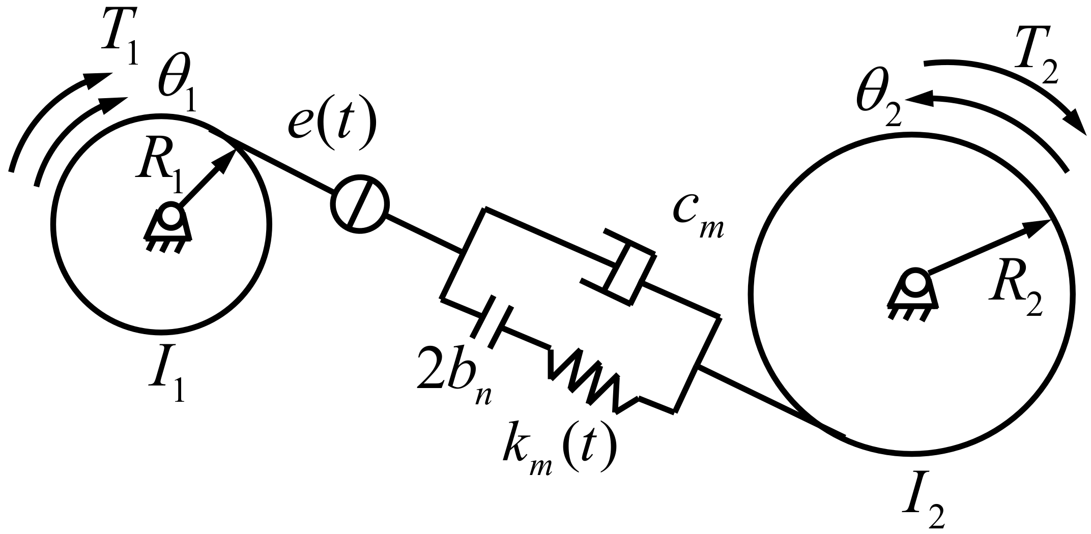
The spur dynamic model is shown in Figure 4. and are the rotation angles of the pinion and gear, respectively; and are the rotary inertias of the pinion and gear, respectively; and are the torques of the pinion and gear, respectively; and are the base circle radii of the pinion and gear, respectively; is the viscous damping in the gear mesh; is the unloaded static transmission error (STE), which is caused by tooth modification, manufacturing error or tooth wear; and is the backlash.
The equations of the spur gear dynamical model can be expressed as:
where an overdot denotes differentiation with respect to time ; is the dynamic transmission error (DTE) along the line of action; and is a function of backlash.
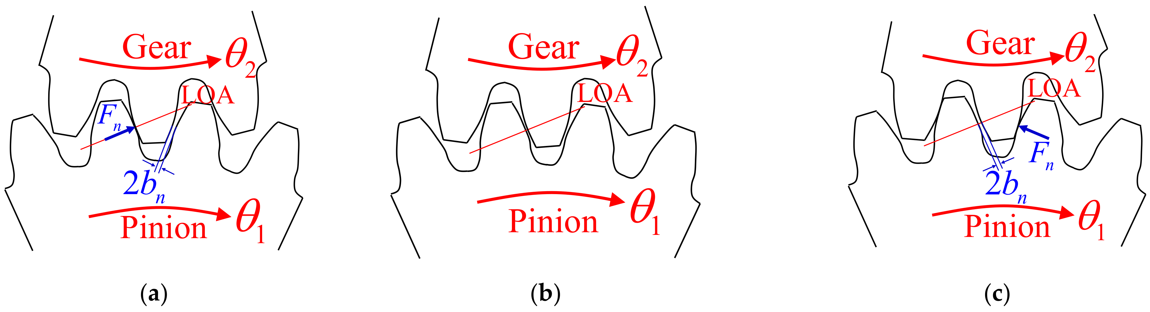
Due to the existence of gear backlash, different mesh states may occur during gear meshing, as shown in Figure 5 (where it is assumed that the pinion and gear are in contact at the initial time, but there is no contact force). In Figure 5, is the gear backlash.
The function of backlash in Equations (4) and (5) can be expressed as:
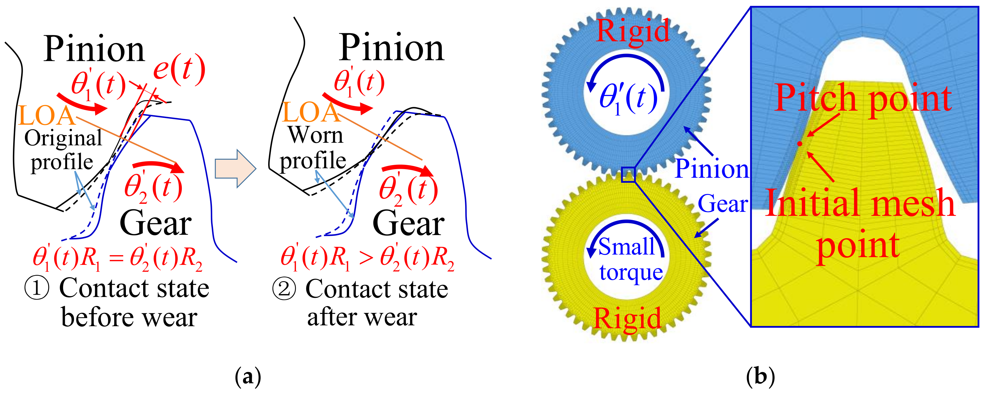
Since tooth modification and manufacturing error are not included in the present model, when the tooth surface is not worn, . When the tooth surface is worn, the tooth profile shape changes, and the contact position also changes even if the pinion and gear are not deformed under a load, as shown in Figure 6a. Due to the wear of the tooth surface, the pinion needs to rotate an additional angle so that the pinion and gear can remain in contact; this is the unloaded STE e(t) caused by tooth surface wear. To calculate the unloaded STE caused by wear, an FEM model, as shown in Figure 6b, is established according to the tooth profile after wear. Similar to [41], since the model is used only to calculate the unloaded STE, which does not need to consider the gear deformation, the pinion and gear are set as rigid bodies. The rotation angle is applied on the pinion, and a small torque is applied on the gear so that the gear remains in contact with the pinion without deformation. To capture the nature of tooth flank involute, elements near tooth flanks are further refined, and sizes of contact elements are controlled at 0.05 mm. Then, the unloaded STE can be expressed by Equation (7).
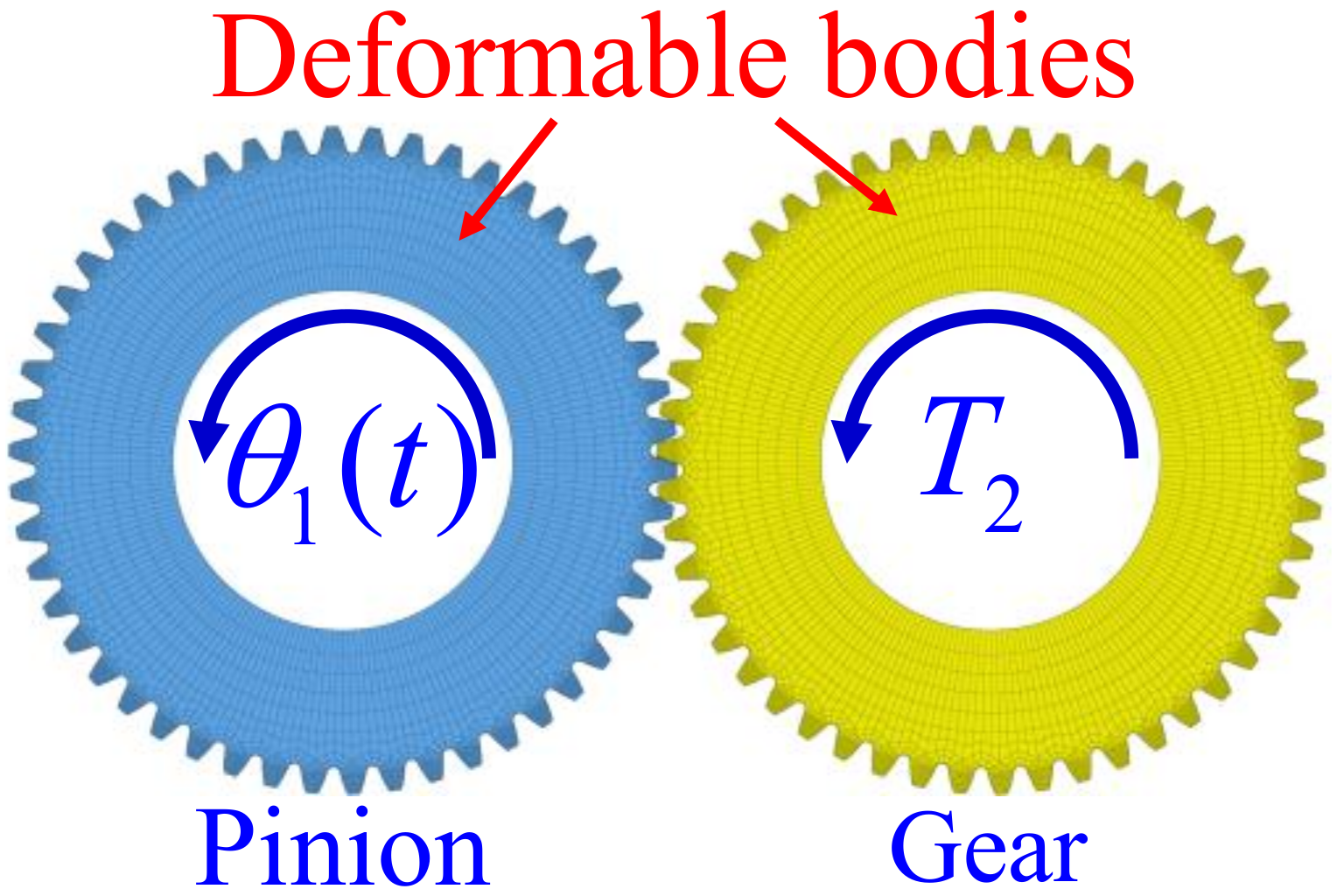
Mesh stiffness is calculated by dividing the mesh force by the mesh deflection [42]. To calculate the mesh stiffness, the rigid bodies in the FEM model for calculating the unloaded STE are changed to deformable bodies, and the small torque is changed to working torque, as shown in Figure 7. The mesh stiffness can then be calculated by Equation (8).
Upon multiplying Equation (4) by and Equation (5) by , Equations (4) and (5) can be written as:
For gear transmission, , Equation (9) is subtracted from Equation (10):
Let , then Equation (11) can be expressed as:
The DTE can be obtained by solving Equation (12) through the 4–5th order Runge-Kutta method (RK45). Similar to [39], the viscous damping is calculated by damping ratio through Equation (13), and the value of the damping ratio is 0.03.
where is the average mesh stiffness.
To realize the jump-up and jump-down-type nonlinear phenomena due to tooth separation, A. Kahraman et al. [38] carried out experiments on spur gears and measured the equivalent root-mean-square (rms) amplitude of the DTE. This equivalent DTE is computed based on the first three mesh harmonic amplitudes according to Equation (14) under both speed-up and speed-down conditions within a range of 500–4500 r/min.
where is the equivalent root-mean-square amplitude of the DTE and is the r-th mesh harmonic amplitude of the DTE.
To capture jump-up and jump-down type nonlinear phenomena as in the experiments, simulations were repeated for both speed-up and speed-down conditions within a range of 500 to 4500 r/min. Similar to [43], the last simulation point of the steady state motion from the previous speed was considered as the initial condition for the next speed (speed up or speed down) that followed. The last part of steady-state data of each speed was Fourier transformed to obtain the harmonic amplitude. Then, according to Equation (14), the equivalent root-mean-square amplitude of the DTE of each speed could be obtained.
After the DTE is calculated according to Equation (12), the dynamic mesh force of the tooth surface can be calculated with Equation (15).
2.2.5. Dynamic Contact Analysis Model and Theoretical Calculation Method
To accurately calculate the dynamic contact stress and relative sliding distance of the tooth surface required for wear calculation, this section proposes a calculation model for the tooth surface dynamic contact stress and relative sliding distance considering the dynamic mesh force based on the FEM and verifies the calculation results.
- 1.
- Dynamic contact analysis model based on FEM;
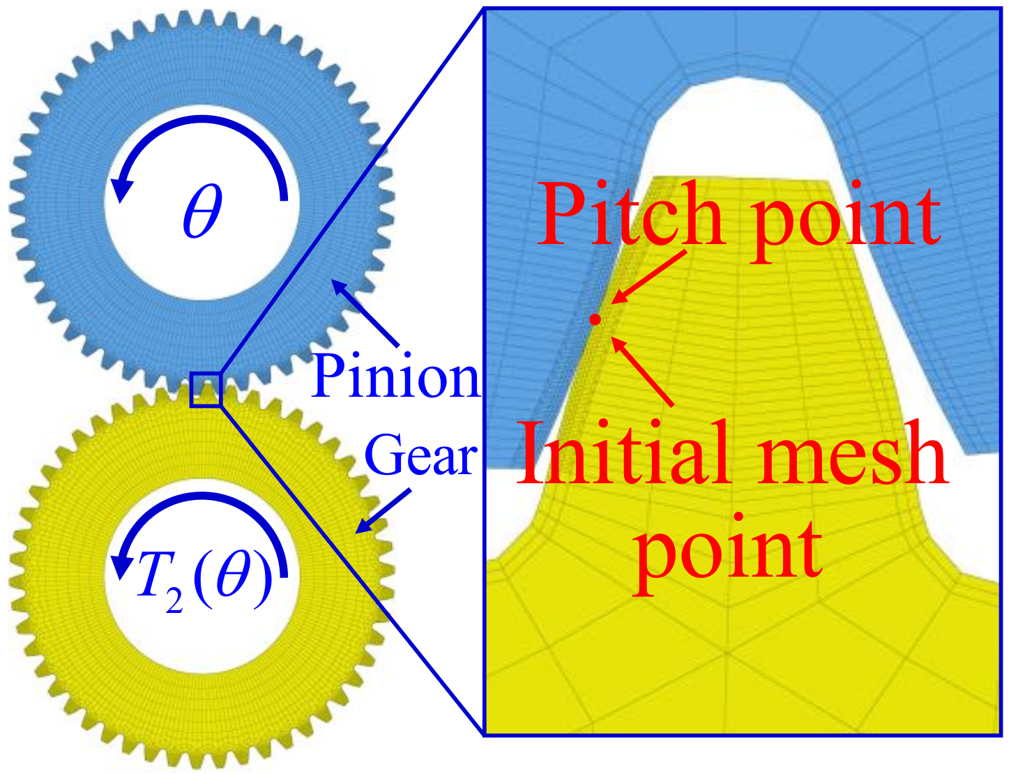
Similar to A. Flodin et al. [4,9,10,11,19,20,21,44], it is assumed that the mesh process of each tooth surface is the same; therefore, in this paper, one tooth surface is selected to study the gear meshing process. Considering the dynamic mesh force of the pinion in two mesh cycles as the research object, the dynamic mesh force of the two cycles is converted into the gear’s dynamic torque according to Equation (16). Here, one mesh cycle refers to the mesh process from one pitch point of the pinion to the next, and the corresponding rotation angle is 360°/50 = 7.2°. In the two mesh cycles, the pinion has three tooth surfaces involved in the mesh, and the meshing of the second tooth surface is a complete meshing process that includes engaging in and engaging out. A nonlinear contact FEM model, as shown in Figure 8, is established based on the dynamic torque. In this model, the rotation angle is applied to the pinion, and the dynamic torque that varies with the rotation angle is applied on the gear. Through the calculation of the FEM model, the dynamic mesh force, contact stress and relative sliding distance of the tooth surface can be obtained for each mesh point.
- 2.
- Max contact stress calculation based on Hertz theory
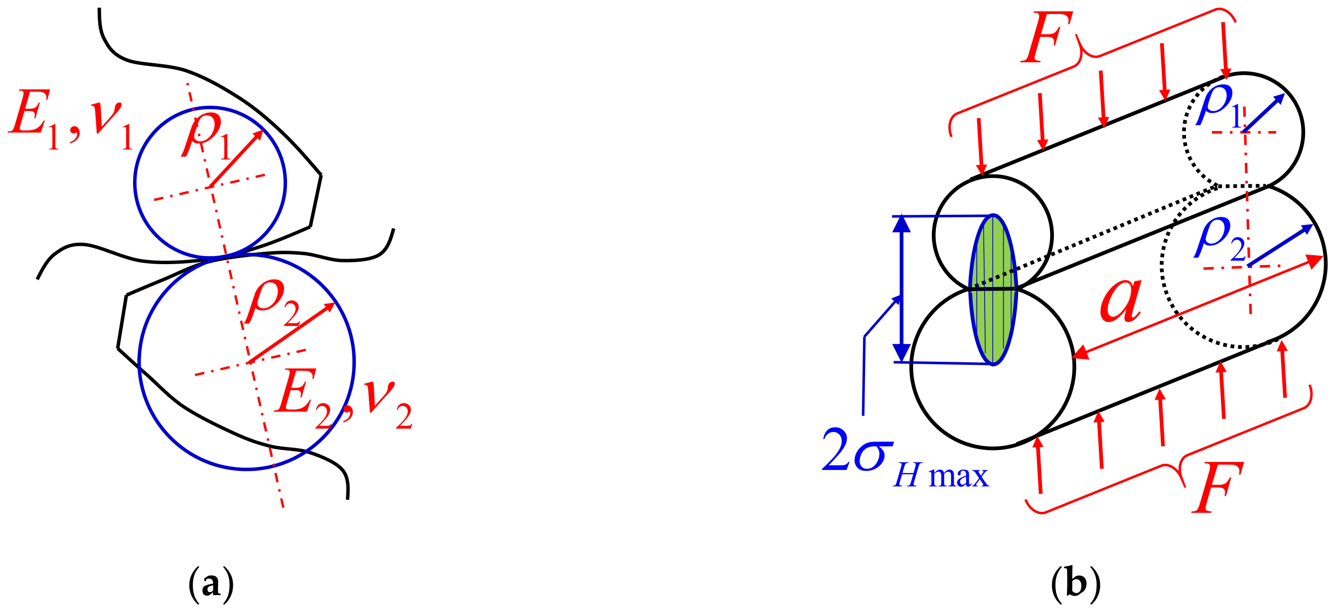
For spur gears, the contact of each mesh point on the tooth surface can be simplified to two cylindrical contact models with different radii (as shown in Figure 9a). According to Hertz theory, when two cylinders with radii and are in contact under a normal load F (as shown in Figure 9b), the maximum contact stress and half Hertz contact width of the two cylinders can be calculated based on Equation (17) and Equation (18), respectively.
where is the length of the cylinder.
where and are the elastic coefficients of the material, which can be calculated based on the elastic modulus and Poisson’s ratio of the material.
where and are the Poisson’s ratios and and are the elastic moduli.
- 3.
- Max relative sliding distance calculation based on single point observation method
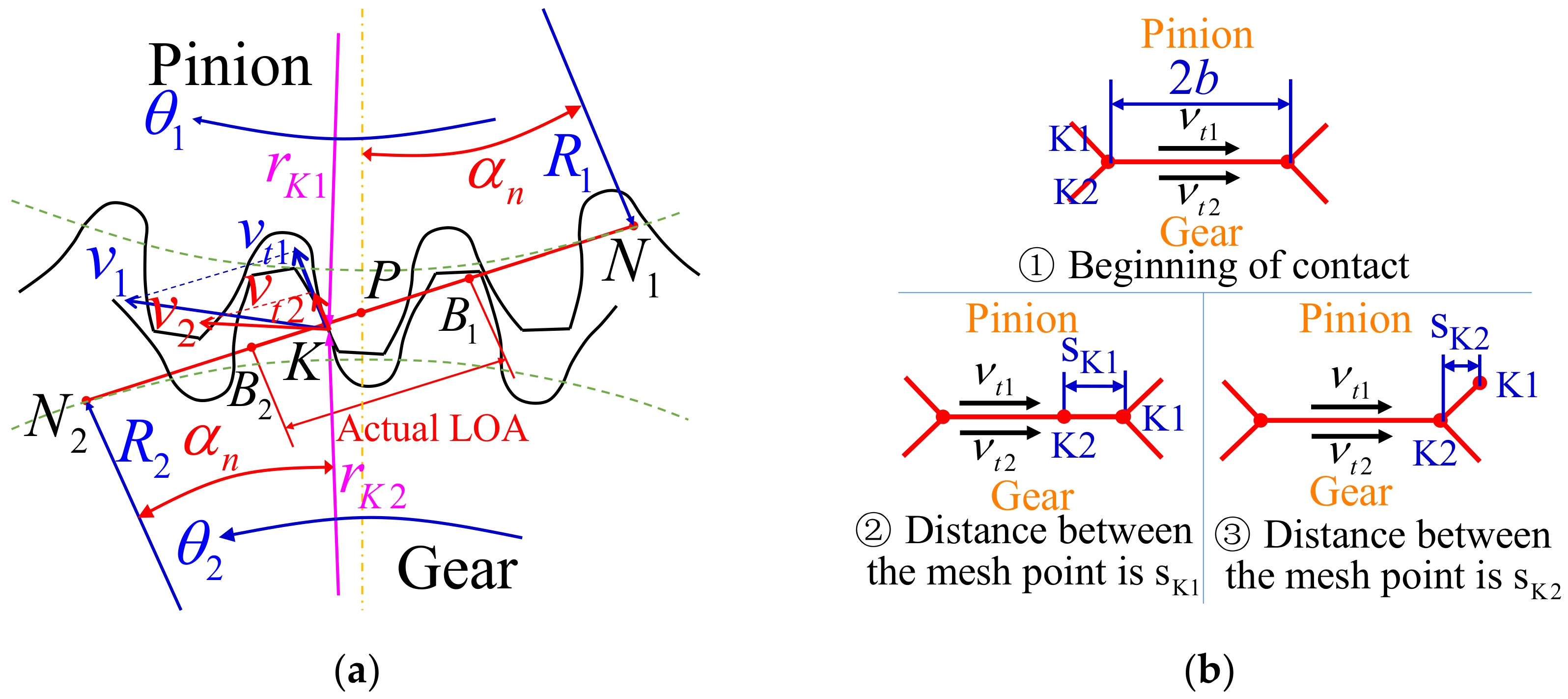
To comprehensively describe the gear mesh process, the mesh process for mesh point on the pinion and mesh point on the gear at point on the line of action (LOA) is analyzed. This meshing process is shown in Figure 10. According to Figure 10a, the tooth profile radius at point on the pinion is , the speed of point along the tangential direction of the tooth profile is vt1, the tooth profile radius at point on the gear is and the speed of point along the tangential direction of the tooth profile is vt2. According to Hertz theory, the contact width for mesh points and is ( is half Hertz contact width). Therefore, mesh points and need to move a distance of to separate, as shown in Figure 10b. When point K1 moves along the tangential direction of the tooth profile, point will move . Similarly, when point moves along the tangential direction of the tooth profile, point K1 will move . Therefore, the relative sliding distances and of mesh points and are:
where .
2.2.6. Wear Calculation Method for the Gear Surface
To accurately calculate the wear depth of the tooth surface, the dynamic contact analysis model of the tooth surface proposed in Section 2.2.5 is combined with the wear calculation method. This method can be used to update the geometry of the worn contact surface based on the FEM proposed in Section 2.2.3 to form a tooth surface wear depth calculation method that considers the dynamic load of the tooth surface and the shape of the worn tooth profile.
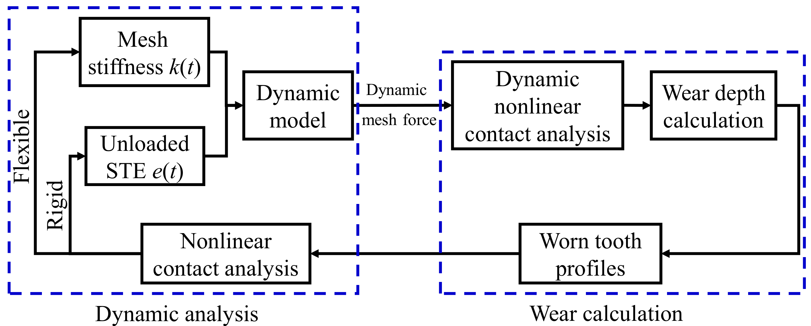
First, the mesh stiffness and unloaded STE of the gear are calculated by the FEM, and then the spur gear dynamic model is established to calculate the dynamic mesh force of the gear surface. Second, the dynamic contact FEM model proposed in Section 2.2.5 is established to calculate the dynamic contact stress and relative sliding distance of the tooth surface. Third, the wear calculation method, which can be used to update the geometry of the wear contact surface proposed in Section 2.2.3, is used to calculate the tooth surface wear depth and obtain the worn tooth profile. Finally, the mesh stiffness and unloaded STE of the gear are calculated again, and the dynamic model is established to calculate the dynamic mesh force; this forms a feedback loop between the tooth surface wear and the dynamic mesh force. A calculation method for tooth surface wear considering the dynamic load is defined. The calculation flow for the tooth surface wear is shown in Figure 11.
In contrast to the traditional wear depth calculation method, the time-varying contact stress and relative sliding distance of the mesh point are used to calculate the wear depth. The wear depth calculation equation is shown in Equation (23). Traditionally, it is difficult to obtain the time-varying contact stress and relative sliding distance from each mesh point with Hertz theory. Therefore, Huali Ding et al. [4,35,45] used the maximum contact stress and maximum relative sliding distance on each mesh point of the tooth surface to calculate the wear depth. The wear depth calculation equation is shown in Equation (24).
3. Results and Discussion
3.1. Pin-On-Disc Wear Test and Wear Coefficient Calculation Result
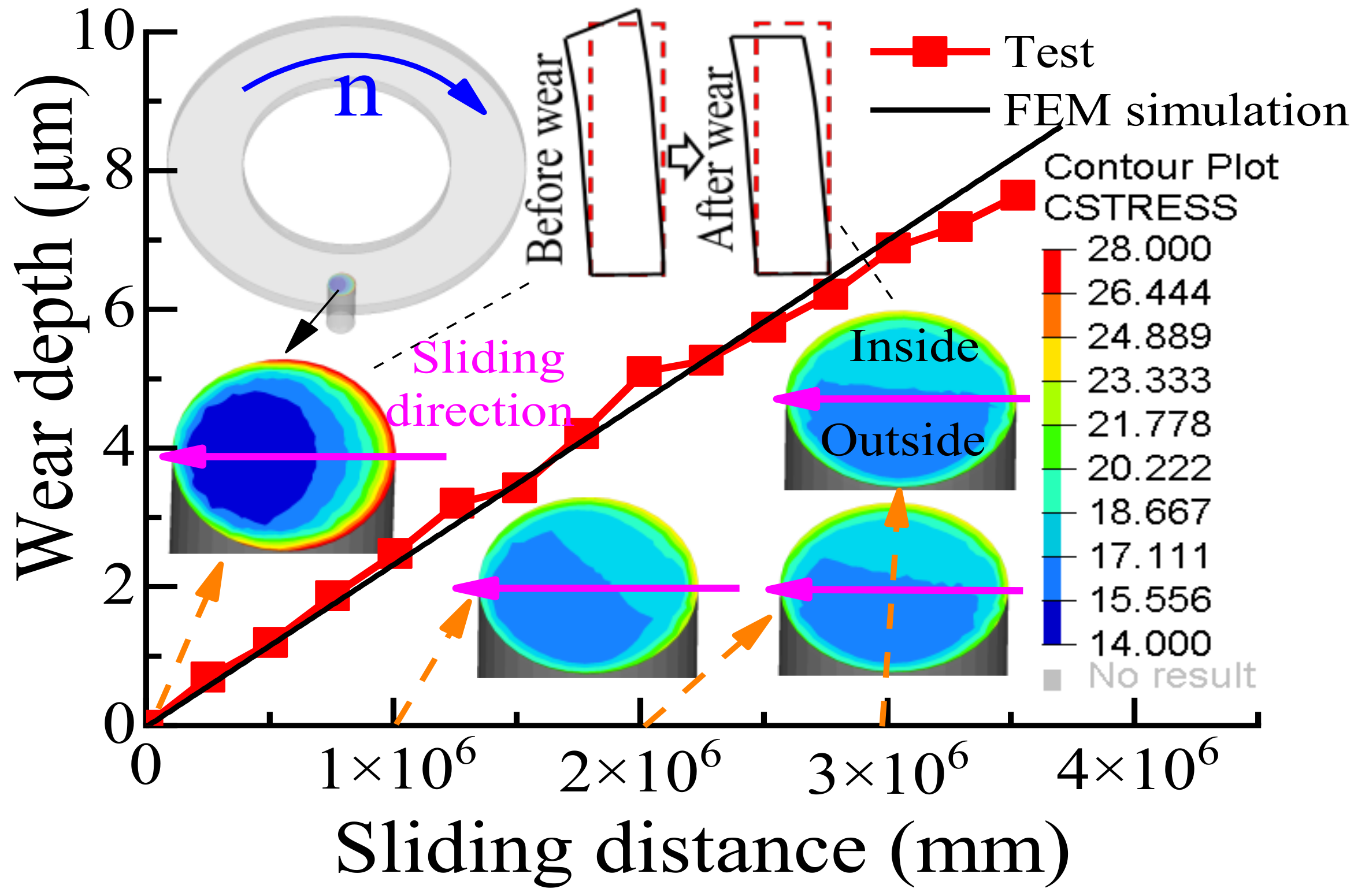
The curve of the wear depth and sliding distance measured for steel 20CrMoH is shown in Figure 12.
3.2. Simulation Result of Pin-On-Disc Wear Test
The contour plot of contact stress with different relative sliding distances and the calculated wear depth curve are shown in Figure 13.
Figure 13 shows that before the pin is worn, the pin bends due to the action of friction. Therefore, the contact stress of the pin before wear is larger on one side than the other. However, with the increase in wear, the contact stress gradually becomes uniform, and the maximum contact stress decreases to near the theoretical contact stress of 17.68 MPa. In addition, since the load is applied to the center of the disc, the contact stress of the pin close to the center of the disc is slightly greater than that away from the center of the disc. Finally, the wear depth obtained by the FEM simulation is consistent with the experimental results, confirming that the wear depth calculation method based on the FEM is feasible and that the wear coefficient obtained by the pin-on-disc wear test is reasonable.
3.3. Dynamic Analysis Result
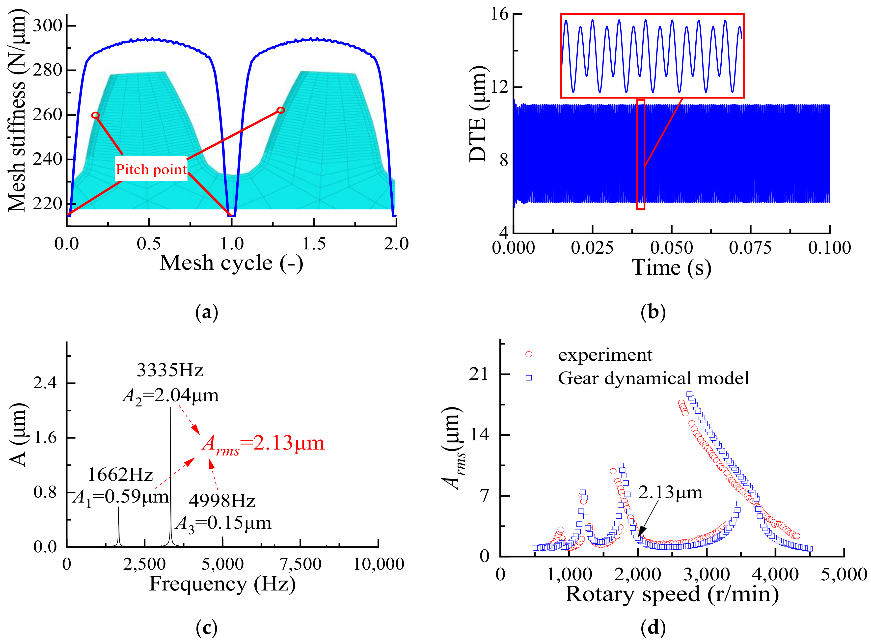
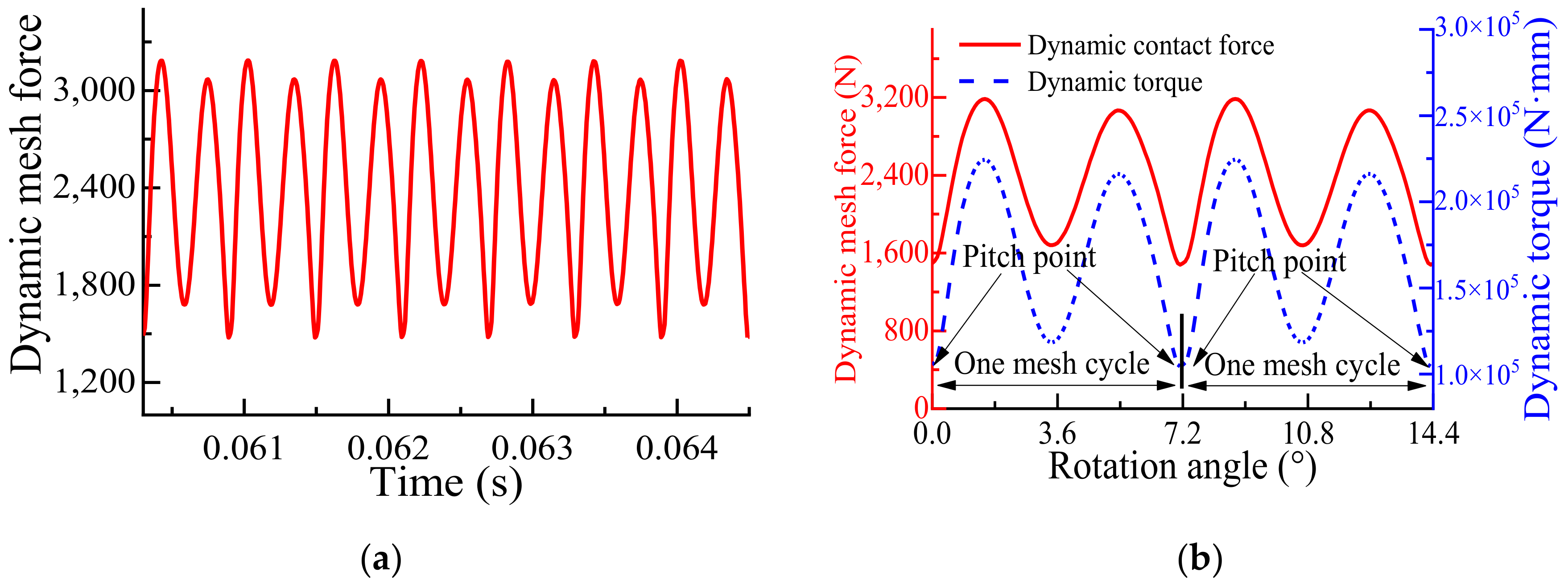
The mesh stiffness calculation results of the pair of gears are shown in Figure 14a. The DTE at the speed of 2000 r/min is shown in Figure 14b, the harmonic amplitude of the DTE is shown in Figure 14c, and the comparison between the equivalent root-mean-square amplitude of the DTE with different speeds calculated by the gear dynamics model and the experimental results is shown in Figure 14d. The dynamic mesh force is shown in Figure 15a. The dynamic mesh force and dynamic torque in the two mesh cycles are shown in Figure 15b.
Figure 14d shows that the predictions of the spur gear dynamic model match the measured data very well in terms of both the overall amplitudes and the shape of the forced response. The measured primary resonance near 3500 r/min and the first two superharmonic resonances near 1750, 1167 and 875 r/min are predicted accurately by the spur gear dynamic model. The amplitudes of the DTE are also predicted accurately in both the resonance and off-resonance regions. In addition, the measured nonlinear behavior characterized by a frequency range of dual stable motions (a lower branch no-contact-loss motion and an upper branch tooth-separation motion) bounded by jump-up and jump-down discontinuities also matches the experimental data well. This result proves that the spur gear dynamic model presented in this paper has high accuracy.
3.4. Dynamic Contact Analysis Result
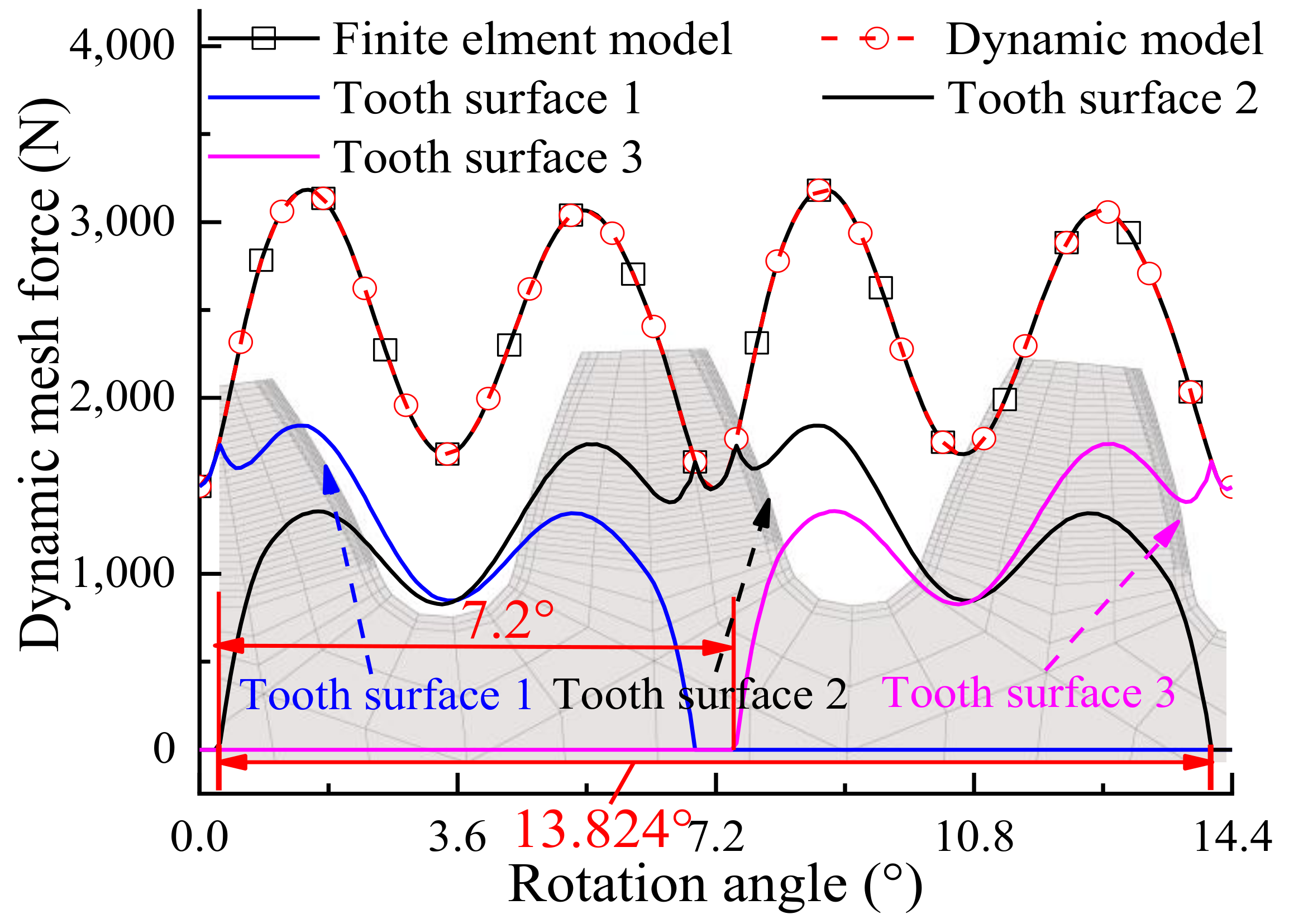
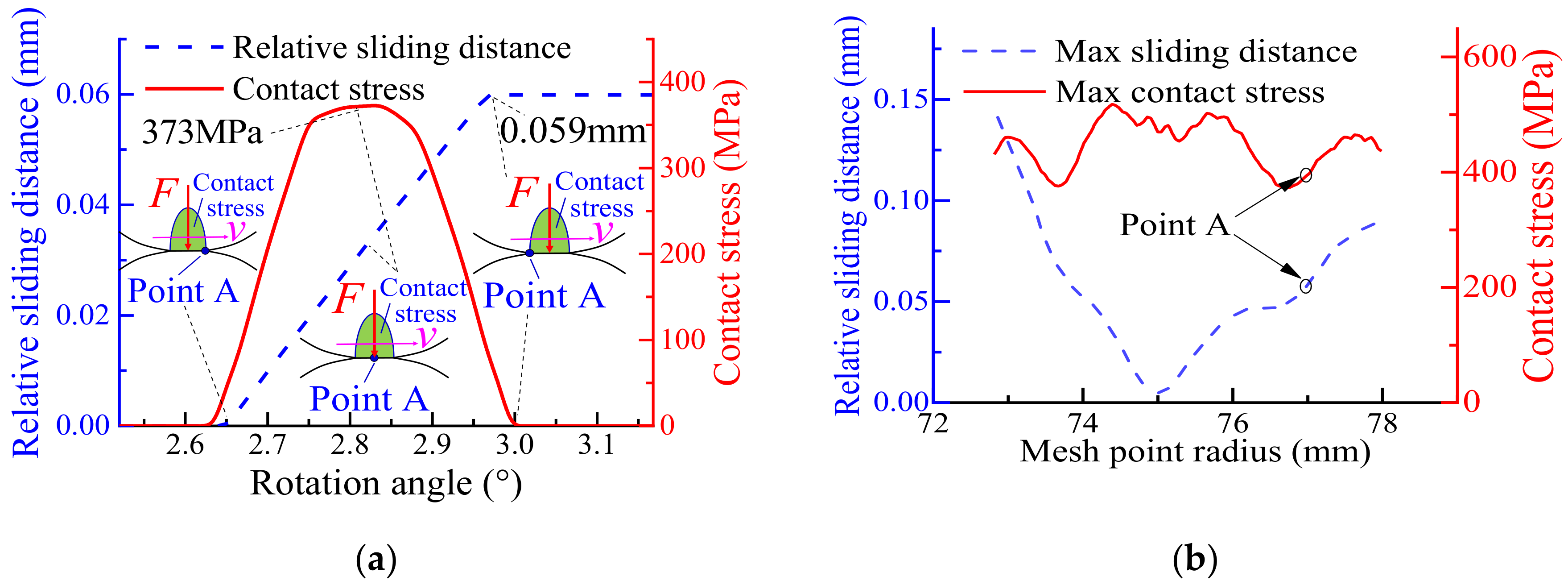
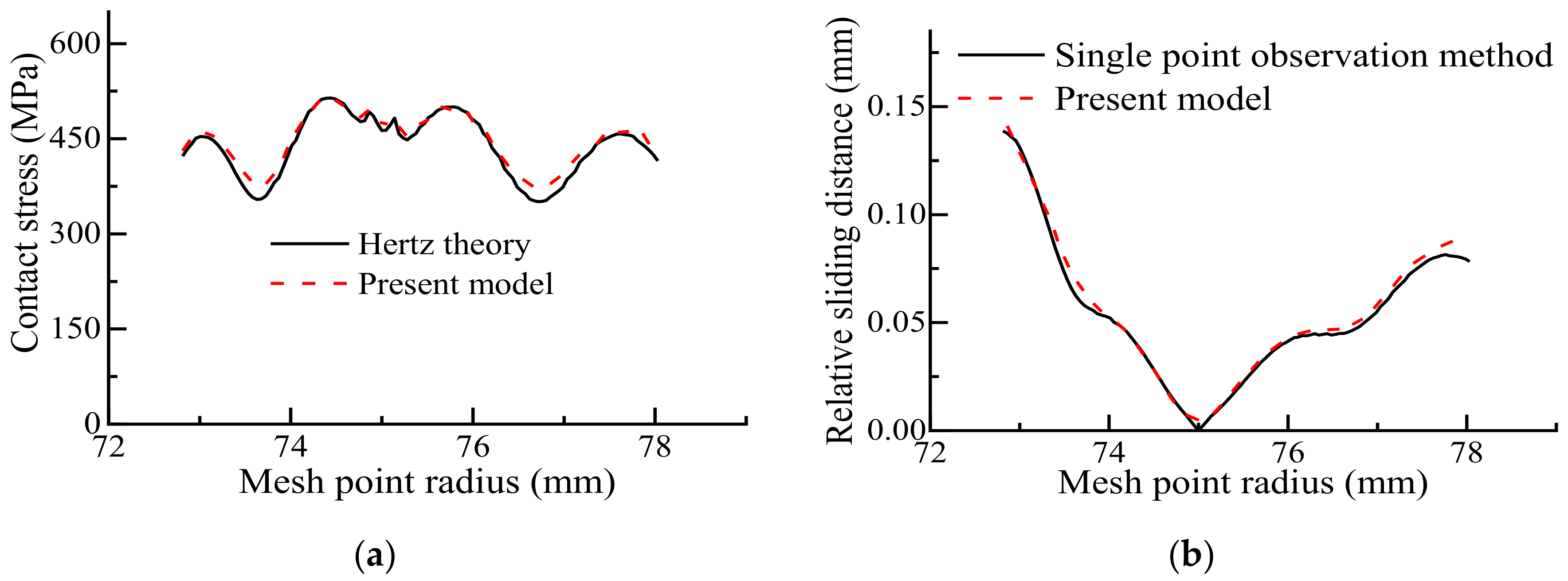
The comparison between the dynamic mesh force varying with the rotation angle as calculated by the FEM model and dynamic model is shown in Figure 16. Figure 17a shows the time-varying contact stress and relative sliding distance of mesh point A (the radius of this mesh point is 77 mm), and Figure 17b shows the max contact stress and relative sliding distance of each mesh point. Figure 18a shows the maximum contact stress of each mesh point on the tooth surface calculated based on the present model and Hertz theory. Figure 18b shows the maximum sliding distance of each mesh point on the tooth surface as calculated by the present model and the single point observation method.
Figure 16 shows that the dynamic mesh force calculated by the present model is completely consistent with the dynamic mesh force calculated by the dynamic model, indicating that the FEM model proposed in this paper is reasonable. The angle of a single tooth surface participating in the mesh is 13.824°, and the difference angle between two adjacent tooth surfaces entering the mesh is 7.2°. Therefore, the real contact ratio of the gear is 1.92, which is greater than the theoretical involute contact ratio (ICR) of 1.77. This difference is due to the deformation of the gear during operation, which increases the contact ratio [46].
As shown in Figure 17a, mesh point A starts to engage when the pinion rotates by 2.65° and exits engagement when the pinion rotates by 3.0°. At this time, the maximum sliding distance is 0.059 mm. However, the maximum contact stress of mesh point A occurs when the rotation angle of pinion is 2.81°. Figure 17b shows that the fluctuation trend of the tooth surface maximum contact stress is consistent with that of the dynamic mesh force on the tooth surface. The maximum relative sliding distance of the tooth surface appears at the tooth root, and the maximum relative sliding distance at the pitch point is the smallest.
Figure 18 shows that the maximum contact stress of each mesh point on the tooth surface calculated by the present model is consistent with the result calculated based on the Hertz contact theory. Additionally, the maximum relative sliding distance of each mesh point on the tooth surface calculated by the present model is consistent with the result calculated with the single point observation method, showing that the present model has high accuracy in calculating the maximum contact stress and relative sliding distance.
3.5. Wear Depth Calculation Results
3.5.1. Tooth Surface Wear Depths for Different Wear Times
According to the research results of Huali Ding and A. Kahraman [4], when the pinion and gear are the same, the wear curves of the two gears are similar. Therefore, this paper analyzes only the tooth surface wear of the pinions.
- wear depth in one mesh process;
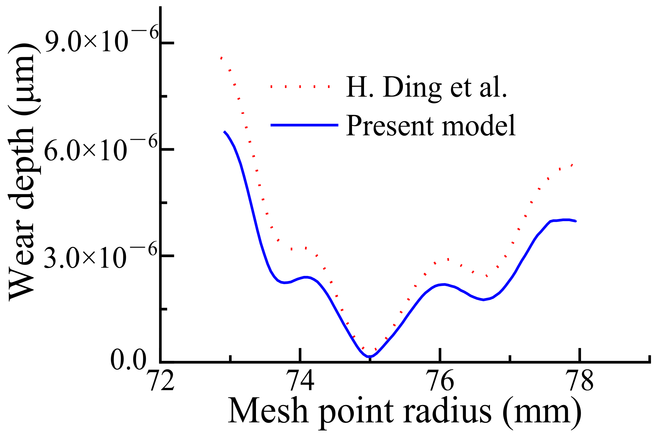
To study the effects of the time-varying contact stress and relative sliding distance on the calculation results of wear depth, Equations (21) and (22) are used to calculate the tooth surface wear depth in one mesh process. The calculation results for the wear depth, as calculated through the method proposed by H. Ding et al. [4,35,45] and the method proposed in this paper, are shown in Figure 19. As observed in Figure 19, the wear depth obtained through the calculation model proposed in this paper is smaller than that obtained by the calculation models proposed by H. Ding et al. [4,35,45], although this model is more in line with the theory.
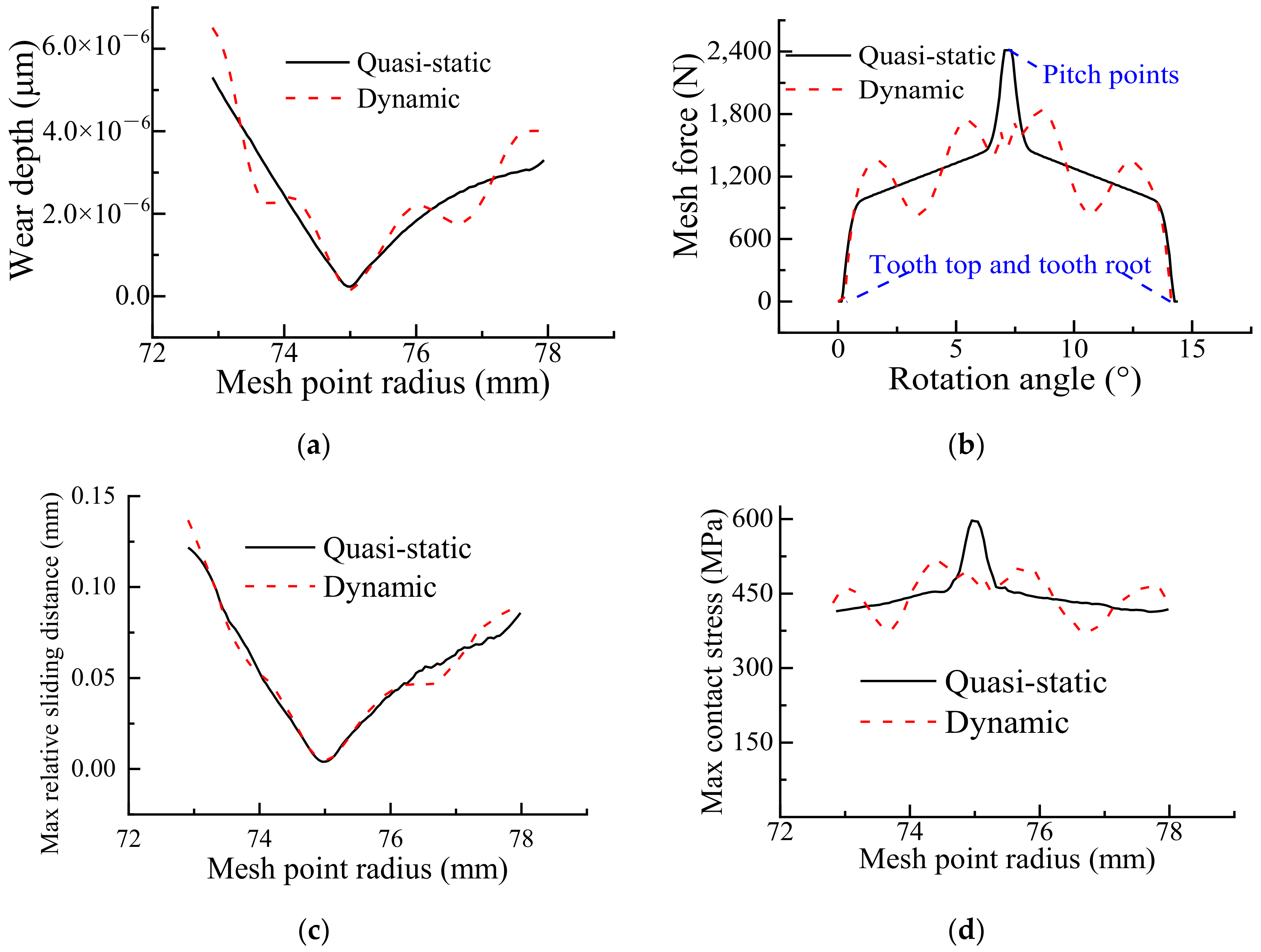
To study the influence of the dynamic mesh force on the tooth wear depth, this paper compares the wear depth calculation results based on the quasi-static contact analysis model (the dynamic torque of the FEM model shown in Figure 8 is replaced with a constant torque) and the contact analysis model considering the dynamic mesh force proposed in Section 2.2.4. The comparison results are shown in Figure 20a. As observed in Figure 20a, the wear depth curves calculated by the quasi-static contact model and the contact model considering the dynamic mesh force exhibit the smallest wear depth at the pitch point and the largest wear depth at the tooth root. The wear depth calculated by the quasi-static contact model increases monotonically from the pitch point to the top and root of the tooth. The wear depth calculated with the contact model considering the dynamic mesh force increases nonmonotonically from the pitch point to the top and root of the tooth.
This phenomenon occurs because the tooth surface mesh force of the quasi-static contact model, as shown in Figure 20b, increases monotonically from the tooth top to the pitch point and decreases monotonically from the pitch point to the tooth root. This relationship means that the maximum relative sliding distance from the tooth top to the pitch point decreases monotonically, and the maximum contact stress on the tooth surface increases monotonically. The maximum relative sliding distance from the pitch point to the tooth root decreases monotonically, as shown in Figure 20c, and the tooth surface maximum contact stress increases monotonically, as shown in Figure 20d. As shown in Figure 20b, for the contact model considering the dynamic mesh force, the tooth surface mesh force increases nonmonotonically from the tooth top to the pitch point and decreases nonmonotonically from the pitch point to the tooth root. This relationship means that the maximum relative sliding distance from the tooth top to the pitch point decreases nonmonotonically, and the maximum contact stress on the tooth surface increases nonmonotonically. The maximum relative sliding distance from the pitch point to the tooth root decreases nonmonotonically, as shown in Figure 20c, and the tooth surface maximum contact stress increases nonmonotonically, as shown in Figure 20d. In general, a large mesh force leads to a large wear depth, and a small mesh force leads to a smaller wear depth; this is because a large mesh force leads to a large contact width and large contact stress.
- wear depth with different wear times;
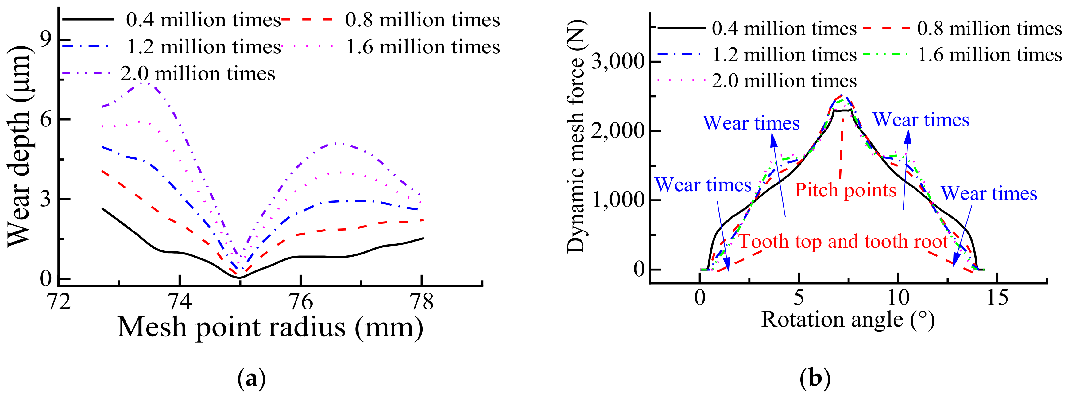
To study the wear depth of the tooth surface with different wear times, the wear depth is calculated at different times. Figure 21a shows the tooth surface wear depths for different wear times. As shown in Figure 21a, the wear depth increases with increasing wear time. The minimum wear depth on the tooth surface is always maintained at the pitch point, but the position of the maximum wear depth changes with increasing wear time. As the wear time continues to increase, the increase in the wear at the tooth top and root slows down gradually, causing the position of the maximum wear depth to gradually approach the pitch point. This occurs because when the wear number is small, the wear depths at the tooth top and tooth root increase rapidly with increasing wear time. This increase then leads to a gradual decrease in the mesh force when the tooth top engages with the tooth root, while the mesh force increases gradually when the mesh point between the tooth top and the pitch point is engaged. The curve of the tooth surface mesh force variation with the rotation angle for different wear times is shown in Figure 21b.
3.5.2. Wear Times Effect on the Dynamic Characteristics
- Wear depth calculation results
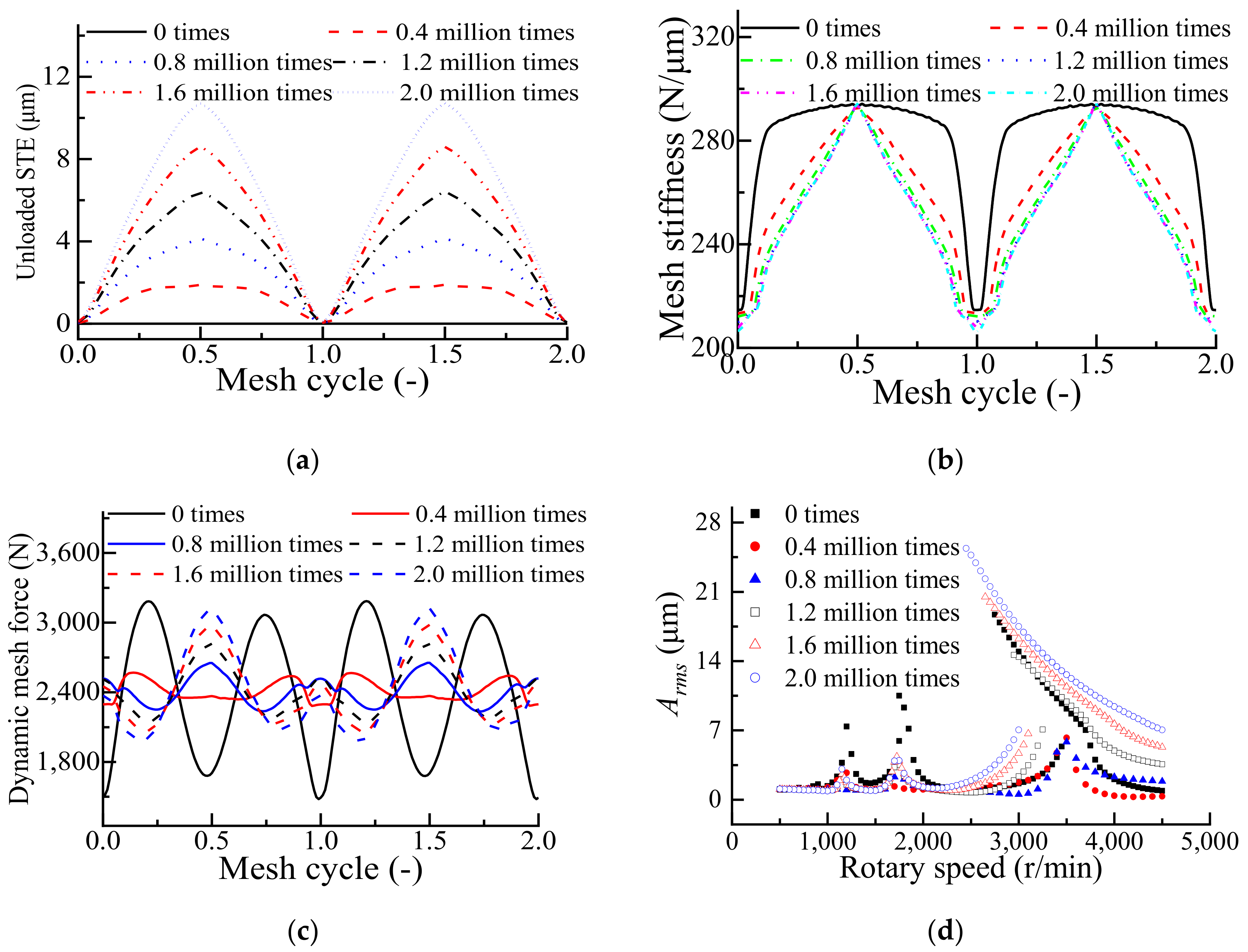
To study the influence of the tooth surface wear time on the gear dynamic characteristics, the unloaded STE, mesh stiffness, dynamic meshing force and equivalent root-mean-square amplitude of the DTE at different speeds and different wear times were obtained in the wear calculation process. Figure 22a shows the unloaded STE for different wear times, Figure 22b shows the mesh stiffness for different wear times, Figure 22c shows the dynamic mesh force of the tooth surface for different wear times, and Figure 22d shows the equivalent root-mean-square amplitude of the DTE at different speeds for different wear times.
As shown in Figure 22a, the unloaded STE increases with increasing wear time. The unloaded STE is smallest when the pitch points are engaged and largest when the middle position of the tooth top and pitch point is engaged with the middle position of the tooth root and pitch point. This occurs because the wear depth at the pitch point is smallest and the wear depths at the middle position of the tooth top and pitch point and the middle position of the tooth root and pitch point are large. This result is consistent with the results obtained in [13].
As shown in Figure 22b, the mesh stiffness decreases with increasing wear time. This occurs because the tooth thickness decreases with increasing wear time. This result is consistent with the results obtained in [12,16]. When the wear time is less than 0.8 million times, the change in the mesh stiffness is more obvious. This occurs because before the gear is worn, there is tooth interference at the changeover moment from the single-tooth to the double-tooth mesh. With the increase in wear time, the wear depth at the tooth top increases, which gradually eliminates the tooth interference at the changeover moment from the single-tooth to the double-tooth mesh. With increasing wear time, the mesh stiffness at which the pitch points are engaged decreases clearly. This decrease occurs because the wear depths at both sides of the pitch point are greater than that at the pitch point, reducing the tooth profile radius at the pitch point and leading to a greater Hertz contact deformation. In addition, the single tooth mesh area gradually increases because, with the increase in the wear depth at the tooth top area, the tooth top no longer participates in the mesh, and the ICR is gradually reduced.
As shown in Figure 22c, before the tooth surface is worn, there is a large fluctuation in the mesh force at the changeover moment between single- and double-tooth meshing; this is caused by the tooth interference at the changeover moment. When the wear time is less than 0.8 million times, the tooth interference is gradually eliminated with increasing wear time, and the fluctuation of the mesh force caused by interference is reduced. However, with increasing wear time, the wear depth of the tooth surface increases, causing a large unloaded STE and finally increasing the fluctuation of the tooth surface meshing force. Overall, when the wear time is less than 0.8 million times, the peak-to-peak mesh force decreases with the number of wear times; when the wear time is more than 0.8 million times, the peak-to-peak mesh force increases with the wear times.
As shown in Figure 22d, the resonance speed of the gear gradually decreases with increasing wear time. This occurs because the tooth thickness decreases with increasing wear depth, resulting in a gradual decrease in the mesh stiffness. In addition, when the wear time reaches 0.4 million times, the tooth separation phenomenon is eliminated. However, when the wear time reaches 0.8 million times, the tooth separation phenomenon appears again.
4. Conclusions
In this paper, a wear coefficient calculation method based on the pin-on-disc wear test is proposed. A wear depth calculation method that can be used to update the geometry of the wear contact surface is proposed based on the FEM. Additionally, a dynamic contact analysis method for the tooth surface is proposed based on the dynamic model and FEM. Finally, the tooth surface wear calculation method is defined.
- To verify the feasibility of the wear depth calculation method and the wear coefficient calculation method, the pin-on-disc wear test and simulation calculation are carried out on steel 20CrMoH as an example. The calculation results are consistent with the test results, indicating the feasibility of the wear depth calculation method and the wear coefficient calculation method.
- To verify the correctness of the dynamic model and dynamic contact analysis model, the pair of spur gears in [38] are taken as an example to calculate the equivalent root-mean-square amplitude of the DTE based on the dynamic model and compared with the experimental results to prove the accuracy of the dynamic model. The maximum contact stress and relative sliding distance are calculated by the dynamic contact analysis model and compared to the Hertz theory calculation results, proving the accuracy of the dynamic contact stress model of the tooth surface.
- To analyze the influence of the time-varying characteristics of the tooth contact stress and relative sliding distance on the tooth wear depth, maximum contact stress and maximum relative sliding distance calculation, the time-varying contact stress and time-varying sliding distance are used to calculate the tooth wear depth. The results show that the wear depth calculated without considering the time-varying characteristics is larger than that with the time-varying characteristics.
- To analyze the influence of the dynamic mesh force on the tooth surface wear depth, the tooth surface wear depth is calculated and compared by using the quasi-static contact model and dynamic contact model. The results show that there is a strong relationship between the tooth surface wear depth and dynamic mesh force.
- To study the wear depth at different wear times and the influence of different wear times on the dynamic characteristics of the gears, the wear depth, unloaded STE, mesh stiffness, dynamic mesh force and equivalent root-mean-square amplitude of the DTE under different speeds for different wear times are displayed. The results show that a small amount of wear may reduce the vibration of the gear, and excessive wear aggravates the vibration of the gear. These results also show that the wear depth increases with increasing wear time. When the wear time of the involute spur gear is shorter, the tooth interference may be reduced to reduce the gear vibration. When the wear time is too long, the unloaded STE caused by wear becomes larger, and the vibration of the gear becomes larger.
Author Contributions
Conceptualization, methodology, validation, data curation, formal analysis, investigation, writing—original draft, Z.H.; methodology, validation, data curation, X.Z.; validation, data curation, Y.Y.; supervision and writing—review and editing, Y.H. All authors have read and agreed to the published version of the manuscript.
Funding
The authors would like to acknowledge the foundation of the National Science and Technology Major Project (No: HT-J2019-IV-0001-0068).
Institutional Review Board Statement
This study did not require ethical approval.
Informed Consent Statement
Not applicable.
Data Availability Statement
Not applicable.
Conflicts of Interest
The authors declare that they have no conflict of interest.
References
- Wang, Y.; Wei, J.; Sun, W. Parameter Sensitivity Analysis of Gear Contact in Gear-Bearing-Rotor System Based on Romax. Appl. Mech. Mater. 2014, 472, 91–99. [Google Scholar] [CrossRef]
- Hsieh, L.-C.; Chen, T.-H. The engineering design and transmission efficiency verification of helical spur gear transmission with a single gear pair. Trans. Can. Soc. Mech. Eng. 2016, 40, 981–993. [Google Scholar] [CrossRef]
- Xu, X.; Liu, G.; Liang, X. Research on the Electromagnetic Conversion Method of Stator Current for Local Fault Detection of a Planetary Gearbox. Machines 2021, 9, 277. [Google Scholar] [CrossRef]
- Ding, H.; Kahraman, A. Interactions between nonlinear spur gear dynamics and surface wear. J. Sound Vib. 2007, 307, 662–679. [Google Scholar] [CrossRef]
- Liang, X.; Zuo, M.J.; Feng, Z. Dynamic modeling of gearbox faults: A review. Mech. Syst. Signal Processing 2018, 98, 852–876. [Google Scholar] [CrossRef]
- Sari, M.R.; Haiahem, A.; Flamand, L. Effect of lubricant contamination on gear wear. Tribol. Lett. 2007, 27, 119–126. [Google Scholar] [CrossRef]
- Brethee, K.F.; Zhen, D.; Gu, F.; Ball, A.D. Helical gear wear monitoring: Modelling and experimental validation. Mech. Mach. Theory 2017, 117, 210–229. [Google Scholar] [CrossRef]
- Feng, K.; Smith, W.A.; Peng, Z. Use of an improved vibration-based updating methodology for gear wear prediction. Eng. Fail. Anal. 2021, 120, 105066. [Google Scholar] [CrossRef]
- Flodin, A.; Andersson, S. Simulation of mild wear in spur gears. Wear 1997, 207, 16–23. [Google Scholar] [CrossRef]
- Flodin, A.; Andersson, S. Simulation of mild wear in helical gears. Wear 2000, 241, 123–128. [Google Scholar] [CrossRef]
- Flodin, A.; Andersson, S. A simplified model for wear prediction in helical gears. Wear 2001, 249, 285–292. [Google Scholar] [CrossRef]
- Huangfu, Y.; Chen, K.; Ma, H.; Li, X.; Yu, X.; Zhao, B.; Wen, B. Investigation on meshing and dynamic characteristics of spur gears with tip relief under wear fault. Sci. China Technol. Sci. 2019, 62, 1948–1960. [Google Scholar] [CrossRef]
- Shen, Z.; Qiao, B.; Yang, L.; Luo, W.; Yang, Z.; Chen, X. Fault mechanism and dynamic modeling of planetary gear with gear wear. Mech. Mach. Theory 2021, 155, 104098. [Google Scholar] [CrossRef]
- Wang, H.; Zhou, C.; Wang, H.; Hu, B.; Liu, Z. A novel contact model for rough surfaces using piecewise linear interpolation and its application in gear wear. Wear 2021, 476, 203685. [Google Scholar] [CrossRef]
- Archard, J. Contact and rubbing of flat surfaces. J. Appl. Phys. 1953, 24, 981–988. [Google Scholar] [CrossRef]
- Park, D.; Kolivand, M.; Kahraman, A. Prediction of surface wear of hypoid gears using a semi-analytical contact model. Mech. Mach. Theory 2012, 52, 180–194. [Google Scholar] [CrossRef]
- Tunalioğlu, M.Ş.; Tuc, B. Theoretical and experimental investigation of wear in internal gears. Wear 2014, 309, 208–215. [Google Scholar] [CrossRef]
- Bajpai, P.; Kahraman, A.; Anderson, N. A surface wear prediction model for parallel-axis gear pairs. In Proceedings of the International Design Engineering Technical Conferences and Computers and Information in Engineering Conference, Chicago, IL, USA, 2–6 September 2003; pp. 817–826. [Google Scholar]
- Hegadekatte, V.; Huber, N.; Kraft, O. Finite element based simulation of dry sliding wear. Model. Simul. Mater. Sci. Eng. 2004, 13, 57. [Google Scholar] [CrossRef]
- Park, D.; Kahraman, A. A surface wear model for hypoid gear pairs. Wear 2009, 267, 1595–1604. [Google Scholar] [CrossRef]
- Hegadekatte, V.; Hilgert, J.; Kraft, O.; Huber, N. Multi time scale simulations for wear prediction in micro-gears. Wear 2010, 268, 316–324. [Google Scholar] [CrossRef] [Green Version]
- Zhang, J.; Liu, X. Effects of misalignment on surface wear of spur gears. Proc. Inst. Mech. Eng. Part J J. Eng. Tribol. 2015, 229, 1145–1158. [Google Scholar] [CrossRef]
- Hertz, H. On the contact of elastic solids. J. Reine Angew. Math. 1881, 92, 156–171. [Google Scholar] [CrossRef]
- Andersson, S. Partial EHD Theory and Initial Wear of Gears; Royal Institute of Technology: Stockholm, Sweden, 1975. [Google Scholar]
- Lundvall, O.; Klarbring, A. Simulation of wear by use of a nonsmooth Newton method—A spur gear application. Mech. Struct. Mach. 2001, 29, 223–238. [Google Scholar] [CrossRef]
- Shen, Z.; Qiao, B.; Yang, L.; Luo, W.; Chen, X. Evaluating the influence of tooth surface wear on TVMS of planetary gear set. Mech. Mach. Theory 2019, 136, 206–223. [Google Scholar] [CrossRef]
- Karpat, F.; Ekwaro-Osire, S. Influence of tip relief modification on the wear of spur gears with asymmetric teeth. Tribol. Trans. 2008, 51, 581–588. [Google Scholar] [CrossRef]
- Park, D.; Kolivand, M.; Kahraman, A. An approximate method to predict surface wear of hypoid gears using surface interpolation. Mech. Mach. Theory 2014, 71, 64–78. [Google Scholar] [CrossRef]
- Huang, D.; Wang, Z.; Kubo, A. Hypoid gear integrated wear model and experimental verification design and test. Int. J. Mech. Sci. 2020, 166, 105228. [Google Scholar] [CrossRef]
- Zhou, C.; Wang, H. An adhesive wear prediction method for double helical gears based on enhanced coordinate transformation and generalized sliding distance model. Mech. Mach. Theory 2018, 128, 58–83. [Google Scholar] [CrossRef]
- Chen, Z.; Shao, Y. Mesh stiffness calculation of a spur gear pair with tooth profile modification and tooth root crack. Mech. Mach. Theory 2013, 62, 63–74. [Google Scholar] [CrossRef]
- Eymard, R.; Gallouët, T. H-convergence and numerical schemes for elliptic problems. SIAM J. Numer. Anal. 2003, 41, 539–562. [Google Scholar] [CrossRef] [Green Version]
- Mudunuru, M.K.; Nakshatrala, K. On enforcing maximum principles and achieving element-wise species balance for advection–diffusion–reaction equations under the finite element method. J. Comput. Phys. 2016, 305, 448–493. [Google Scholar] [CrossRef] [Green Version]
- Lin, A.-D.; Kuang, J.-H. Dynamic interaction between contact loads and tooth wear of engaged plastic gear pairs. Int. J. Mech. Sci. 2008, 50, 205–213. [Google Scholar] [CrossRef]
- Osman, T.; Velex, P. Static and dynamic simulations of mild abrasive wear in wide-faced solid spur and helical gears. Mech. Mach. Theory 2010, 45, 911–924. [Google Scholar] [CrossRef]
- Liu, X.; Yang, Y.; Zhang, J. Investigation on coupling effects between surface wear and dynamics in a spur gear system. Tribol. Int. 2016, 101, 383–394. [Google Scholar] [CrossRef]
- Huangfu, Y.; Zhao, Z.; Ma, H.; Han, H.; Chen, K. Effects of tooth modifications on the dynamic characteristics of thin-rimmed gears under surface wear. Mech. Mach. Theory 2020, 150, 103870. [Google Scholar] [CrossRef]
- Kahraman, A.; Blankenship, G. Effect of involute contact ratio on spur gear dynamics. J. Mech. Des. 1999, 1, 112–118. [Google Scholar] [CrossRef]
- Kahraman, A.; Singh, R. Non-linear dynamics of a spur gear pair. J. Sound Vib. 1990, 142, 49–75. [Google Scholar] [CrossRef]
- Zheng, X.; Luo, W.; Hu, Y.; He, Z.; Wang, S. Study on the Mesh Stiffness and Nonlinear Dynamics Accounting for Centrifugal Effect of High-speed Spur Gears. Mech. Mach. Theory 2022, 170, 104686. [Google Scholar] [CrossRef]
- Cooley, C.G.; Liu, C.; Dai, X.; Parker, R.G. Gear tooth mesh stiffness: A comparison of calculation approaches. Mech. Mach. Theory 2016, 105, 540–553. [Google Scholar] [CrossRef] [Green Version]
- Howard, I.; Jia, S.; Wang, J. The dynamic modelling of a spur gear in mesh including friction and a crack. Mech. Syst. Signal Processing 2001, 15, 831–853. [Google Scholar] [CrossRef]
- Tamminana, V.K.; Kahraman, A.; Vijayakar, S. A study of the relationship between the dynamic factors and the dynamic transmission error of spur gear pairs. J. Mech. Des. 2007, 129, 75–84. [Google Scholar] [CrossRef]
- Eritenel, T.; Parker, R.G. An investigation of tooth mesh nonlinearity and partial contact loss in gear pairs using a lumped-parameter model. Mech. Mach. Theory 2012, 56, 28–51. [Google Scholar] [CrossRef]
- Kahraman, A.; Bajpai, P.; Anderson, N.E. Influence of Tooth Profile Deviations on Helical Gear Wear. J. Mech. Des. 2005, 127, 1311. [Google Scholar] [CrossRef]
- Tang, J.-Y.; Liu, Y.-P. Loaded multi-tooth contact analysis and calculation for contact stress of face-gear drive with spur involute pinion. J. Cent. South Univ. 2013, 20, 354–362. [Google Scholar] [CrossRef]
Figure 1.
Pin-On-Disc wear test principle and test sample diagram.

Figure 2.
Wear calculation process based on the FEM.

Figure 3.
FEM model for pin-on-disc wear test.

Figure 4.
Dynamic model of a spur gear pair.

Figure 5.
Gear mesh state for (a) DTE greater than 0, (b) DTE greater than and less than 0, and (c) DTE less than .
Figure 5.
Gear mesh state for (a) DTE greater than 0, (b) DTE greater than and less than 0, and (c) DTE less than .

Figure 6.
(a) Unloaded STE caused by wear and (b) FEM model for calculating the unloaded STE.

Figure 7.
FEM model for the gear mesh stiffness calculation.

Figure 8.
Nonlinear contact analysis model considering the dynamic mesh force.

Figure 9.
(a) Tooth contact simplification and (b) Hertz contact model.

Figure 10.
(a) Position of mesh point K and (b) meshing process for mesh point K.

Figure 11.
The calculation flow for the tooth surface wear.

Figure 12.
Pin-on-disc wear test principle and test sample diagram.

Figure 13.
Comparison between the simulation and test results.

Figure 14.
(a) Mesh stiffness calculation results, (b) DTE at 2000 r/min, (c) harmonic amplitude of the DTE when the speed is 2000 r/min, and (d) equivalent root-mean-square amplitude of the DTE with different speeds.
Figure 14.
(a) Mesh stiffness calculation results, (b) DTE at 2000 r/min, (c) harmonic amplitude of the DTE when the speed is 2000 r/min, and (d) equivalent root-mean-square amplitude of the DTE with different speeds.

Figure 15.
(a) Dynamic mesh force at 2000 r/min, and (b) dynamic torque.

Figure 16.
The comparison between the dynamic mesh force obtained by dynamic model and dynamic contact analysis model.
Figure 16.
The comparison between the dynamic mesh force obtained by dynamic model and dynamic contact analysis model.

Figure 17.
(a) Varying contact stress and relative sliding distance with the rotation angle of mesh point A and (b) the max contact stress and relative sliding distance of each mesh point.
Figure 17.
(a) Varying contact stress and relative sliding distance with the rotation angle of mesh point A and (b) the max contact stress and relative sliding distance of each mesh point.

Figure 18.
(a) Maximum contact stress and (b) maximum relative sliding distance of each mesh point.

Figure 19.
Varying dynamic mesh force with the rotation angle.

Figure 20.
Comparisons of the calculation results between the quasi-static contact model and contact model considering dynamic mesh force for the (a) wear depth, (b) tooth surface mesh force, (c) max relative sliding distance, and (d) max contact stress.
Figure 20.
Comparisons of the calculation results between the quasi-static contact model and contact model considering dynamic mesh force for the (a) wear depth, (b) tooth surface mesh force, (c) max relative sliding distance, and (d) max contact stress.

Figure 21.
(a) Tooth surface wear depths and (b) tooth surface mesh forces for different wear times.
Figure 21.
(a) Tooth surface wear depths and (b) tooth surface mesh forces for different wear times.

Figure 22.
(a) Unloaded STE, (b) mesh stiffness, (c) dynamic mesh force, and (d) equivalent root-mean-square amplitude of the DTE for different wear times.
Figure 22.
(a) Unloaded STE, (b) mesh stiffness, (c) dynamic mesh force, and (d) equivalent root-mean-square amplitude of the DTE for different wear times.


Table 1.
The chemical composition of 20CrMoH material (wt, %).
| 20CrMoH | C | Si | Mn | Cr | Mo | P | S |
|---|---|---|---|---|---|---|---|
| Wt (%) | 0.17–0.23 | 0.17–0.37 | 0.55–0.90 | 0.85–1.25 | 0.15–0.35 | ≤0.03 | ≤0.03 |
Table 2.
Gear parameters.
| Parameters | Pinion | Gear | Parameters | Pinion | Gear |
|---|---|---|---|---|---|
| Number of teeth | 50 | 50 | Density (kg/m3) | 7850 | 7850 |
| Tooth width (mm) | 20 | 20 | Center distance (mm) | 150 | |
| Young’s modulus (GPa) | 210 | 210 | Backlash (μm) | 50 | |
| Pressure angle (°) | 20 | 20 | Involute contact ratio (ICR) | 1.77 | |
| Poisson’s ratio | 0.3 | 0.3 | Center distance (mm) | 150 | |
| Rotary inertia (kg·mm2) | 7.65 | 7.65 | - | - | |
Publisher’s Note: MDPI stays neutral with regard to jurisdictional claims in published maps and institutional affiliations. |
© 2022 by the authors. Licensee MDPI, Basel, Switzerland. This article is an open access article distributed under the terms and conditions of the Creative Commons Attribution (CC BY) license (https://creativecommons.org/licenses/by/4.0/).
Share and Cite
MDPI and ACS Style
He, Z.; Hu, Y.; Zheng, X.; Yu, Y. A Calculation Method for Tooth Wear Depth Based on the Finite Element Method That Considers the Dynamic Mesh Force. Machines 2022, 10, 69. https://0-doi-org.brum.beds.ac.uk/10.3390/machines10020069
AMA Style
He Z, Hu Y, Zheng X, Yu Y. A Calculation Method for Tooth Wear Depth Based on the Finite Element Method That Considers the Dynamic Mesh Force. Machines. 2022; 10(2):69. https://0-doi-org.brum.beds.ac.uk/10.3390/machines10020069
Chicago/Turabian StyleHe, Zao, Yumei Hu, Xingyuan Zheng, and Yuanyuan Yu. 2022. "A Calculation Method for Tooth Wear Depth Based on the Finite Element Method That Considers the Dynamic Mesh Force" Machines 10, no. 2: 69. https://0-doi-org.brum.beds.ac.uk/10.3390/machines10020069
Note that from the first issue of 2016, this journal uses article numbers instead of page numbers. See further details here.