

An Integrated Architecture for Robotic Assembly and Inspection of a Composite Fuselage Panel with an Industry 5.0 Perspective

Dipartimento di Ingegneria, Università degli Studi della Campania Luigi Vanvitelli, 81031 Aversa, Italy
*
Author to whom correspondence should be addressed.
Machines 2024, 12(2), 103; https://0-doi-org.brum.beds.ac.uk/10.3390/machines12020103
Submission received: 26 November 2023
/
Revised: 18 January 2024
/
Accepted: 22 January 2024
/
Published: 1 February 2024
(This article belongs to the Special Issue AI-Integrated Advanced Robotics towards Industry 5.0)
Abstract
:Aeronautical robotic applications use quite large, heavy robots with huge end effectors that are frequently multifunctional. An assembly jig to hold a fuselage panel and two medium-sized six-axis robots fixed on linear axes, referred to as the internal and the external robot with respect to the curvature of the panel, make up the Lean robotized AssemBly and cOntrol of composite aeRostructures (LABOR) work cell. A distributed software architecture is proposed in which individual modules are developed to execute specific subprocesses, each implementing innovative algorithms that solve the main drawbacks of state-of-the-art solutions. Real-time referencing adopts a point-cloud-based strategy to reconstruct and process the part before drilling, avoiding hole positioning errors. Accurate concentric countersink diameters are made possible through the automatic adjustment of the drilling tool with respect to the skin panel, which guarantees its orthogonality, as well as the implementation of process parameter optimization algorithms based on historical results that compensate for the wear of the drilling bits. Automatic sealing and fastening strategies that involve the measurement of the main fastener quality parameters allow for the complete verification of the entire assembly process of each part. Additionally, an advanced multimodal perception system continuously monitors the collaborative workspace to ensure safe human–robot collaboration (HRC) tasks. Through this integrated architecture, LABOR substantially reduces expenses and facilitates maintenance and programming.
1. Introduction
The assembly and inspection processes of fuselage panels in aerospace manufacturing are increasingly performed automatically using robotized solutions, with the goal of replacing traditional manual methods. The main challenge of the LABOR work cell [1] is the creation of a lean and flexible automated system that improves quality standards and production rates, as well as efficiency. The assembly process is composed of a succession of very complex subprocesses, i.e., referencing, drilling, sealing, fastening, and inspection, which individually require a high level of performance to obtain a result that meets strict aeronautical requirements. The assembly process can also require human intervention, such as during the dismantling and consequent deburring of the metal parts. To avoid interrupting the automatic process of the system and, therefore, stopping the robots, thereby lengthening production times, the LABOR architecture was developed not only to execute high-performance algorithms to solve the individual subprocesses but also to include HRC strategies to allow humans to carry out these operations while robots continue their work cycles. Compliant with the Industry 5.0 perspective [2], the main distinguishing feature of the LABOR human–robot collaboration module is that the machine works together with a human worker, as no safety barrier is employed between the robot and the human worker and they share the same workspace, even though they perform different tasks, while guaranteeing operator safety.
1.1. Related Works
The Global Market Forecast [3] states that the years 2023–2042 will be associated with a forward-looking perspective on fleet evolution and air traffic. In order to lower manufacturing costs and increase efficiency rates, the aviation sector urgently needs to increase productivity. The use of robotics or automated systems is extremely rare, particularly for regional aircraft manufacturing lines, where the necessary level of positioning accuracy can only be ensured by employing expensive external metrology devices. Currently available fuselage assembly solutions include the Airbus A320 [4], the Bombardier CSeries Aircraft [5], and FAUB [6]. These solutions rely on large robots, heavy end effectors, and expensive measurement systems to compensate for their limited absolute accuracy and inevitable calibration errors, resulting in a very slow and poorly performing process, as well as making it impossible to realize HRC activities. On the contrary, a mobile manipulator with tactile sensors was proposed as part of the VALERI project [7] in 2017 to assist human operators. Unfortunately, collaborative robots and physical-contact detection systems represent risky solutions associated with needless production time waste and low efficiency; hence, they are not appropriate for usage in industrial settings. Regarding smart tools, one of the most versatile end effectors for composite aerostructure assemblies is the MFEE from Kuka Systems Aerospace. It has LABOR-compliant functionalities, but, because of its size and weight, it needs a robot payload greater than 210 kg and can only achieve ±0.5 mm positioning accuracy. As discussed in [8], the LABOR work cell falls into the hybrid assembly category, which combines manual and automated assemblies. A study of an HRC framework for the execution of collaborative tasks in hybrid assembly cells was reported in [9]; a decision-making method allows for human–robot task allocation and the planning of sequential tasks assigned to a robot and a human in separate workspaces by using human body gestures to command and guide robots. Unfortunately, in a real assembly setting, task execution based on gesture recognition can be highly dangerous because it can mistakenly recognize a gesture from any operator crossing the shop floor; therefore, the strategy was developed without taking into consideration safety aspects according to the related safety norms. Furthermore, a collaborative scenario with separate workspaces and sequential tasks does not optimize the overall production times of an assembly cell. On the other hand, given the fundamental importance of task assignment in HRC scenarios, a human-centered collaborative assembly process should be developed, where the human reasonably decides which tasks should be automated, executing those that require high levels of competence, with the objective of increasing productivity [10]. In the literature, increasing efficiency and productivity at a reasonable cost remains an open research topic [11]. The research reported in [12] moved in this direction, presenting an HRC task in an assembly scenario in which the ABB YuMi collaborative robot interacts with a human operator to assemble a product box. This research underlines that the practical use of cobots is still far from implementation in a real assembly plant; the authors propose the implementation of advanced artificial vision applications for workspace context awareness and to guarantee the quality of the product and the safety of the operators.
1.2. The LABOR Work Cell Solution
The LABOR work cell was previously presented in [13], in which the design was deeply analyzed from the point of view of the adopted hardware solutions. LABOR adopts medium-sized robots to perform both the assembly and the inspection processes in a lean system and does not require an expensive external metrology system for accurate hole positioning, thanks to the developed smart inspection tools. In contrast, the authors extended the existing mechanical description by adding a description of the system software architecture shown in Figure 1. The main concept of the LABOR architecture is the development and integration of different intelligent modules. Each module is independent of the other modules, manages some hardware components of the work cell, and communicates only with the cell supervisor, i.e., the HMI module. An OPC-UA bus is used to send and receive commands and feedback between the modules. This communication protocol was adopted for its inherent flexibility, adaptability, and transparency, all of which are necessary to meet the requirements of the distributed intelligence strategy.
Note that this paper describes the innovative algorithms implemented to fulfil the strict technical requirements (Section 1.4) of each subprocess. The referencing module (Section 2) uses a strategy based on the point cloud to reconstruct and process the part. The module executes specific object or shape recognition strategies to process four different part typologies. The drilling module (Section 3) uses three laser distance sensors to align the drilling nose orthogonal to the skin panel and executes the drilling step based on real-time force/torque sensor feedback. Two optimization strategies have been implemented to avoid potential drilling errors and component wear. The sealing and fastening modules (Section 4) control a stepper motor that compresses the sealing cartridge according to the fastener to be installed. The system sets the correct fastening parameters by reading the specifications of the hole to be filled and independently processes seven different sizes of fasteners. The inspection module implements shape-from-shading techniques to measure the hole and countersink diameter (Section 3.3) and also point-cloud-based strategies for the quality check of the installed fastener (Section 4.1). The HRC module (Section 5) proposes a novel convolutional neural network (CNN) that improves the robustness of human tracking by fusing depth and thermal data using sensor fusion techniques, and it executes a robot speed control algorithm that implements a Speed and Separation Monitoring (SSM) scenario based on real-time risk assessment by fuzzy control logic.
Finally, to demonstrate how the work cell globally overcomes the drawbacks of the existing solutions, the paper presents experimental data (Section 6) collected by performing a complete assembly cycle on some aeronautical structural elements of a full-scale demonstrator. The aim of the presented results is to highlight the performance of the individual assembly subprocesses in order to demonstrate the benefits of the implemented software strategies. The demonstrator on which the LABOR assembly cell was tested consisted of a section of aircraft fuselage, shown in Figure 2 (left), made up of three sections labeled side (purple), keel (green), and crown (blue). Each section was divided into AFT (right) and FWD (left). The panels were assembled using a three-step process (or job). LABOR performs the first job, in which the complex thermoplastic composite parts described in Section 1.4 are assembled on the carbon-fiber-reinforced polymer (CFRP) skin panel. In this work, the FWD side panel shown in Figure 2 (right) is analyzed in detail and the results of its assembly are provided.
1.3. Summary of the Contributions
The overall contribution of the project to the state of the art is to increase the level of automation of the current assembly process of fuselage parts such as the panels and frames of a regional aircraft by using lean and flexible automated solutions, instead of fully manual assembly or complex ad hoc machine designs, as well as high-payload robots in conjunction with external measurement systems. The introduction of such a solution will also allow human operators to share the area with robots during the manufacturing process.
The most important contributions of the research work, which are summarized below, enable the realization of a fully functional, replicable, and therefore widely usable solution.
- the development of a distributed intelligence architecture that integrates different and independent intelligent modules to create a more flexible solution;
- the use of small to medium-sized industrial robots to carry out both assembly and inspection in a lean system;
- the development of a self-adapting system capable of performing the optimized automatic drilling and insertion of fasteners based on the integration of sensors and robotized systems for composite structures;
- the development of smart inspection tools that avoid the use of external, expensive measuring systems for the precise positioning of the hole and the quality control of both the main drilling and fastener parameters’ measurement;
- the development of a novel multimodal perception system for a workspace monitoring algorithm based on both sensor fusion to combine depth data with thermographic data and AI to robustly recognize human workers, with the aim of increasing work cell productivity by reducing false-positive detections;
- the development of a real-time risk assessment by a fuzzy control logic under human-in-the-loop analysis to control the robot speed in order to realize an efficient SSM scenario.
1.4. Technical Specifications
For reasons of confidentiality, some quantitative details about the technologies used for the assembly of the FWD side panel in the initial state of the LABOR cell cannot be disclosed. In principle, the panel is delivered with some parts fixed with temporary fasteners and other parts glued to the skin. The LABOR assembly cycle consists of the following steps: referencing the part to be assembled, drilling the holes, inspection of the drilled holes, sealing the fastener, installing the fastener, and inspection of the installed fastener. The cycle was performed for each part identified in Figure 2 (right), with the exception of the stringer door, the stringer joint, and the shear-ties connected to these stringers. These parts are only drilled and countersunk by the LABOR cell in the first phase (with the exception of the stringer joint, which is not drilled) and then manually removed to carry out further manual work outside the LABOR cell. These parts are then reassembled on the outer skin and the LABOR cell completes the sealing and riveting work. To improve productivity by reducing dead times, some of these disassembly and reassembly operations are performed by a human operator in the HRC work mode, while other operations are performed by the robots. Table 1 summarizes the number of parts to be assembled on the panel.
The target cycle time for the LABOR robotized cell is not specified for reasons of confidentiality, but it amounts to a time saving of around 47% compared to manual operation. Table 2 and Figure 3 indicate the most important features and requirements for drilling and fastening elements that the LABOR cell must fulfill.
1.5. The LABOR Work Cycle
The LABOR work cycle begins with the part program, which the user configures via the human-machine interface (HMI). The user selects the panel mounted on the jig and chooses the parts to be assembled by the machine. More specifically, the user defines the specific holes on the selected parts and the operations to be performed on each of these parts. In this way, the part program is fully customized. When the program is started, the machine automatically defines the optimized sequence of operations to be performed based on the nominal positions of the set parts that it must manage in order to minimize the process time (optimization of the number of jig rotations and the movements of the linear axes). The general program starts with the movement of the jig and the linear axes; it then moves the internal robot with the vision system to a rough position and then estimates the part pose through special recognition algorithms (Section 2.2). After this, the internal robot transmits the current position of the part to the external robot, which grabs the drilling tool and moves to the hole to be created, while the internal robot rotates the last joint to use the countersink tool (Section 3.1). Then, the external robot performs “one-shot drilling” while the internal robot performs the countersinking operation (Section 3.2). Then, the external robot changes its end effector: it leaves the drilling tool and keeps the fastening tool. Thus, it captures the correct fastener to be installed and applies the sealant to it to complete the automatic installation of the fastener on the panel (Section 4).
Note that the system allows co-working activities and that, during robotic operations, a human operator can enter the work cell to insert and remove temporary connectors, apply a sealant by interposition, or remove metal burrs from the edges of the holes. The HRC module (Section 5) ensures operator safety by modulating the robot speed in accordance with ISO 10218-1/2 [14,15] and ISO/TS 15066 [16]. In order to fully utilize the functionality of the HRC module, the work cycle of the side FWD panel, which requires manual assembly activities, has been redefined in terms of a fully manual work cycle (Table 3).
The main idea is that the human worker and the internal robot can work simultaneously on different panel areas, as shown in Figure 4. Simulated analyses estimate that LABOR reduces the working time by about 40% with respect to a fully manual process using a standard fully automated working cycle, while the percentage rises to 48% when using the HRC module.
The remaining section presents the details of each module by following the working cycle phases.
2. The Referencing Module
As shown in Figure 2, in aircraft assembly, each fuselage panel is composed of numerous parts according to the design criteria and technical requirements. The non-nominal shape of the parts and their non-nominal location on the skin can lead to dangerous fuselage panel deformation, as described in [17], which can be caused by using the traditional part-to-part (P2P) assembly strategy. P2P consists of joining two parts that have at least two coordination holes (CH). One part also has all the holes, called pilot holes (PH), which are then re-drilled into the second part after the two parts have been indexed using the CH. The CH and PH phases take a non-negligible amount of time, which depends on the size of the part and can even take months.
To save this time, the LABOR work cycle starts with a pre-assembled panel on which the parts have been manually glued or fastened on the skin by temporary fasteners. Thus, the system performs a 3D reconstruction of the local reference frame of the part with respect to the panel itself (referencing step) before starting the automatic assembly process and drills the holes in the correct positions. In aircraft manufacturing, the state of the art for the inspection of holes and fasteners also relies on a dedicated mechanical instrument for each measurement. In contrast, according to the LABOR approach to inspection described in [18], the internal robot is equipped with a Smart Inspection Tool (SIT) designed for two main objectives:
- executing the referencing process of the part (see Section 2.2);
- checking the diameters of the drilled hole and countersink (see Section 3.3) and the quality of the installed fasteners (see Section 4.1).
2.1. The Smart Inspection Tool
The most commonly used solutions for the automatic process inspection of drilled holes are non-contact image processing techniques based on the use of 2D cameras and lighting systems, such as in [19,20]. However, these solutions still have limitations, as they do not guarantee the desired accuracy specified in Table 2. The same limits were also found for standard solutions. For example, ref. [21] has tried to overcome these limitations by developing a machine vision system for online surface measurements for aerospace applications, but its product range is limited to the measurement of dents and flushness measurement. For a complete measurement set, ref. [22] introduced an instrument to measure the hole diameter, countersink diameter, countersink depth, grip length, and perpendicular measurement, but this device is designed for handheld use and cannot perform referencing tasks.
For these reasons, the SIT was integrated as an internal robotic end effector following the study conducted in [23], in which a profilometer consisting of a structured LED light pattern projector was combined with two cameras with a 35 mm lens to avoid undercutting. More specifically, the structured LED light projects a m wide line on the target surface and the use of a blue LED source (instead of a conventional laser) reduces speckles and increases the accuracy. The tool is mounted on an electric linear axis that moves the system in a perpendicular direction with respect to the projected line. A 3D point cloud merging strategy combines the two acquisitions to complete the reconstruction of the target surface. The developed merging strategy is based on the point cloud registration. More precisely, the transformation of a point cloud into the corresponding reference system of the target point cloud was performed. Then, the two point clouds were aligned by the Iterative Closest Point (ICP) [24] algorithm and, finally, the resulting points were merged into a single point cloud, which was then processed to extract the required measurement data. Note that the SIT was calibrated according to the procedure proposed in [25] so that its position with respect to the robot flange was known.
2.2. Part Referencing
From the software’s point of view, the SIT performs a scan of a suitable section of the part to obtain a 3D point cloud that can be processed. Depending on the type of part (shear-tie, stringer, frame, or window frame), the software executes a specific referencing algorithm to calculate the current local reference system of the part, , with respect to the internal robot vision system reference frame, , as shown in Figure 5 on the right, represented by the homogeneous transformation matrix .
The automatic process is based on the following assumptions:
- The work cell calibration (described in [26]), which the software uses to calculate the appropriate relative homogeneous transformation matrices to properly move the system actuations, was performed to recognize the reference frames shown in Figure 5 on the left. Note that the accuracy of the two industrial robots, both single and coupled, was improved using a restricted volume range calibration procedure to achieve the necessary precision, as suggested in [27].
- The panel was correctly referenced with respect to the world frame so that the matrix was known.
- The 3D CAD of the panel contained the nominal local reference system of each part, expressed with respect to the reference frame of the panel, i.e., .
Following the kinematic chain of the system, during the execution of the automatic process, the internal robot moves in front of the specific part to be referenced using its nominal pose available from the CAD drawings, calculated with respect to the world frame , which is the rough pose to be adjusted. Then, the SIT starts the 3D acquisition. The data are collected and processed according to one of the following algorithms.
The first algorithm is applied to the shear-ties. The first step is to estimate the shear-tie plane from the acquired point cloud. Then, the homogeneous transformation is estimated, which aligns the lower actual edge and origin to that of the model, thus aligning the frame with , as shown in Figure 6 on the left.
The second algorithm was developed for aluminum stringers, frames, and window frames. is calculated by scanning three pop-rivets, as shown in Figure 5 on the right. The algorithm estimates the position of the center of the top circle of each pop-rivet (the green point cloud in Figure 6 on the right), i.e., , and . Then, is defined by following the same geometric convention used to define in the 3D CAD file. As can be seen in Figure 5 on the right, the plane passing through the three centers identifies the z-axis; the x-axis is identified by the line connecting and ; the origin of is identified in .
In both cases, the relative pose, represented by , is used by the system to correctly identify the pose of the part and thus ensure that the drilling phase performed by the external robot meets the requirements. Assuming that the thickness of the panel and the part is constant, the corresponding drilling point poses are calculated from the external side of the panel by always using the work cell calibration from Figure 5 on the left.
3. Drilling Module
The drilling tool must be able to drill both CFRP and aluminium, as well as stacks of these materials and CFRP + thermoplastic, as shown in Table 2. To perform this type of drilling, the main component of the drilling tool is a commercially available electric automatic drilling machine, which is normally used for manual work on aircraft fuselage and meets the required hole quality thanks to its high rotation speed.
The electrospindle has to handle different tools because holes with three different diameters have to be drilled and because the tips that work on CFRP + aluminium stacks have to be managed separately from the tips that only machine CFRP or CFRP + thermoplastic. In detail, LABOR manages 15 different tips specific to the material stacks and the countersink diameter to be performed, as shown in Table 4.
In order to be able to handle different tips, the LABOR electrospindle is equipped with a tool holder system, which is a tool changing device with a pneumatic actuator that enables the correct drill tip to be fitted. In addition, the drill tip is equipped with three laser distance sensors that are used before the drilling step to bring the tip in the orthogonal direction to the skin panel (see Section 3.1). At the interface of the drilling tool with the robot flange, there is a force/torque sensor used to monitor the force generated by the pressure of the drill nose on the panel (see Section 3.2). The last hardware component is a 2D vision system used to measure the hole and countersink diameter (see Section 3.3).
3.1. Drilling Tool Alignment
As described in detail in [28], the external robot moves to the point to be drilled according to the duty cycle sequence, using the current local reference frame of the part measured by the internal robot through the referencing phase, . The robot then performs normality alignment on the panel before applying the clamping force.
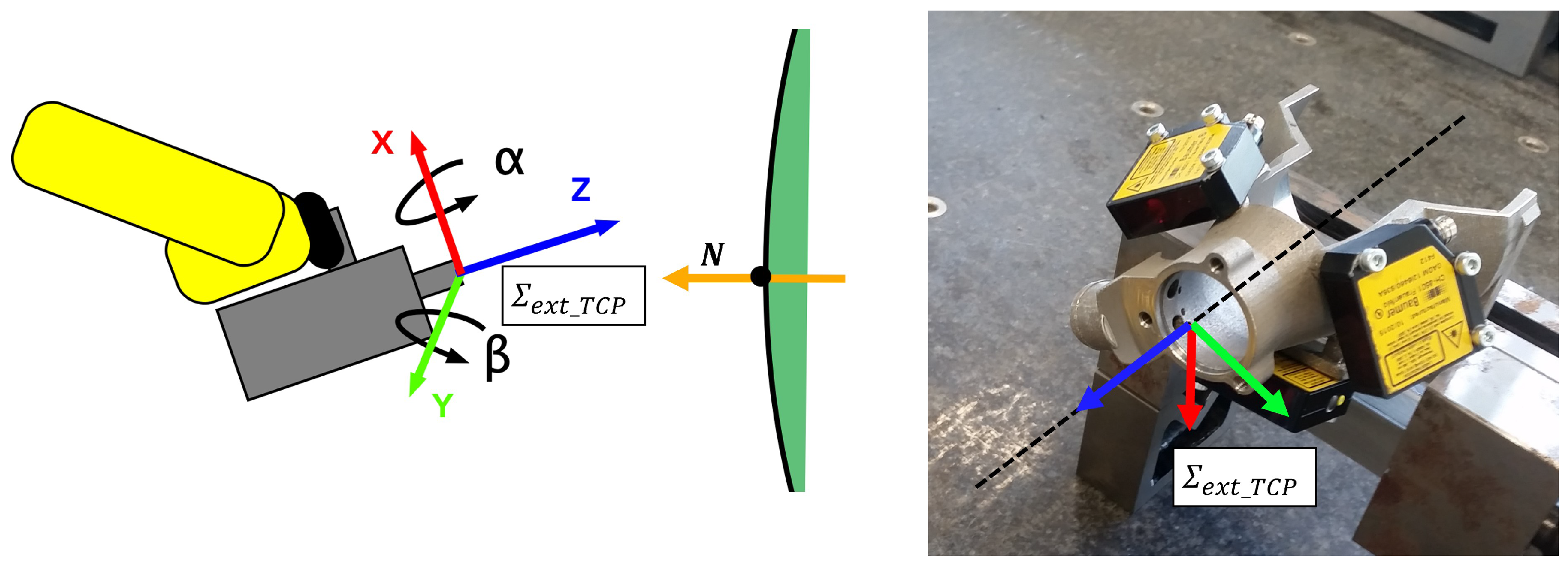
The drilling requirement refers to the maximum angular tolerance between the z-axis of the drilling tool frame, , and the unit vector normal to the panel skin, N, is equal to ±2°, which is required to obtain the correct quality of drilling and countersinking for the installation of fasteners (see Figure 7 on the left).
Based on the distance measurements of the three sensors installed around the drilling nose (see Figure 7 on the right), a triangulation problem was solved to estimate the rotation angles and of Figure 7 on the left, which align the z-axis with N.
Assuming that a general point identified by the laser beam when it intersects a surface has coordinates with respect to its coordinate system (which is known with respect to the robot tool system after a measuring operation with a CNC machine),
and if D is the distance read by the sensor, it is possible to identify a unique plane passing through the three points , , and . The normal vector of this plane, , from which and are calculated, can be written as
3.2. Clamping Force Application
As soon as the drill nose is perpendicular to the panel surface, a thrust force must be applied before the electrospindle is operated to prevent bending or damage to the panel due to local rigidity. This goal is achieved by the simultaneous thrusts of both robots.
In the literature, interaction control strategies can be divided into two categories: indirect force control and direct force control. The main difference is that the former achieves force control via motion control without explicitly closing a force feedback loop, while the latter offers the possibility to control the contact force to a desired value thanks to the closing of a force feedback loop [29]. Considering the presence of a multiaxial torque force sensor attached to the external robot end effector, direct force control systems were chosen.
Initially, we experimented with developing robot force control achieved by closing an external force control feedback loop that generates a positioning control signal that is used as a reference for the robot. This type of control is highly dependent on the contact geometry and the environment. Unfortunately, the available control unit of the robots used in the LABOR work cell does not allow the real-time control of torque and force, but only the implementation of asynchronously sent standard motion commands, so it was impossible to develop a digital implementation of a closed-loop force controller.
An alternative solution has been developed to build up the clamping force by moving the external robot’s drilling tool and the internal robot’s counter-thrust tool in an open circuit until a force threshold is reached. In this way, the control system is not only easier to implement, but also does not require the estimation of many parameters of the previous control scheme (stiffness of the force–torque sensor and the object in contact with the robot, response time of the position-controlled robot, and sampling time of the digital implementation, which are usually required for closed-loop solutions [30]) and it does not require a force–torque sensor for the internal robot. However, with this solution, it must be noted that it does not act on the error and on the continuous feedback of the system output. This means that it is not possible to act on the dynamic performance of the system and that it is not able to reduce the effects of disturbances and measurement noise.
The control strategy assumes that the result of the alignment procedure of Section 3.1 is the one shown in Figure 8a, where the z-axis of the frame is aligned with the vector that is perpendicular to the panel N and passes through the point to be drilled. Assuming that is the origin of the frame, the method only considers robot movements as pure translations along the z-axis of the frame to ensure the alignment itself. Moreover, since the z-axis of the force–torque sensor frame is parallel to the z-axis of the frame, as soon as comes into contact with the surface (under ideal conditions), the forces of interest are only generated along the z-axis of .
The load generated by the contact of the end effector with the panel surface can be modeled by the elastic model and depends on a stiffness coefficient K and is a function of the distance . Assuming that the K is very high, a small translation corresponds to very high force values. For this reason, starting from a situation without contact (Figure 8b), the control strategy uses two translation velocities: the first () allows the robot to move very quickly towards the surface until contact is made (Figure 8c), i.e., until , taking into account only the spatial coordinates along the z-axis; the second () allows the robot to slowly reach the target force (Figure 8e). Note that the strategy provides for the counterforce of the internal robot between the first and second clamping steps to avoid deformation of the panel (Figure 8d).
More precisely, the contact with the surface can be identified by a peak in the force measured by the sensor; therefore, a first force threshold is defined. As soon as , the speed of the end effector is set to 0 with a strong delay. The second preload is performed by the internal robot in the same way. The value of the clamping force is determined with the last thrust of the external robot, which only uses the reduced velocity value as it is already in contact with the surface [28].
3.3. Hole Inspection
The clamping force strategy is followed by the execution of the pure drilling phase, which is carried out according to a specific set of drilling parameters selected by the user. When the hole and the countersink are made, the nose of the end effector moves away from the panel and the external vision system approaches the drilled hole for the inspection step.
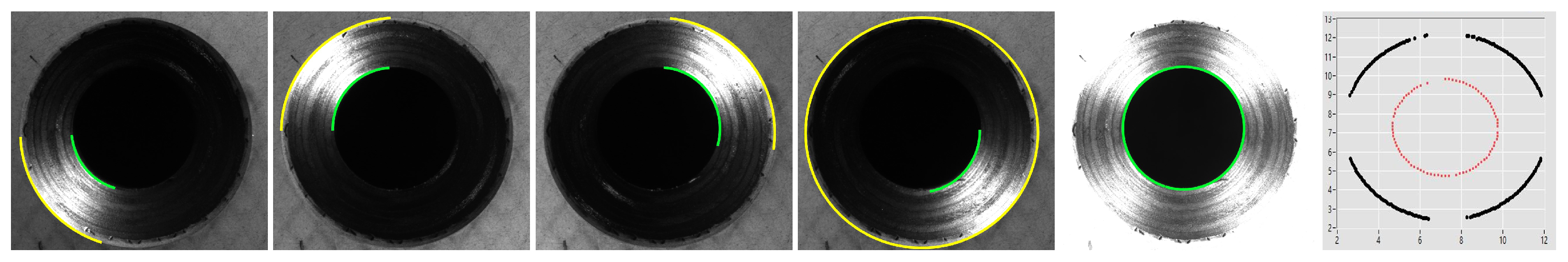
The external end effector is equipped with a camera and four LED projectors. The inner and outer diameters are measured using edge detection analysis. Based on the shape-from-shading technique described in [31], the software performs four acquisitions with only one LED on at a time and a final acquisition with all LEDs on. For each acquisition, the two circular arcs as shown in Figure 9 (yellow external countersink line and green internal hole line) are identified using the contrast variation. The measurement algorithm automatically finds the hole and the countersink in the image, compares the measured diameters with the nominal diameters, and compares the tolerance with that defined in Table 2. Finally, it assesses whether the drilled hole can be accepted; otherwise, the attendance of the operator is required.
3.4. Data Collection for Process Optimization
In line with the Industry 4.0 vision, the LABOR work cell has been equipped with two process optimization analytics that examine the current and potential behaviors of the process using instant data and apply the results to positively influence the process in real time. This means that the system alerts the user when something unusual is happening or targets are not being met, rather than detecting incorrect results after the fact. This improves the process by reacting to real-time data to optimize the overall quality. The two tasks are the grip length measurement and the auto-tuning procedure for the countersink process.
The first task estimates the grip length of the material stack during the drilling process by measuring the distance between the two TCP frames and after the clamping force is applied. This measurement alerts the user interface if the measured grip length does not match the fastener specified in the part program, which would be installed by default.
The second task, which has the same relevance as the first one, is an optional function that allows the LABOR work cell to work in an online controller. The auto-tuning procedure calculates the correct feed rate of the electrospindle based on the history of countersink diameter measurements. As described in Table 4, the electrospindle processes 15 different tips specific to the material stacks and the countersink diameter to be performed. Each tip is associated with a series of calibration parameters that describe the geometric specifications of the tip itself and thus define the geometric advancement that the electrospindle must make to achieve the appropriate countersinking diameter. Each time a hole is drilled with a tip, its set of parameters is not only updated by increasing the number of holes drilled for the evaluation of the average life of the tip itself, but a five-element register is also updated with the measurements of the last five countersink diameters. The auto-tuning algorithm averages these values and estimates the offset value that needs to be added to the calibrated geometric advancement so that the next countersink diameter is closer to the target value. This function is designed to optimize the drilling process and compensate for nose and tip wear, which are mathematically unpredictable, as well as the standard geometric parameters of each tip integrated into a suitable tool holder.
More specifically, the system assumes that each tip has been properly prepared by the operator before inserting it into the LABOR tip warehouse. Then, the assembled part is analyzed by a computer-controlled numerical machine that assigns an ID to the tip, measures the geometric parameters , , , , and , and writes them to the TAG of the tool holder itself. When the user inserts the tip into the tip warehouse—see Figure 10 (right)—a TAG manager reads the specifications and stores them in a software library to identify them when the system uses the tip.
Each tip has an associated from the project requirements that is the target countersink diameter for this tip. The auto-tuning software is based on the Pythagorean theorem and, given the measurement of the current countersink diameter obtained through inspection (see Section 3.3), it calculates the linear stroke that the electrospindle must execute at the next hole to obtain the target diameter . The countersink angle, , is known; thus, the software compares the current height of the countersink, , with the target one, , obtaining the adjustment to be added to the default electrospindle stroke h, i.e.,
This strategy ensures that the next countersink diameters can be in tolerance, by self-correcting the drilling process parameters.
4. Sealing and Fastening Module
The LABOR sealing tool is based on a manual, off-the-shelf sealant gun that has been properly modified to be mounted on the external robot end effector and has been automated by adding a servo-controlled stepper motor to the back of the tool to squeeze the sealant cartridge. The process assumes that the sealant is applied directly to the sleeve of the fastener.
The dispensing of the sealant is a complex process based on several parameters that depend strictly on the specific geometry of the fastener. The flow parameters are linked to the linear movement of the dispensing piston, which regulates the amount of material to be dispensed. Likewise, the axial position in which the rivet is placed is important to correctly place the rivet under the sealant nozzle, more inside or more outside in relation to the rivet head and as required. The system automatically sets the correct parameters by reading both the diameter (DIA) and the grip length (GRIP) of the hole, thus selecting the correct fastener to be installed. In detail, the LABOR work cell can process 7 different types of fasteners, as shown in Table 5.
The fastener is drawn from the fastener warehouse and it is brought under the sealant dispensing nozzle; then, it is spun until a ring of sealant has been applied on it. The external robot brings the fastener to the same position in which it created the hole and inserts it; it then installs it.
4.1. Quality Check
The last step of the system process is the inspection of the installed fastener, both from the internal and the external side.
For the inside, as described in Section 2, the SIT has also been developed for the quality inspection of the installed fasteners in terms of sleeve diameter (requirement ID: H) and sleeve height (requirement ID: G), as described in the requirements of Table 2.
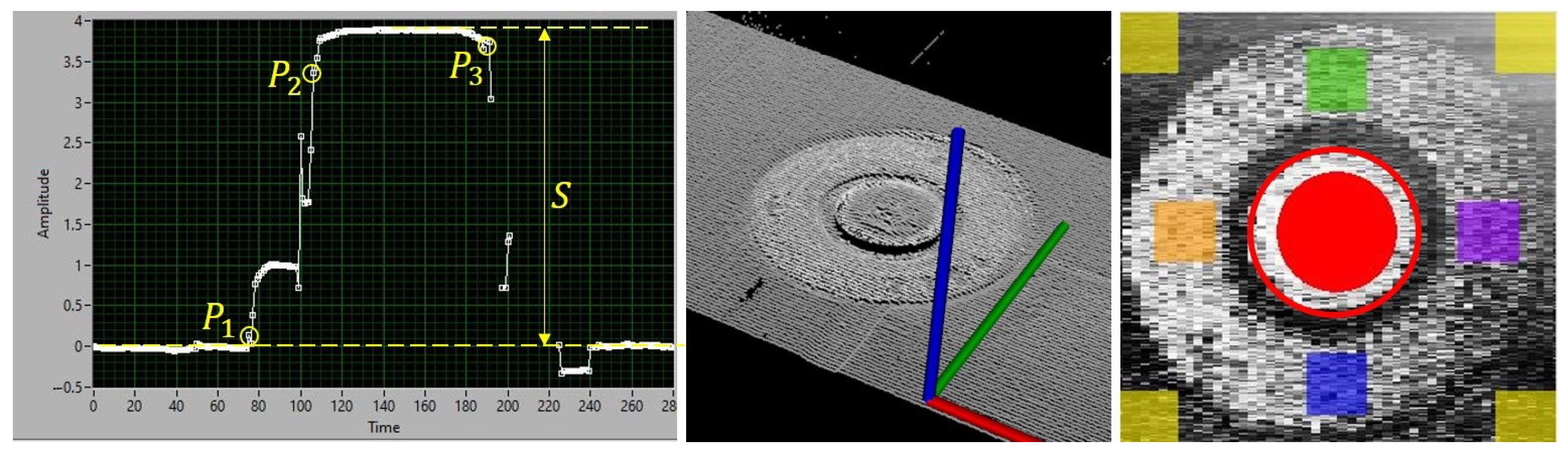
The two profiles extracted from the SIT are combined in a 3D point cloud, which contains a large amount of information that can be elaborated by interpolating geometric units to extract the desired measurement. As shown in Figure 11 on the left, the profile is normalized with respect to the plane to correctly represent the reference plane for the calculation of the height of the fastener. A filter has been applied to compensate for the noise that can lead to false positives. In this way, the starting point of the base crown of the fastener () and the starting point () and end point () of the fastener head were identified. The sleeve height corresponds to the highest point of the bolt profile between and , while the sleeve diameter was calculated as follows:
From the external side, however, the inspection algorithm measures the stem protrusion (requirement ID: E) and the flushness (requirement ID: F) of Table 2. In essence, the technique identifies some regions of interest (ROI) on the grayscale image of Figure 11 on the right, obtained by the captured 3D point cloud intensities (Figure 11 center). First, the software calculates the stem protrusion, i.e., the maximum allowable distance from the top of land on the stem to the fastener head surface. To do this, the software identifies the edge of the stem (red circumference), within which a smaller red circular ROI has been defined, which represents the center of the stem. The median of the heights of all points within the red circle is calculated. At the same time, the software identifies four ROIs (green, orange, blue, and purple) on the fastener land surface, and then calculates the median of the heights of all points within these ROIs. The stem protrusion is obtained from the difference between these two values.
The second dimension, the flushness, is the maximum allowable distance from the top of land on the stem to the panel skin. It is assumed that the panel skin is locally flat, and it was calculated by identifying four yellow ROIs at the corner points of the captured image. The software calculates the median of the heights of the points within these areas and compares the mean value to the value representing the surface of the fastener calculated above.
5. HRC Module
Nowadays, collaborative robotics are one of the main topics of Industry 5.0 [32]: robots and workers share the workspace thanks to the use of small and safe robots, the so-called cobots. However, when the task requires particularly high precision or load for cobots, or a particular level of human dexterity and decision-making ability, the LABOR HRC module becomes indispensable to allow both industrial robots and workers to share the workspace, to save time and improve productivity while maintaining human safety [33]. As described in Section 1.5, the work cycle of the side FWD panel requires manual assembly activities that can be performed together with a human operator, as shown in Table 3. The HRC module includes the novel multimodal perception system, whose laboratory test bench is shown in Figure 12A. The tracking method of the human sharing the workspace with a robot is based on the fusion of depth and thermal images. A machine learning approach was followed to develop a novel CNN that achieves reliable detection performance in collaborative systems with multiple humans (see Section 5.1). The detected human was used to implement the SSM collaboration scenario, which controls the speed of the robot according to the current hazardous situation, enabling real-time risk assessment (see Section 5.2). The module proposes a novel fuzzy inference approach to control the robot speed, which increases the safety while maximizing the robot’s productivity level by minimizing robot stops.
5.1. Human Detection and Tracking
The CNN was trained with images obtained through a novel sensor fusion strategy that fused spatial and thermal data to robustly identify human workers. While the most widely used image fusion algorithms [34] combine the information sources into a single grayscale image with suitable weights defined by the user, here, the depth and thermal data are combined with the goal of preserving the integrity of the information contained in the two sources. The algorithm assigns the entire thermal image to the R (red) channel of an empty RGB image, and the entire depth image is assigned to the G (green) channel of the same RGB image. More precisely, the original value of the depth sensor, , and the corresponding value of the temperature sensor, , were normalized according to a predefined interval. Specifically, for the thermal camera, this means °C and °C, which represent the temperature interval for detection of the human surface; for the depth camera, m and m, which define the depth range of the sensor. At this point, the color information that is inserted into the specific channel of the -th pixel of the output image must be mapped to 8 bits. The (red) value is calculated by capturing from the thermal image as
the (green) value is computed by acquiring from the depth image
the B (blue) value of the resulting image is always zero. The resulting image is shown in Figure 12B and it has been used for real-time human detection, solved through the use of the framework YOLOv3 [35]. After the definition of a Human class, a training dataset has been built to retrain the YOLOv3 CNN and obtain the correct estimated weights. See [33] for further details on the performance of human detection and tracking.
In contrast to the pre-trained standard RGB CNNs and the single-source CNNs that can confuse objects with human-like shapes or temperatures similar to humans, this CNN produces a very low percentage of false positives (2.7% as reported in [33]), as shown in Figure 12B, where a plastic mannequin is not identified as human. In this way, the speed scaling algorithm (Section 5.2) does not generate unnecessary robot stops and thus maximizes the production time. The software is able to identify multiple human workers who are in the scene at the same time. The two closest points are identified, one belonging to the robot, , and one to the identified worker closest to the robot, , as shown in Figure 12C. The effective separation distance d is calculated from these points.
5.2. Speed and Separation Monitoring
The robot speed control system uses fuzzy inference logic that scales the robot’s nominal velocity according to some heuristic considerations that estimate the degree of danger to the worker, in Equation (7). The fuzzy inference logic reasons about
- the time derivative of the distance between human and robot, i.e., ;
- the scalar product between the velocity vectors of the robot and the human, i.e., ;
- the temperature value of the human point at the minimum distance from the robot.
The first input is useful to distinguish when the operator and the robot are moving closer () and when they are moving away from each other (). The second input specifies whether the travel directions of the operator and the robot are aligned () or opposite (). The third input relaxes the speed monitoring if the point closest to the robot belongs to a non-human surface, providing a reduction in the production time. See [33] for further details on the design of the fuzzy inference system.
The control system computes the minimum protective distance S of the SSM scenario described in ISO15066 [16]:
where is the time required by the system to identify the operator, is the time required for a complete robot stop, C is the intrusion distance, and are the robot and the human position uncertainties, and B is the Euclidean distance travelled by the robot while braking. While the standard Equation (7) does not foresee (i.e., ), the LABOR approach introduces , representing a scaling factor, which evaluates the current risk assessment analysis: as explained in [36], the robot speed override k is computed by comparing d and S, obtaining a smooth robot speed change (from 0% to 100% of the nominal velocity, not simply pre-defined speed levels) for a psychological advantage for operators [37]. Moreover, the adopted solution (7) considers the current and rather than fixed values.
6. Results
In this section, the final results of the LABOR assembly process are presented and analyzed.
6.1. Experimental Setting and Procedure
As described in Section 1.2, the side FWD panel shown in Figure 2 (right) was taken as a demonstrative reference to analyze and prove the qualitative and quantitative results of the proposed robot assembly strategy. The reason for this is that, unlike other panels that do not require human intervention, the side FWD panel represents the most complex experimental setup, as some of its parts need to be assembled manually. Therefore, the process alternates fully automated work phases with HRC tasks, during which it is possible to demonstrate the performance of the collaborative solution described in Section 5. Note that the collected results aim at illustrating the performance of the software solutions developed for each individual module by showing their benefits in each assembly subprocess. In this view, the section shows how the work cell globally overcomes the drawbacks and limitations of the existing solutions discussed in Section 1.1.
The referencing algorithm was performed on two short shear-ties, proving that no external measuring device is required, as the SIT and the developed image processing strategy are sufficient to calculate the actual part pose and obtain the correct hole positioning. The drilling results show the accuracy and repeatability of the hole and countersinking diameters determined by the work cell for a long shear-tie assembly consisting of 27 holes. The fastening results show the vision measurements of 11 fasteners installed by the LABOR work cell to a short shear-tie. Figure 13 shows a section of the collaborative task: the corresponding digital twin of the work cell is shown in the top right, in which the thermal point cloud of the human operator identified by the multimodal CNN can be seen. The bottom right shows the approach used to modulate the robot speed. Note that the results of the HRC task have not been reported as they have already been published and analyzed in detail in a previous work [13].
6.2. Referencing and Hole Positioning Results
Two short shear-ties with seven holes (see Table 1) have been chosen to show that the LABOR work cell does not need another expensive external measuring device for the correct positioning of the holes, as it is equipped with the SIT that performs the referencing step.
If the part to be drilled has not been correctly positioned at its target position on the panel, errors in the positioning of the holes can occur, which is practically always the case when the parts are manually glued by human operators. The result underlines the need to adjust the part pose with respect to the panel through the referencing step. As indicated in the technical specifications of the project, it is important to measure the distances between the holes and the distances between the edges of the holes and the edges of the parts in order to evaluate the accuracy of the positioning of the holes.
Two examples are described below for comparison. The data were collected by scanning the part after drilling, as shown in Figure 14.
The most common result of drilling a part that has never been referenced before is a pattern that is not aligned with the longer edge of the shear-tie but is instead shifted and rotated, which is a normal effect of the rough manual positioning of the part. This is the result of the first shear-tie, which has not been referenced before the drilling step, as seen in Table 6. Note that the spacing within the hole is within tolerance, but the pattern is completely misaligned compared to the nominal one.
On the other hand, the 3D reconstruction of the second shear-tie’s actual local reference frame in comparison to its nominal one reveals that the part has been slightly translated and rotated from its nominal pose.
Repeating the same measurements as for the first shear-tie, Table 7 shows that the referencing step becomes mandatory for assembly processes with strict tolerances that are usually less than 0.5 tenths of a millimeter.
6.3. Drilling Results
In this section, we present examples of tests that show the accuracy and repeatability of the hole and countersink diameters produced by LABOR and measured with the proposed SIT vision system.
To prove the accuracy of the LABOR holes, the measurements calculated with the SIT are compared with those of the TRULOK digital gauge, which is used in the aerospace industry for the fast and accurate measurement of countersink and hole depths (measurement accuracy: 0.005 mm). A set of 50 hole samples is analyzed. The difference between the two measurement systems for hole diameter measurement is 0.0258 mm on average, with repeatability of ±0.015 mm, which is below the design tolerance of ±0.025 mm. The difference between the two measurement systems for countersink diameter measurement is 0.0174 mm on average, with repeatability of 0.071 mm, less than the design tolerance of 0.085 mm. The test shows that the proposed non-contact inspection system is highly interchangeable with the manual system, with the advantage that no errors can be made in the use of the instrument during the measurement that affect the measurement. The measurements performed with the TRULOK during the test have been carried out on a flat panel drilled by LABOR and positioned rigidly on a shelf. Normally, however, the measurement is made manually by a human operator working directly on the curved element glued to the curved fuselage panel: the measurement error could be very high due to the incorrect use of the instrument and the proposed inspection instrument has much higher accuracy.
To demonstrate the hole and countersink precision, 50 samples have been inspected by using a high-accuracy laser tracker. Table 8 shows three tests:
- T01: hole diameter accuracy;
- T02: countersink angle accuracy;
- T03: normality alignment.
Finally, a practical assembly demonstration is reported. A long shear-tie of the side FWD panel, composed of 27 holes (see Table 1), was selected to analyze the drilling measurement performance of the LABOR work cell. Table 9 collects the measurements of the requirements of Table 2, which are defined by IDs B, C, and D. The material stack (ID A of Table 2) is CT, while the holes are defined with DIA06-GRIP04; therefore, the system selects LABT24 for the electrospindle according to Table 4. The hole diameters (column B) meet the requirements for about 89%, as well as the countersink diameters (column C). In addition, the grip length (column D) shows no outliers.
6.4. Fastening Results
A short shear-tie of the side FWD panel, composed of 11 holes (see Table 5), was selected to report the results of the fastening process. Table 10 collects the measurements of the requirements of Table 2, which are defined by the IDs E, F, G, and H. The material stack (ID A of Table 2) is CT, while the holes are defined with DIA06-GRIP04; therefore, the system selects FAST03 as the fastener type according to Table 5.
After analyzing the outside of the installed fastener, both the stem protrusion (requirement ID: E) and the flushness (requirement ID: F) meet the project requirements without any outliers. The analysis of the inside of the fastener, which is performed by calculating the sleeve height and the sleeve diameter, also leads to the same result. This is a typical result of the system in relation to the requirement IDs F and G, which represents the correct and careful parameterization of both the involved thrust forces and the calibration accuracy of the work cell.
7. Conclusions
This article describes the main software implementations and the final process parameters of the LABOR robotic work cell and collects the experimental results on a full-scale demonstrator. In detail, the advantages of the solution compared to the state of the art are demonstrated and the innovative algorithms proposed here are presented, as well as the approaches developed to optimize each phase of the operations to be performed, i.e., drilling, sealing, fastening, and inspection, all in the presence of the human operator when required by the work cycle. The solutions developed are presented taking into account the project requirements to demonstrate the high accuracy achieved by integrating the distributed architecture into the new concept of lean automation with the use of small–medium-sized robots. The result is a robotic cell that optimizes the assembly process with a time saving of 30%, calculated without taking into account the time for the inspection phase, and with more precise and accurate measurement results compared to the traditional manual assembly process. A video showing the main features of the LABOR cell is available online: https://images.loccioni.com/Share/142d68f4-49f9-4b46-bb96-621e3440042b (accessed on 21 January 2024). The solution looks to the future with concrete industrial automation possibilities, although some hardware improvements are still necessary.
The most important problems are described below, together with possible solutions that have not yet been implemented in this demonstration prototype. When higher than the minimum required loads are applied to the tip during the clamping phase, the nose of the drilling end effector tends to slide on the outer surface of the panel, shifting slightly with respect to the actual target position. A possible solution could be to replace the metal nose with a material with greater friction. In addition, the robustness of the hardware of the mounting module should be improved. Indeed, the feeding mechanism of the rivets sometimes does not work properly, although this occurs rarely, either because the rivets become stuck in the drawer or because the air flow pushing them to the tip of the end effector does not guarantee the perfect alignment of the fastener in the vice. One possible solution would be a commercial feeding system that is integrated into the cell.
The future work plan is to 3D print some prototypes of drill noses made of different materials and with different geometries of the contact surface. The basic idea is to develop noses made of thermoplastic material (so-called DELRIN) and rubber gaskets with different frictional properties, which will be applied to the nose to improve the stability of the contact surface with the panel. On the other hand, a vibration system is planned to facilitate the sliding of the fasteners in the drawer guides so that they do not become stuck. Finally, the replacement of the tubes connecting the drawers of the rivet magazine to the end effector is planned: they will be replaced with tubes of a specific diameter, depending on the size of the fastener that they support, to prevent them from tipping over during transportation.
Author Contributions
Conceptualization, G.L. and C.N.; methodology, G.L. and C.N; software, G.L.; validation, G.L.; writing—original draft preparation, G.L.; writing—review and editing, G.L. and C.N.; visualization, G.L.; supervision, C.N.; project administration, C.N.; funding acquisition, C.N. All authors have read and agreed to the published version of the manuscript.
Funding
This work has received funding from the European Commission within the Clean Sky Horizon 2020 Programme under the LABOR project, GA n. 785419.
Informed Consent Statement
Informed consent was obtained from all subjects involved in the study.
Data Availability Statement
Data available on request due to confidentiality restrictions.
Conflicts of Interest
The authors declare no conflicts of interest.
References
- The LABOR Project. Available online: https://www.labor-project.eu/ (accessed on 19 November 2023).
- Xu, X.; Lu, Y.; Vogel-Heuser, B.; Wang, L. Industry 4.0 and Industry 5.0—Inception, conception and perception. J. Manuf. Syst. 2021, 61, 530–535. [Google Scholar] [CrossRef]
- Global Market Forecast 2019–2038. Available online: https://www.airbus.com/aircraft/market/global-market-forecast.html (accessed on 19 November 2023).
- Airbus Inaugurates New A320 Structure Assembly Line in Hamburg. Available online: https://www.airbus.com/en/newsroom/press-releases/2019-10-airbus-inaugurates-new-a320-structure-assembly-line-in-hamburg (accessed on 19 November 2023).
- Bombardier to Combine Efficiency and Quality in Manufacturing of CSeries Aircraft. Available online: https://bombardier.com/en/media/news/bombardier-combine-efficiency-and-quality-manufacturing-cseries-aircraft (accessed on 19 November 2023).
- A Futuristic View of the 777 Fuselage Build. 2014. Available online: http://www.boeing.com/features/2014/07/bca-777-fuselage-07-14-14.page (accessed on 19 November 2023).
- The VALERY Project. Available online: https://cordis.europa.eu/project/id/314774 (accessed on 19 November 2023).
- Petzoldt, C.; Harms, M.; Freitag, M. Review of task allocation for human-robot collaboration in assembly. Int. J. Comput. Integr. Manuf. 2023, 36, 1675–1715. [Google Scholar] [CrossRef]
- Tsarouchi, P.; Matthaiakis, A.S.; Makris, S.; Chryssolouris, G. On a human-robot collaboration in an assembly cell. Int. J. Comput. Integr. Manuf. 2016, 30, 580–589. [Google Scholar] [CrossRef]
- Kumar, S.; Savur, C.; Sahin, F. Survey of Human–Robot Collaboration in Industrial Settings: Awareness, Intelligence, and Compliance. IEEE Trans. Syst. Man, Cybern. Syst. 2021, 51, 280–297. [Google Scholar] [CrossRef]
- Sipsas, K.; Nikolakis, N.; Makris, S. Dynamic Assembly Planning and Task Assignment. In Advanced Human-Robot Collaboration in Manufacturing; Springer International Publishing: Berlin/Heidelberg, Germany, 2021; pp. 183–210. [Google Scholar] [CrossRef]
- Bejarano, R.; Ferrer, B.R.; Mohammed, W.M.; Martinez Lastra, J.L. Implementing a Human-Robot Collaborative Assembly Workstation. In Proceedings of the 2019 IEEE 17th International Conference on Industrial Informatics (INDIN), Helsinki, Finland, 22–25 July 2019. [Google Scholar] [CrossRef]
- Caterino, M.; Chiacchio, P.; Cristalli, C.; Fera, M.; Lettera, G.; Natale, C.; Nisi, M. Robotized assembly and inspection of composite fuselage panels: The LABOR project approach. IOP Conf. Ser. Mater. Sci. Eng. 2021, 1024, 012019. [Google Scholar] [CrossRef]
- ISO 10218-1; Robots and Robotic Devices—Safety Requirements for Industrial Robots. Part 1: Robots. International Organization for Standardization: Geneva, Switzerland, 2011.
- ISO 10218-2; Robots and Robotic Devices—Safety Requirements for Industrial Robots. Part 2: Robot System and Integration. International Organization for Standardization: Geneva, Switzerland, 2011.
- ISO/TS 15066; Robots and Robotic Devices—Collaborative Robots. International Organization for Standardization: Geneva, Switzerland, 2016.
- Yan, W.; Bi, Y.; Qiao, M. Effect of positioning errors of frames on fuselage panel assembly deformation. Adv. Mech. Eng. 2016, 8, 168781401665056. [Google Scholar] [CrossRef]
- Bruni, A.; Concettoni, E.; Cristalli, C.; Nisi, M. Smart Inspection Tools in robotized aircraft panels manufacturing. In Proceedings of the 2019 IEEE 5th International Workshop on Metrology for AeroSpace (MetroAeroSpace), Turin, Italy, 19–21 June 2019. [Google Scholar] [CrossRef]
- Baeg, M.H.; Baeg, S.H.; Moon, C.; Jeong, G.M.; Ahn, H.S.; Kim, D.H. A New Robotic 3D Inspection System of Automotive Screw Hole. Int. J. Control. Autom. Syst. 2008, 6, 740–745. [Google Scholar]
- Spagnolo, G.S.; Cozzella, L.; Leccese, F. Viability of an optoelectronic system for real time roughness measurement. Measurement 2014, 58, 537–543. [Google Scholar] [CrossRef]
- 8-Tree. Available online: https://www.8-tree.com/ (accessed on 19 November 2023).
- UnitedScience. Available online: https://unitedsciences.com/ (accessed on 19 November 2023).
- Hocken, R.; Chakraborty, N.; Brown, C. Optical Metrology of Surfaces. CIRP Ann. 2005, 54, 169–183. [Google Scholar] [CrossRef]
- Besl, P.; McKay, N.D. A method for registration of 3-D shapes. IEEE Trans. Pattern Anal. Mach. Intell. 1992, 14, 239–256. [Google Scholar] [CrossRef]
- Castellini, P.; Bruni, A.; Paone, N. Design of an optical scanner for real time on-line measurement of wood-panel profiles. In Proceedings of the Optical Measurement Systems for Industrial Inspection V, Munich, Germany, 17–21 June 2007. [Google Scholar] [CrossRef]
- Marrazzo, A. Kinematic Calibration and Human-Machine Interface for a Cooperative Robotic Work Cell. Master’s and Specialist Thesis, Università Degli Studi di Salerno, Fisciano, Italy, 2018. Available online: https://hdl.handle.net/20.500.12074/13026 (accessed on 19 November 2023).
- Toquica, J.S.; Motta, J.M.S.T. A methodology for industrial robot calibration based on measurement sub-regions. Int. J. Adv. Manuf. Technol. 2021, 119, 1199–1216. [Google Scholar] [CrossRef]
- Domenico, F.D. Force-Based Control for Robotic Drilling of Aeronautical Structures. Master’s and Specialist Thesis, Università Degli Studi di Salerno, Fisciano, Italy, 2018. Available online: https://hdl.handle.net/20.500.12074/13032 (accessed on 19 November 2023).
- Siciliano, B.; Villani, L. Robot Force Control; 1999 ed.; The Springer International Series in Engineering and Computer Science; Springer: Dordrecht, The Netherlands, 2000. [Google Scholar]
- Marino, A.; Cirillo, P.; Natale, C.; Chiacchio, P.; Pirozzi, S. A general low-cost and flexible architecture for robotized drilling in aircraft assembly lines. In Proceedings of the 2016 International Symposium on Power Electronics, Electrical Drives, Automation and Motion (SPEEDAM), Capri, Italy, 22–24 June 2016; pp. 1401–1408. [Google Scholar] [CrossRef]
- Zhang, R.; Tsai, P.S.; Cryer, J.; Shah, M. Shape-from-shading: A survey. IEEE Trans. Pattern Anal. Mach. Intell. 1999, 21, 690–706. [Google Scholar] [CrossRef]
- Demir, K.; Doven, G.; Sezen, B. Industry 5.0 and Human-Robot Co-working. Procedia Comput. Sci. 2019, 158, 688–695. [Google Scholar] [CrossRef]
- Costanzo, M.; Maria, G.D.; Lettera, G.; Natale, C. A Multimodal Approach to Human Safety in Collaborative Robotic Workcells. IEEE Trans. Autom. Sci. Eng. 2022, 19, 1202–1216. [Google Scholar] [CrossRef]
- Yang, B.; Jing, Z.-L.; Zhao, H.-T. Review of pixel-level image fusion. J. Shanghai Jiaotong Univ. (Sci.) 2010, 15, 6–12. [Google Scholar] [CrossRef]
- Redmon, J.; Farhadi, A. YOLOv3: An Incremental Improvement. arXiv 2018, arXiv:1804.02767. [Google Scholar]
- Campomaggiore, A.; Costanzo, M.; Maria, G.D.; Lettera, G.; Natale, C. A Fuzzy Inference Approach to Control Robot Speed in Human-robot Shared Workspaces. In Proceedings of the 16th International Conference on Informatics in Control, Automation and Robotics, Prague, Czech Republic, 29–31 July 2019; pp. 78–87. [Google Scholar]
- Lu, L.; Xie, Z.; Wang, H.; Li, L.; Xu, X. Mental stress and safety awareness during human-robot collaboration—Review. Appl. Ergon. 2022, 105, 103832. [Google Scholar] [CrossRef] [PubMed]
Figure 1.
Distributed software architecture.

Figure 2.
Final fuselage details: AFT and FWD panels and side, keel, and crown sections (left); side forward panel structural arrangement (right).
Figure 2.
Final fuselage details: AFT and FWD panels and side, keel, and crown sections (left); side forward panel structural arrangement (right).

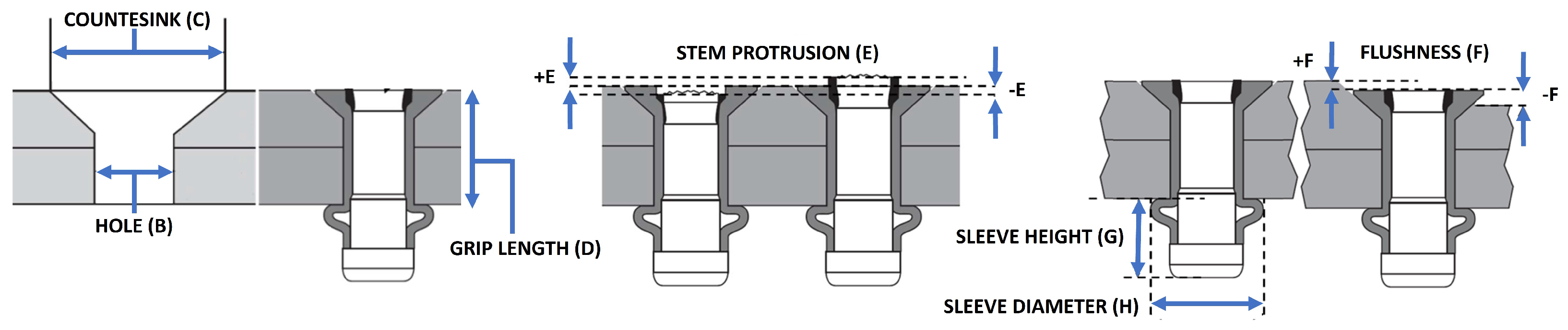
Figure 3.
Identification of drilling and fastener measurement requirements.

Figure 4.
Example of a HRC assembly operation: the operator removes the blue element from the panel for the execution of deburring operations, while the robot executes inspection of other parts.
Figure 4.
Example of a HRC assembly operation: the operator removes the blue element from the panel for the execution of deburring operations, while the robot executes inspection of other parts.

Figure 5.
Work cell calibration of the system (left) and referencing of the part with respect to the internal vision system (right).
Figure 5.
Work cell calibration of the system (left) and referencing of the part with respect to the internal vision system (right).

Figure 6.
Referencing algorithms: edge detection for shear-tie (left) and pop-rivet identification for stringer and frames (right).
Figure 6.
Referencing algorithms: edge detection for shear-tie (left) and pop-rivet identification for stringer and frames (right).

Figure 7.
Drilling alignment requirement: align the z-axis of the drilling tool frame, , with the unit vector normal to the panel skin, N (left), of the drilling nose (right).
Figure 7.
Drilling alignment requirement: align the z-axis of the drilling tool frame, , with the unit vector normal to the panel skin, N (left), of the drilling nose (right).

Figure 8.
Clamping force strategy: once the external robot end effector has been aligned with the panel surface (a), it executes a pure translation towards the surface (b) until contact occurs (c); then, it waits for the counter-thrust application from the internal robot (d) before starting the second clamping step until the target force has been reached (e).

Figure 9.
Hole and countersink diameter measurement: the two arcs of the circumference have been identified from five acquisitions, the yellow one representing the external countersink edge and the green one representing the internal hole edge. The final reconstruction that merges the segments identified in each picture is shown on the right.

Figure 10.
Hole and countersink diameter measurement.

Figure 11.
Fastener quality check: from the internal side (left) the software computes the sleeve diameter and the sleeve height by identifying three representative points, while from the external side (center and right) it computes the stem protrusion and the flushness by identifying some representative ROIs (colored areas).

Figure 12.
The HRC test bench: the laboratory collaborative workspace setup (A); the robust human detection of the CNN through the novel sensor fusion approach (B); several human workers identified in the scene at the same time (C); two identified closest points for separation distance computation (D).

Figure 13.
The HRC algorithm integrated into the LABOR work cell: a frame of the collaborative task, on the left; the corresponding digital twin, which shows the point cloud of the human operator identified by the multimodal CNN, on the top right; the robot speed modulation approach, on the bottom right.

Figure 14.
Hole positioning analysis: distance measurements between holes and between the hole edges and the part edges.
Figure 14.
Hole positioning analysis: distance measurements between holes and between the hole edges and the part edges.


Table 1.
Side forward panel: number of elements and holes.
| Element Name | Cardinality | Element Holes |
|---|---|---|
| Short shear-tie | 4 | 8 |
| Short shear-tie | 8 | 6 |
| Short shear-tie | 6 | 7 |
| Short shear-tie | 3 | 11 |
| Long shear-tie | 3 | 27 |
| Stringer | 6 | 46 |
| Stringer | 6 | 74 |
| Frame | 2 | 78 |
Table 2.
Manufacturing requirements (measurement units have been omitted for confidentiality reasons).
Table 2.
Manufacturing requirements (measurement units have been omitted for confidentiality reasons).
| ID Requirement | Description | Target Value |
|---|---|---|
| A | Material stack | CT: CFRP + Thermoplastic |
| CC: CFRP + CFRP | ||
| CA: CFRP + Aluminium | ||
| B | Hole nominal diameters | DIA05: [4.166, 4.242] mm |
| DIA06: [5.055, 5.131] mm | ||
| DIA08: [6.604, 6.680] mm | ||
| DIA10: [4.826, 4.902] mm | ||
| DIA20: [6.350, 6.426] mm | ||
| C | Countersink nominal diameters | DIA05: [8.331, 8.458] mm |
| DIA06: [9.677, 9.804] mm | ||
| DIA08: [12.750, 12.878] mm | ||
| DIA10: [9.677, 9.804] mm | ||
| DIA20: [12.750, 12.878] mm | ||
| D | Grip length | GRIP03: [3.962, 5.588] mm |
| GRIP04: [5.563, 7.163] mm | ||
| GRIP05: [7.137, 8.763] mm | ||
| GRIP06: [8.738, 10.338] mm | ||
| E | Stem protrusion | DIA05: ±0.254 mm |
| DIA06: ±0.305 mm | ||
| DIA08: ±0.381 mm | ||
| DIA10: ±0.305 mm | ||
| DIA20: ±0.381 mm | ||
| F | Flushness | ±0.203 mm |
| G | Maximum sleeve height | 5.9 mm |
| H | Minimum sleeve diameter | 5.7 mm |
Table 3.
General aircraft panel assembling operations without and with HRC.
| WITHOUT HRC | WITH HRC | |||
|---|---|---|---|---|
| OP CODE | HUMAN | ROBOT | HUMAN | ROBOT |
| OP10 | Part assembly on SFRP skin | NA | Part assembly on SFRP skin | NA |
| OP20 | Panel drilling | NA | NA | Panel drilling |
| OP30 | Panel countersinking | NA | NA | Panel countersinking |
| OP40 | Hole inspection | NA | NA | Hole inspection |
| OP50 | Stringer de-assembling | NA | Stringer de-assembling | NA |
| OP60 | Stringer cleaning | NA | Stringer cleaning | NA |
| OP70 | Stringer deburring | NA | Stringer deburring | NA |
| OP80 | Sealant application | NA | Sealant application | NA |
| OP90 | Stringer re-assembling | NA | Stringer re-assembling | NA |
| OP100 | Panel riveting | NA | NA | Panel riveting |
Table 4.
Electrospindle tip types.
| Diameter | CFRP + Aluminium | CFRP + CFRP | CFRP + Thermoplastic |
|---|---|---|---|
| DIA10 | LABT01 | LABT11 | LABT21 |
| DIA20 | LABT02 | LABT12 | LABT22 |
| DIA05 | LABT03 | LABT13 | LABT23 |
| DIA06 | LABT04 | LABT14 | LABT24 |
| DIA08 | LABT05 | LABT15 | LABT25 |
Table 5.
Fastener types.
| Diameter | Grip Length | Fastener ID |
|---|---|---|
| DIA05 | GRIP04 | FAST01 |
| DIA06 | GRIP03 | FAST02 |
| DIA06 | GRIP04 | FAST03 |
| DIA06 | GRIP05 | FAST04 |
| DIA06 | GRIP06 | FAST05 |
| DIA08 | GRIP06 | FAST06 |
| DIA08 | GRIP07 | FAST07 |
Table 6.
NOK hole positioning result: the holes have been made without a previous part referencing step.
Table 6.
NOK hole positioning result: the holes have been made without a previous part referencing step.
| Distance | Nominal | Measured | Tolerance | Deviation | Check |
|---|---|---|---|---|---|
| C1-C2 | 25.490 | 25.467 | ±0.400 | −0.025 | √ |
| C2-C3 | 25.490 | 25.527 | ±0.400 | 0.037 | √ |
| C3-C4 | 25.490 | 25.144 | ±0.400 | −0.346 | √ |
| C4-C5 | 25.490 | 25.841 | ±0.400 | 0.351 | √ |
| C5-C6 | 25.490 | 25.758 | ±0.400 | 0.268 | √ |
| C1-mE | 13.500 | 20.137 | ±0.400 | 6.637 | |
| C1-ME | 13.500 | 11.167 | ±0.400 | −2.333 | |
| C2-ME | 13.500 | 11.779 | ±0.400 | −1.721 | |
| C3-ME | 13.500 | 11.978 | ±0.400 | −1.522 | |
| C4-ME | 13.500 | 12.004 | ±0.400 | −1.496 | |
| C5-ME | 13.500 | 12.210 | ±0.400 | −1.290 | |
| C6-ME | 13.500 | 12.945 | ±0.400 | −0.555 |
Table 7.
OK hole positioning result: the holes have been made after a previous part referencing step.
Table 7.
OK hole positioning result: the holes have been made after a previous part referencing step.
| Distance | Nominal | Measured | Tolerance | Deviation | Check |
|---|---|---|---|---|---|
| C1-C2 | 25.490 | 25.888 | ±0.400 | 0.358 | √ |
| C2-C3 | 25.490 | 25.414 | ±0.400 | −0.076 | √ |
| C3-C4 | 25.490 | 25.597 | ±0.400 | 0.107 | √ |
| C4-C5 | 25.490 | 25.461 | ±0.400 | −0.029 | √ |
| C5-C6 | 25.490 | 25.595 | ±0.400 | 0.105 | √ |
| C6-C7 | 25.490 | 25.589 | ±0.400 | 0.099 | √ |
| mE-C1 | 13.500 | 13.328 | ±0.400 | −0.172 | √ |
| C1-ME | 13.500 | 13.208 | ±0.400 | −0.292 | √ |
| C2-ME | 13.500 | 13.046 | ±0.400 | −0.354 | √ |
| C3-ME | 13.500 | 13.185 | ±0.400 | −0.315 | √ |
| C4-ME | 13.500 | 13.126 | ±0.400 | −0.374 | √ |
| C5-ME | 13.500 | 13.233 | ±0.400 | −0.267 | √ |
| C6-ME | 13.500 | 13.288 | ±0.400 | −0.212 | √ |
| C7-ME | 13.500 | 13.232 | ±0.400 | −0.268 | √ |
Table 8.
Drilling accuracy and repeatability tests.
| Test ID | Nominal | Measured | Tolerance | Deviation | Check |
|---|---|---|---|---|---|
| T01 | 5.100 mm | 5.085 mm | ±0.038 mm | 0.0150 mm | √ |
| T02 | 130° | 129.590° | ±1° | 0.410° | √ |
| T03 | 90° | 89.171° | ±2° | 0.829° | √ |
Table 9.
Drilling measurement checks.
| Hole ID | B | Check B | C | Check C | D | Check D |
|---|---|---|---|---|---|---|
| F001 | 5.083 | √ | 9.762 | √ | 5.772 | √ |
| F002 | 5.084 | √ | 9.770 | √ | 5.714 | √ |
| F003 | 5.082 | √ | 9.788 | √ | 5.784 | √ |
| F004 | 5.081 | √ | 9.800 | √ | 5.709 | √ |
| F005 | 5.083 | √ | 9.755 | √ | 5.922 | √ |
| F006 | 5.013 | 9.774 | √ | 5.624 | √ | |
| F007 | 5.066 | √ | 9.763 | √ | 5.482 | √ |
| F008 | 5.077 | √ | 9.733 | √ | 6.760 | √ |
| F009 | 5.074 | √ | 9.687 | √ | 6.478 | √ |
| F010 | 5.084 | √ | 9.687 | √ | 6.055 | √ |
| F011 | 5.069 | √ | 9.683 | √ | 5.952 | √ |
| F012 | 5.068 | √ | 9.674 | 5.783 | √ | |
| F013 | 5.062 | √ | 9.677 | √ | 5.421 | √ |
| F014 | 5.074 | √ | 9.763 | √ | 5.561 | √ |
| F015 | 5.067 | √ | 9.763 | √ | 5.499 | √ |
| F016 | 5.004 | 9.778 | √ | 5.130 | √ | |
| F017 | 5.086 | √ | 9.742 | √ | 5.875 | √ |
| F018 | 5.083 | √ | 9.804 | √ | 6.247 | √ |
| F019 | 5.076 | √ | 9.737 | √ | 6.142 | √ |
| F020 | 5.085 | √ | 9.781 | √ | 6.076 | √ |
| F021 | 5.080 | √ | 9.789 | √ | 5.827 | √ |
| F022 | 4.695 | 9.766 | √ | 5.643 | √ | |
| F023 | 5.080 | √ | 9.771 | √ | 5.575 | √ |
| F024 | 5.085 | √ | 9.738 | √ | 6.875 | √ |
| F025 | 5.079 | √ | 9.697 | √ | 6.354 | √ |
| F026 | 5.077 | √ | 9.637 | 5.697 | √ | |
| F027 | 5.078 | √ | 9.486 | 5.076 | √ |
Table 10.
Fastening measurement checks (external side).
| Hole ID | E | Check E | F | Check F | G | Check G | H | Check H |
|---|---|---|---|---|---|---|---|---|
| F001 | 0.277 | √ | 0.204 | √ | 5.518 | √ | 7.703 | √ |
| F002 | 0.226 | √ | 0.112 | √ | 5.505 | √ | 7.648 | √ |
| F003 | 0.104 | √ | 0.059 | √ | 5.507 | √ | 7.741 | √ |
| F004 | 0.052 | √ | −0.007 | √ | 5.459 | √ | 7.640 | √ |
| F005 | 0.125 | √ | 0.041 | √ | 5.520 | √ | 7.705 | √ |
| F006 | 0.033 | √ | 0.014 | √ | 5.475 | √ | 7.645 | √ |
| F007 | 0.062 | √ | 0.022 | √ | 5.480 | √ | 7.647 | √ |
| F008 | 0.068 | √ | 0.035 | √ | 5.511 | √ | 7.694 | √ |
| F009 | 0.122 | √ | 0.058 | √ | 5.558 | √ | 7.743 | √ |
| F010 | 0.081 | √ | −0.041 | √ | 5.465 | √ | 7.632 | √ |
| F011 | 0.011 | √ | −0.006 | √ | 5.511 | √ | 7.697 | √ |
Disclaimer/Publisher’s Note: The statements, opinions and data contained in all publications are solely those of the individual author(s) and contributor(s) and not of MDPI and/or the editor(s). MDPI and/or the editor(s) disclaim responsibility for any injury to people or property resulting from any ideas, methods, instructions or products referred to in the content. |
© 2024 by the authors. Licensee MDPI, Basel, Switzerland. This article is an open access article distributed under the terms and conditions of the Creative Commons Attribution (CC BY) license (https://creativecommons.org/licenses/by/4.0/).
Share and Cite
MDPI and ACS Style
Lettera, G.; Natale, C. An Integrated Architecture for Robotic Assembly and Inspection of a Composite Fuselage Panel with an Industry 5.0 Perspective. Machines 2024, 12, 103. https://0-doi-org.brum.beds.ac.uk/10.3390/machines12020103
AMA Style
Lettera G, Natale C. An Integrated Architecture for Robotic Assembly and Inspection of a Composite Fuselage Panel with an Industry 5.0 Perspective. Machines. 2024; 12(2):103. https://0-doi-org.brum.beds.ac.uk/10.3390/machines12020103
Chicago/Turabian StyleLettera, Gaetano, and Ciro Natale. 2024. "An Integrated Architecture for Robotic Assembly and Inspection of a Composite Fuselage Panel with an Industry 5.0 Perspective" Machines 12, no. 2: 103. https://0-doi-org.brum.beds.ac.uk/10.3390/machines12020103
Note that from the first issue of 2016, this journal uses article numbers instead of page numbers. See further details here.