Article

Transformer: A Multifunctional Fast Unmanned Aerial Vehicles–Unmanned Surface Vehicles Coupling System

1
Hubei Key Laboratory of Advanced Technology for Automotive Components, Wuhan University of Technology, Wuhan 430070, China
2
Hubei Key Laboratory of Digital Textile Equipment, Wuhan Textile University, Wuhan 430200, China
*
Author to whom correspondence should be addressed.
Submission received: 22 June 2021 / Revised: 27 July 2021 / Accepted: 27 July 2021 / Published: 29 July 2021

Abstract

:
With the continuous development of the maritime economy, the maritime unmanned surface vehicles (USVs) and unmanned aerial vehicles (UAVs) have become important parts of the maritime transportation system. Unmanned vehicles play a pivotal role in water safety management, offshore patrol and maritime rescue. Consequently, this article researches and develops an unmanned aerial vehicle–unmanned surface vehicle (UAV-USV) coupling system with multiple functions. The ship body module, the deformation module and the UAV module are designed by using the modular analysis method, then volume of fluid (VOF) technology and STAR-CCM+ software are applied to analyze the ship resistance before and after deformation and optimize it. The results show that the Transformer has high speed before deformation and stable navigation ability after deformation, and it can navigate in high winds and waves. It has a large reconnaissance range and some radar stealth capability, which can fulfill different tasks, such as maritime patrol, military strike and maritime rescue.

1. Introduction

With the continuous development of the marine economy, the water transportation pattern and the distribution of water traffic risks constantly change, and the authorities have a great responsibility in water safety management, offshore patrol and maritime search and rescue [1,2]. The USV has become an important part of the unmanned system at sea that the authorities use to complete the task. The water patrol tasks are to protect the safety of the waters and maintain maritime rights; these have become increasingly important, and the task of the naval sector to maintain national sovereignty and maritime rights and interests have become more prominent. Since 2012, due to the deepening sovereignty disputes over the Diaoyu Islands and the South China Sea, China’s patrols to the Diaoyu Islands and the South China Sea have been intensified, and the work intensity of patrol personnel has been increasing. Therefore, it has become an urgent need to develop a new type of ship that is unmanned, can navigate autonomously, and can perform dangerous and tedious tasks by carrying different mission loads instead of manpower. With the rapid development of communication, artificial intelligence and other technologies and application needs, unmanned surface boats have entered a golden period of rapid development. USV can develop rapidly mainly based on two reasons: first, demand traction. The current demand for USV is becoming more and more extensive and in-depth, and the use of USV covers a number of fields such as environmental protection, hydrology, measurement and mapping, security patrol, military, unmanned shipping, etc. Secondly, it is technology-driven. The current technology to promote the development and popularity of USV has been fully matured, including communication technology, control technology, identification technology, sensor technology, deep learning and other technologies which have been continuously developed and applied in all walks of life. With the continuous progress of Transformer technology, intelligent unmanned surface boats will play an increasingly important role in both military and civilian fields in the future [3]. Although the domestic research on USV started late, it has gradually transitioned from the initial conceptual design stage to the practical application stage at this point. The China Classification Society (CCS) launched the research and preparation of the inspection guide for USV in May 2017 based on the market demand and the demand of intelligent ship technology research and development, and released the first “Inspection Guide for Unmanned Surface Boats” at the end of 2017.
A USV is a ship that can accomplish its assigned tasks on the water surface autonomously without carrying a crew. It has many advantages over other vessels; in shape design, it is small in size and light in weight. It is highly maneuverable and adaptable when driving on the sea surface, faster and more flexible, and can better adapt to the adverse effects caused by sea state disturbances. In addition, it is also able to work in the harsh environment of the sea without manual piloting, with high safety. USVs can be divided into monohulls and catamarans. Compared with monohull boats, catamaran boats have many advantages, mainly in terms of ship stability, construction process, production cost, and failure maintenance of equipment at a later stage [4].
The United States was the first country to launch high-speed catamarans, and the world’s first high-speed catamaran, “Double Eagle”, was launched in 1967 in the United States. Later, Norway, Sweden, Israel, Canada and other countries conducted a lot of research on high-speed catamarans and produced dozens of different types of high-speed catamarans. Insel and Molland et al. [5] analyzed the drag components of high-speed catamarans, focusing on the effects of speed and hull spacing on the hydrostatic drag of Wigley catamarans and three types of NPL catamarans. Moraes et al. [6] considered the effect of shallow water on drag and investigated the emerging wave drag of a high-speed catamaran by using slender ship theory with the 3D software Shipflow. Bouscasse B et al. [7] conducted an experimental study on the wave resistance of a high-speed catamaran to study the wave resistance of the ship in real sea conditions, and presented the estimation of additional resistance in waves based on the Fourier number, the study of nonlinear effects and the analysis of resistance increase in practical situations. A number of catamarans have been successfully developed and put into service, but published data on model catamarans is still scarce.
The research on high-speed catamarans in China started relatively late, but various new types of vessels designed by China are now in operation. Deng F et al. [8] proposed an optimized design method about the digital aspect of catamaran based on the analysis of drag performance. Shao F et al. [9] proposed a form using a combination of T-shaped hydrofoil and wave pressure plate, based on CFD numerical simulation, which aims to optimize the hydrodynamic performance of the catamaran. Sang W [10] carried out the optimized design and forecast of hydrodynamic performance for a catamaran of the same type in order to design a catamaran gliding boat with good performance. In 2016, the largest domestic catamaran “Ruili 10” was successfully built in China, which uses the very popular electric propulsion system, and in 2017, the largest and most advanced wave-piercing catamaran test vessel was built by Wuhan Shipbuilding Heavy Industry Co. Ltd. The successful launch of this wave-piercing catamaran test vessel marks the development of China’s high-performance ships reaching a new height.
Based on the analysis of the above situation, this article proposes a multifunctional fast UAV-USV coupling system to design a surface Transformer with a catamaran design [11,12,13]. The main cockpit of the 38-foot (11.5 m) long boat is located on a pair of 12-foot (3.6 m) high support pillars that lift the boat out of the water, and at the other end of each support wing is a 62-foot (19 m) long tubular cabin with a forward propeller driven by a 2 k hp gas turbine. These struts are attached to their bases and can be raised and lowered at the touch of a button while underway, allowing the boat to sail at 33 knots even in the face of 8-foot (2.4 m) high waves. When moored or traveling in shallow water, the support column flattens out to the side so the boat can cruise normally. The Transformer can achieve radar stealth, and can stably and efficiently reach the accident scene within a certain time to offer rescue, mainly for patrolling the perimeter of the naval fleet, but also to perform offshore patrols, plan water patrols, carry supplies, perform rapid strikes against enemy targets and other tasks, with strong environmental adaptability, sailing flexibility and other characteristics. The Transformer can carry thousands of pounds of weapons, including Mark 48 torpedoes, in its internal weapons compartment. The USV has a lot of interior space, it can carry a small squad of Special Forces and can travel at a maximum speed of 50 knots. The USV surface adopts new material stealth design, equipped with an advanced control system, sensors and a communication system, which can not only remotely control the whole process, but also conducts autonomous navigation. It can play an important role in the military and civil fields.
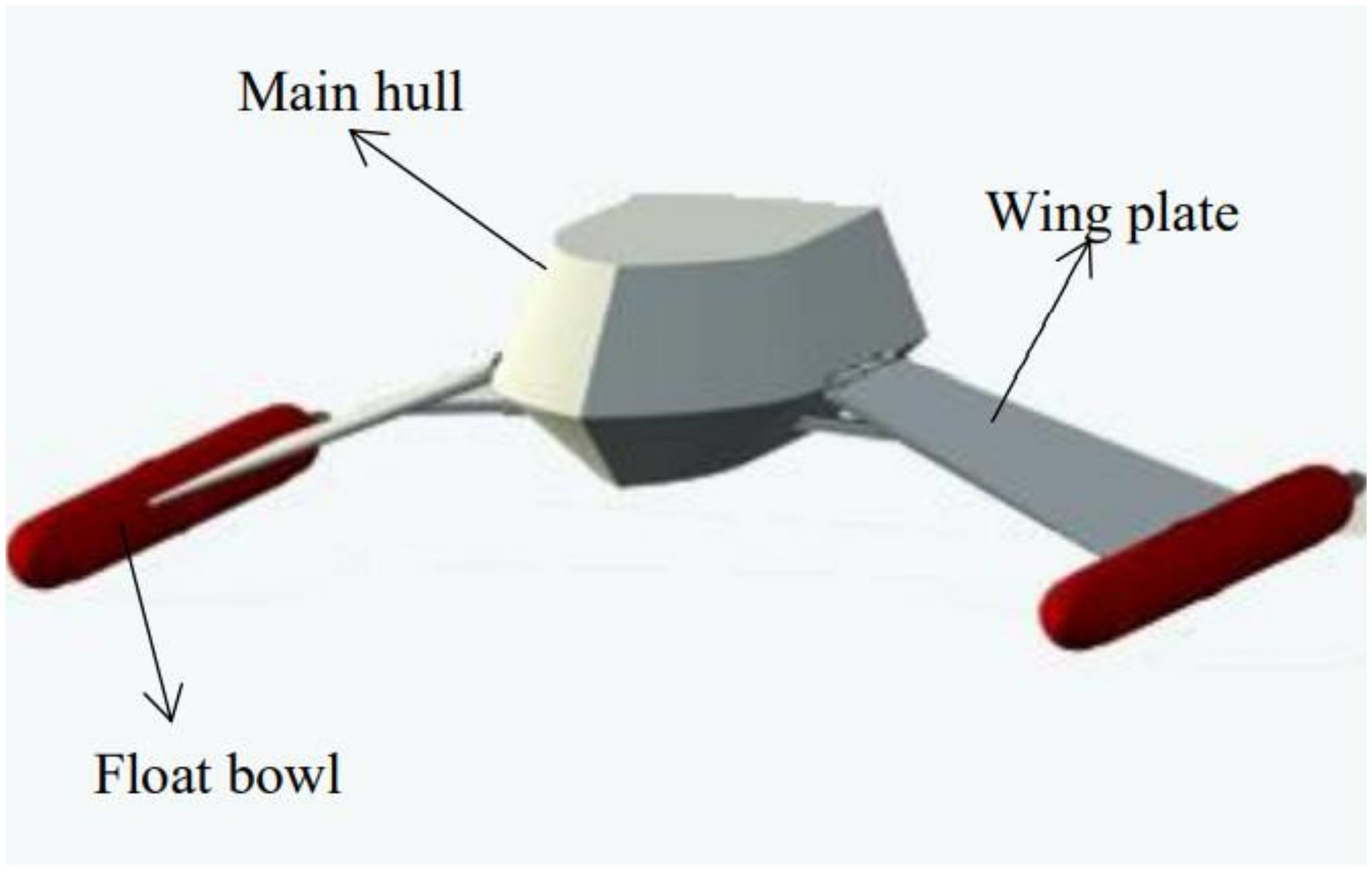
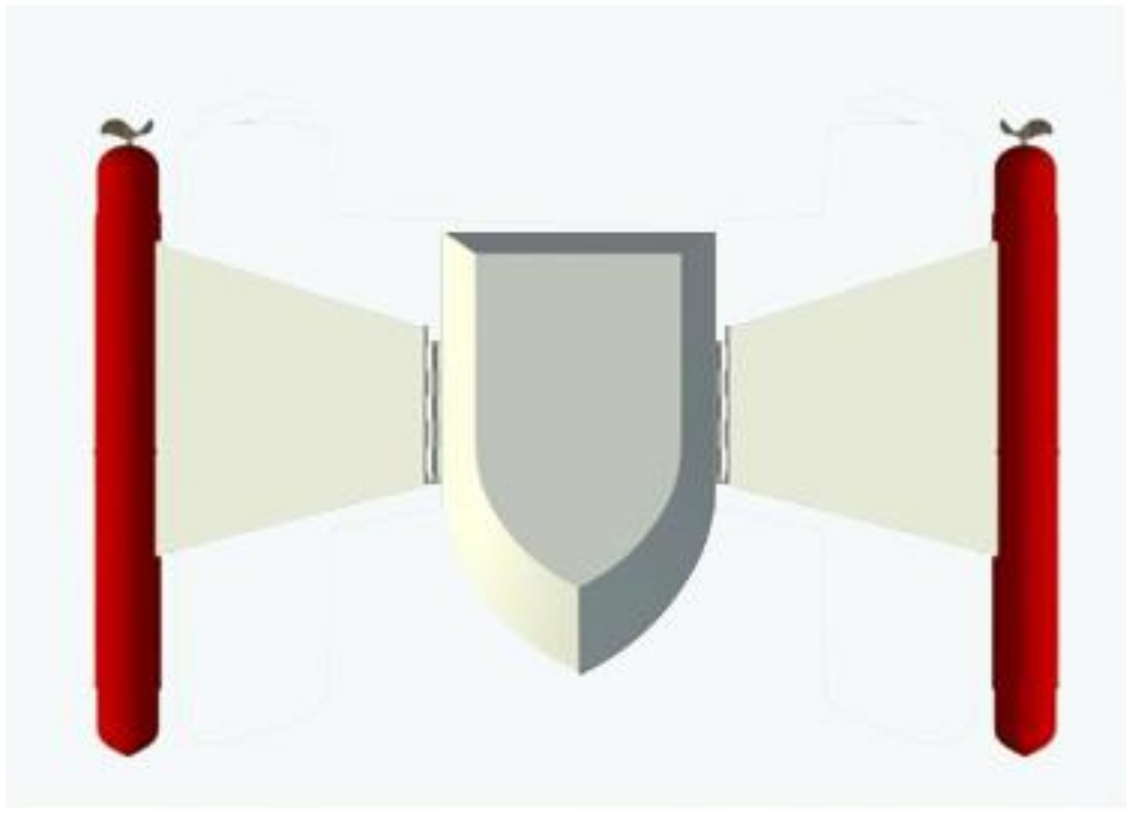
The Transformer has a morphing function that allows you to switch between high-speed mode and morphing mode, combining speed and smoothness. In high-speed mode, the side panels are tucked in to avoid the waves, allowing for a significant increase in speed when sailing in deep water. In deformation mode, the side panels are unfolded and the main hull is close to the water surface, increasing the contact area with the water surface and reducing the speed, lowering the center of gravity to improve stability and reduce the radar reflection area on the water, thus achieving a certain degree of radar stealth.

2. Conceptual Designs

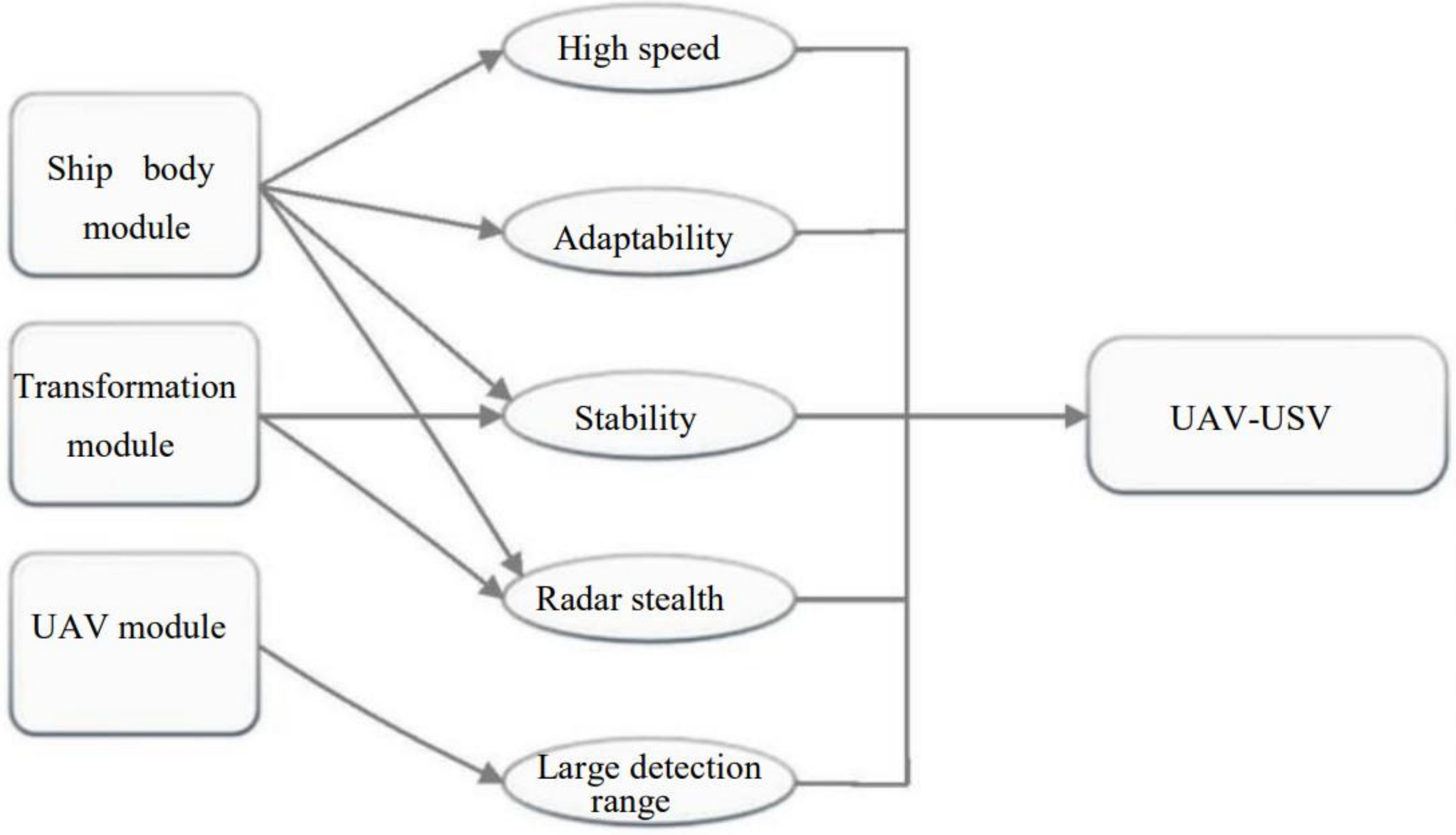
The objective is to design a multifunctional fast UAV-USV coupling system, as shown in Figure 1. Carrying UAV on board for the Transformer extends its reconnaissance range. A radar stealth material is applied to the surface of the hull after deformation to achieve some radar stealth. Two floats are added to the end of each wing to provide sufficient buoyancy to carry the relevant weaponry inside the floats.
In addition, in order to achieve high speed and stability, a catamaran structure with a deformed structure was used in the design. The hull and the connecting part of the ship were designed as a thin type to minimize the wave resistance. The main hull is designed above the water surface to reduce the contact area with the water, thus reducing frictional resistance. Furthermore, a pivot is provided at the link between the main body and the side wings, so that the side wings can be rotated around the pivot. By adjusting the angle of expansion of both wings, the stability of the ship at high speed is further ensured, and the deformation function enables the ship to sail close to the water surface, which increases the stealth effect with the radar stealth material.
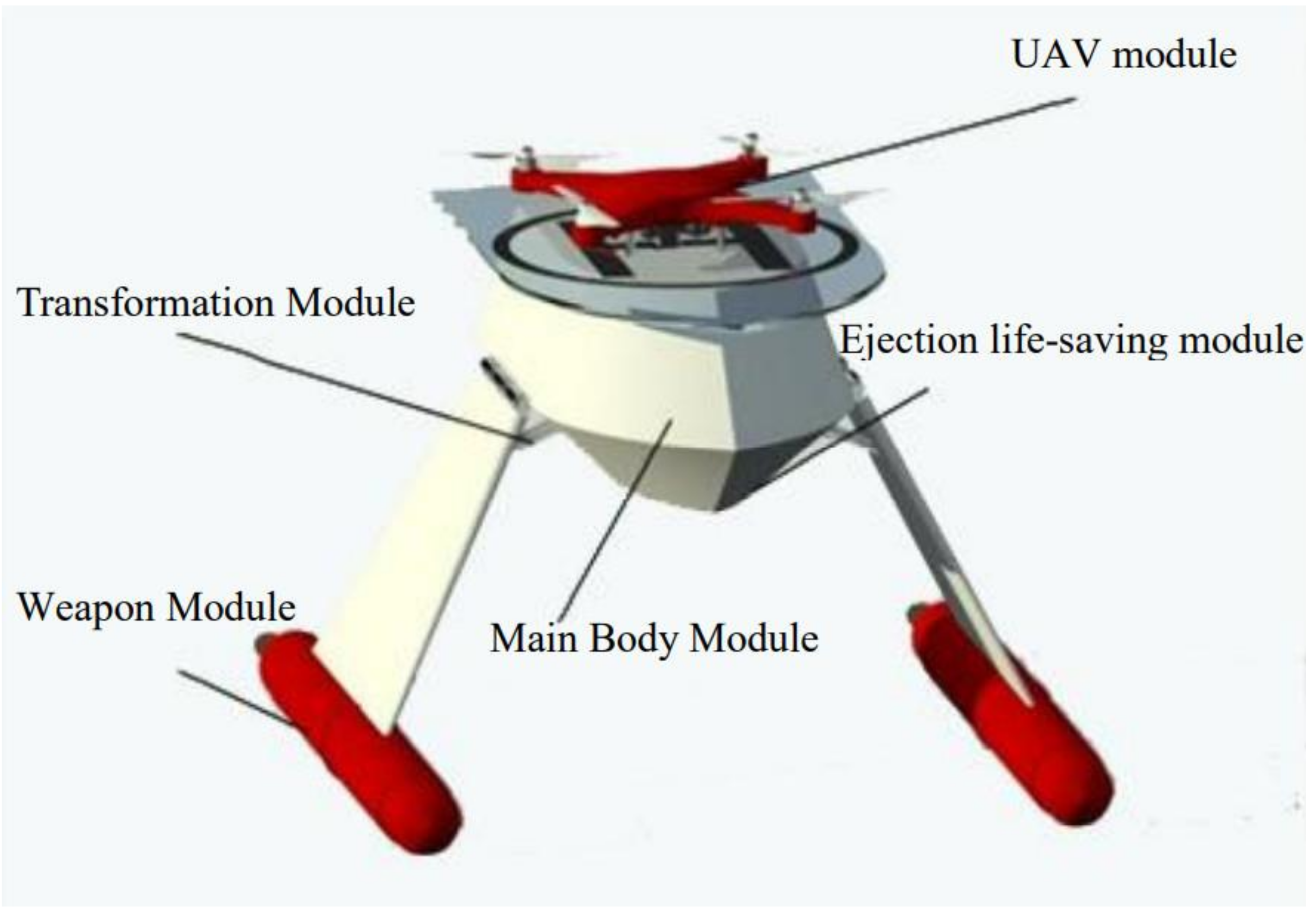
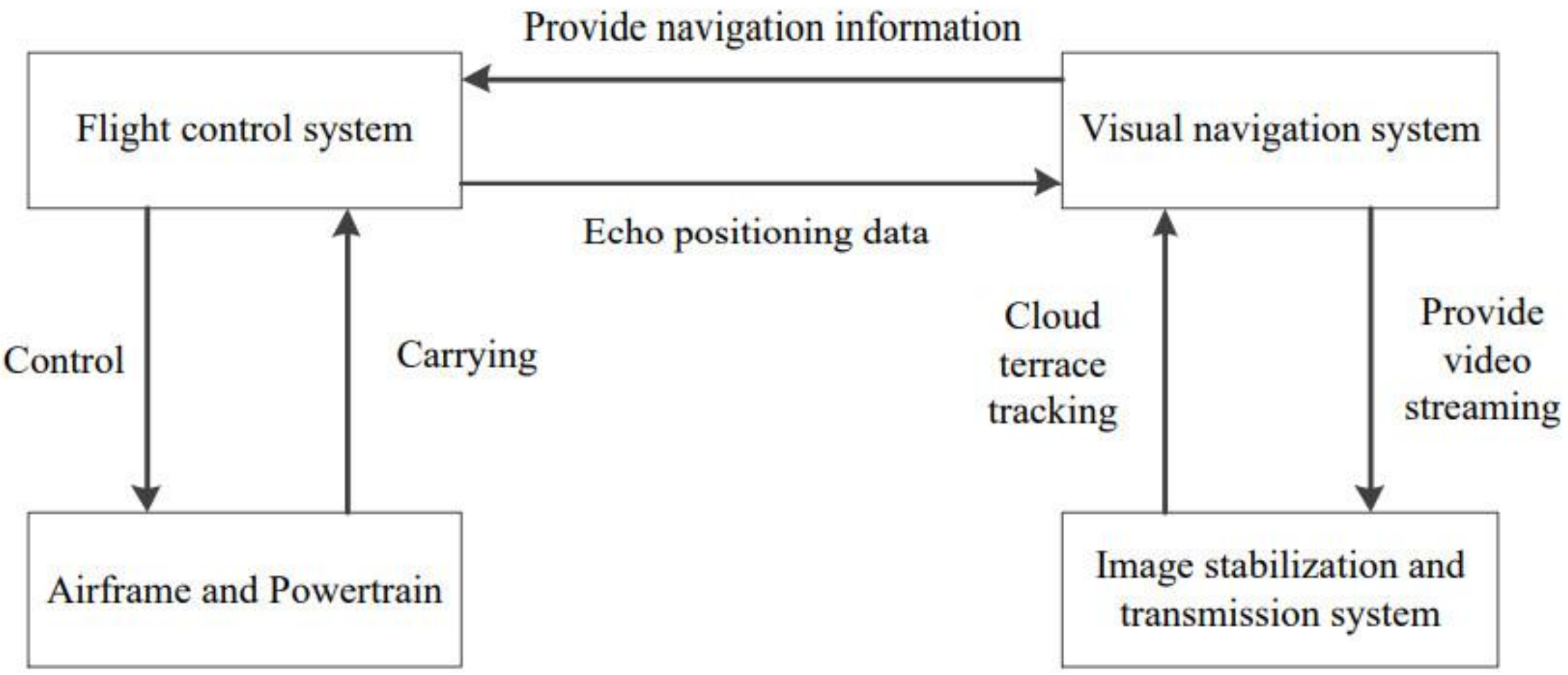
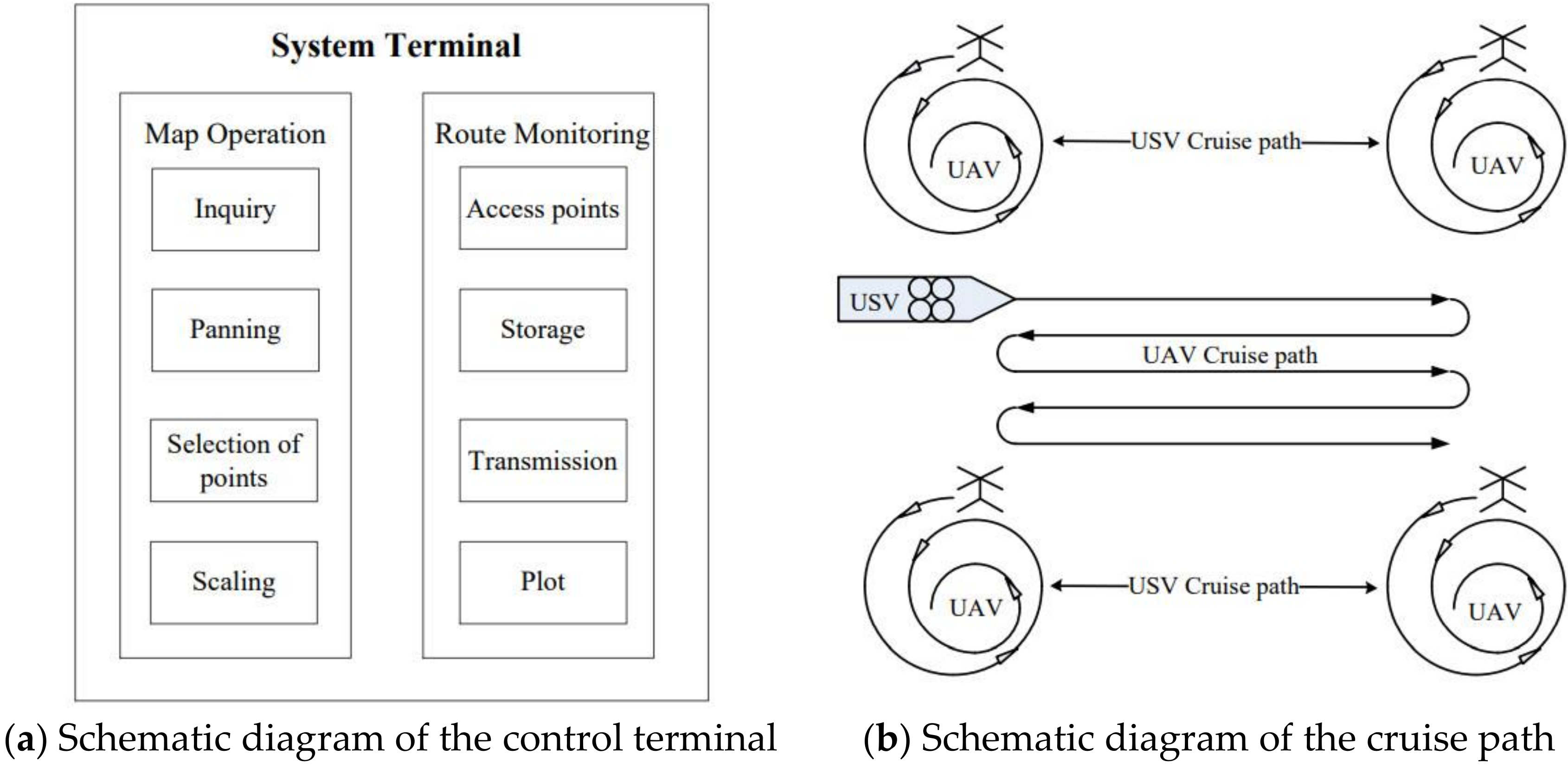
This system adopts a modular design, consisting of the ship body module, the deformation module, the drone module, the weapon module and the ejection rescue module, as shown in Figure 2. The main module of the ship includes the whole ship and the radar stealth material painted on the surface of the ship. The deformation module can control the deployment or retraction of both wings to ensure the radar stealth of the ship and the stability of the ship at high speed. The UAV module enables the system to have a larger cruising detection range and to reconnoiter places that are inaccessible or dangerous to the ship.
This system combines the ship body module, the deformation module, the UAV module, the weapon module and the ejection life-saving module together, so that the UAV has the characteristics of stability, speed, radar stealth and high load, which can be used for both military and civilian purposes. For military use, it can carry out military tasks such as enemy reconnaissance and target strikes with the appropriate equipment on board. For civilian use, it can quickly reach the scene in the event of a maritime accident to rescue people overboard, and can be used to explore some highly dangerous areas of the sea as well.

3. Design of the Modules

3.1. Ship Body Module Design

3.1.1. Selection of Vessel Type

With the continuous development of the marine industry, a variety of new high-speed hulls such as hydrofoils and catamarans have flooded into our view. The cross-sectional shape of the general high-speed catamaran hull is usually round bilge-shaped or pointed conical, and the shape of the stern end usually square-tailed or semi-square-tailed. The degree of contraction of the squaretail depends on the design speed of the boat; the higher the speed, the greater the degree of contraction it should be.
The many advantages of high-speed catamarans are as follows:
(1) When sailing at high speed, the resistance is smaller. For a ship in high-speed sailing, wave-making resistance accounts for the main resistant component; the lean and long catamaran’s piece can effectively reduce the wave-making resistance and shape resistance, making the performance of the catamaran better than the monohull at this time.
(2) Better initial stability. As the catamaran has two pieces separated by a certain distance, the transverse moment of inertia at the waterline surface is greatly increased, so the recovery moment is large and the initial stability is better.
(3) Better maneuverability. The two sheets are equipped with separate thrusters, and the steering of the vessel can be controlled by adjusting the speed of the two motors. Secondly, the spacing between the sheets makes a certain distance between the two thruster axes, which gives the catamaran better slewing.
By understanding the drawbacks of existing vessels and the advantages of catamarans, a high-speed three-dimensional rescue SUV was designed and built, as shown in Figure 3.

3.1.2. Design of the Ship’s Connecting Airfoil

The upper edge of the trapezoidal joint plate is connected to the main hull, the joint part can be rotated and the lower edge is connected to fix the two pieces separately. The advantages of this design are as follows:
(1) The pressure of the water is proportional to the depth of the water, so the lower part is subjected to a greater force, while the ship is mainly subjected to forces on the two pieces when travelling. The narrow top and wide bottom of the connecting plate are conducive to increasing the contact area between the connecting plate and the sheet, thus increasing the structural strength of the connecting position and enhancing the stability of the ship.
(2) The lower edge part is fixed. On the one hand, it can make the connection part more stable and can withstand greater impact. On the other hand, it can simplify the hull design, while also reducing the inconsistent deformation of the two sides of the hull due to the uneven stress on the connecting parts of the two sides of the hull.
The side view of the rotating connection plate is shown in Figure 4.

3.1.3. Design of the Float

When designing the float, it was considered that when Transformer is underway, the float is always located below the water surface and a large part of the resistance to the ship’s navigation comes from the resistance of the float moving through the water. Considering the special shape of torpedoes with low resistance, low noise and high maneuverability, we refer to the design of torpedoes in the design of the floats, as shown in Figure 5.

3.1.4. Selection of Hull Materials

There are several points to consider when modeling a ship.
(1) Changes in the material when exposed to water. Wooden materials are not suitable due to anisotropy, where there are differences in the dry shrinkage and wet expansion of the wood in all directions, and these may lead to defects such as cracking and warping.
(2) Density and strength of materials. Excessively dense materials will seriously affect the buoyancy of the ship, while materials that are not strong enough will not ensure the rigidity of the ship and the structural strength of the hull will be affected.
(3) The difficulty of processing the material. There are many types of materials, but the processing methods are different and the equipment required for processing is also different. Metal materials have excellent plasticity and many of the properties of the new alloys are very good, but the processing is difficult.
Based on overall consideration, it was decided that graphite, boron and silicon carbide fiber-reinforced composite materials would be used as the main materials of the hull, and wave-absorbing coating and conductive coating on the outer surface of the hull would be used to eliminate the discontinuity points and components between materials with different electromagnetic properties.

3.1.5. Radar Stealth Design

The nature of radar stealth is such that enemy radar cannot accurately detect the target’s echo signal. The radar scattering cross-sectional area (RCS) of a target characterises the amplitude of the target’s return signal to the radar. Therefore, to achieve radar stealth, the core aim is to reduce the target RCS [14]. Reducing the target RCS essentially means reducing the target’s return power or scattered-wave electric field strength, which is usually achieved by adopting a special shape design, or choosing wave-absorbing or wave-transparent hull fabrication materials, etc. In order to improve the radar stealth of the Transformer, it is planned that radar stealth coatings would be sprayed on the surface of the hull. Magnetic lossy coatings mainly consist of magnetic fillers such as ferrite dispersed in a dielectric polymer, and such coatings have good absorption in the low frequency band. The ferrite series of coatings from the U.S. Condictron company are 1 mm thick, and offer 2~10 GHz attenuation up to 10~12 dB, while being heat-resistant up to 500℃. Alternatively, Emerson’s Eccosorb Coating 268 E has a thickness of 1.27 mm, a weight of 4.9 kh/m3, and in the common radar band (1 ~ 16 GHz) has good attenuation performance (10 dB). The actual weight of the magnetic loss coating is usually 8~16 kg/m2; combined with the above and considering the low price of ferrite absorbing coatings, the strong absorption capacity and wide application characteristics, it was decided that magnetic loss coating should be sprayed on the hull to achieve the purpose of radar stealth.
In this paper, the frontal projection area of the USV is about 0.1148 m2, and the side projection area is about 0.252 m2. When the side wings of the USV are unfolded, it can be sailed close to the sea surface, and the reflective area of the surface layer is 0.4032 m2, which has a good stealth performance. Due to the small reflective area of the boat and the magnetic loss radar stealth coating on the surface of the hull, the radar stealth of the USV is achieved to a certain extent.

3.1.6. Transformer Power Control Design

The power control part of the Transformer is controlled by the model remote control and microcontroller together, and the control mode can be switched by remote control. In automatic mode, the UAV is controlled by the microcontroller; the operator sets the route on the PC and the UAV cruises along it. The operator can always observe the information from the camera installed on the UAV through the display side of the UAV image transmission system, and judge whether to switch to manual mode accordingly. In the manual mode, the operator can use the remote control to control the navigation, deformation and rescue functions.
The system block diagram for the power control section is shown in Figure 6.

3.2. Design of the Deformation Module

The control structure of the deformation module is shown in Figure 7. The deformation module mainly consists of a rotating shaft linking the side wings to the main body of the UAV, a hydraulic lever and the associated control circuit. The UAV is equipped with mechanical devices such as motors and hydraulic rods on both sides of the connecting plate, and circuits such as the main control module, the wireless receiving module and the motor driving module inside the UAV. When the wireless receiving module of the UAV receives the unfolding (stowing) command from the host computer (computer), it is immediately transmitted to the UAV main control module via the SPI bus. The main control module outputs PWM signals to control the motor drive based on the L298N driver chip according to the received command, so that the motor drives the hydraulic rod and completes the corresponding action correctly. In addition, when the connecting plate expands (retracts) and reaches the limit angle, the mechanical device will automatically stop extending (contracting), which plays a protective role for the overall structure of the UAV.
The UAV deformation module allows the UAV to be in a standing position and a prone position, as shown in Figure 8.
When the Transformer is cruising normally, it is in a standing position, and the boat can sail faster because of reducing the contact area with the water and reducing frictional resistance (sailing resistance).
When the Transformer is moored or sailing in high wind and waves, it can be in a prone state, with the main hull close to the water surface, causing the overall center of gravity of the ship to drop, enhancing the wind and wave resistance and improving the concealment of the ship.

3.3. UAV Module Design

The UAV module is the aerial cruise component of the multifunctional fast UAV-USV coupling system, and provides the system with a very wide field of view, improving the system’s detection and cruise capability to a certain extent. At the same time, the wireless charging of the UAV greatly improves the range of the UAV and the robustness of the system.

3.3.1. Wireless Charging Structure Design

The Transformer is controlled by the operator on the land and there is no operator on the Transformer. Therefore, contact-based charging cannot be used on the Transformer. Instead, wireless charging is applied to provide the energy for the UAV and bring more convenience. In the wireless charging structure, the coil is the core component of resonantly coupled electric energy wireless transmission technology. Reasonable design of coil parameters, finding the optimal number of turns and average radius, can offer the full advantages of this technology. Optimizing the coil parameters is of great significance to achieve high power and high efficiency transmission of the system. Commonly used coil construction types are planar spiral and cylindrical spiral tube types. The planar spiral coil has a higher coupling coefficient and quality factor, which makes it more suitable for radio energy transmission, and it is more convenient to place the planar spiral coil under the chassis.
Where Dmax and Dmin are the maximum and minimum outer diameter of the coil, respectively, S is the coil turn spacing, W is the wire diameter, and N is the number of turns of the coil. According to the geometric relationship between the parameters of the coils in Figure 9, it can be deduced that:
r a v g = 0.5 D max + D min
β = D max D min D max + D min
D max = N 1 × S + N × W + D min
Here: ravg is the average radius of the coil, and β is the coil fill rate.

3.3.2. Design of the UAV Control Search Principle

Based on this system, the UAV can follow the route planned by the operator on the computer control software to carry out cruise monitoring work, and it can be controlled by the software to reach any point in the cruise range. The navigation technology is the key technology to realize the UAV’s autonomous cruise, which is divided into a combined navigation system and a search control system.
Adopting a combined navigation system can improve the accuracy and stability of navigation. In an inertial navigation system that assists the primary navigation system, the signal quantities outputs by one or more auxiliary systems are compared with similar signal quantities outputs by the primary system, and the signal quantities of the primary system are corrected according to the differences. This can obtain higher navigation accuracy than using the inertial navigation system independently, so this system adopts the scheme of simultaneous positioning of BeiDou and INS to get accurate navigation information.
The role of the search control system is to plan the cruise point, and the UAV relies on the combined navigation system to accurately reach the cruise point for operation. As shown in Figure 10, the operator sends the navigation information through the control terminal to the UAV master control via the RF communication module. The UAV master control compares the real-time position information with the navigation information, and adjusts the flight parameters according to the position difference to ensure that the UAV arrives at the waypoint accurately and completes the cruising task. During the cruise, the image stabilization and transmission system provides a stable image by controlling the camera gimbal, and transmits the video stream by controlling the RF communication system so that the operator can obtain a stable image at the control terminal.
The schematic diagram of the control terminal is shown in Figure 11a, and the positioning data returned by the UAV combined navigation system describes the UAV flight route. After taking and storing points, they are transmitted to the system terminal for route plotting, which can monitor the trajectory of UAV flight. The trajectory of the UAV flight is plotted on the electronic chart, and the route display can be completed. The system terminal program needs to operate on multiple threads, and in order to ensure the safety of the program, the thread where the computer drawing is located and the UAV serial communication thread cannot make direct data calls. Therefore, we adopt the way of calling the program module interface to read the UAV route information to the electronic chart, and then carry out the corresponding map operation. The route information is stored using the chain table technique and the cruise path is plotted using the GDI+ technique [15,16,17]. The cruise path schematic is shown in Figure 11b.
The UAV is equipped with a camera gimbal, positioning module and power monitoring module to collect information on the target, its own position, its own power, and transmit the signal to the control terminal over long distances via the RF communication module. The computer receives and runs the remote monitoring software based on Qt design to process and analyze the data returned by the sensors on the control terminal, as shown in Figure 12. Afterwards, the terminal operator issues the relevant instructions for controlling the operation of the UAV, realizing the long-distance control and management of the system and the two-way transmission of information, so that the cruise, landing and search and rescue functions of the UAV can be integrated and controlled.

3.3.3. UAV Landing Process Design

Based on the actual water conditions and the functional conditions of the existing UAV, a set of UAV-guided landing procedures are designed so that the UAV can accurately land on the charging platform on top of the USV. This is done in the following way: through the self-developed platform control software, the shore-based terminal controls the UAV to approach the landing position on the Transformer mounted platform, the UAV is calibrated according to the camera to land accurately, the varistor senses the weight of the UAV and the wireless charging system is activated to charge the UAV.
The operational procedures for landing and charging the drone can be briefly described as follows.
(1) After releasing the UAV from the high-speed three-dimensional rescue drone boat, the shore-based terminal determines whether the UAV needs to be recharged to ensure normal operation during the work of cruising and monitoring in the corresponding sea area.
(2) The operator analyses the information about the Transformer displayed by the terminal (including location information, environmental information), controls the Transformer and selects safe waters for docking, and cooperates with the landing of the unmanned aircraft.
(3) Through the Beidou navigation system, the shore-based terminal instructs the UAV to approach the position marked on the electronic chart of the selected navigational marker.
(4) Due to the uncertainty of the UAV’s position at sea and the error of the positioning system, we used a combination of the UAV initiating the landing guidance procedure and shore-based control to enable the UAV to land accurately on the wireless charging panel on the beacon.
(5) After the drone lands, the varistor senses the weight of the drone, and the wireless charging system is activated to charge the drone.

3.3.4. UAV Coupled System Mapping Design

In order to enable USV operators to keep track of the surrounding waters, research is needed on the system’s moving graphical transmission, which can enable real-time monitoring of itself and its surroundings.
The camera sends the captured video signal to the video signal transmitter, such as the operation of the Transformer itself, the water condition, the information of people falling into the water and other video information. The video signal transmitter transmits to the distant video signal receiver through the antenna, and the received analog signal is sampled, quantized, and coded into a digital signal through the video capture card, which makes the monitor at the monitoring end able to correctly display the video signal captured by the camera. The structure diagram of the system is shown in Figure 13.
In this system, the TS832 transmitter and RC832 receiver are used for the wireless image transmission module, which can transmit analogue video signals over a distance of 3 km in an open environment. The corresponding transmitting and receiving frequencies can be selected by adjusting the FM button on the receiver. The frequencies are displayed by LED digital tubes, and up to 40 frequencies are available for selection, providing better interference immunity. The physical object is shown in Figure 14. The physical display of the UAV module is shown in Figure 15.

3.4. Overall Circuit Design

3.4.1. Design of the Main Control Module

In order to realise the functions of precise docking and charging of UAV and automatic cruising of USV, the working principle of a microcontroller minimum system controlling peripheral circuits is used, and the STM32F4 series based on the Cortex-M4 core is chosen here. The STM32F407 is designed specifically for industrial control and wireless networks, with its rich on-chip peripherals and interfaces, and its high development efficiency and ease of program download and debugging.
The minimum system of a microcontroller is the circuit that can make the microcontroller work properly together with a minimum number of components. The minimum system of STM32F407 includes an STM32 microprocessor, clock circuit, reset circuit and power circuit. The schematic diagram of the STM32F407 minimum system circuit is shown in Figure 16.

3.4.2. Design of the RF Communication Module

The RF communication module is the core circuit part of the communication between the Transformers, the console and the UAV. The module ensures the transfer of information between the coupled units in the UAV coupling system, and it is an indispensable part of the communication between the units, mainly consisting of the transmitting part and the receiving part of the circuit.
The core part of the transmitter and receiver modules is the NRF24L01 chip. The NRF24L01 is a new monolithic RF transceiver device that works in the 2.4~2.5 GHz world common ISM band. The built-in frequency generator, power amplifier, crystal oscillator, modulator, demodulator, enhanced ShockBurst mode controller and other functional modules, its protocol settings, output power, and communication channels can be configured through the SPI interface. The NRF24L01 has extremely low power consumption and can operate at a voltage of 1.9 V to 3.6 V. The extremely low power consumption does not affect the sensitivity of the chip, and it can be used in open areas up to 1000 m away.
The STM32 and the NRF24L01 use the Serial Peripheral Interface (SPI) communication. The SPI communication mode diagram is shown in Figure 17. The host and slave write the SPI-based NRF24L01 driver, the host receives the matrix keyboard input and controls the NRF24L01 to send data; after the slave receives the information, the NRF24L01 communicates with the microcontroller to obtain the received data, which is more convenient to use.
A typical NRF24L01 (single-ended50Ω RF) application design is shown in Figure 18. The microcontroller operates it through six control and data pins, changing the NRF24L01’s CONFIG register to determine whether it operates in the transmit state, receive state, or sleep state to enable proper communication between the entire system.

3.4.3. System Power Module Circuit Design

The STM32FF407 microprocessor needs to provide a rated operating voltage of 3.3 V, and the RF communication module and motor drive module both require a voltage of 3.3 V; accordingly, this system uses the common 3.3 V voltage input design, and provides 3.3 V for each module by using a low dropout linear voltage regulator chip, model AMS1117, from AMS Power Management IC Design. The on-chip trimming of the AMS1117 allows the reference voltage to be adjusted to within 1.5% error, and the current limit is adjusted to reduce the stress caused by overloading the regulator and power supply circuitry, making the circuit voltage more stable. Its circuit design diagram is shown in Figure 19.

3.4.4. UAV Charging Method Design

There are currently two main types of drone charging methods: wired charging and wireless charging. Compared to traditional wired charging, wireless charging technology eliminates the need for tedious charging operations and increases the safety and reliability of the charging system. It can also be adapted to a wide range of harsh environments and weather. There are three main types of wireless charging technology applicable.
From Table 1, it can be concluded that the magnetically coupled resonant wireless charging technology has the following essential differences compared with other wireless charging technologies:
(1) Compared with the electromagnetic induction wireless transmission technology using the electromagnetic induction principle, the transmission distance is greatly improved, breaking the limit of the wireless transmission distance of the electromagnetic induction principle only within 1 cm, and the theory shows that if the influence of other objects in space is not considered, the transmission distance will reduce.
(2) Compared with the radio wave type wireless transmission technology using the microwave principle, it has the feature of high transmission power. There is an increase in the order of magnitude of microwave power wireless transmission from a few milliwatts to 100 milliwatts, to tens of hundreds of watts, and the former is much higher than the latter in terms of charging efficiency.
Based on overall consideration, the magnetically coupled resonant wireless energy transmission technology with longer transmission distance, better transmission efficiency, higher charging efficiency and better lateral offset adaptability was adopted. Magnetically coupled resonant wireless charging circuits are based on the theory of electromagnetic resonance and consist of a resonant coil with the same resonant frequency combined with the transmitter and receiver. The UAV wireless charging transmitter and receiver module circuits are shown in Figure 20 and Figure 21.
A schematic diagram of the overall circuit module assembly inside the Transformer is shown in Figure 22. Assembling all the modules described above, a physical display of the shape-shifter is shown in Figure 23.

4. Performance Analysis

4.1. Boat Resistance Analysis

VOF is a numerical technique historically used to track and localize the free surface flow of only one fluid, and now is often used for multiphase fluid flows. It belongs to the class of Eulerian methods characterized by the fact that the grid is stationary or moves in some prescribed way to accommodate the evolving shape of the interface. In the VOF method, the marker function is represented by a fraction of the computational grid cells occupied by the fluid assumed to be the reference phase [18,19]. Currently, computational fluid dynamics (CFD) is widely used. In numerical simulations using computational fluid dynamics methods, it is necessary to discretize (generate meshes) the computational region using effective mesh discretization methods. The speed and quality of mesh generation largely determine the time consumption, accuracy and stability of the computation. According to the relevant research statistics, the time of mesh generation accounts for about 60% of the total computational time when using CFD to solute the fluid problems [20].
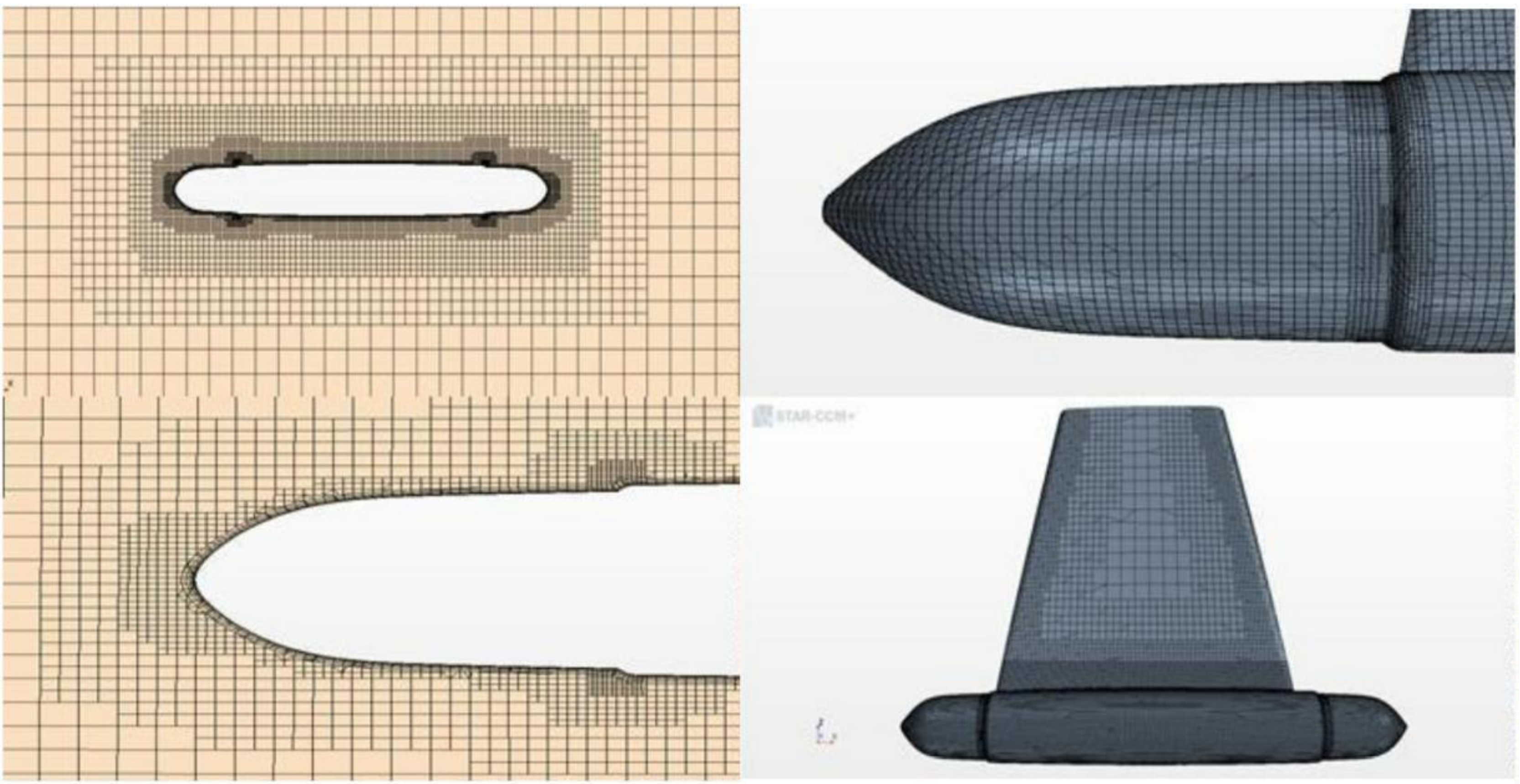
The overall structural model of the Transformer is first made using Solidworks, and then imported into the continuum media mechanics numerical software STAR-CCM+. The CFD model is established by imposing the corresponding wave flow conditions, and the VOF method is used to solve and analyze the CFD problem with free liquid surface, and then test the stability of the Transformer structure, and the computational accuracy is divided as shown in Figure 24.
The total resistance of a ship during navigation is divided into the above-water part resistance and the underwater part resistance. The above-water resistance is air resistance, while the underwater resistance is friction resistance, wave-making resistance and viscous pressure resistance.
The current practice of calculating the resistance of a ship is to divide the total resistance Rt into three parts: frictional resistance Rf, viscous pressure resistance Rpv and wave-making resistance Rw. That is, Rt = Rf + Rpv+ Rw, where Rf is calculated using a fairly flat plate, and Rpv and Rw are the residual resistance, which is converted using a similar comparison rate. For low speed boats, frictional resistance accounts for about 70% to 80% of the total resistance, viscous pressure resistance accounts for more than 10%, and wave resistance is very small. However, as for the Transformer, the velocity is high and the wave resistance will increase sharply, reaching 40% to 50% of the total resistance. Therefore, reducing the frictional resistance and wave resistance can greatly improve the ship speed.
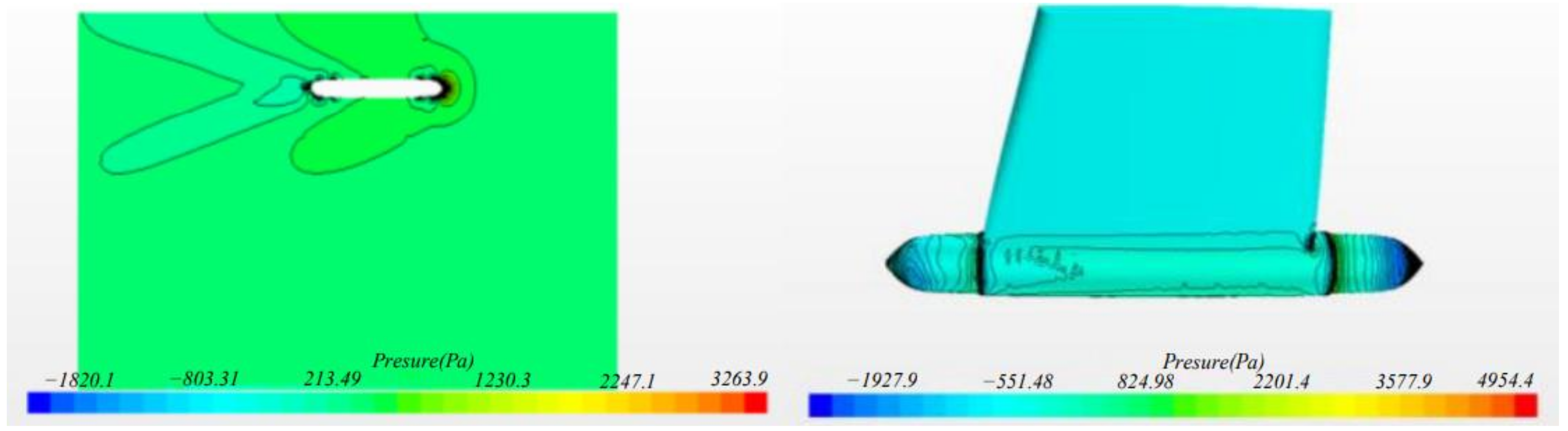
The distribution of wave-making resistance is related to the position of the ship, which is different from the frictional resistance. The wave-making resistance is sensitive to the ship’s shape line, and the change of the ship’s shape line can obviously reduce the wave-making resistance. Through simulation calculation, the dynamic wave resistance distribution of this unmanned vehicle can be obtained. As shown in Figure 25, two maximum pressure zones are formed near the two stagnation points of the hull head and tail, and their wave-generating effect is the strongest; the closer it gets to the ship, the less obvious it is.
The distribution of wave resistance is related to the position of the hull. Different from the frictional resistance, the wave resistance is sensitive to the shape line of the ship, and the proper change of the shape line can obviously reduce the wave resistance. The distribution of the wave resistance when the Transformer is moving is shown in Figure 25, where, the total number of elements is 136524. Two maximum pressure zones are formed near the two stagnation points of the hull head and tail. On maximum pressure zones, wave-generating effect is the strongest, and the effect on the place near the middle position of the hull will be not obvious. Where velocity of the unmanned surface vehicle relative to water is 0.9 m/s, Froude’s number is 0.259.
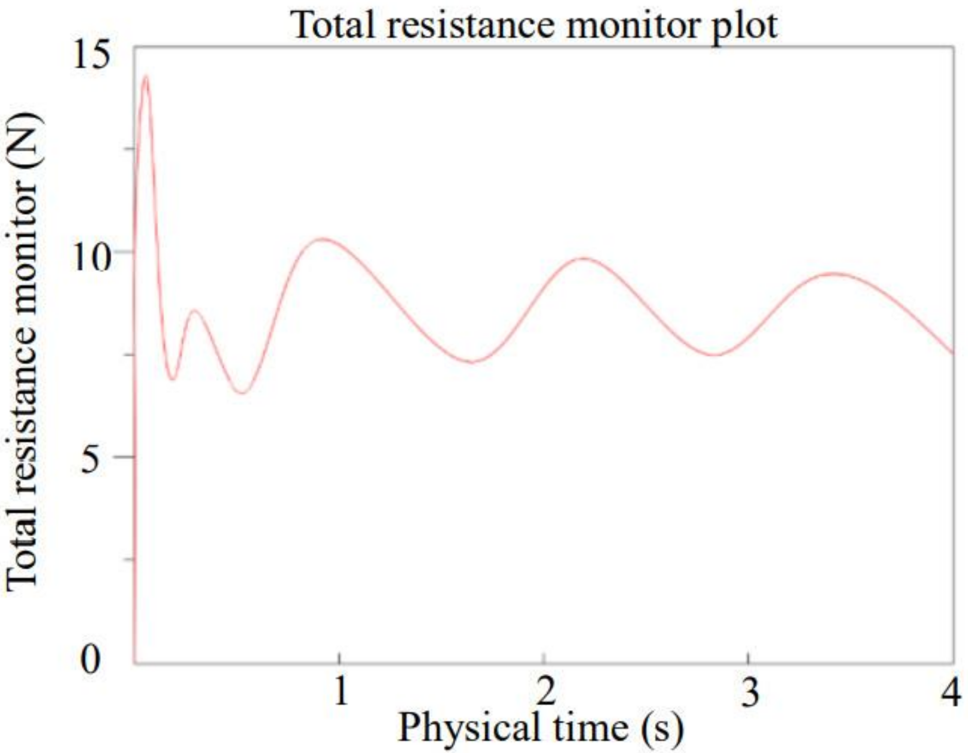
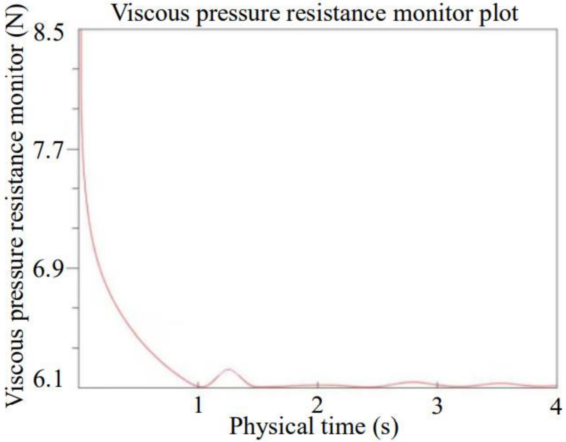
The results of the total resistance and viscous pressure resistance analysis are shown in Figure 26 and Figure 27, respectively. The simulation calculation shows that the total resistance of the ship is about 13.4492 N and the viscous pressure resistance is about 6.1870 N, which shows that the wave resistance accounts for about 46% of the total resistance in this ship.

4.2. Wireless Charging Analysis

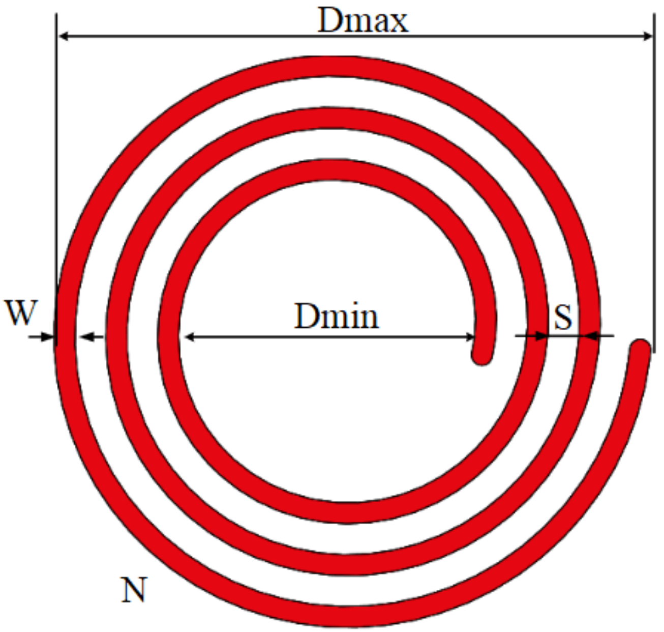
The coil charging efficiency is related to the coil parameters, the voltage and current parameters of the buck regulator module, and the distance between the coils. The coil parameters include the outer diameter, inner diameter and number of turns of the coil. To facilitate the design, we only optimize the number of turns of the coil and test the designed charging coil to determine the optimum charging distance.

4.2.1. Theoretical Models

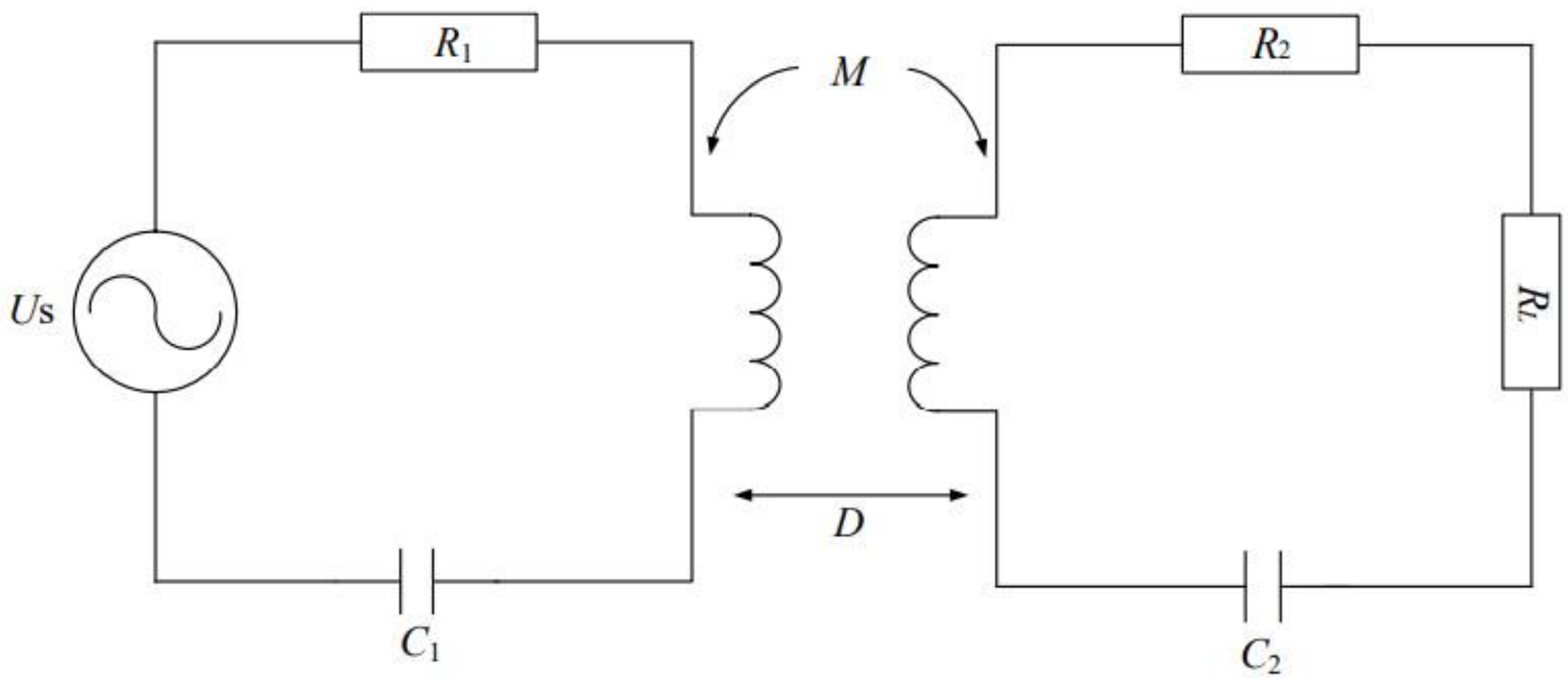
The magnetically coupled resonant wireless charging system mainly consists of four parts: the high frequency power supply, the transmitting coil, the receiving coil and the load (the UAV battery). A magnetically coupled resonant circuit model is shown in Figure 28.
Where US is the power supply, RL is the equivalent load converted to the receiving coil side by inductive coupling, C1 and C2 are the capacitance, which represents the coil distance, and M is the mutual inductance between the coils. The charging efficiency of magnetically coupled resonant wireless charging systems is:
η = ( ω M ) 2 R L ( R 2 + R L ) [ R 1 ( R 2 + R L ) + ( ω M ) 2 ]
M = μ 0 π N 1 N 2 r 1 a v g 2 r 2 a v g 2 2 ( D 2 + r 1 a v g 2 ) 1.5
where η is the transmission efficiency, ω is the transmission system angular frequency, N1 and N2 are the number of turns of the transmitting (receiving) coil, and r1avg and r2avg are the average radius of the transmitting (receiving) coil.

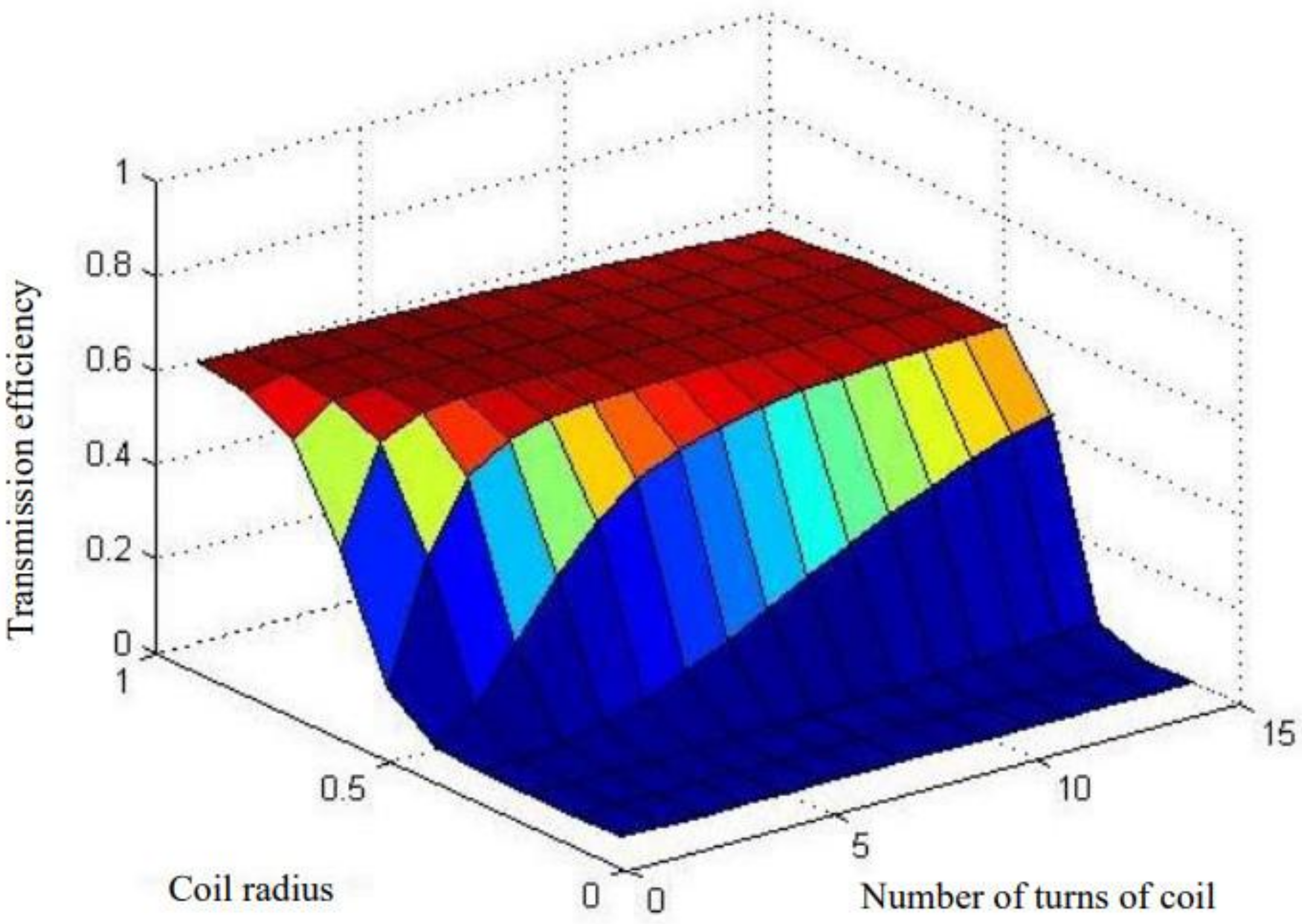
4.2.2. Optimization of the Number of Turns in the Coil

Under the conditions of f = 0.5 MHz, US = 36 V, D = 0.02 m, selection of copper wire as material, coil winding guide wire diameter according to the maximum current value that the wire can withstand is taken as 1 mm. The platform range is 1 m long and 1 m wide. Taken ravg = 0.1~1 m, N = 1~15. Based on the above equations and through Matlab simulation, Figure 29 and Table 2 can be obtained.
From Table 2 and Figure 29, it can be seen that the maximum transmission efficiency is achieved when the number of turns of the coil is 8 or 9. Considering that increasing the number of turns will reduce the transmission power, the number of turns of the coil is taken to be 8, and the simulation transmission efficiency is 58.5% at this time.

4.2.3. Determination of the Charging Distance

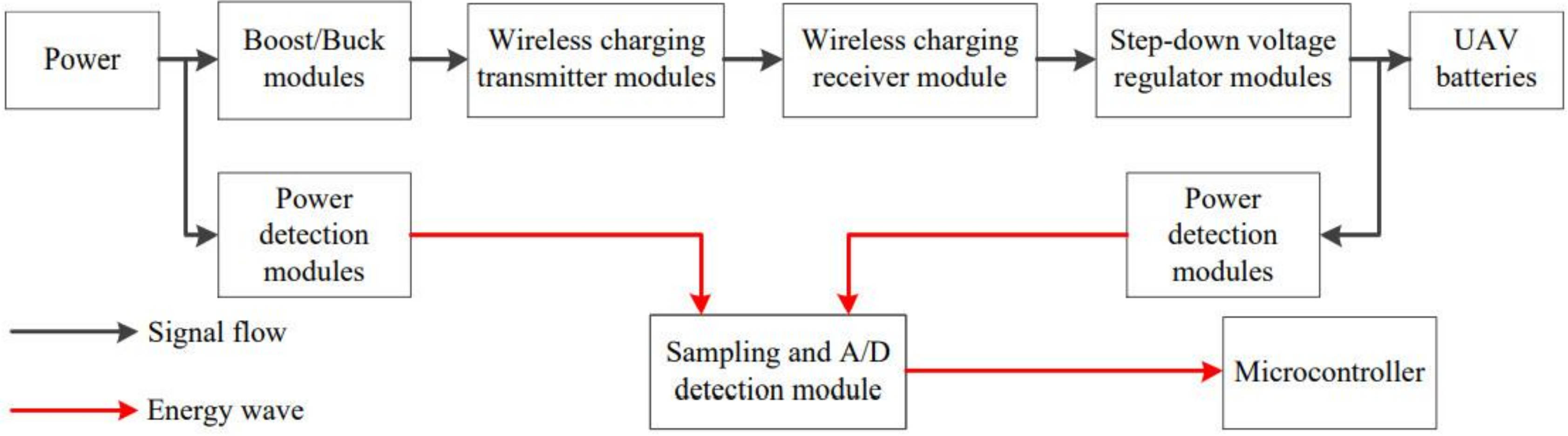
The power detection circuit is designed to test the charging power of the UAV. It can calculate the charging efficiency of the UAV under actual conditions, and test the charging efficiency of the UAV at different inter-coil distances, and then determine the optimal charging distance. The specific process of the experimental test is shown in Figure 30.
MAX4211 is a dedicated power detection chip. A sampling resistor of small resistance value is connected in series between the power supply and the load, and the inflow current is found by taking the voltage difference between the two ends of the sampling resistor. After collecting the input DC voltage, the product of the two is the input power. After deriving the input power output and power proportional to the signal, the signal can be sent by the microcontroller detection.
The power detection module equipped with MAX4211 is connected to the power output and the battery input of the UAV, respectively, so that the real-time power of the power output and the UAV charging can be measured. The power signal output from MAX4211 is transmitted to the high-precision 16-bit AD converter chip ADS1118 for power sampling and AD conversion, converted to Single Chip to receive and store the converted power signal, and sent to the host computer through the serial port. The host computer fits the power curve to the sampled power points through the software, and the UAV battery input power is divided by the power supply output power to get the UAV charging efficiency.
By varying the distance between the coils, the charging efficiency at different distances is derived as shown in Figure 31.
As can be seen from the diagram, the charging efficiency is highest when the distance between the coils is 4 cm. Therefore, we fixed the receiving coil at a position of 4 cm from the bottom of the drone.
According to wireless charging analysis, the receiving coil cloud should be fixed at a position of 4 cm from the bottom of the drone to improve the charging efficiency and insure the operation of UAV.

4.3. Ship Load-Bearing and Stability Analysis

4.3.1. Calculation of the Center of Gravity and Floating Center

In order to ensure the stable operation of the surface rescue drone, a certain height of stability of the center of gravity should be maintained. To this end, the center of gravity and the floating center of the surface rescue drone should be located separately according to the general arrangement, i.e., the center of gravity and the floating center of each part should be listed separately on the general arrangement diagram. The mass and center of gravity of the Transformer are shown in Table 3.
x g = Σ P i x i Σ P i
y g = Σ P i y i Σ P i
z g = Σ P i z i Σ P i
x b = 0 d x d V V = 0 d A w x f d z V
z b = 0 d z d V V = 0 d A w z d z V
y b = 0
Where, Pi is the weight of the heavy load on the Transformer, xi, yi and zi are the coordinates of the center of gravity of Pi, xg is the longitudinal coordinate of the center of gravity of the Transformer, yg is the lateral coordinate of the center of gravity of the Transformer, zg is the vertical coordinate of the center of gravity of the Transformer, AW is the waterline area, d is the corresponding draught, xb is the longitudinal coordinate of the center of gravity of the Transformer, yb is the lateral coordinate of the center of gravity of the Transformer, zb is the vertical coordinate of the center of gravity of the Transformer, and V is the volume of drainage.
From Equations (6)–(8), the position of the center of gravity for the Transformer is obtained: xg = 0.601, yg = 0, zg = 0.167.
From Equations (9)–(11), the floating center position of the Transformer is obtained: xb = 0.614, yb = 0, zb = 0.215. When the height of the floating center is higher than the gravity center, the Transformer can voyage stably.
The height of initial stability, i.e., the height of the stable center, can be expressed as: h = zb + r − zg = zm − zg = 0.013.
In this equation, r is the radius of the transverse stability center, zm is the height of the transverse stability center from the baseline.
r = I x f V = l A l F 2 3 y 3 d x V
Ixf is the area moment of inertia of the positive floating waterline WL area against the cross-tilt axis xf through the drift center F.
In order to maintain the balance of the Transformer during rescue, there should be:
x b = x g
y b = y g
If x b x g , y b y g , the general arrangement of the Transformer should be adjusted, although not absolutely equal, so that:
t g ϕ = x b x g z b z g
where ϕ is the longitudinal inclination angle of the range of 0°~15°, with the data obtained as ϕ = 0.27 ° .

4.3.2. Load-Bearing Analysis

Determining the mass and displacement volume of a surface rescue drone is one of the main tasks of design. When designing a surface rescue UAV, the aim is always to minimize the mass while achieving the main performance [21]. It is assumed that the masses and float volumes of the main components of the USV are as shown in Table 4.
Then total mass:
W = W u + W c + W 1 c + W e + W b
Total float volume:
r = I x f V = l A l F 2 3 y 3 d x V
Since the payload is all contained within the shell, Vu = 0, if the relative weight of each major component is expressed separately by γ i , then:
γ i = W i V i
In order to ensure the balance of the surface rescue drone in the water, the equation should satisfy W = γV, where γ i is the specific gravity of seawater, and
V = W γ = W u V u + W c V c + W 1 c V 1 c + W e V e + W b V b
From Equation (16) and Equation (19) the following can be obtained:
W 1 γ b γ = W u 1 γ b γ u + W c 1 γ b γ c + W i c 1 γ b γ i c + W e 1 γ b γ e
It can be seen from Equation (20), for the surface rescue Transformer with floating body material, when a certain group of relative specific gravity γ i is smaller than the relative specific gravity γ b of floating body material, 1 γ i γ b will become negative. At this time, increasing the mass of W i will not only increase the displacement of the Transformer, but will also make the displacement decrease.

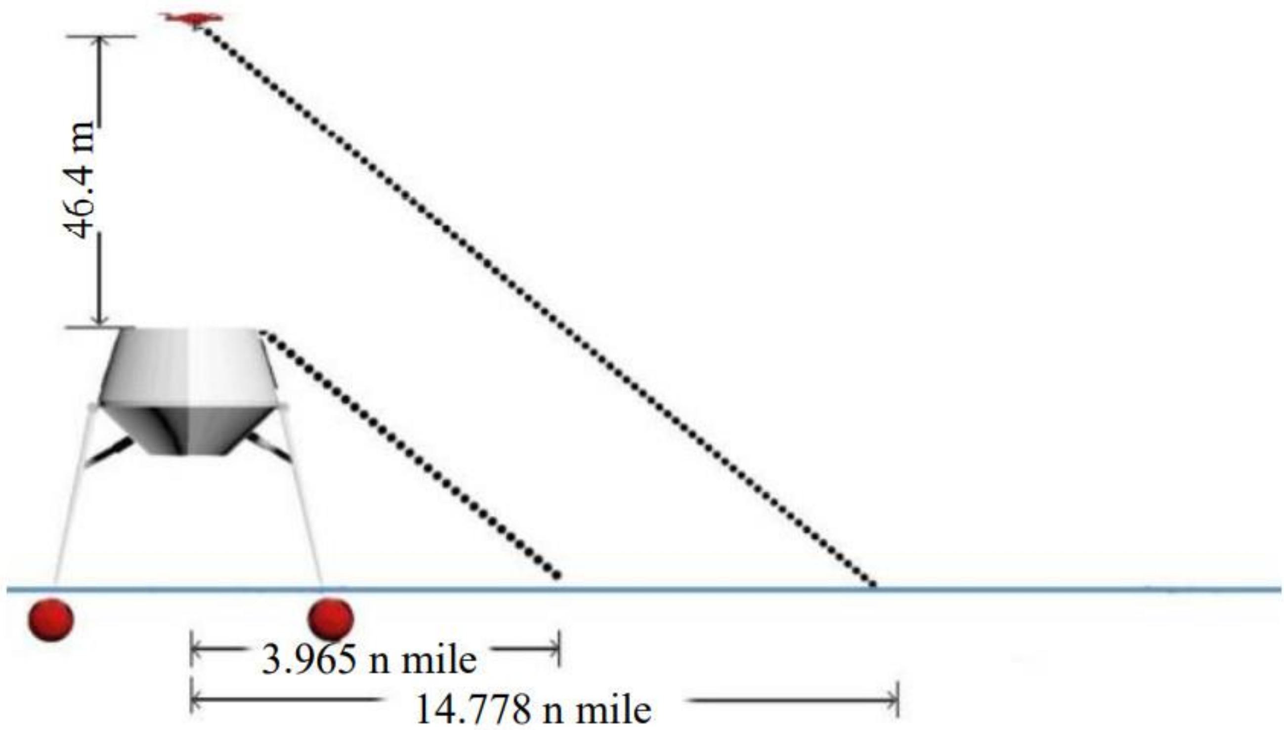
4.4. Detection Distance Analysis

In nautical science, when the eye height of the surveyor is zero, the theoretical maximum distance that the surveyor can see the object (geographical visibility distance) in good visibility is given by the following formula:
D 0 ( n   mile ) = 2.09 H ( m )
where H is the height of the vertex of the objective from sea level (m),
USV detection distance is: D 01 = 2.09 × 3.6 = 3.965 n   mile , and UAV detection distance is: D 02 = 2.09 × 50 = 14.778 n   mile , the USV carrying the UAV can increase the sight distance of the system, shown in Figure 32.
According to detection distance analysis, the detection scope of the Transformer is much larger than the normal detection ship, and it improves the detection efficiency.

5. Conclusions

This article adopts modular design, research and development of a deformable catamaran. The ship body module, the deformation module and the UAV module of the catamaran are designed and analyzed separately, and the sailing resistance before and after deformation is simulated. Simulation experiments have shown that the catamaran can be driven at high speed in a standing position avoiding heavy winds and waves. The deformation lowers the center of gravity and increases drag due to the contact between the main hull and the water surface, balancing speed and smoothness. The Transformer increases the visibility distance by carrying the UAV, facilitating cruise search and rescue, and simulates and optimizes the number of turns of the UAV’s charging coil. Finally, a physical model is produced and the effectiveness and feasibility of the system is verified through experiments. With its stability, speed and wide cruising range, the system can reach the target scene in a very short time to rescue people overboard in the event of an accident at sea, and can also be used to explore more dangerous areas. When there are more people in the water or the sea area to be explored is large, the whole formation can be deployed to maximize efficiency through coordinated control. In a future networked battlefield environment, the operational effectiveness of a single USV platform will be extremely limited. In this context, the traditional “platform-centric” operational model is gradually changing to become a “network-centric” multi-ship collaborative operational model; accordingly, the Transformer can perform complex tasks that cannot be accomplished by a single platform through multi-boat collaboration.

Author Contributions

M.C.: investigation, methodology, writing—original draft preparation. X.Z.: supervision, writing—review and editing. X.X.: funding acquisition, resources, writing—review and editing. F.Z.: data curation, investigation. W.Z.: methodology, validation. All authors have read and agreed to the published version of the manuscript.

Funding

This research was funded by the National Natural Science Foundation of China (No. 51575416), the Natural Science Foundation of Hubei Province (No. 2019CFA041), the Natural Science Foundation of Hubei Province (No. 2020CFB389), the Independent Innovation Foundation of Wuhan University of Technology (2019IVA102), and the China Postdoctoral Science Foundation (2020M672429).

Institutional Review Board Statement

Not applicable.

Informed Consent Statement

Not applicable.

Data Availability Statement

Data sharing not applicable.

Conflicts of Interest

The authors declare no conflict of interest.

References

  1. Rowley, J. Autonomous Unmanned Surface Vehicles (USV): A Paradigm Shift for Harbor Security and Underwater Bathymetric Imaging; OCEANS 2018; MTS/IEEE: Charleston, CA, USA, 2019. [Google Scholar]
  2. Yu, Y.; Chen, L.; Shu, Y.; Zhu, W. Evaluation model and management strategy for reducing pollution caused by ship collision in coastal waters. Ocean Coast. Manag. 2021, 203, 105446. [Google Scholar] [CrossRef]
  3. Jorge, V.; Granada, R.; Maidana, R.; Jurak, D.A.; Heck, G.; Negreiros, A.P.F.; dos Santos, D.H.; Gonçalves, L.M.G.; Amory, A.M. A survey on unmanned surface vehicles for disaster robotics: Main challenges and directions. Sensors 2019, 19, 702. [Google Scholar] [CrossRef] [PubMed] [Green Version]
  4. Fang, C.C.; Chan, H.S. An investigation on the vertical motion sickness characteristics of a high-speed catamaran ferry. Ocean Eng. 2007, 34, 1909–1917. [Google Scholar] [CrossRef]
  5. Insel, M.; Molland, A.F. An investigation into the resistance components of high speed displacement catamarans. Trans. R. Inst. Naval Archit. 1990, 23, 1–20. [Google Scholar]
  6. Moraes, H.B.; Vasconcellos, J.M.; Latorre, R.G. Wave resistance for high-speed catamarans. Ocean Eng. 2004, 31, 2253–2282. [Google Scholar] [CrossRef]
  7. Bouscasse, B.; Broglia, R.; Stern, F. Experimental investigation of a fast catamaran in head waves. Ocean Eng. 2013, 72, 318–330. [Google Scholar] [CrossRef]
  8. Day, A.H.; Doctors, L.J. Rapid estimation of near- and far-field wave wake from ships and application to hull form design and optimization. J. Ship Res. 2001, 45, 73–84. [Google Scholar] [CrossRef]
  9. Shao, F.; Guo, Z.; Han, D.; Zheng, F.; Yunbo, L.; Gong, J.; Li, A. Influence of built-up appendage on hydrodynamics of catamarans. J. Harbin Eng. Univ. 2017, 38, 53–58. [Google Scholar]
  10. Sang-Won, K.; Gyeong-Woo, L.; Kwang-Cheol, S. The comparison on resistance performance and running attitude of asymmetric catamaran changing shape of tunnel stern exit region. IOP Conf. Ser. Mater. Sci. Eng. 2018, 383, 012047. [Google Scholar]
  11. Yong, M. Cooperative communication framework design for the unmanned aerial vehicles-unmanned surface vehicles formation. Adv. Mech. Eng. 2018, 10. [Google Scholar] [CrossRef] [Green Version]
  12. Zhang, H.D.; He, Y.Q.; Li, D.C.; Gu, F.; Li, Q.; Zhang, M.; Di, C.; Chu, L.; Chen, B.; Hu, Y. Marine UAV–USV marsupial platform: System and recovery technic verification. Appl. Sci. 2020, 10, 1583. [Google Scholar] [CrossRef] [Green Version]
  13. Talke, K.A.; Oliveira, M.D.; Bewley, T. Catenary tether shape analysis for a UAV-USV team. In Proceedings of the 2018 IEEE/RSJ International Conference on Intelligent Robots and Systems (IROS), Madrid, Spain, 1–5 October 2018. [Google Scholar]
  14. De Andrade, L.A.; Carvalho dos Santos, L.S.; Medeiros Gama, A. Analysis of radar cross section reduction of fighter aircraft by means of computer simulation. J. Aerosp. Technol. Manag. 2014. [Google Scholar] [CrossRef] [Green Version]
  15. Shu, Y.; Daamen, W.; Ligteringen, H.; Hoogendoorn, S. Verification of route choice model and operational model of vessel traffic. Transp. Res. Rec. J. Transp. Res. Board 2016, 2549, 86–92. [Google Scholar] [CrossRef] [Green Version]
  16. Shu, Y.; Daamen, W.; Han, L.; Hoogendoorn, S. Vessel route choice theory and modeling. Transp. Res. Rec. J. Transp. Res. Board 2015, 2479, 9–15. [Google Scholar] [CrossRef] [Green Version]
  17. Guerrero, J.; Fantoni, I.; Salazar, S.; Lozano, R. Flight Formation of Multiple Mini Rotorcraft via Coordination Control. In Proceedings of the IEEE International Conference on Robotics and Automation (ICRA), Anchorage, AK, USA, 3–7 May 2010; pp. 620–625. [Google Scholar]
  18. Agbaglah, G.; Delaux, S.; Fuster, D.; Hoepffner, J.; Josserand, C.; Popinet, S.; Ray, P.; Scardovelli, R.; Zaleski, S. Parallel simulation of multiphase flows using octree adaptivity and the volume-of-fluid method. Compt. Rendus Méc. 2011, 339, 194–207. [Google Scholar] [CrossRef] [Green Version]
  19. Daniel, F.; Jerome, H.; Stephane, P.; Zaleski, S. Parallel Simulation of Multiphase Flows Using the Volume-of-Fluid Method. In Proceedings of the ASME-JSME-KSME 2011 Joint Fluids Engineering Conference, Hamamatsu, Japan, 24–29 July 2011; pp. 4035–4041. [Google Scholar]
  20. Patrachari, A.R.; Podichetty, J.T.; Madihally, S.V. Application of computational fluid dynamics in tissue engineering. J. Biosci. Bioeng. 2012, 114, 123–132. [Google Scholar] [CrossRef] [PubMed]
  21. Zhao, S.; Liu, B.Y.; Li, Z.H.; Xiao, C.; Zhu, M.; Huang, L.; Du, Z.; Wen, Y. USV based on automatic stabilizing function. Mil. Automat. 2018, 37, 32–38. (In Chinese) [Google Scholar]
Figure 1. UAV-USV.
Figure 1. UAV-USV.
Machines 09 00146 g001
Figure 2. Schematic diagram of the UAV-USV coupling system.
Machines 09 00146 g002
Figure 3. High-speed three-dimensional rescue USV.
Machines 09 00146 g003
Figure 4. Side view of the rotatable connection plate.
Machines 09 00146 g004
Figure 5. Design of the float.
Machines 09 00146 g005
Figure 6. Microcontroller system block diagram for power control.
Machines 09 00146 g006
Figure 7. Deformation module control structure diagram.
Machines 09 00146 g007
Figure 8. Schematic diagram of the two states of deformation of the Transformer.
Machines 09 00146 g008
Figure 9. Structure of a flat spiral coil.
Machines 09 00146 g009
Figure 10. UAV search control system.
Machines 09 00146 g010
Figure 11. Schematic diagram of the combined UAV-USV cruise control terminal and path planning.
Machines 09 00146 g011
Figure 12. Monitoring software interface diagram.
Machines 09 00146 g012
Figure 13. Structure of the UAV coupling system for graphical transmission.
Machines 09 00146 g013
Figure 14. Physical view of transmitter and receiver.
Machines 09 00146 g014
Figure 15. Physical display of the UAV module.
Machines 09 00146 g015
Figure 16. STM32F407 External Circuit.
Machines 09 00146 g016
Figure 17. SPI communication sketch.
Machines 09 00146 g017
Figure 18. NRF24L01 single-ended50Ω RF output schematic.
Machines 09 00146 g018
Figure 19. AMS1117 circuit schematic.
Machines 09 00146 g019
Figure 20. UAV wireless charging transmitter.
Machines 09 00146 g020
Figure 21. UAV receiver module circuits.
Machines 09 00146 g021
Figure 22. Transformer overall circuit schematic.
Machines 09 00146 g022
Figure 23. Physical diagram of the Transformer.
Machines 09 00146 g023
Figure 24. Calculating divisional accuracy.
Machines 09 00146 g024
Figure 25. Schematic diagram of wave-making resistance during travel.
Machines 09 00146 g025
Figure 26. Graph of total ship resistance.
Machines 09 00146 g026
Figure 27. Diagram of viscous pressure resistance.
Machines 09 00146 g027
Figure 28. Theoretical model of magnetically coupled resonant type.
Machines 09 00146 g028
Figure 29. Simulation analysis results.
Machines 09 00146 g029
Figure 30. Test flow chart.
Machines 09 00146 g030
Figure 31. Charging efficiency at different distances.
Machines 09 00146 g031
Figure 32. Diagram of the extended range of view with UAV.
Machines 09 00146 g032
Table 1. Comparison of the three wireless charging methods.
Wireless Charging
Methods
Electromagnetic
Induction
Magnetically Coupled Resonant TypeRadio Wave Type
Transmission distanceWithin 1 cm1 cm–10 mGreater than 10 m
Frequency range of use22 KHz13.56 KHz2.45 GHz
Charging efficiency70%50–60%38%
Table 2. Simulation results.
ravg0.1 m0.2 m0.3 m0.4 m0.5 m0.6 m0.7 m0.8 m0.9 m1 m
10.0000.0000.0000.0010.0100.0880.3340.5240.5800.591
20.0000.0000.0000.0040.0680.3430.5420.5860.5900.592
30.0000.0000.0000.0140.1790.4870.5780.5920.5910.593
40.0000.0000.0010.0320.2990.5430.5870.5920.5900.591
50.0000.0000.0020.0590.4700.5660.5880.5910.5890.588
60.0000.0000.0030.0950.5700.5760.5930.5890.5870.585
70.0000.0000.0040.1370.5710.5860.5880.5870.5850.581
80.0000.0000.0060.1820.5700.5850.5870.5850.5820.578
90.0000.0000.0090.2280.5680.5840.5860.5830.5790.574
100.0000.0000.0120.2730.5530.5840.5840.5810.5760.570
110.0000.0000.0160.3140.5250.5840.5830.5780.5730.566
120.0000.0000.0210.3500.5250.5830.5810.5760.5690.561
130.0000.0000.0260.3820.5250.5820.5790.5730.5660.557
140.0000.0000.0320.4100.5240.5810.5770.5710.5620.552
150.0000.0000.0390.4330.5240.5800.5750.5680.5590.547
Table 3. Transformer mass and center of gravity.
Load Serial NumberLoad Name P i / kg x i y i z i
1Floating body material3.824.58400.611
2Housing4.303.44001.548
3Side panels1.650.82500.990
4Circuit equipment4.862.43000.680
5Payload24.812.4002.232
Table 4. Mass and volume of USV components.
ComponentMassVolume
Payload W u V u
Circuit equipment W c V c
Housing W 1 c V 1 c
Side panels W e V e
Floating body material W b V b
Publisher’s Note: MDPI stays neutral with regard to jurisdictional claims in published maps and institutional affiliations.

