Article

Optimal Vibration Suppression Modification Method for High-Speed Helical Gear Transmission of Battery Electric Vehicles under Full Working Conditions

School of Mechanical and Precision Instrument Engineering, Xi’an University of Technology, Xi’an 710048, China
*
Author to whom correspondence should be addressed.
Submission received: 2 September 2021 / Revised: 28 September 2021 / Accepted: 30 September 2021 / Published: 3 October 2021

Abstract

:
To improve the working performance of battery electric vehicle (BEV) high-speed helical gear transmission under full working conditions, combined with Tooth Contact Analysis (TCA) and Loaded Tooth Contact Analysis (LTCA), the vibration model of single-stage helical gear bending-torsion-axis-swing coupling system considering time-varying mesh stiffness was established. The genetic algorithm was used to optimize the tooth surface with the objective of minimizing the mean value of the vibration acceleration at full working conditions. Finally, a high-speed helical gear transmission system in a BEV gearbox was taken as a simulation example and the best-modified tooth surface at full working conditions was obtained. Experiment and simulation results show that the proposed calculation method of time-varying meshing stiffness is accurate, and tooth surface modification can effectively suppress the vibration of high-speed helical gear transmission in BEV; compared to the optimally modified tooth surface under a single load, the optimal modified tooth surface under full working conditions has a better vibration reduction effect over the entire working range.

1. Introduction

With the aggravation of energy and environmental issues, the new energy vehicles have achieved rapid development. Among new energy vehicles, BEVs have attracted much attention because of their advantages related to energy conservation and environmental protection, as well as their performance and potential for intelligent driving. At present, the combination of an electric motor with a single- or two-stage gear reducer structure is widely used in BEV power transmission systems. To pursue the power density ratio, EVs often use high-speed motors, resulting in the input speed of the gear reducer directly connected to the motor being too high, which unavoidably presents a significant challenge to the dynamic performance of the gear transmission in the BEV gearbox, which has a significant effect on the vehicle’s reliability, stability, and vibration noise. Therefore, vibration suppression for high-speed gear transmission of BEVs is crucial.
Tooth surface modification is an important means of vibration suppression and noise reduction of gear transmission. A lot of fruitful research has been carried out by scholars around tooth surface modification. Liu et al. [1] proposed a small gear tooth surface compensation modification design method, where the influence of gear pair coincidence degree was considered. Jiang et al. [2] obtained the optimal ease-off modification tooth surface by optimization and discussed the effect of the stiffness waveform and amplitude change due to modification of the dynamic characteristics of the system. Yang et al. [3] studied the modification parameters of herringbone gear pairs and presented the relationship between modification evaluation index and gear design parameters. In Bonori’s work [4], an optimization approach based on genetic algorithms was proposed to improve gear dynamic performance with a view to noise reduction; linear and parabolic profile modifications were considered and compared by means of several optimization strategies based on static nonlinear FEM analysis. Farhad S.S. et al. [5] endeavored to examine nonlinear spiral bevel gear vibration with the innovative method of tooth surface modification. In Simon’s work [6], an optimization methodology was proposed to systematically define head-cutter geometry and machine tool settings to introduce optimal tooth modifications in face-hobbed hypoid gears. Habibollah M. [7] et al. investigated the complex, nonlinear dynamic behavior of three bevel gear models; tooth profile modification was employed in models by means of genetic algorithms in order to extract the best amount and length of modifications. Bahk [8] et al. investigated the impact of tooth profile modification on spur planetary gear vibration; an analytical model was proposed to capture the excitation from tooth profile modifications at the sun–planet and ring–planet meshes. Wang [9,10] studied the vibration reduction effect of 3D modification on helical gears; in his work, a multi-objective modification optimal design method for helical gear considering an evenly distributed load on the tooth surface and vibration and noise reduction was proposed. Ghosh [11] et al. studied the effectiveness of spur gear tooth profile modification with respect to the vibration reduction level, obtaining the best profile modification by optimization. Cirelli [12] et al. proposed a refined methodology to simulate the non-linear dynamic response of spur gears; the dynamic transmission error, computed on the basis of the proposed methodology, was successfully compared with experimental data available in the literature. Bruzzone’s work [13] developed a semi-analytical model for the evaluation of the displacements and static transmission error between two loaded gears of any type of geometry and with any kind of surface modifications. Liu [14] et al. developed a nonlinear analytical model; the effect of tooth profile modification on the vibration of the multi-meshing gear group was investigated. Hu [15] et al. studied the effect of modification coefficient and helix angle on the transient meshing performance of gears with respect to energy using explicit dynamic finite element analysis, obtaining the relationship between transient meshing performance and gear modification coefficient and helix angle. Martini [16] et al. investigated the dynamic behavior of counterbalance forklift trucks in order to create a virtual test tool based on a numerical multi-body model to evaluate the dynamic stresses experienced by the main structural components of a specific series of counterbalanced forklift trucks. Schliermann [17] et al. developed bevel gearboxes for electric industrial trucks in which the drive motor is arranged vertically, which ensures a very compact design.
The above literature provides a very useful reference for the vibration suppression and noise reduction of gear transmission, but in these studies, only the case of a specific load is considered, and it is not clear whether it is optimal under full working conditions (the whole working load range). Thus, exploring the optimal tooth surface modification method under full working conditions is necessary.
In this paper, our intentions are as follows:
(1)
obtain the optimal tooth profile under full working conditions by combining TCA, LTCA, and genetic optimization algorithms;
(2)
study the effect of different modification methods under full working conditions;
(3)
obtain the optimal vibration suppression modification strategy for BEV high-speed gear transmission under full working conditions, and further extend the application to other gear transmissions.
The description of the symbols in the article are shown in Table 1.

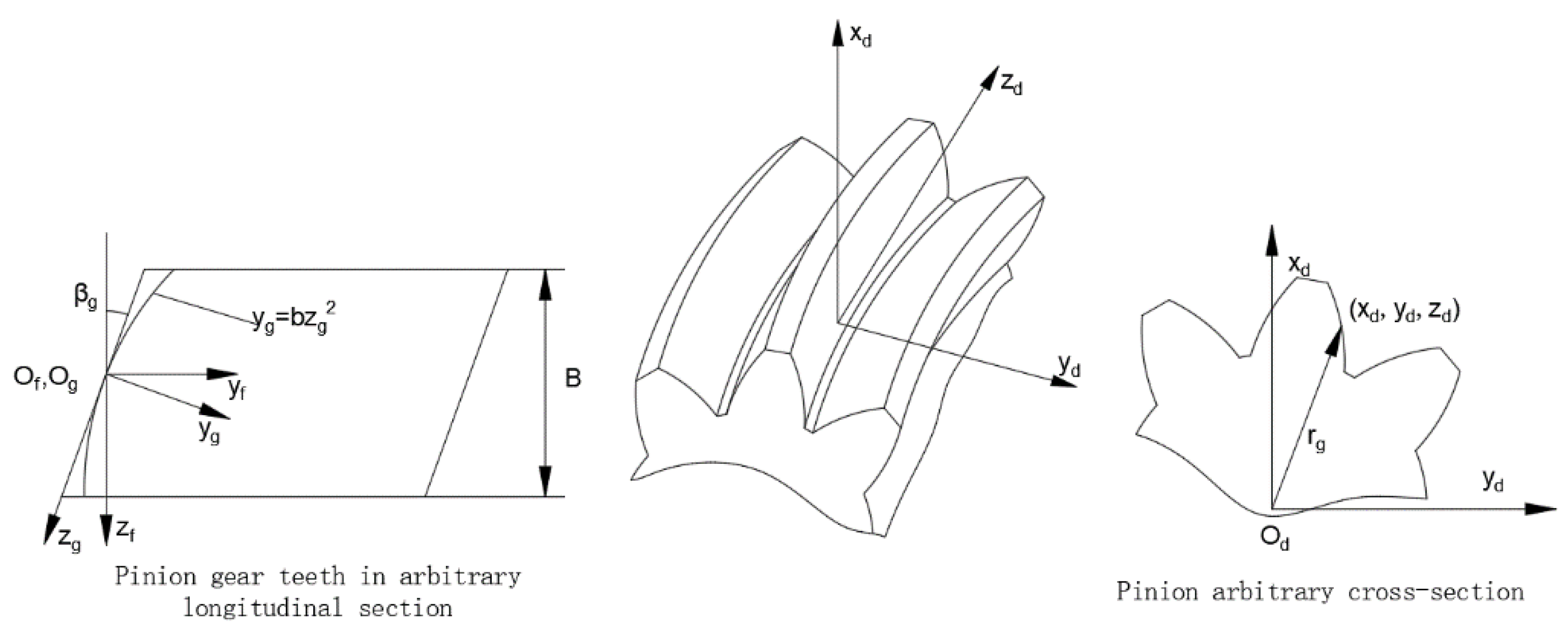
2. Mathematical Model

2.1. Dynamic Model of the Gear Transmission

In this work, we took a high-speed helical gear transmission of a BEV as the research object; the basic parameters and three-dimensional model of the input gear pair are shown in Table 2 and Figure 1, respectively.
A 12-DOF bending-torsion-axis-swing coupling dynamic model of helical gear transmission was established, as shown in Figure 2, where θ x , θ y are swings around the x- and y-axes, respectively; θ z is the torsional deformation around the z-axis; φ 1 is the angle between the meshing plane and the positive direction of the y-axis; β is the helical gear helix angle; T 1 , T 2 are driving and driven gear torque, respectively; O 1 , O 2 are geometric centers of driving and driven gears, respectively; k ix , k iy , k iz (i = 1,2) are the equivalent support stiffness of driving and driven gears in the x, y, and z directions, respectively; c ix , c iy , c iz (i = 1,2) are the equivalent support damping of driving and driven gears in the x, y, and z directions, respectively; k m , c m are time-varying meshing stiffness (TVMS) and meshing damping, respectively.
The set of differential equations for the kinetic model shown in Figure 2 is given by Newton’s second law in Equations (1)–(12)
x ¨ 1 m 1 + x ˙ 1 c 1 x + x 1 k 1 x = F x
y ¨ 1 m 1 + y ˙ 1 c 1 y + y 1 k 1 y = F y
z ¨ 1 m 1 + z ˙ 1 c 1 z + z 1 k 1 z = F z
θ ¨ 1 x I 1 + θ ˙ 1 x c i 1 x + θ 1 x k i 1 x = F z sin φ 1 R 1
θ ¨ 1 y I 1 + θ ˙ 1 y c i 1 y + θ 1 y k i 1 y = F z cos φ 1 R 1
θ ¨ 1 z I 1 = F y R 1 + T 1
x ¨ 2 m 2 + x ˙ 2 c 2 x + x 2 k 2 x = F x
y ¨ 2 m 2 + y ˙ 2 c 2 y + y 2 k 2 y = F y
z ¨ 2 m 2 + z ˙ 2 c 2 z + z 2 k 2 z = F z
θ ¨ 2 x I 2 + θ ˙ 2 x c i 2 x + θ 2 x k i 2 x = F z sin φ 1 R 2
θ ¨ 2 y I 2 + θ ˙ 2 y c i 2 y + θ 2 y k i 2 y = F z cos φ 1 R 2
θ ¨ 2 z I 2 = F y R 2 T 2
Based on the force and displacement decomposition, the radial dynamic meshing force, tangential dynamic meshing force, and axial dynamic meshing force in the above equation are expressed in parametric form as follows:
F = k m ( ( x 1 x 2 ) sin φ 1 cos β + ( y 1 y 2 + R 1 θ 1 z R 2 θ 2 z ) cos φ 1 cos β + ( z 1 z 2 + ( R 1 θ 1 x R 2 θ 2 x ) sin φ 1 + ( R 1 θ 1 y R 2 θ 2 y ) cos φ 1 ) sin β ) + c m ( ( x ˙ 1 x ˙ 2 ) sin φ 1 cos β + ( y ˙ 1 y ˙ 2 + R 1 θ ˙ 1 z R 2 θ ˙ 2 z ) cos φ 1 cos β + ( z ˙ 1 z ˙ 2 + ( R 1 θ ˙ 1 x R 2 θ ˙ 2 x ) sin φ 1 + ( R 1 θ ˙ 1 y R 2 θ ˙ 2 y ) cos φ 1 ) sin β )
F x = F cos β sin φ 1
F y = F cos β cos φ 1
F z = F sin β
where F is the dynamic meshing force in the direction of the meshing line;   x i , y i (i = 1,2) are the bending vibration displacement of driving and driven gears; z i (i = 1,2) is the axial vibration displacement of the driving and driven gears; I i (i = 1,2) is the rotational inertia of the driving and driven gears; R i (i = 1,2) is the radius of the base circle of the driving and driven gears; θ ix , θ iy (i = 1,2) are the swing displacement of driving and driven gears around the x- and y-axes, respectively; θ iz (i = 1,2) is the torsional displacement of the driving and driven gears around the z-axis; k ijx , k ijy , c ijx , c ijy (j = 1,2) are the stiffness and damping of the driving and driven gears corresponding to the torsional swing degrees of freedom, respectively. The formula for calculating meshing damping c m is as follows:
c m = 2 ξ k m I 1 I 2 I 1 R 2 + I 2 R 1
where ξ is a damping ratio; in this paper, it takes a value of 0.1.
In order to eliminate the influence of the gear rigid body angular displacement on the subsequent analysis, the relative angular displacement q is introduced to convert the angular displacement into linear displacement; it is expressed as follows:
q = R 1 θ 1 z R 2 θ 2 z
By substituting Formula (18) into Formulas (6) and (12), the torsional vibration equation can be simplified as follows:
q ¨ m e + F y = T 1 R 1
where m e is the equivalent torsional mass of the gear pair, which is expressed as
m e = I 1 I 2 I 1 R 2 2 + I 2 R 1 2

2.2. Excitation

It should be noted that the excitation factors of the gear transmission system are complex and diverse, including external excitation [18] caused by motor and load fluctuation, and internal excitation caused by stiffness [19,20], impact [21], error [22,23], and tooth surface friction [24,25]. Without loss of generality, only the TVMS is illustrated in this work; the other excitations are introduced in the same way without further explanation.
A method based on LTCA was applied to calculate the TVMS of gear pairs, which organically combines gear geometric analysis and mechanical analysis and can obtain the meshing stiffness curves of gear pairs under modified and error conditions. The calculation formula of meshing stiffness Kt is as follows:
K t = P Z
where P denotes force or moment and Z denotes line displacement or angular displacement deformation.
The loaded transmission error (LTE) Z of the gear pair is mainly caused by geometric transmission error, tooth bending deformation, and tooth contact deformation. The geometric transmission error is determined only by the design and machining of the tooth surface, and has no relationship with the magnitude of the load P. When the gear pair material, geometric parameters, and meshing position are certain, the tooth bending deformation and tooth contact deformation are determined by the load P. The relationship between each component and load P is as follows:
{ δ 1 ( P ) = c 1 δ 2 ( P ) = c 2 P δ 3 ( P ) = c 3 ( P ) 2 3
where c 1 , c 2 , c 3 are constants and δ 1 , δ 2 , δ 3 represent geometric transmission error, tooth bending deformation, and contact deformation, respectively.
Dividing a meshing period into n meshing positions, Zk(P) represents the loaded deformation at the kth meshing position under the nominal load P, and its value can be obtained by the gear LTCA procedure.
From this, the loaded deformation at the kth meshing position under the nominal load P can be obtained as follows:
Z k ( P ) = c 1 + c 2 P + c 3 ( P ) 2 3
According to the above method, three calculations under different loads are performed, and the coefficients c1, c2, and c3 can be determined by using the method of undermined coefficient; thus, the load as a function of deformation at the meshing position of the gear pair can be obtained, and the meshing stiffness at this meshing position under any load can be determined by this equation. By performing the above calculations for each meshing position, the meshing stiffness of each meshing position during the entire meshing period can be obtained, and finally, the meshing stiffness of each meshing position can be fitted to obtain the TVMS curve of the gear pair. The entire calculation process is shown in Figure 3.
The TVMS of the gear pair in Table 2 is calculated according to the method described in this paper. Figure 4 shows the calculated TVMS curve of the gear pair under a load torque of 382 N·m.

2.3. Tooth Surface Modification

Tooth surface modification can be divided into two categories: tooth profile modification and axial modification. Tooth profile modification can reduce the meshing impact of tooth pairs, thereby reducing the vibration and noise of the gear system; axial modification can make the load distribution on the tooth surface more uniform, reduce the bending and torsional deformation caused by the load, and improve the strength and vibration problems caused by the error along the tooth width direction during manufacturing and installation.
The tooth profile of the helical gear in this paper was achieved by tooth profile modification of the rack tool [8]. The normal tooth profile of the rack tool developed into a pinion is shown in Figure 5. The coordinate system Sa is the coordinate system established on the normal tooth profile of the tool, moving together with the tool; Sb is the coordinate system established on the normal tooth surface of the tool, moving together with the tool; Sc is the coordinate system established at the midpoint of the tooth width and pitch line of the transverse tooth surface of the rack tool; Sd is the follower coordinate system established on the pinion; Se is a fixed coordinate system built on the pinion; d0 is one-half of the normal tooth width; a is the parabolic coefficient of profile modification when the vertex is at Oa; αn is the normal pressure angle; u is the distance from the point on the tool’s normal tooth profile to the parabolic vertex. The coordinates of the normal tooth profile of the rack tool in the coordinate system Sa are expressed as follows:
r a ( u ) = [ u au 2 0 1 ] T
According to Figure 5, Figure 6 and Figure 7, the equation of pinion tooth surface can be obtained by coordinate transformation.
r d ( u , d 1 , φ 2 ) = M de M ec M cb M ba r a ( u )
According to the gear meshing principle,
f ( u , d 1 , φ 2 ) = n c · v c ( c , d ) = 0
where M de , M ec , M cb , M ba are coordinate transformation matrices; β is the helix angle; φ 2 is the rotation angle of the pinion during gear machining; d 1 is the distance between the coordinate system Sb and the coordinate system Sc along the direction of the O b z b axis; and r 1 is the radius of reference circle of pinion ( d 2 = φ 2 r 1 ).
M ba = [ cos α n sin α n 0 0 sin α n cos α n 0 d 0                 0 0                 1 0                       0 0                 0 1       ] M cb = [     1 0 0 0     0 cos β sin β d 1 sin β 0 sin β cos β d 1 cos β 0 0 0 1 ] M ec = [ 1 0 0 r 1 0 1 0 d 2 0 0 1 0       0 0 0 1       ] M de = [ cos φ 2 sin φ 2 0 0 cos φ 2 cos φ 2 0 0                 0 0                 1 0                 0 0                 0 1 ]
Axial modification in TCA can be realized directly in the tooth surface equation of the pinion [8]. Parabolic modification in the direction of the helix was used for the axial modification; the axial modification diagram is shown in Figure 8. The coordinate system Sf is an auxiliary coordinate system established on the pinion tooth profile; Sg is the coordinate system established on the pinion tooth profile along any helix angle direction. In the coordinate system Sg,
y g = bz g 2
where b is the parabolic coefficient of axial modification.
In the coordinate system Sf,
z f = z g cos β g + bz g 2 sin β g
y f = z g sin β g + bz g 2 cos β g
Compared to the unmodified tooth surface, the value of the change in coordinates of the modified tooth surface is
Δ y = bz g 2 cos β g
According to Equation (28) and Figure 8,
z g = cos β g + cos 2 β g + 4 bz f sin β g 2 b sin β g
Inserting Equation (31) into Equation (30), we can obtain the following:
Δ y = b ( cos β g + cos 2 β g + 4 bz f sin β g 2 b sin β g ) 2 cos β g
where β g = arctan ( r g tan β / r 1 )   and r g = x d 2 + y d 2 , z f = z d .
According to Equation (32), the coordinates of the pinion tooth surface after tooth profile modification and axial modification can be obtained as follows:
r d ( u , d 1 , φ 2 ) = M de M ec M cb M ba r a ( u ) + [ 0 Δ y 0 0 ]

2.4. The Global Optimization Model

Since the genetic algorithm has good global search capability and can control the search process adaptively to find the optimal solution, in this paper, we selected the genetic algorithm combined with TCA and LTCA of gears to optimize the tooth profile and axial modification coefficients.
The relative vibration acceleration on the gear pair meshing line is the most important aspect of vibration and noise in gear transmission systems, so the final optimization objective is to minimize the vibration acceleration on the meshing line direction over the entire working load range. Here, the minimum full working condition vibration acceleration is defined as the minimum of the mean value of the root mean square of the full working condition vibration acceleration. The objective function expression in the genetic algorithms is
min ( f ) = i = 1 N X N
with
X = j = 1 M Y ¨ 2 M
where X is the root mean square of the vibration acceleration at a certain working load under full working conditions, N is the number of the root mean square of the vibration acceleration in the working load range, Y is the vibration displacement in the direction of the meshing line, and M is the number of meshing points in one meshing period.
The specific optimization process based on the genetic algorithm is shown in Figure 9 below.

3. Experimental Verification and Analysis

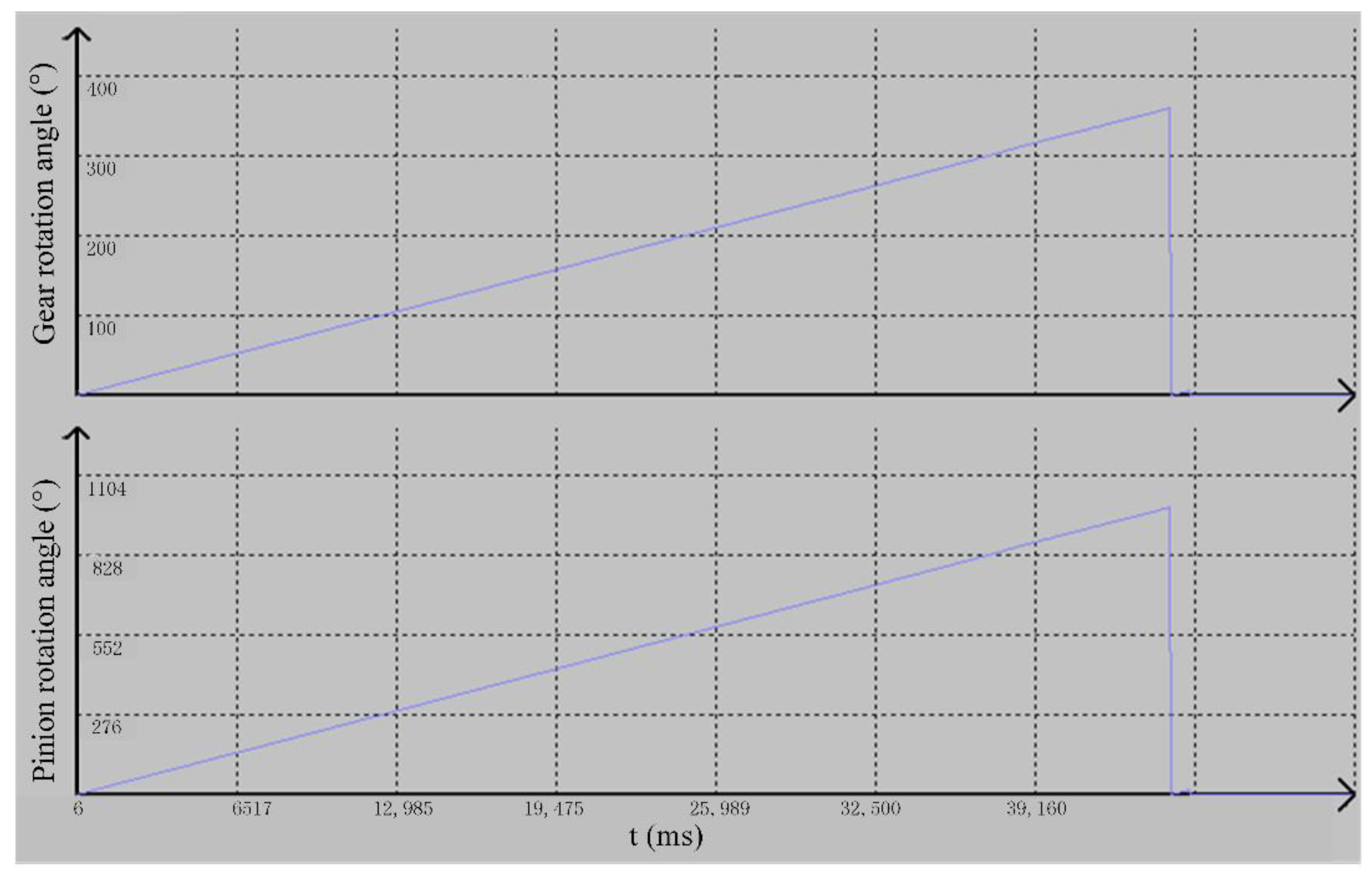
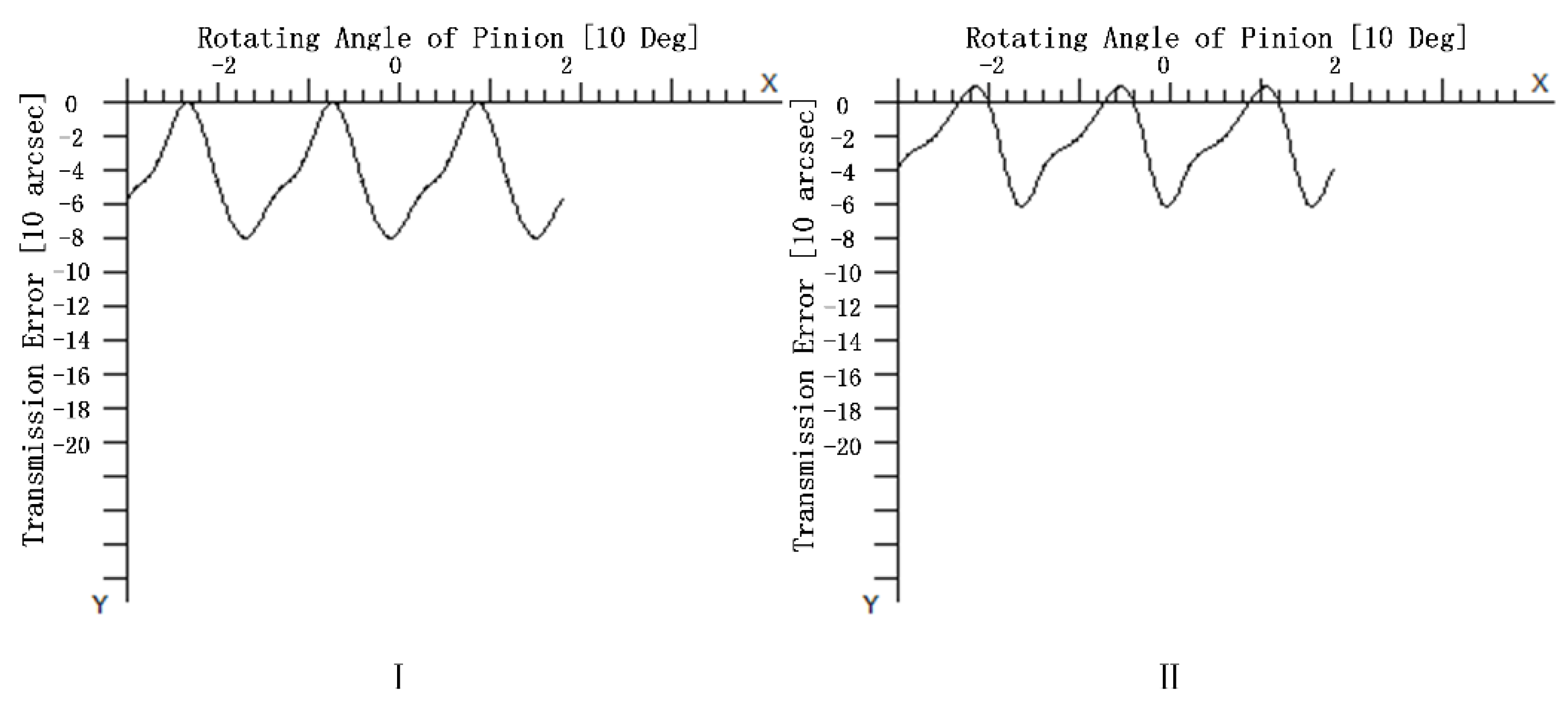
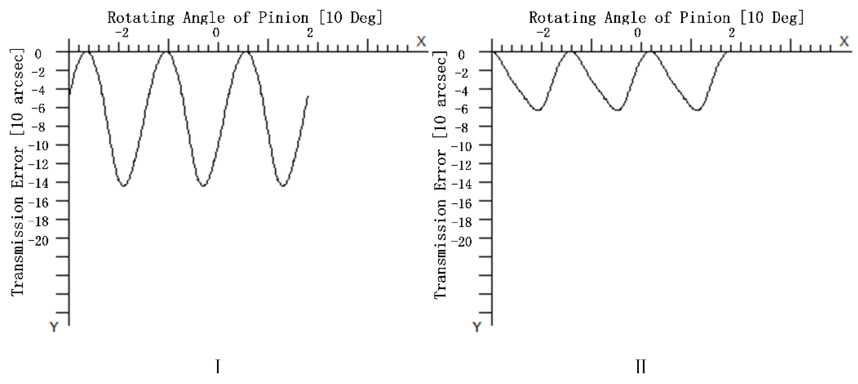
3.1. Experimental Verification of LTE Calculation Accuracy after Tooth Surface Modification

The accuracy of excitation calculation directly affects the subsequent analysis results. To ensure the accuracy of the TVMS calculation method based on LTE in this study, an experimental process was designed to check whether the LTE calculation results of the input gear pair were consistent with the experimental results before and after modification. The experimental scheme is shown in Figure 10. The circular grating model in the experiment was HEIDENHAIN RPN886; the number of lines was 90,000, with an accuracy of ±1″. The maximum rotational speed of the tacho-torquemeter was 8500 r/min, with a full scale of 2000 N·m and an accuracy of 2 N·m.
The electric motor needs to drive the gearbox at a relatively low speed to ensure the accuracy of the actual LTE, due to the meshing impact. The actual rotation angle of the driving pinion and the driven gear under load is measured by two circular gratings; the actual LTE δ can then be calculated as follows:
δ = Δ φ 2 Δ φ 2 = Δ φ 2 1 i 12 Δ φ 1
where Δ φ 1 and Δ φ 2 are the actual angle of the pinion and gear measured by the circular grating, and   i 12 represents the transmission ratio of the gear pair.
The experiment was carried out under a load of 100 N·m, at a speed of 14 r/min, and the tooth surface modification coefficients a and b were 1.048 × 10⁻² and 1.840 × 10⁻³, respectively. The experimental results are shown in Figure 11 and Figure 12. The calculation result of the simulation method in this study is shown in Figure 13.
As can be seen from Figure 12 and Figure 13, the amplitude of LTE calculated by the simulation method in this study is 6.9″ and the experiment result is 6.8″; there is only 1.5% difference between the results, that is, the LTE calculation method proposed in this study has high accuracy. Thus, the accuracy of the subsequent calculation of TVMS is ensured.

3.2. Optimal Tooth Surface Modification Scheme

We set the target gear working load range as 100 N·m–400 N·m and input speed as 5000 r/min (the corresponding vehicle speed is about 100 km/h). The optimal profile modification coefficients for the working loads of 100 N·m, 300 N·m, and 400 N·m and the full working condition were obtained through genetic algorithm optimization. The optimization results are shown in Table 3.
The LTE curves of the gears before and after modification under the above three groups of single loads were calculated using TCA and LTCA; the results are shown in Figure 14, Figure 15 and Figure 16. Comparing the results, it is obvious that the LTEs of the modified gears under each set of working loads were significantly reduced, indicating that appropriate tooth surface modification can effectively reduce the vibration of the gear system compared to the unmodified gears.
The vibration acceleration of the gear transmission system under stiffness excitation is influenced by the amplitude and mean value of TVMS. Figure 17, Figure 18 and Figure 19 show the TVMS of the gear pair before and after modification under the above three sets of loads. It can be seen from the figures that the magnitude of the TVMS decreases and the mean value of the stiffness increases after gear modification. This is consistent with the conclusion in [26] that reducing the amplitude of meshing stiffness and increasing the mean value of meshing stiffness can effectively reduce the vibration acceleration of the system.
Next, the vibration acceleration in the meshing line direction of the high-speed helical gear train was calculated for four modifying schemes at working loads of 100 N·m, 150 N·m, 200 N·m, 250 N·m, 300 N·m, 350 N·m, and 400 N·m, and the modifying effects of different modifying schemes were compared at full working conditions. It should be noted that the finer the load division, the more accurate the result is, but the computing time increases accordingly. Without loss of generality, the above division is made to illustrate the global optimal tooth surface modification method in this work.
Figure 20, Figure 21, Figure 22, Figure 23, Figure 24, Figure 25 and Figure 26 show the time domain diagrams of the vibration acceleration in the direction of the meshing line under different working loads for the above modification scheme. Table 4 shows the magnitude of the root mean square of the vibration acceleration of the gear at different working loads in the direction of the meshing line under the above modification scheme and without modification.
Comparing the vibration acceleration of each modification scheme under different working loads and the magnitude of the root mean square value of vibration acceleration under each working load, it can be seen that the vibration reduction effect of Scheme 4 is obvious under full working conditions compared with the other three modification schemes, although the vibration reduction effect of Scheme 4 is not always optimal under each working load. The vibration acceleration of Scheme 1 is less than that of Scheme 4 under a load of 100 N·m, but in other loads, the vibration suppression effect of Scheme 4 is more remarkable. Scheme 2 and Scheme 3 have good vibration suppression effects under high load; however, the vibration accelerations under low loads are obviously greater than for Scheme 4. That is, the optimal modifications to the full working conditions have better vibration reduction effects over the whole working load range compared to the optimal modifications for a specific load.

4. Conclusions

(1)
The bending-torsion-axis-swing coupling dynamics model of the helical gear system considering the stiffness excitation was established, the TVMS of the gear pair was calculated based on LTCA, and the calculation accuracy was verified by experiment.
(2)
Tooth profile and axial modifications were realized in TCA. The optimal tooth profile and axial modification parameters for the full working condition were obtained by using a genetic algorithm with the minimum root mean square of vibration acceleration as the optimization objective.
(3)
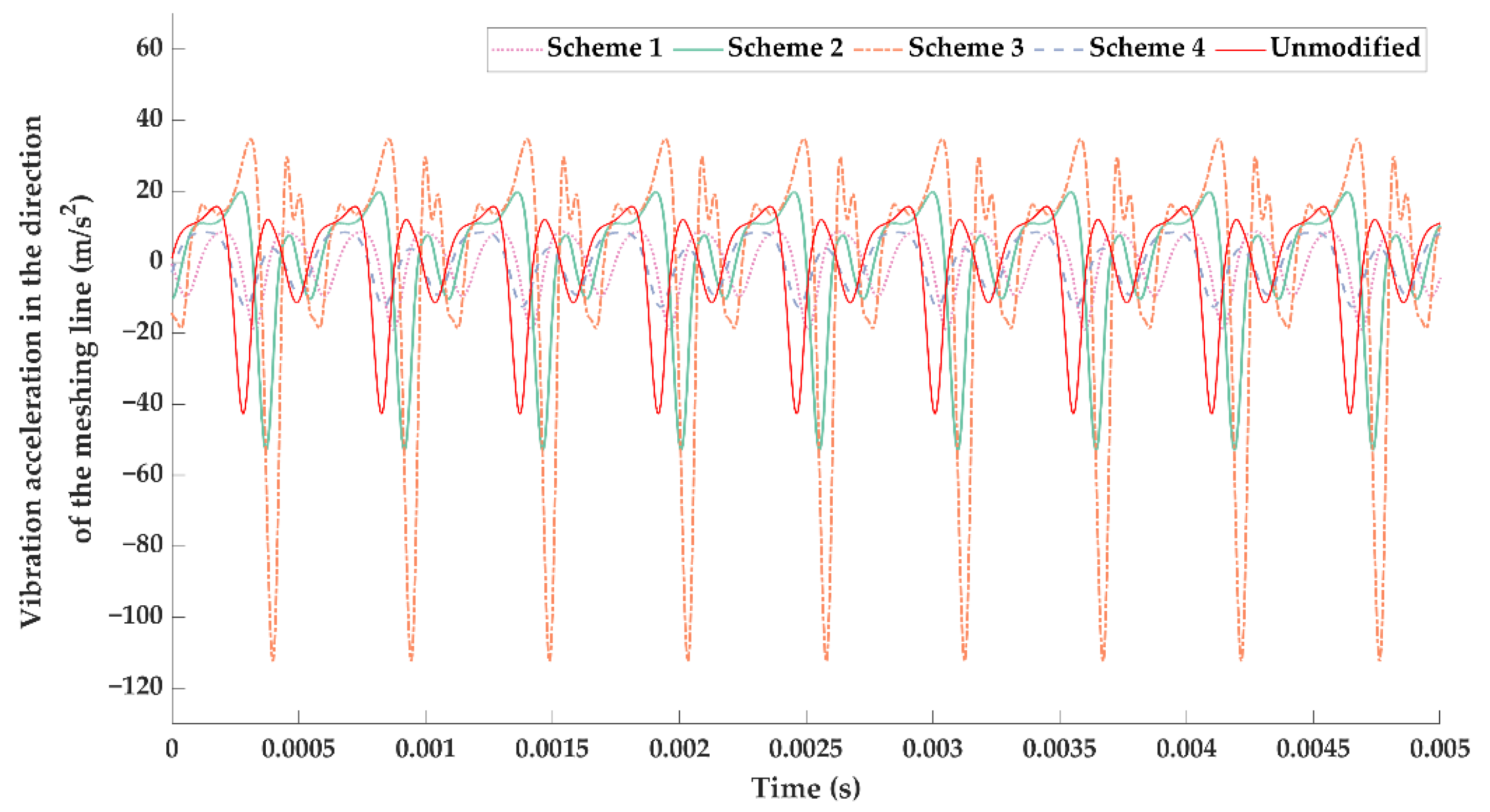
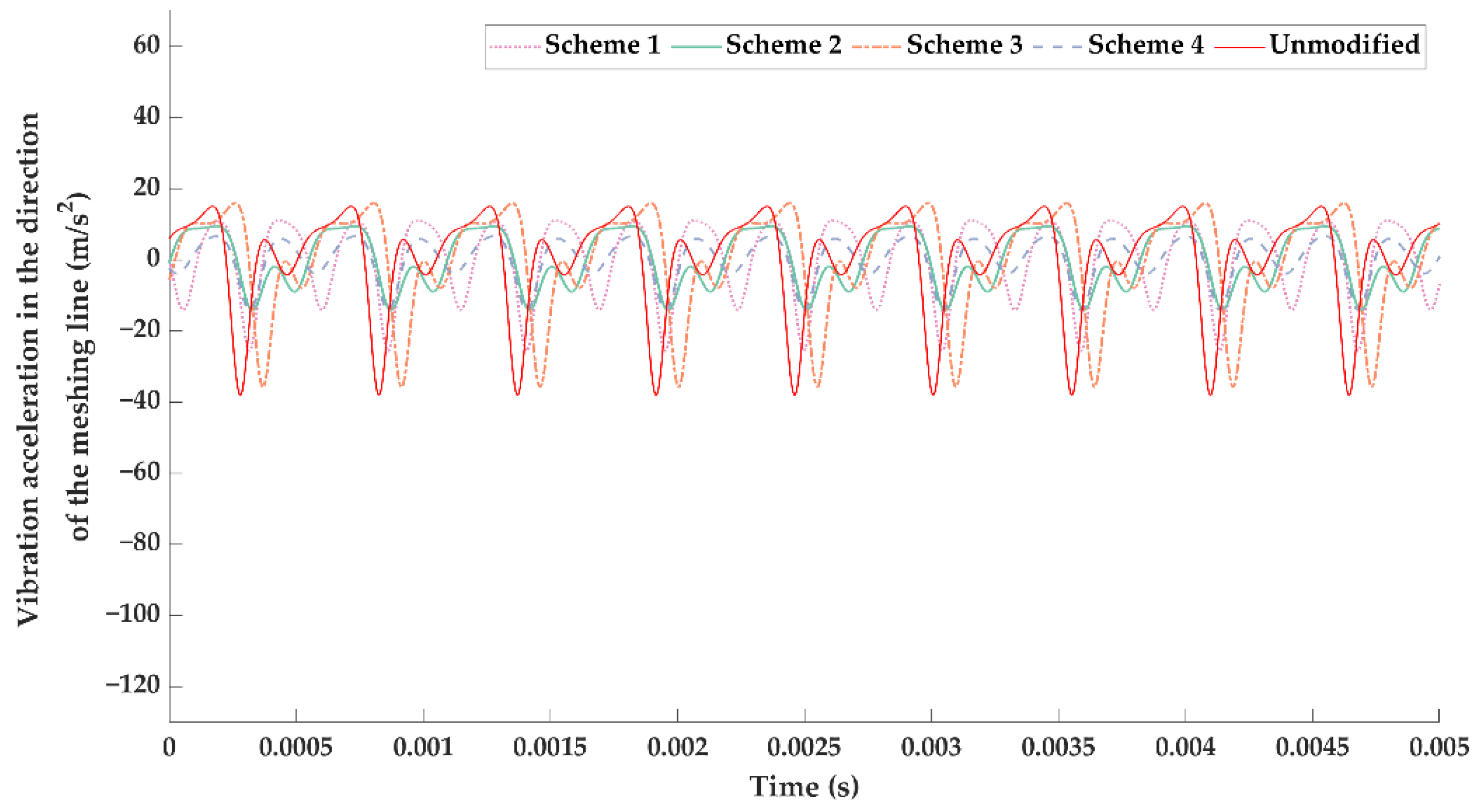
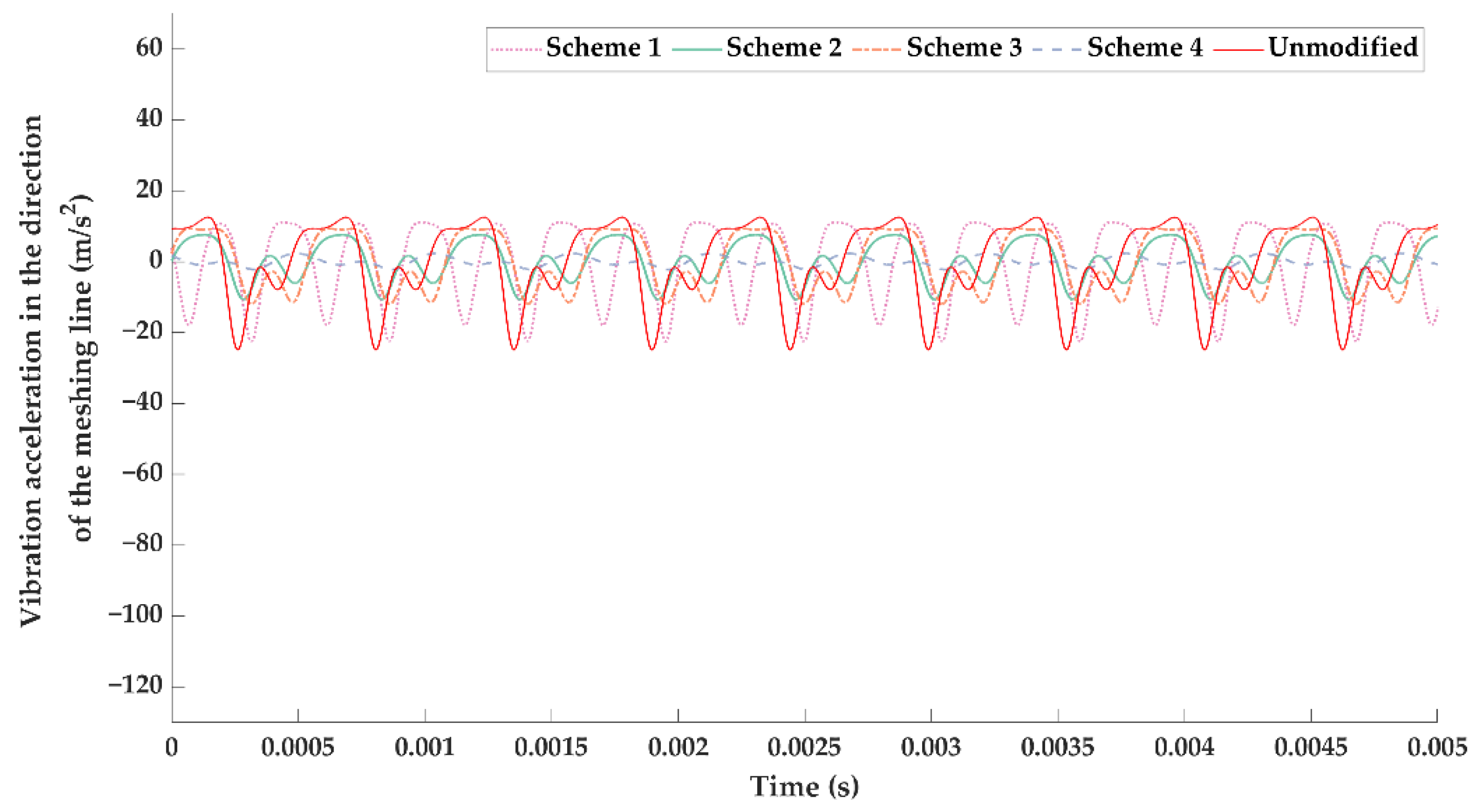
The vibration reduction effects of the optimal modification under a specific load and the full working condition were significantly different; the optimal modified tooth surface under full working condition had a better vibration suppression effect in the whole working load range. Therefore, more attention should be paid to the tooth surface modification under the full working conditions in BEV high-speed gear transmissions.

Author Contributions

Conceptualization, J.D. and L.H.; methodology, J.D. and L.H.; software, J.D. and L.H.; validation, J.D. and L.H.; formal analysis, J.M. and Y.Z.; investigation, L.H.; resources, J.D., J.M. and Y.Z.; data curation, L.H.; writing—original draft preparation, L.H.; writing—review and editing, J.D.; visualization, L.H.; supervision, J.D., J.M. and Y.Z.; All authors have read and agreed to the published version of the manuscript.

Funding

This work was supported in part by the National Natural Science Foundation of China (Grant No. 51705419 and Grant No. 61701397) and the Postdoctoral Research Project of Shaanxi Province (Grant No. 2018BSHEDZZ10).

Institutional Review Board Statement

Not applicable.

Informed Consent Statement

Not applicable.

Data Availability Statement

Not applicable.

Acknowledgments

We acknowledge the support provided for this study by Xi’an University of Technology, in the form of time and facilities.

Conflicts of Interest

The authors declare no conflict of interest.

References

  1. Liu, X.; Fang, Z.; Zhao, N.; Guo, H.; Shen, Y. Design and Analysis of Compensation Modification for Multi-Pair Contact of High-Contact-Ratio Helical Gears. J. Xi’an Jiao Tong Univ. 2020, 54, 56–64. [Google Scholar]
  2. Jiang, J.; Liu, Z.; Peng, X. Optimization Design of Vibration Reduction for Hypoid Gears with Ease-Off Flank Modification. J. South China Univ. Technol. (Nat. Sci. Ed.) 2020, 48, 134–141. [Google Scholar]
  3. Yang, S.; He, D.; Tang, J.; Wan, G. Research of the Design of Double Helical Gear Modification based on KISSsoft Software. J. Mech. Transm. 2018, 42, 1–6. [Google Scholar]
  4. Giorgio, B.; Marco, B.; Francesco, P. Optimum profile modifications of spur gears by means of genetic algorithms. J. Sound Vib. 2007, 313. [Google Scholar] [CrossRef]
  5. Samani, F.S.; Molaie, M.; Pellicano, F. Nonlinear vibration of the spiral bevel gear with a novel tooth surface modification method. Meccanica 2019, 54, 1071–1081. [Google Scholar] [CrossRef]
  6. Vilmos, S. Optimal Tooth Surface Modifications in Face-Hobbed Hypoid Gears. Key Eng. Mater. 2014, 572, 351–354. [Google Scholar] [CrossRef]
  7. Motahar, H.; Samani, F.S.; Molaie, M. Nonlinear vibration of the bevel gear with teeth profile modification. Nonlinear Dyn. 2016, 83, 1875–1884. [Google Scholar] [CrossRef]
  8. Bahk, C.J.; Parker, R.G. Analytical investigation of tooth profile modification effects on planetary gear dynamics. Mech. Mach. Theory 2013, 70, 298–319. [Google Scholar] [CrossRef]
  9. Wang, C. Study on 3-D modification for reducing vibration of helical gear based on TCA technology, LTCA technology and system dynamics. Mech. Syst. Signal Process. 2021, 146, 106991. [Google Scholar] [CrossRef]
  10. Wang, C. Multi-objective optimal design of modification for helical gear. Mech. Syst. Signal Process. 2021, 157, 107762. [Google Scholar] [CrossRef]
  11. Ghosh, S.S.; Chakraborty, G. On optimal tooth profile modification for reduction of vibration and noise in spur gear pairs. Mech. Mach. Theory 2016, 105, 145–163. [Google Scholar] [CrossRef]
  12. Cirelli, M.; Valentini, P.P.; Pennestrì, E. A study of the non-linear dynamic response of spur gear using a multibody contact based model with flexible teeth. J. Sound Vib. 2019, 445, 148–167. [Google Scholar] [CrossRef]
  13. Bruzzone, F.; Maggi, T.; Marcellini, C.; Rosso, C.; Delprete, C. Proposal of a novel approach for 3D tooth contact analysis and calculation of the static transmission error in loaded gears. Procedia Struct. Integr. 2019, 24, 178–189. [Google Scholar] [CrossRef]
  14. Liu, G.; Parker, R.G. Dynamic Modeling and Analysis of Tooth Profile Modification for Multimesh Gear Vibration. J. Mech. Des. 2008, 130. [Google Scholar] [CrossRef]
  15. Hu, Y.; Shao, Y.; Chen, Z.; Zuo, M.J. Transient meshing performance of gears with different modification coefficients and helical angles using explicit dynamic FEA. Mech. Syst. Signal Process. 2010, 25, 1786–1802. [Google Scholar] [CrossRef]
  16. Martini, A.; Bonelli, G.P.; Rivola, A. Virtual Testing of Counterbalance Forklift Trucks: Implementation and Experimental Validation of a Numerical Multibody Model. Machines 2020, 8, 26. [Google Scholar] [CrossRef]
  17. Schliermann, J.; Krüger, M. Bevel Gearbox with Vertical Drive Attachment for Industrial Trucks. ATZoffhighway Worldw. 2018, 11, 44–47. [Google Scholar] [CrossRef]
  18. Shen, J.; Cheng, H. Investigation on the Stationary Response of Gear Time-varying System Under Stochastic Excitation. J. Mech. Transm. 2021, 45, 37–40. [Google Scholar]
  19. Raghuwanshi, N.K.; Parey, A. Experimental measurement of gear mesh stiffness of cracked spur gear by strain gauge technique. Measurement 2016, 86, 266–275. [Google Scholar] [CrossRef]
  20. Pedersen, N.L.; Jørgensen, M.F. On gear tooth stiffness evaluation. Comput. Struct. 2014, 135, 109–117. [Google Scholar] [CrossRef]
  21. Jia, C.; Yao, L.; Zhang, J.; Fang, Z. Calculation of Mesh-in Impact of Modified Involute Helical Gears. J. Xi’an Jiao Tong Univ. 2020, 54, 58–65. [Google Scholar]
  22. Inalpolat, M.; Handschuh, M.; Kahraman, A. Influence of indexing errors on dynamic response of spur gear pairs. Mech. Syst. Signal Process. 2015, 60–61, 391–405. [Google Scholar] [CrossRef]
  23. Li, S. Finite element analyses for contact strength and bending strength of a pair of spur gears with machining errors, assembly errors and tooth modifications. Mech. Mach. Theory 2007, 42, 88–114. [Google Scholar] [CrossRef]
  24. He, S.; Gunda, R.; Singh, R. Effect of sliding friction on the dynamics of spur gear pair with realistic time-varying stiffness. J. Sound Vib. 2006, 301, 927–949. [Google Scholar] [CrossRef]
  25. Velex, P.; Sainsot, P. An analytical study of tooth friction excitations in errorless spur and helical gears. Mech. Mach. Theory 2002, 37, 641–658. [Google Scholar] [CrossRef]
  26. Zhao, N.; Guo, Z.Q.; Fu, C.X.; Lin, Y.H. The Effect of Meshing Stiffness and Meshing Damping on Dynamics Characteristic of Herringbone Gears. Sci. Technol. Eng. 2013, 13, 1757–1763. [Google Scholar]
Figure 1. Three-dimensional model: (I) BEV gearbox; (II) Helical gear pair.
Machines 09 00226 g001
Figure 2. Bend-torque-shaft-swing coupling model for high-speed stage helical gear transmission system.
Machines 09 00226 g002
Figure 3. TVMS calculation process for the gear pair.
Machines 09 00226 g003
Figure 4. TVMS curve.
Machines 09 00226 g004
Figure 5. Normal tooth profile of rack cutter.
Machines 09 00226 g005
Figure 6. Rack projection.
Machines 09 00226 g006
Figure 7. Pinion and rack meshing.
Machines 09 00226 g007
Figure 8. Diagram of axial modification.
Machines 09 00226 g008
Figure 9. Genetic algorithm optimization process.
Machines 09 00226 g009
Figure 10. Experimental scheme.
Machines 09 00226 g010
Figure 11. Actual rotation angles of the pinion and the gear.
Machines 09 00226 g011
Figure 12. Actual LTE of the gear pair.
Machines 09 00226 g012
Figure 13. LTE of the gear pair calculated by the simulation method.
Machines 09 00226 g013
Figure 14. LTE curves at a load of 100 N·m: (I) Unmodified; (II) Modification.
Machines 09 00226 g014
Figure 15. LTE curves at a load of 300 N·m: (I) Unmodified; (II) Modification.
Machines 09 00226 g015
Figure 16. LTE curves at a load of 400 N·m: (I) Unmodified; (II) Modification.
Machines 09 00226 g016
Figure 17. TVMS curve at a load of 100 N·m.
Machines 09 00226 g017
Figure 18. TVMS curve at a load of 300 N·m.
Machines 09 00226 g018
Figure 19. TVMS curve at a load of 400 N·m.
Machines 09 00226 g019
Figure 20. Vibration acceleration in the direction of the gear meshing line at a load of 100 N·m.
Machines 09 00226 g020
Figure 21. Vibration acceleration in the direction of the gear meshing line at a load of 150 N·m.
Machines 09 00226 g021
Figure 22. Vibration acceleration in the direction of the gear meshing line at a load of 200 N·m.
Machines 09 00226 g022
Figure 23. Vibration acceleration in the direction of the gear meshing line at a load of 250 N·m.
Machines 09 00226 g023
Figure 24. Vibration acceleration in the direction of the gear meshing line at a load of 300 N·m.
Machines 09 00226 g024
Figure 25. Vibration acceleration in the direction of the gear meshing line at a load of 350 N·m.
Machines 09 00226 g025
Figure 26. Vibration acceleration in the direction of the gear meshing line at a load of 400 N·m.
Machines 09 00226 g026
Table 1. Symbol summary.
SymbolDescription
aParabolic coefficient of profile modification
bParabolic coefficient of axial modification
cix, ciy, cizEquivalent support damping of driving and driven gears in Xx, y, and z directions (i = 1,2)
cmMeshing damping
cijx, cijyDamping of the driving and driven gears corresponding to the torsional swing degrees of freedom (j = 1,2)
c 1 , c 2 , c 3 Constants
d0One-half of the normal tooth width
d1Distance between the coordinate system Sb and the coordinate system Sc along the direction of O b z b axis
FDynamic meshing force in the direction of the meshing line
i12Transmission ratio of the gear pair
IiRotational inertia of the driving and driven gears (i = 1,2)
kix, kiy, kizEquivalent support stiffness of driving and driven gears in x, y, and z directions (i = 1,2)
kmTime-varying meshing stiffness
kijx, kijyStiffness of the driving and driven gears corresponding to the torsional swing degrees of freedom (j = 1,2)
KtMeshing stiffness
meEquivalent torsional mass of the gear pair
Mde, Mec, Mcb, MbaCoordinate transformation matrices
MNumber of meshing points in one meshing period
NNumber of the root mean square of the vibration acceleration in the working load range
O1, O2Geometric centers of driving and driven gears
PForce or moment
qRelative angular displacement
RiRadius of the base circle of the driving and driven gears (i = 1,2)
SaCoordinate system established on the normal tooth profile of the tool, moving together with the tool
SbCoordinate system established on the normal tooth surface of the tool, moving together with the tool
ScCoordinate system established at the midpoint of the tooth width and pitch line of the transverse tooth surface of the rack tool
SdFollower coordinate system established on the pinion
SeFixed coordinate system built on the pinion
SfAuxiliary coordinate system established on the pinion tooth profile
SgCoordinate system established on the pinion tooth profile along any helix angle direction
T1, T2Driving and driven gear torque
uDistance from the point on the tool’s normal tooth profile to the parabolic vertex
xi, yiBending vibration displacement of driving and driven gears (i = 1,2)
XRoot mean square of the vibration acceleration at a certain working load under full working conditions
YVibration displacement in the direction of the meshing line
ziAxial vibration displacement of the driving and driven gears (i = 1,2)
ZLine displacement or angular displacement deformation
βHelical gear helix angle
δ 1 Geometric transmission error
δ 2 Tooth bending deformation
δ 3 Contact deformation
Δ φ 1 , Δ φ 2 Actual angle of the pinion and gear measured by the circular grating
θx, θySwings around the x- and y-axes
θzTorsional deformation around the z-axis
ξDamping ratio
φ 1 Angle between the meshing plane and the positive direction of the y-axis
φ 2 Rotation angle of the pinion during gear machining
Table 2. Basic parameters of the gear pair.
ParametersPinionGear
Number of teeth2259
Spiral directionRHLH
Normal module (mm)2
Normal pressure angle (°)18.5
Helix angle (°)32
Face width (mm)3331.5
Profile shift coefficient (mm)0.4578−0.31
Elastic modulus (GPa)210
Table 3. Genetic algorithm optimization results.
Modification SchemeTooth Profile Modification Coefficient: aAxial Modification
Coefficient: b
Scheme 1 (Optimum modification at a load of 100 N·m)1.048 × 10−21.840 × 10−3
Scheme 2 (Optimum modification at a load of 300 N·m)8.600 × 10−33.950 × 10−3
Scheme 3 (Optimum modification at a load of 400 N·m)8.540 × 10−34.890 × 10−3
Scheme 4 (Optimum modification under full working conditions)7.450 × 10−32.540 × 10−3
Table 4. Root mean square value of vibration acceleration in the direction of the meshing line under different working loads (m/s2).
Working LoadScheme 1Scheme 2Scheme 3Scheme 4Unmodified
100 N·m10.180640.062240.382012.679112.8866
150 N·m8.221618.075934.70846.668915.2156
200 N·m10.90457.833314.02315.900613.6982
250 N·m10.99605.61437.91891.335510.7765
300 N·m9.48722.23517.15503.675110.1485
350 N·m11.32763.66454.78366.572410.7539
400 N·m11.57646.99055.693010.786412.6968
Average10.384912.068016.38066.802612.3109
Publisher’s Note: MDPI stays neutral with regard to jurisdictional claims in published maps and institutional affiliations.

