
Research on Path Planning Algorithm for Driverless Vehicles


1
School of Information Science and Electrical Engineering, Shandong Jiaotong University, Jinan 250357, China
2
School of Control Science and Engineering, Shandong University, Jinan 250061, China
3
State Key Laboratory of Automotive Simulation and Control, Jilin University, Changchun 130022, China
*
Authors to whom correspondence should be addressed.
Mathematics 2022, 10(15), 2555; https://0-doi-org.brum.beds.ac.uk/10.3390/math10152555
Submission received: 20 June 2022
/
Revised: 18 July 2022
/
Accepted: 20 July 2022
/
Published: 22 July 2022
(This article belongs to the Special Issue Recent Advances in Computational Intelligence and Its Applications)
Abstract
:In a complex environment, although the artificial potential field (APF) method of improving the repulsion function solves the defect of local minimum, the planned path has an oscillation phenomenon which cannot meet the vehicle motion. In order to improve the efficiency of path planning and solve the oscillation phenomenon existing in the improved artificial potential field method planning path. This paper proposes to combine the improved artificial potential field method with the rapidly exploring random tree (RRT) algorithm to plan the path. First, the improved artificial potential field method is combined with the RRT algorithm, and the obstacle avoidance method of the RRT algorithm is used to solve the path oscillation; The vehicle kinematics model is then established, and under the premise of ensuring the safety of the vehicle, a model predictive control (MPC) trajectory tracking controller with constraints is designed to verify whether the path planned by the combination of the two algorithms is optimal and conforms to the vehicle motion. Finally, the feasibility of the method is verified in simulation. The simulation results show that the method can effectively solve the problem of path oscillation and can plan the optimal path according to different environments and vehicle motion.
Keywords:
driverless; artificial potential field method; rapidly exploring random tree algorithm; model predictive controlMSC:
93C85; 93C951. Introduction
With the development of the era of big data, the research and development of driverless technology is also making continuous progress. As an important part of unmanned driving technology, path planning has emerged in recent years with various related algorithms. Common ones are the artificial potential field method and the rapidly expanding random tree (rapidly-exploring random tree, RRT) algorithm.
The RRT algorithm is the most basic global path planning algorithm. Its basic idea is to sample and grow in the environment from the root node until it finds the target. No matter how complicated the environment, it can always find a path. However, this algorithm has a low convergence speed. In order to speed up the convergence speed of the RRT algorithm by gradually changing the sampling area and speeding up the sampling speed, the convergence speed can be improved and an appropriate path can be found quickly [1,2].
Because the randomness of the algorithm is too large, the RRT algorithm samples in the space, which is easy to generate redundant branches. In the process of tree sampling growth, pruning redundant paths can improve the planning efficiency [3]. In the movement of the robot and the manipulator, the RRT algorithm is combined with the artificial potential field method and the extended algorithm, which can remove redundant branches, select appropriate nodes and complete the path planning [4,5].
Based on the traditional RRT algorithm, an improved RRT* algorithm is generated which can quickly plan the shortest path in line with the driving of a driverless vehicle by combining it with heuristic double sampling [6]. In mobile robot path planning, MOD-RRT* can select the best node in the shortest time and generate the optimal path [7]. In the unmanned path planning, the bidirectional RRT is used for sampling and exploration from the target position and the starting point at the same time, and the separation law is added to the collision detection to improve the planning efficiency [8]. In the RRT algorithm, the adaptive is added to reduce the randomness of the sampling, and the ap-propriate node is selected by using the relationship between the angle and the distance, and the path is optimized [9,10]. The RRT algorithm is used to help the artificial potential field method escape the local minimum trap, but the path oscillation still cannot be solved and the randomness of the selected virtual target point position is too large, which affects the efficiency of path planning [11]. The RRT algorithm is used to help the artificial potential field method escape the local minimum trap, but the path oscillation still cannot be solved and the randomness of the selected virtual target point position is too large, which affects the efficiency of path planning [12]. For the RRT algorithm, its sampling and obstacle avoidance functions that are not constrained by the environment can improve the efficiency of path planning to a certain extent.
The artificial potential field method relies on the gravitational field produced by the target and the repulsive force field produced by the obstacle to plan the path. It is often used for path planning of UAV, robots and driverless vehicles. In the braking process of the vehicle, the longitudinal safety distance model and the side-slip angle constraint are added to the potential field function to improve the obstacle avoidance accuracy [13]. The artificial potential field theory is added to the vehicle cooperative control model, and on the premise of ensuring safe driving, it also improves driving comfort and improves traffic congestion [14]. However, the algorithm suffers from three flaws, namely local minima, target unreachability and path oscillation. In order to solve the local minimum and target unreachable defects existing in the artificial potential field method. In the path planning of the mobile robot, in order to improve the efficiency of the robot, the local minimal value problem can be solved by improving the corresponding potential field function according to the principle of the artificial potential field method [15,16]. While improving the repulsion potential field function, a virtual target point is added which can escape in time when the path falls into a defect, which solves the problem of an unreachable target [17]. The artificial potential field method is combined with the ant colony algorithm to select the appropriate path point in each iteration until the target is reached, which can effectively solve the target unreachable and local minimum problems [18]. In robot obstacle avoidance, the artificial potential field method combined with the D* algorithm is used to reach the dynamic target and avoid the dynamic obstacles [19,20]. In UAV obstacle avoidance, a rotational potential field is designed to be added to the artificial potential field to solve the local minima [21]. In order to study the working characteristics of complex snake-like robots in water, the IB-LBM method is combined with the improved artificial potential (AF), which can effectively eliminate the local minimum of the artificial potential field method [22].
In the path planning of a driverless vehicle, introducing the relative speed factor and applying a rotating repulsion force with a certain angle can jump out of the local minimum trap and eliminate the unreachable target defect [23,24,25]. Based on the vehicle dynamics model, the local minimum value is jumped out by controlling the vehicle steering and setting an appropriate step size [26]. Combining the A* algorithm with the improved artificial potential field method, the A* algorithm is used to divide the path delineated by the artificial potential field law into multiple sub-target points which can reduce the probability of the vehicle falling into a local minimum while also switching the path in time to escape from the local minimum trap [27]. When the path planned by the artificial potential field method oscillates when approaching an obstacle, the oscillations can be eliminated by improving the repulsive field method, but this method is applicable to simple environments and still generates oscillations when the path is too close to the obstacle [28]. In the vehicle driving environment, introducing safe distances into the artificial potential field method and decomposing repulsive forces by redefining the influence range of obstacles allows the vehicle to avoid falling into local minima while avoiding obstacles [29]. By adding the angle function and fuzzy control idea to the traditional artificial potential field method to control the stability of the path, the path planned by this method can quickly jump out of the local minima trap and remain stable [30]. By discretizing the obstacle boundary in the road, establishing the road boundary potential field and adding relevant constraints to improve the safety of obstacle avoidance, and at the same time add random escape force, so as to jump out of the local minimum [31,32]. In the established safety potential field model, a unified function of vehicle potential field based on Lennard-Jones potential is established. The vehicle acceleration parameters are taken into account in the vehicle potential field model to solve the local minimum defect [33]. The normal driving environment of the vehicle is often unknown, and the obstacles that appear must be discretized and polynomial curves are added to the artificial potential field to plan a path with the optimal curvature to ensure the vehicle travels [34,35]. In the speed control of the vehicle, the desired speed can be obtained by imitating the driver’s behavior by adding an artificial potential field to the path planner [36,37,38]. When there is an obstacle in front of the road, the planner can control the vehicle to decelerate in time [39].
In the path planning of unmanned vehicles, the primary goal is that the path can safely avoid obstacles and satisfy the vehicle motion. Since the environment is complex and unknown, the thermodynamics and wear state of the tire affect the dynamic characteristics of the tire, thereby changing the vehicle’s behavior. Therefore, factors such as the state of vehicle tires should be considered in path planning. Considering changes in systems and boundary conditions on different road surfaces, and learning about tire dynamic limits by developing simulated driver behavior [40]. In vehicle simulation tests, the multi-physics Pacejka’s magic formula tire model is often used to represent tire characteristics. It reproduces the effects of temperature, pressure and wear on the dynamic behavior of the tire, which provides an idea for planning the optimal path [41,42].
The biggest advantage of linear MPC is that it is simple to calculate and can ensure good real-time performance. The optimal result of nonlinear MPC in each control cycle is not easy to determine; it will fall into local optimum and vehicle dynamics, and physical constraints and obstacles around the environment will greatly affect the trajectory tracking performance of nonlinear MPC [43,44]. Using a linear four-wheel vehicle model in the controller can efficiently distribute control work to each actuator. At this time, the use of linear MPC theory can reduce the computational burden of nonlinear MPC [45]. Considering the dynamic characteristics of tires in the four-wheel vehicle model, the solution time of linear MPC is reduced under the premise of a stable tracking trajectory. Compared with nonlinear MPC, the real-time performance of linear MPC is significantly improved [46]. The road factors are added to the linear MPC steering controller, a four-wheel vehicle model considering vertical loads is established, and the inclination angle and roll angle are used as constraints so that the linear MPC has good robustness on complex roads while meeting the real-time requirements [47,48].
The core of the improvement methods in the above literature is to improve the repulsion potential field function. This improved method can solve local minima and target unreachable defects, but cannot effectively solve the path oscillation problem. Therefore, aiming at the problem of path oscillation, this paper proposes a path planning algorithm that combines the improved artificial potential field method with the Rapidly Exploring Random Tree (RRT) algorithm. This method uses the improved artificial potential field method to plan the path from the initial position, switches the RRT algorithm when approaching the target, uses the sampling function of the RRT algorithm in the environment and the obstacle collision detection method to plan the remaining path, eliminates oscillation and reaches the target. After the MPC trajectory tracking simulation comparison, the path planned by this method is the optimal one.
2. Materials and Methods
2.1. Traditional Artificial Potential Field Method
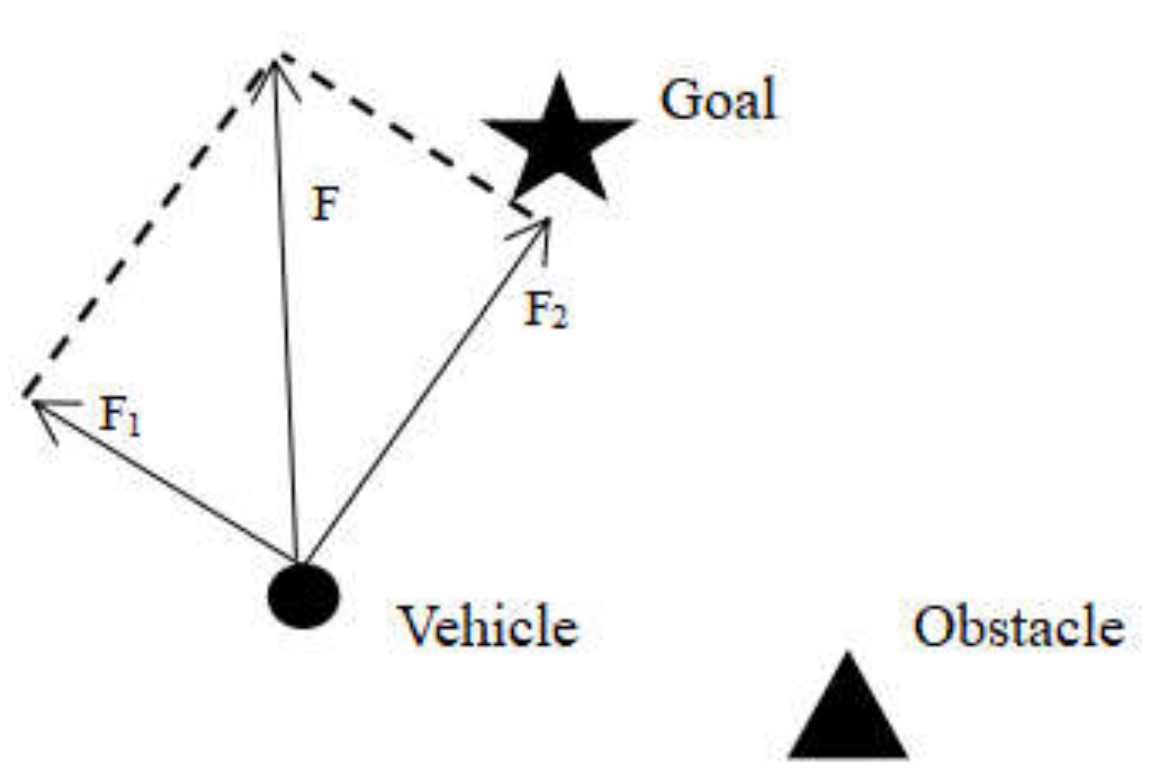
The gravitational force generated by the target in the artificial potential field method makes the vehicle move in the target direction. The repulsive force generated by the obstacle causes the vehicle to avoid the obstacle.
In Figure 1, F1 is the repulsion force generated by the obstacle to the vehicle, F2 is the gravitational force of the target on the vehicle, F is the sum of the repulsion force and the gravitational force at the current position, and the direction is the vehicle’s forward direction.
Among them, the expressions of attraction and repulsion are:
In the above formula, and represent the attractive force and repulsion force respectively, and represent the attractive force gain coefficient and the repulsion force gain coefficient respectively, is the distance between the target and the vehicle (this paper takes the Euclidean distance), is the distance between the obstacle and the current position of the vehicle, and is the maximum distance between the obstacle and the vehicle to generate repulsion.
2.2. Improved Artificial Potential Field Method
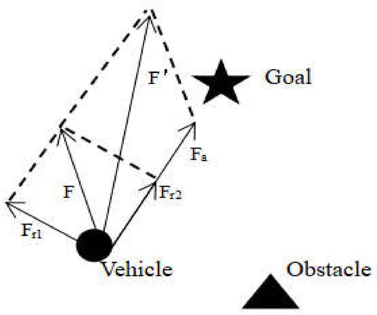
Aiming at the problems of local minimum points and unreachable targets in the path planning of the traditional artificial potential field method, we can start by modifying the expression of the repulsion force. The original repulsion potential field function is multiplied by the relative distance between the target and the current vehicle (n is a positive integer), and when the vehicle reaches the target, its repulsion can be reduced to zero, effectively solving the above defects [49].
Improved repulsion expression:
Among
The principle of the improved artificial potential field method is shown in Figure 2.
The above improvements work well for a single obstacle or a few obstacles around the target, but the planned path is not optimal. When there are multiple obstacles around the target, the path will generate oscillation when approaching the obstacles.
2.3. Principle of RRT Algorithm
2.3.1. RRT Algorithm
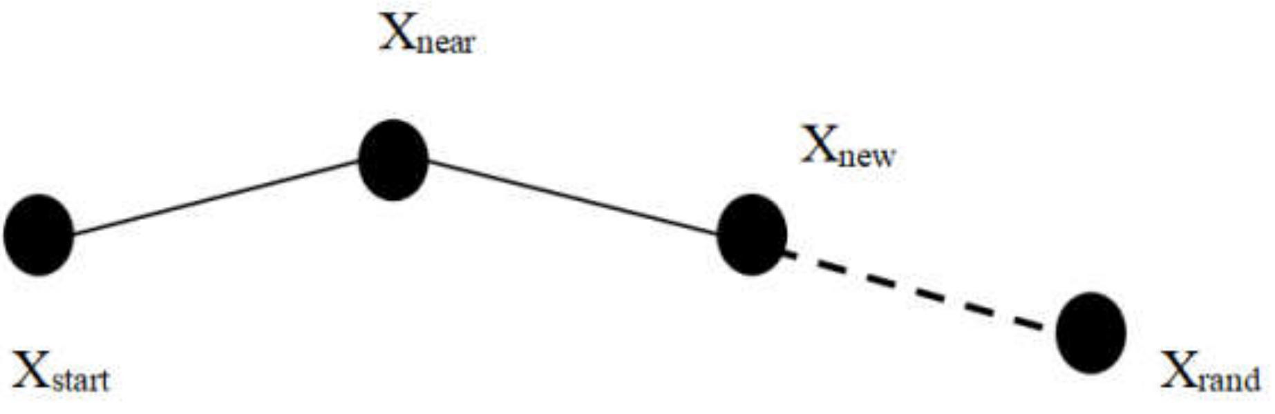
The rapidly exploring random tree (RRT) algorithm can quickly calculate, avoid obstacles and find targets in complex environments. The basic idea is to sample and grow in the environment from the root node until the target is found. The schematic diagram of the RRT algorithm is described in Figure 3.
2.3.2. RRT Algorithm Collision Detection
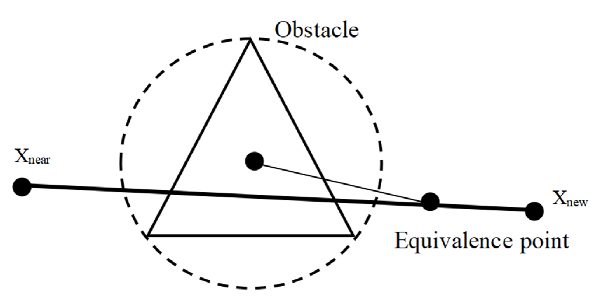
Most of the obstacles encountered in path planning in an unknown environment are irregular, and it is very troublesome to perform collision detection. Reference [50] proposes to simplify irregular obstacles into regular circles and divide the path to be detected into equal points and connect them to the centre of the circle for distance judgment to avoid obstacles, as shown in Figure 4.
Path collision detection formula:
In the above formula, = 0, 1, 2, …, represents the bisector point, represents the coordinates of the centre of the circle, and represents the radius of the obstacle circle. When the distance between a bisector point and the centre of the circle is less than or equal to , the path fails collision detection.
2.4. MPC Trajectory Tracking Controller Design
2.4.1. Vehicle Kinematics Model
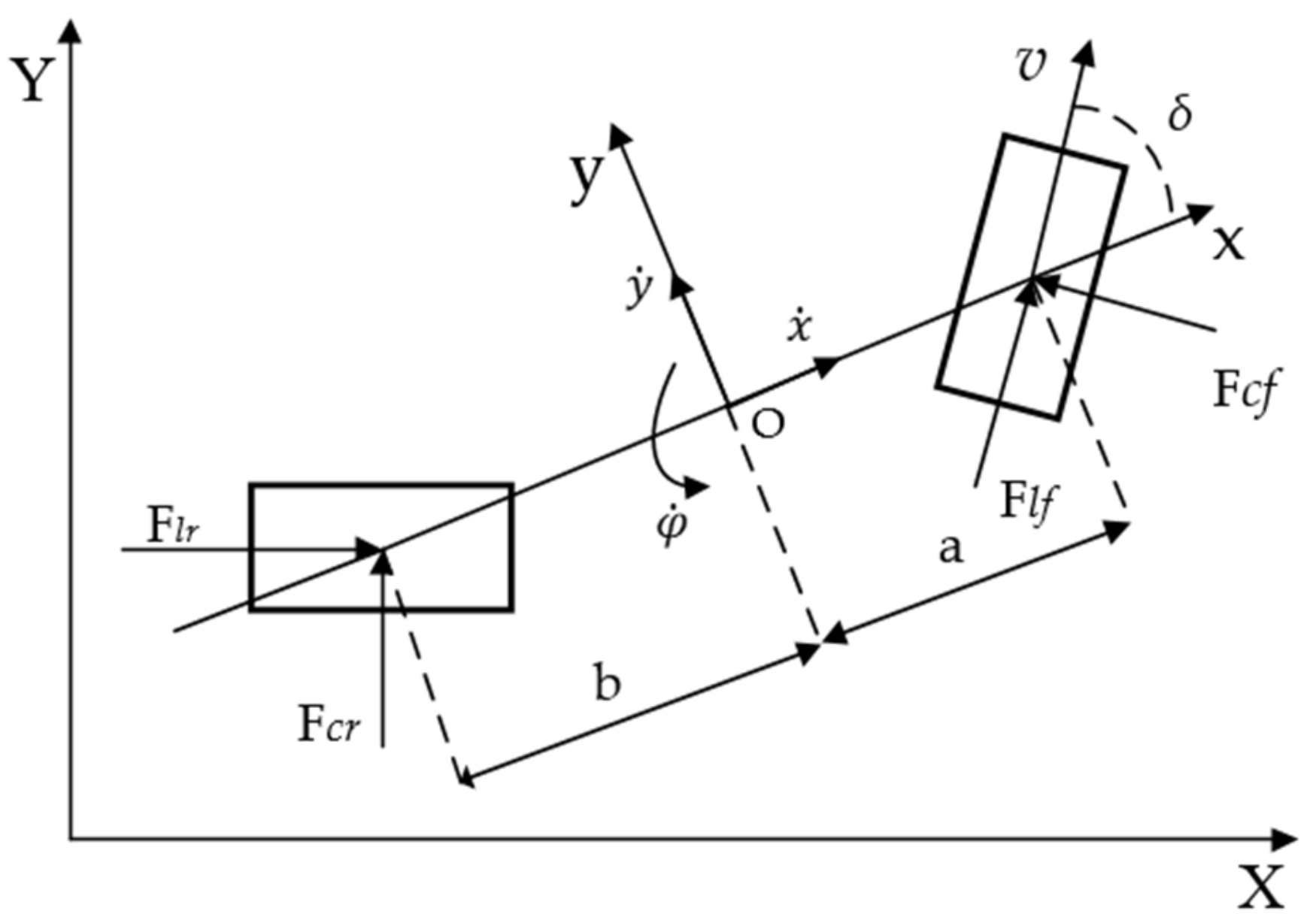
In order to reflect the real situation of the vehicle during the driving process, a three-degree-of-freedom vehicle dynamics model is selected, as shown in Figure 5.
In the coordinate system, the vehicle dynamics equation is as follows:
Among them, is the vehicle mass, is the distance between the center of mass and the front axle, is the distance between the center of mass and the rear axle, is the moment of inertia, and are the lateral forces on the front and rear tires of the vehicle, and are the longitudinal forces exerted on the front and rear tires of the vehicle, is the yaw angle of the vehicle, and is the steering angle of the front wheel of the vehicle.
2.4.2. MPC Objective Function Design
Generally, the MPC controller selects the output variables of the system by optimizing the objective function with constraints [51]. To ensure that the objective function can ensure that the unmanned vehicle can track the reference trajectory more stably, the following form is specially adopted [52]:
Among them, is the prediction time domain, is the control time domain, , is the weight matrix, is the reference output, is the control increment, is the weight coefficient and is the relaxation factor.
To further improve the accuracy and stability of the vehicle following the reference trajectory, it is necessary to constrain the front wheel steering angle and yaw angle of the vehicle [53]. this includes the front-wheel steering angle constraint: .
To facilitate the writing of computer language, Equation (8) is converted into a quadratic programming form with constraints through matrix operations:
Among them, ; ; is the tracking error in the prediction time domain.
2.5. Combination of Improved Artificial Potential Field Method and RRT Algorithm
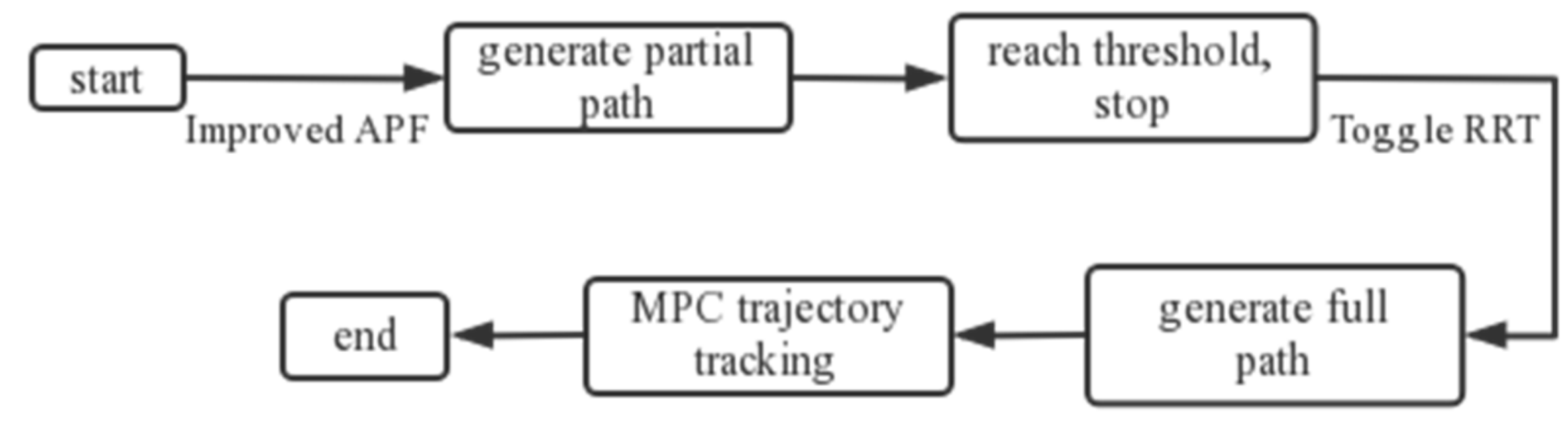
This paper uses the advantages of the RRT algorithm as a supplement to make up for the shortcomings of the improved artificial potential field method to plan an optimal path and use the MPC trajectory tracking comparison to verify whether the path satisfies the vehicle motion. The algorithm combined with the flowchart is shown in Figure 6, and the specific steps are as follows:
Step 1. Firstly, the improved artificial potential field method is used to plan the path from the initial position. Under the interaction of the gravitational field and the repulsion field, the vehicle is allowed to move towards the target direction while avoiding obstacles.
Step 2. The distance threshold is set and the distance between the position of the vehicle and the target every time it travels in the environment is calculated. When the distance is less than or equal to the threshold, the repulsion and gravitational force of the vehicle position are set at zero.
Step 3. When the distance between the path and the obstacle is equal to the threshold, the RRT algorithm is automatically switched to plan the remaining path. Finally, the target needs to be found and a new path needs to be planned.
Step 4. MPC is used to track the trajectory to verify whether the new path conforms to the vehicle’s motion.
3. Results
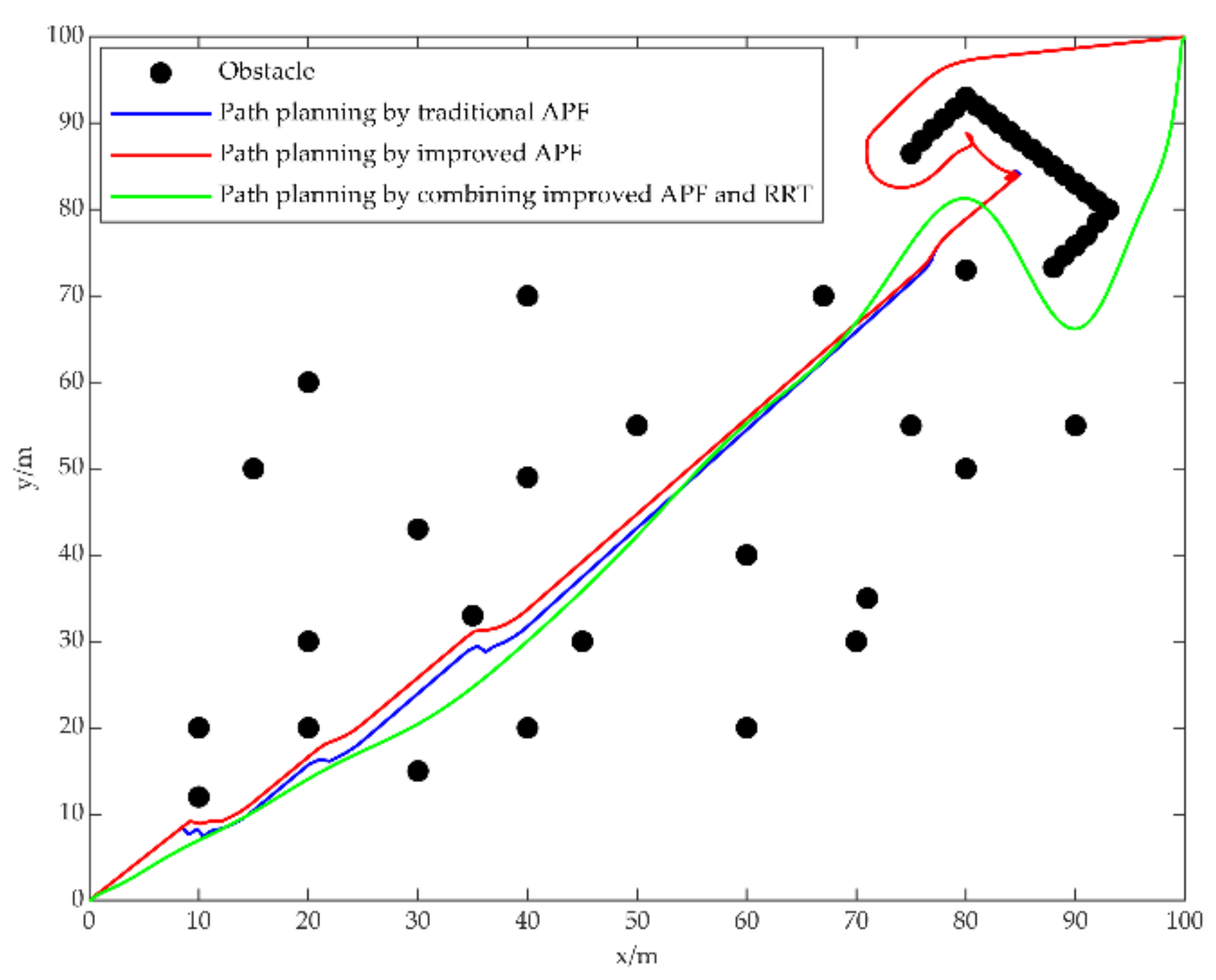
This simulation sets up a complex environment to compare the two methods. In Matlab, [0 0] was set as the initial position, [100 100] as the target position, and the coordinates of multiple static obstacles were set. At the same time, the key parameters are analyzed and selected to ensure the passage of vehicles. Specific parameter settings are shown in Table 1.
3.1. Experiment 1: Setting up Multiple Obstacles in the Environment
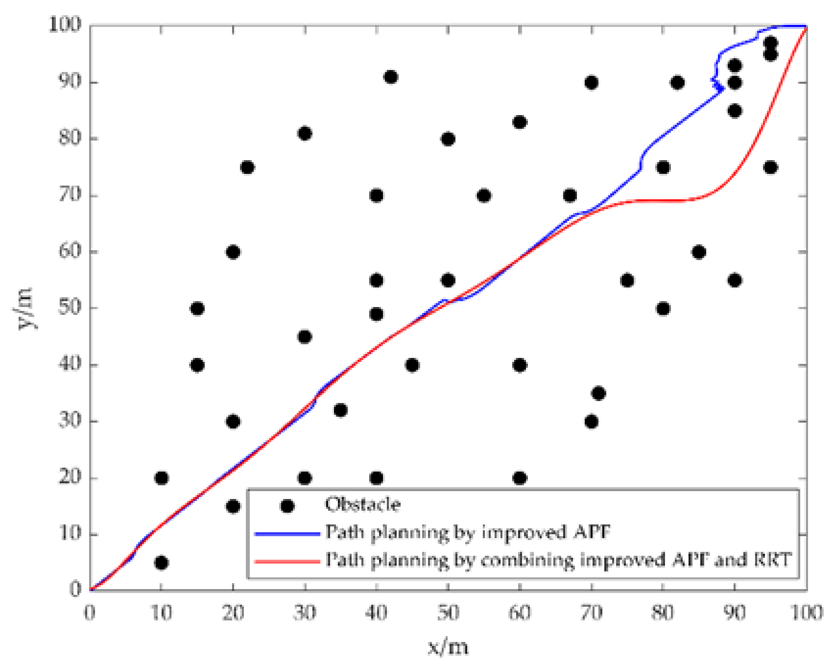
Figure 7 shows the comparison of the two path planning methods. Multiple obstacles are placed in the environment and the target is within the influence range of the obstacle’s repulsion field. It can be seen from the figure that the path planned by the artificial potential field method with the improved repulsion function oscillates near the obstacle closer to the target, but the path finally reaches the target.
The path planned by the combination of the RRT algorithm and the artificial potential field method with improved repulsion function, through the setting of the threshold, the RRT algorithm is switched in time before approaching the last obstacle and finally the target is reached. It can be seen that the path planned by this method is very smooth and without oscillation.
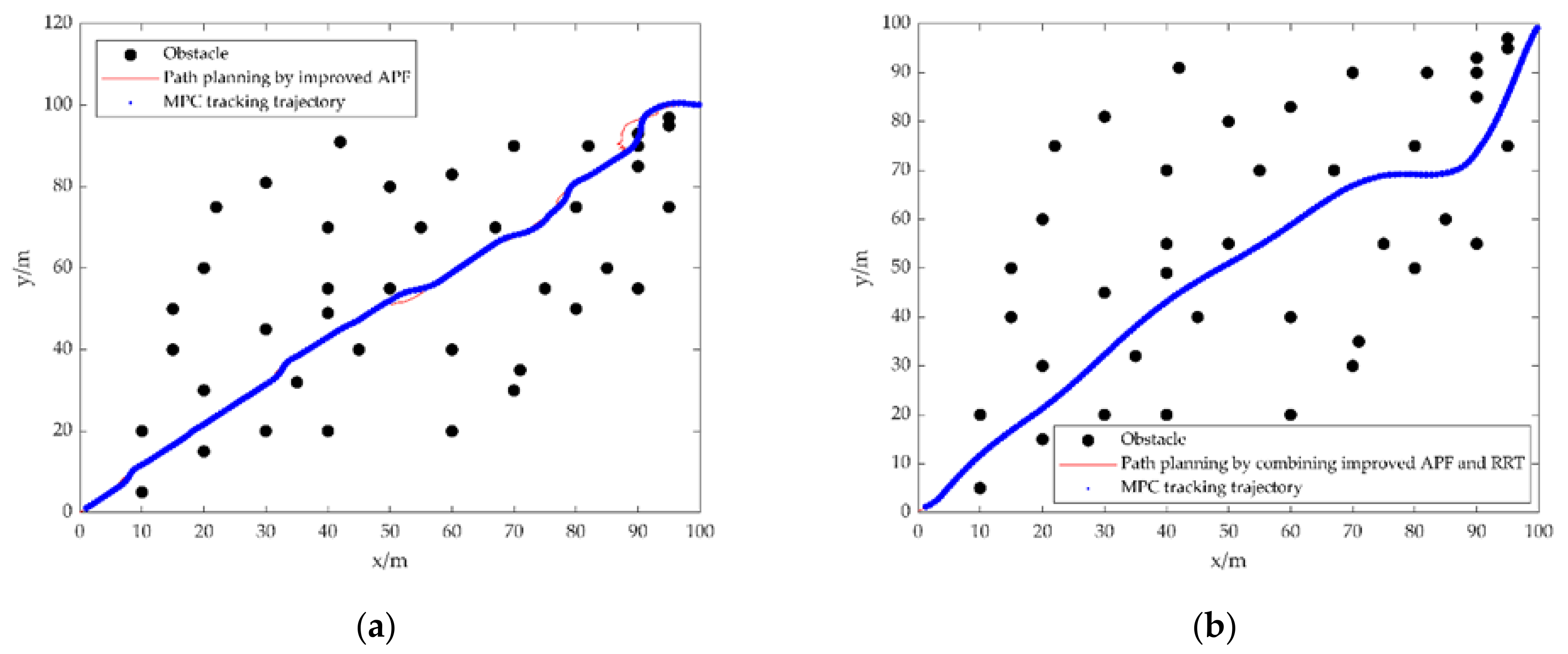
Figure 8 shows that the two paths are tracked by the MPC tracking trajectory method to verify whether the paths planned by the two methods conform to the vehicle motion. The coordinates of the obstacles in Figure 8a remain unchanged. When using MPC to track the path planned by the artificial potential field method with improved repulsion function, the tracking starts from the starting point, and the tracking error is large at the turning position and the oscillating position of the path. When tracking a path where oscillations occur, the vehicle cannot follow the reference path and goes straight through the centre of the obstacle, which does not conform to the motion of the vehicle.
As shown in Figure 8b, the MPC tracking trajectory method is used to track the path planned by the combination of the RRT algorithm and the artificial potential field method with the improved repulsion function. It can be seen from the figure that the red path has been completely covered by the MPC tracking track points and that the turn of the path can be precisely tracked until the target is reached. Therefore, the path planned by this method is easier to track and more in line with the vehicle motion.
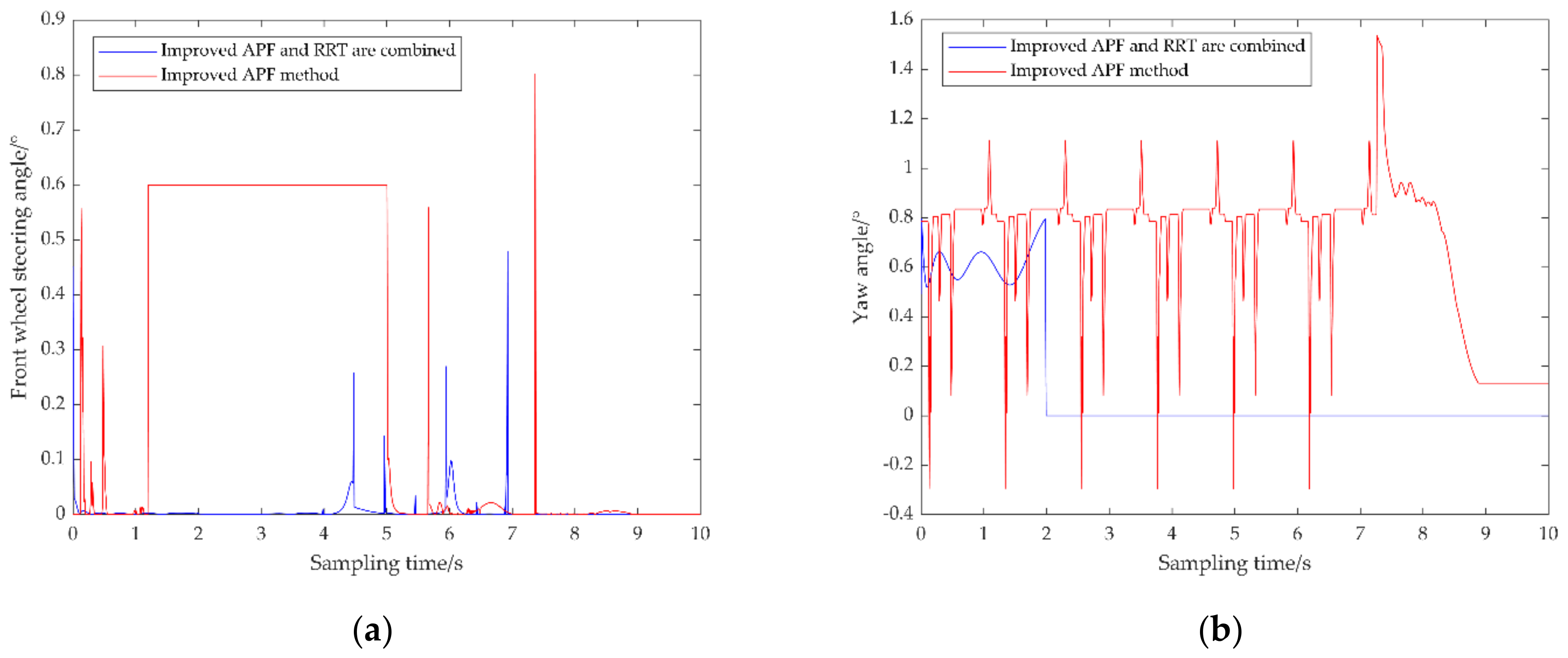
Figure 9 shows the comparison of the front wheel steering angle and yaw angle generated by MPC tracking two paths under the same speed. Figure 9a When the sampling time is between 5 s and 15 s, the front wheel rotation angle generated by the path planned by the artificial potential field method of vehicle tracking the improved repulsion function fluctuates greatly and the result is within the controllable range. At the same time, the fluctuation of the path planned by the combination of the RRT algorithm and the artificial potential field method with improved repulsion function is significantly smaller, indicating that the vehicle is more stable when tracking the path planned by this method.
Figure 9b When the sampling time is between 10 s and 15 s, the yaw angle generated by the vehicle tracking the two paths fluctuates greatly and the results are all within the controllable range. Similarly, the path planned by the RRT algorithm combined with the artificial potential field method with improved repulsion function has significantly less fluctuation, which means that the vehicle is more accurate in tracking the path planned by this method.
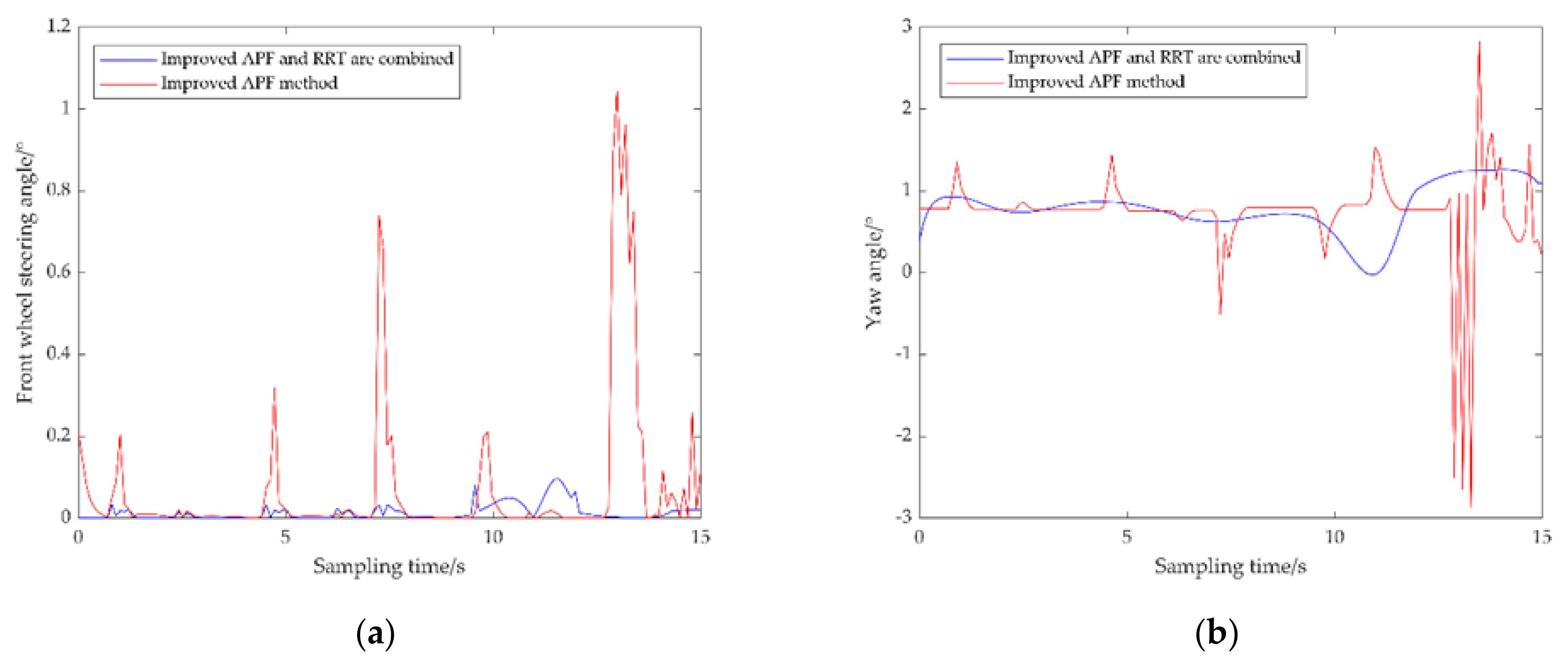
3.2. Experiment 2: Set up U-Shaped Obstacles in the Environment
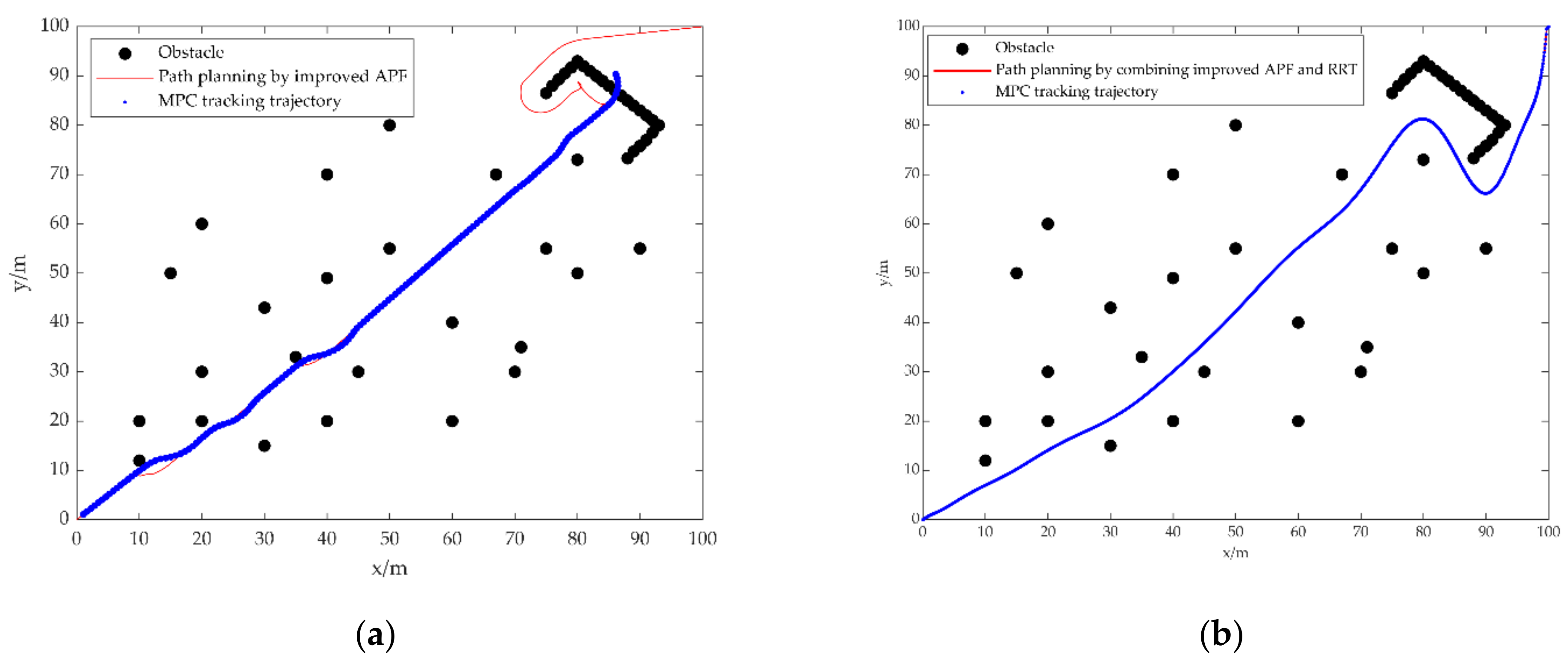
The difference between Figure 7 and Figure 10 is that U-shaped obstacles are set near the target and the positions of the obstacles are not on the same line with the target and the target is within the influence range of the obstacle repulsion field. The path is also planned from the starting point. For a U-shaped obstacles environment, the blue path represents the path planned by the traditional artificial potential field method. When passing through the U-shaped obstacle, the path oscillates and falls into the trap of local minima. Although the path planned by the artificial potential field method with improved repulsion function escapes the U-trap and solves the local minimal value problem, the path planned by the artificial potential field method with improved repulsion function oscillates more violently when approaching obstacles near the target than in the multiple obstacles environment. The path planned by combining the RRT algorithm and the artificial potential field method with the improved repulsion function can still effectively avoid U-shaped obstacles and eliminate oscillations to reach the target.
The coordinates of the obstacles in Figure 11a remain unchanged. When the MPC method is applied from the starting point to track the path planned using the artificial potential field method with improved repulsive function, the vehicle generates too much error in tracking the reference path because there are multiple oscillations in the path. The trajectory shown by the tracking has large errors in the steering position and oscillation position of the path. When tracking the path where the oscillation occurs, the trajectory generated by MPC tracking goes directly through the obstacle. After passing through the obstacle, the vehicle stops moving forward and cannot continue to track the trajectory. It can be seen that this path does not satisfy the vehicle motion.
Figure 11b Using MPC to track the path planned by the combination of the RRT algorithm and the artificial potential field method with improved repulsion function. It can be seen from the figure that the red path has been completely covered by the MPC tracking track points, while at the turn of the path it can still be accurately tracked until the target is reached. The path planned by this method is easier to track and more in line with the vehicle movement.
Figure 12a When the sampling time is between 0 s and 8 s, the front wheel steering angle generated by the path planned by the artificial potential field method of MPC tracking the improved repulsion function fluctuates greatly during this time period and the result is also within the controllable range. At the same time, the path planned by the combination of the MPC tracking RRT algorithm and the artificial potential field method with improved repulsion function has less fluctuation, which means that the vehicle is more stable when tracking the path planned by this method.
Figure 12b The yaw angle generated by the path planned by the artificial potential field method of MPC tracking the improved repulsion function fluctuates greatly between 0 s and 9 s. In the whole sampling period, the overall fluctuation of the yaw angle produced by the path planned by the combination of the RRT algorithm and the artificial potential field method with improved repulsion function is small. It shows that the path planned by this method is more accurate when vehicle tracking is performed.
By simulating in two different environments, it can be seen from the path planning simulation comparison that the artificial potential field method with a single improved repulsion function can avoid obstacles and reach the target position in two complex environments. Although the local minima defect of the traditional artificial potential field method is solved, the path oscillation cannot be avoided, and the planned path of this method does not conform to the vehicle motion and the efficiency is low, which is not the optimal path. Combining the RRT algorithm with the improved artificial potential field method, no matter how complex the environment is, it can always plan an optimal path that conforms to the motion of the vehicle without oscillation.
From the comparative analysis of the trajectory tracking simulation, it can be seen that for the environment with multiple obstacles and U-shaped obstacles, the fluctuation range of the front wheel steering angle generated by the path planned by the method proposed in this paper is 0~0.15° and 0~0.5°, respectively, and the resulting yaw angle fluctuations range from 0~1.5° and 0~0.8°. The fluctuation range of the front wheel steering angle generated by the path planned by the vehicle tracking single improved artificial potential field method is 0~1.2° and 0~0.9°, and the generated yaw angle fluctuation range is −3~+3° and −0.4~1.6°. Although the simulation results of the two experiments are within the specified range, the path planned by the combination of the tracking RRT algorithm and the artificial potential field method with the improved repulsion function generates the smallest fluctuation range of the front wheel steering angle and the yaw angle. This further proves that the path planned by the combination of the vehicle tracking RRT algorithm and the artificial potential field method with improved repulsion function is more stable and the path conforms to the vehicle motion.
4. Conclusions
Aiming at the problem that the path planned by the improved artificial potential field method oscillates, this paper proposes a path planning method for unmanned vehicles based on the combination of the RRT algorithm and the improved artificial potential field method. The sampling function and obstacle avoidance method of the RRT algorithm can effectively solve the problem of path oscillation. When the path planned by the improved artificial potential field method oscillates, the RRT algorithm is switched in time to complete the remaining path planning. The planned path is smoothed and the MPC method is used to control the vehicle to track the path. Matlab simulation experiments show that in a complex environment, the path planned by this method does not oscillate and is an optimal path, and the vehicle can track the path stably, satisfying vehicle movement. At the same time, the smooth and non-oscillating path can reduce the wear of the tires during the driving process of the vehicle to a certain extent and improve the driving safety.
Author Contributions
Conceptualization, H.M., W.P. and Q.Z.; methodology, H.M. and W.P.; software, H.M.; validation, H.M., W.P. and Q.Z.; formal analysis, H.M., W.P. and Q.Z.; investigation, H.M. and W.P.; resources, H.M.; data curation, H.M., W.P. and Q.Z.; writing—original draft preparation, H.M.; writing—review and editing, W.P.; visualization, H.M. and W.P.; supervision, W.P. and Q.Z.; project administration, W.P. and Q.Z.; funding acquisition, W.P. All authors have read and agreed to the published version of the manuscript.
Funding
This research was funded by Shandong Provincial Natural Science Foundation, grant number ZR2020QF059, ZR2021MF131; Foundation of State Key Laboratory of Automotive Simulation and Control, grant number 20181119.
Institutional Review Board Statement
Not applicable.
Informed Consent Statement
Not applicable.
Data Availability Statement
Not applicable.
Conflicts of Interest
The authors declare that they have no conflict of interest.
References
- Wang, X.D.; Luo, X.; Han, B.L.; Chen, Y.H.; Liang, G.H.; Zheng, K.L. Collision-Free Path Planning Method for Robots Based on an Improved Rapidly-Exploring Random Tree Algorithm. Appl. Sci. 2020, 10, 1381. [Google Scholar] [CrossRef] [Green Version]
- Wu, Z.P.; Meng, Z.J.; Zhao, W.L.; Wu, Z. Fast-RRT: A RRT-Based Optimal Path Finding Method. Appl. Sci. 2021, 11, 11777. [Google Scholar] [CrossRef]
- Yang, S.M.; Lin, Y.A. Development of an Improved Rapidly Exploring Random Trees Algorithm for Static Obstacle Avoidance in Autonomous Vehicles. Sensors 2021, 21, 2244. [Google Scholar] [CrossRef] [PubMed]
- Yang, S.M.; Yi, J.H.; Sun, R.T.; Bai, H.A. Path Planning of a Mechanical Arm Based on an Improved Artificial Potential Field and a Rapid Expansion Random Tree Hybrid Algorithm. Algorithms 2021, 14, 321. [Google Scholar]
- Feng, J.; Zhang, W. An Efficient RRT Algorithm for Motion Planning of Live-Line Maintenance Robots. Appl. Sci. 2021, 11, 10773. [Google Scholar] [CrossRef]
- Wen, N.F.; Zhang, R.B.; Wu, J.W.; Liu, G.Q. Online planning for relative optimal and safe paths for USVs using a dual sampling domain reduction-based RRT* method. Int. J. Mach. Learn. Cybern. 2020, 11, 2665–2687. [Google Scholar] [CrossRef]
- Qi, J.; Yang, H.; Sun, H.X. MOD-RRT*: A Sampling-based algorithm for robot path planning in dynamic environment. IEEE Trans. Ind. Electron. 2020, 68, 7244–7251. [Google Scholar] [CrossRef]
- Ge, Q.; Li, A.; Li, S.; Du, H.; Huang, X.; Niu, C. Improved Bidirectional RRT Path Planning Method for Smart Vehicle. Math. Probl. Eng. 2021, 2021, 6669728. [Google Scholar] [CrossRef]
- Zhang, X.; Zhu, T.; Xu, Y.; Liu, H.; Liu, F. Local Path Planning of the Autonomous Vehicle Based on Adaptive Improved RRT Algorithm in Certain Lane Environments. Actuators 2020, 11, 109. [Google Scholar] [CrossRef]
- Adamowicz, M.; Ambroziak, L.; Kondratiuk, M. Efficient Non-Odometry Method for Environment Mapping and Localisation of Mobile Robots. Acta Mech. Autom. 2021, 15, 24–29. [Google Scholar] [CrossRef]
- An, H.; Hu, J.; Lou, P. Obstacle Avoidance Path Planning Based on Improved APF and RRT. In Proceedings of the 2021 4th International Conference on Advanced Electronic Materials, Computers and Software Engineering (AEMCSE), Changsha, China, 26–28 March 2021; pp. 1028–1032. [Google Scholar]
- Xu, J.; Tian, Z.; He, W.; Huang, Y. A Fast Path Planning Algorithm Fusing PRM and P-Bi-RRT. In Proceedings of the 2020 11th International Conference on Prognostics and System Health Management, Jinan, China, 23–25 October 2020; pp. 503–508. [Google Scholar]
- Yuan, C.; Weng, S.; Shen, J.; Chen, L.; He, Y.; Wang, T. Research on active collision avoidance algorithm for intelligent vehicle based on improved artificial potential field model. Int. J. Adv. Robot. Syst. 2020, 17, 1729881420911232. [Google Scholar] [CrossRef]
- Yi, Z.; Li, L.; Qu, X.; Hong, Y.; Mao, P.; Ran, B. Using artificial potential field theory for a cooperative control model in a connected and automated vehicles environment. Transp. Res. Rec. 2020, 2674, 1005–1018. [Google Scholar] [CrossRef]
- Chang, Z.Y.; Zhang, Z.W.; Deng, Q.; Li, Z.R. Route planning of intelligent bridge cranes based on an improved artificial potential field method. J. Intell. Fuzzy Syst. 2021, 41, 4369–4376. [Google Scholar] [CrossRef]
- Yu, W.Q.; Lu, Y.G. UAV 3D environment obstacle avoidance trajectory planning based on improved artificial potential field method. J. Phys. Conf. Ser. 2021, 1885, 022020. [Google Scholar] [CrossRef]
- Zhang, H.; Li, M.; Wu, Z. Path Planning Based on Improved Artificial Potential Field Method. In Proceedings of the 33rd Chinese Control and Decision Conference (CCDC), Kunming, China, 22–24 May 2021; pp. 4922–4925. [Google Scholar]
- Yan, Z.; Jiang, L.; Wu, D. A Path Planning Algorithm based on Artificial Potential Field Method and Ant Colony Algorithm. In Proceedings of the IEEE International Conference on Mechatronics and Automation (ICMA), Takamatsu, Japan, 08–11 August 2021; pp. 1454–1459. [Google Scholar]
- Abbas, N.A.F.; Alniemi, O.; Yonan, J.F. Hybridization of Artificial Potential Field and D* Algorithm for Mobile Robot of Path Planning in Dynamic Environment. In Electronic Systems and Intelligent Computing; Springer: Singapore, 2022; pp. 765–774. [Google Scholar]
- Das, M.S.; Sanyal, S.; Mandal, S. Navigation of Multiple Robots in Formative Manner in an Unknown Environment using Artificial Potential Field Based Path Planning Algorithm. Ain Shams Eng. J. 2022, 13, 101675. [Google Scholar] [CrossRef]
- Hwang, J.; Lee, J.; Park, C. Collision avoidance control for formation flying of multiple spacecraft using artificial potential field. Adv. Space Res. 2022, 69, 2197–2209. [Google Scholar] [CrossRef]
- Li, D.F.; Pan, Z.H.; Deng, H.B. Two-dimensional obstacle avoidance control algorithm for snake-like robot in water based on immersed boundary-lattice Boltzmann method and improved artificial potential field method. Trans. Inst. Meas. Control 2020, 42, 1840–1857. [Google Scholar] [CrossRef]
- Xiao, M.; Zuan, L.; Song, R.Y. Local path planning for unmanned surface vehicle with improved artificial potential field method. J. Phys. Conf. Ser. 2020, 1634, 12125. [Google Scholar] [CrossRef]
- Zha, M.; Wang, Z.W.; Feng, J.; Cao, X.L. Unmanned Vehicle Route Planning Based on Improved Artificial Potential Field Method. J. Phys. Conf. Ser. 2020, 1453, 012059. [Google Scholar] [CrossRef] [Green Version]
- Wu, H.; Zhang, Y.; Huang, L.; Zhang, J.; Luan, Z.; Zhao, W.; Chen, F. Research on vehicle obstacle avoidance path planning based on APF-PSO. J. Automob. Eng. 2022, 09544070221088364. [Google Scholar] [CrossRef]
- Tian, J.; Bei, S.; Li, B.; Hu, H.; Quan, Z.; Zhou, D.; Tang, H. Research on Active Obstacle Avoidance of Intelligent Vehicles Based on Improved Artificial Potential Field Method. World Electr. Veh. J. 2022, 13, 97. [Google Scholar] [CrossRef]
- Sang, H.; You, Y.; Sun, X.; Zhou, Y.; Liu, F. The hybrid path planning algorithm based on improved A* and artificial potential field for unmanned surface vehicle formations. Ocean Eng. 2021, 223, 108709. [Google Scholar] [CrossRef]
- Duhé, J.; Victor, S.; Melchior, P. Contributions on artificial potential field method for effective obstacle avoidance. Fract. Calc. Appl. Anal. 2021, 24, 421–446. [Google Scholar] [CrossRef]
- Feng, S.; Qian, Y.; Wang, Y. Collision avoidance method of autonomous vehicle based on improved artificial potential field algorithm. Proc. Inst. Mech. Eng. Part D J. Automob. Eng. 2021, 235, 3416–3430. [Google Scholar] [CrossRef]
- Zheyi, C.; Bing, X. AGV Path Planning Based on Improved Artificial Potential Field Method. In Proceedings of the IEEE International Conference on Power Electronics Computer Applications, Shenyang, China, 22–24 January 2021; pp. 32–37. [Google Scholar]
- Chen, Z.; Gao, Q.; Wang, X.; Liu, X. Local Path Planning of Intelligent Vehicle Based on Improved Artificial Potential Field. In Proceedings of the 3rd International Conference on Electronic Information and Communication Technology (ICEICT), Shenzhen, China, 13–15 November 2020; pp. 110–116. [Google Scholar]
- Deng, W.; Zhang, K.; Zhang, X.; Yu, F.; Lin, M.; Shang, S.; Guo, M. Improved Potential Field-Based Collision Avoidance Control for Autonomous Vehicles. In Proceedings of the WCX SAE World Congress Experience, Detroit, MI, USA, 21–23 April 2020. [Google Scholar]
- Jia, Y.; Qu, D.; Song, H.; Wang, T.; Zhao, Z. Car-following characteristics and model of connected autonomous vehicles based on safe potential field. Phys. A Stat. Mech. Its Appl. 2022, 586, 126502. [Google Scholar] [CrossRef]
- Sun, Z.; Sun, H.; Li, P.; Zou, J.; Zhuang, J.; Tan, G. An innovative distributed self-organizing control of unmanned surface vehicle swarm with collision avoidance. Ocean Eng. 2022, 254, 111342. [Google Scholar] [CrossRef]
- Wang, C.; Wang, Z.; Zhang, L.; Yu, H.; Cao, D. Post-Impact Motion Planning and Tracking Control for Autonomous Vehicles. Chin. J. Mech. Eng. 2022, 35, 54. [Google Scholar] [CrossRef]
- Wang, S.; Li, Z.; Wang, B.; Ma, J.; Yu, J. Velocity obstacle-based collision avoidance and motion planning framework for connected and automated vehicles. Transp. Res. Rec. 2022, 2676, 03611981211070286. [Google Scholar] [CrossRef]
- Wu, P.; Gao, F.; Li, K. Humanlike decision and motion planning for expressway lane changing based on artificial potential field. IEEE Access 2022, 10, 4359–4373. [Google Scholar] [CrossRef]
- Wang, S.; Lin, F.; Wang, T.; Zhao, Y.; Zang, L.; Deng, Y. Autonomous Vehicle Path Planning Based on Driver Characteristics Identification and Improved Artificial Potential Field. Actuators 2022, 11, 52. [Google Scholar] [CrossRef]
- Abdullah, Z.; Heerwan, P.M.; Zakaria, M.A.; Ishak, M.I. Investigation of the Combination of Kinematic Path Planning and Artificial Potential Field Path Planning with PI Controller for Autonomous Emergency Braking Pedestrian (AEB-P) System. In Enabling Industry 4.0 through Advances in Mechatronics; Springer: Singapore, 2022; pp. 285–297. [Google Scholar]
- Sakhnevych, A.; Arricale, V.M.; Bruschetta, M.; Censi, A.; Mion, E.; Picotti, E.; Frazzoli, E. Investigation on the model-based control performance in vehicle safety critical scenarios with varying tyre limits. Sensors 2021, 21, 5372. [Google Scholar] [CrossRef] [PubMed]
- Farroni, F.; Sakhnevych, A. Tire multiphysical modeling for the analysis of thermal and wear sensitivity on vehicle objective dynamics and racing performances. Simul. Model. Pract. Theory 2022, 117, 102517. [Google Scholar] [CrossRef]
- Sakhnevych, A. Multiphysical MF-based tyre modelling and parametrisation for vehicle setup and control strategies optimisation. Veh. Syst. Dyn. 2021, 1–22. [Google Scholar] [CrossRef]
- Vu, T.M.; Moezzi, R.; Cyrus, J.; Hlava, J.; Petru, M. Autonomous Vehicle Tracking Based on Non-Linear Model Predictive Control Approach. In Applications of Computational Science in Artificial Intelligence; IGI Global: Hershey, PA, USA, 2022; pp. 74–131. [Google Scholar]
- Pang, H.; Liu, N.; Hu, C.; Xu, Z. A practical trajectory tracking control of autonomous vehicles using linear time-varying MPC method. Proc. Inst. Mech. Eng. Part D J. Automob. Eng. 2022, 236, 709–723. [Google Scholar] [CrossRef]
- Jeong, Y.; Yim, S. Model Predictive Control-Based Integrated Path Tracking and Velocity Control for Autonomous Vehicle with Four-Wheel Independent Steering and Driving. Electronics 2021, 10, 2812. [Google Scholar] [CrossRef]
- Li, S.; Wang, X.; Cui, G.; Lu, X.; Zhang, B. Yaw and lateral stability control based on predicted trend of stable state of the vehicle. Veh. Syst. Dyn. 2022, 1–17. [Google Scholar] [CrossRef]
- Xu, J.; Zhang, B.; Zhu, X.; Su, Y. Linear Time-Varying MPC Vehicle Trajectory Tracking Controller Considering Driving Road Surface Factors. In Proceedings of the 2021 International Conference on Control Science and Electric Power Systems (CSEPS), Shanghai, China, 28–30 May 2021; pp. 83–88. [Google Scholar]
- Liu, Z.; Ye, X.; Qian, T.; Yu, L. Research on Unmanned Vehicle Trajectory Tracking Control Strategy Based on Model Predictive Control. In Proceedings of the MEMAT 2022 2nd International Conference on Mechanical Engineering, Intelligent Manufacturing and Automation Technology, Guilin, China, 7–9 January 2022; pp. 1–5. [Google Scholar]
- Zhou, S. Research on Path Planning of Wheeled Robots Based on Improved A* Algorithm and Artificial Potential Field Method. Master’s Thesis, Taiyuan University of Technology, Taiyuan, China, 2021. [Google Scholar] [CrossRef]
- Wen, Q. Research on the Path Planning Method of Unmanned Vehicles Based on RRT. Master’s Thesis, Northeastern University, Shenyang, China, 2019. [Google Scholar] [CrossRef]
- Zhang, C.Y.; Chu, D.F.; Liu, S.D.; Deng, Z.J.; Wu, C.Z. Trajectory Planning and Tracking for Autonomous Vehicle Based on State Lattice and Model Predictive Control. IEEE Intell. Transp. Syst. Mag. 2019, 11, 29–40. [Google Scholar] [CrossRef]
- Wu, H.D.; Si, Z.L.; Li, Z.H. Trajectory Tracking Control for Four-Wheel Independent Drive Intelligent Vehicle Based on Model Predictive Control. IEEE Access 2020, 8, 73071–73081. [Google Scholar] [CrossRef]
- Fan, X.B.; Peng, Y.X.; Zhong, C. Tracking Control Based on Adaptive MPC. J. Fuzhou Univ. Nat. Sci. Ed. 2021, 49, 500–507. [Google Scholar]
Figure 1.
Force analysis of moving vehicle in artificial potential field.

Figure 2.
Force analysis of moving vehicle in improved artificial potential field.

Figure 3.
Schematic diagram of RRT algorithm.

Figure 4.
Collision detection schematic diagram of RRT algorithm.

Figure 5.
Vehicle dynamics model.

Figure 6.
Algorithm combination process.

Figure 7.
The path planned by the two methods.

Figure 8.
(a) MPC tracks the trajectory planned by the improved APF method; (b) MPC tracks the trajectory planned by the combination of the improved APF method and the RRT algorithm.
Figure 8.
(a) MPC tracks the trajectory planned by the improved APF method; (b) MPC tracks the trajectory planned by the combination of the improved APF method and the RRT algorithm.

Figure 9.
(a) Front–wheel steering angle generated by MPC tracking trajectory; (b) Yaw angle gen–erated by MPC tracking trajectory.
Figure 9.
(a) Front–wheel steering angle generated by MPC tracking trajectory; (b) Yaw angle gen–erated by MPC tracking trajectory.

Figure 10.
The path planned by the three methods.

Figure 11.
(a) MPC tracks the trajectory planned by the improved APF method; (b) MPC tracks the trajectory planned by the combination of the improved APF method and the RRT algorithm.
Figure 11.
(a) MPC tracks the trajectory planned by the improved APF method; (b) MPC tracks the trajectory planned by the combination of the improved APF method and the RRT algorithm.

Figure 12.
(a) Front–wheel steering angle generated by MPC tracking trajectory; (b) Yaw angle generated by MPC tracking trajectory.
Figure 12.
(a) Front–wheel steering angle generated by MPC tracking trajectory; (b) Yaw angle generated by MPC tracking trajectory.


Table 1.
Experimental data.
| Variable Symbol | Name and Unit | Numerical Value |
|---|---|---|
| Gravity gain coefficient | 95 | |
| Repulsion gain coefficient | 100 | |
| Repulsion influence range/m | 4 | |
| thr | Distance threshold/m | 0.5 |
| APF_ste | Vehicle forward length/m | 1 |
| RRT_ste | Tree growth step/m | 1 |
| Prediction time domain | 60 | |
| Control time domain | 30 |
Publisher’s Note: MDPI stays neutral with regard to jurisdictional claims in published maps and institutional affiliations. |
© 2022 by the authors. Licensee MDPI, Basel, Switzerland. This article is an open access article distributed under the terms and conditions of the Creative Commons Attribution (CC BY) license (https://creativecommons.org/licenses/by/4.0/).
Share and Cite
MDPI and ACS Style
Ma, H.; Pei, W.; Zhang, Q. Research on Path Planning Algorithm for Driverless Vehicles. Mathematics 2022, 10, 2555. https://0-doi-org.brum.beds.ac.uk/10.3390/math10152555
AMA Style
Ma H, Pei W, Zhang Q. Research on Path Planning Algorithm for Driverless Vehicles. Mathematics. 2022; 10(15):2555. https://0-doi-org.brum.beds.ac.uk/10.3390/math10152555
Chicago/Turabian StyleMa, Hao, Wenhui Pei, and Qi Zhang. 2022. "Research on Path Planning Algorithm for Driverless Vehicles" Mathematics 10, no. 15: 2555. https://0-doi-org.brum.beds.ac.uk/10.3390/math10152555
Note that from the first issue of 2016, this journal uses article numbers instead of page numbers. See further details here.