

Free–Free Beam Resting on Tensionless Elastic Foundation Subjected to Patch Load


Interdisciplinary Research Center for Construction and Building Materials, King Fahd University of Petroleum and Minerals, Dhahran 31261, Saudi Arabia
*
Author to whom correspondence should be addressed.
Mathematics 2022, 10(18), 3271; https://0-doi-org.brum.beds.ac.uk/10.3390/math10183271
Submission received: 4 August 2022
/
Revised: 2 September 2022
/
Accepted: 3 September 2022
/
Published: 9 September 2022
(This article belongs to the Special Issue Advanced Numerical Methods in Computational Solid Mechanics)
Abstract
:Despite the popularity of a completely free beam resting on a tensionless foundation in the construction industry, the existing bending analysis solutions are limited to certain types of loads (mostly point and uniformly distributed loads); these are also quite complex for practicing engineers to handle. To overcome the associated complexity, a simple iterative procedure is developed in this study, which uses the Ritz method for the bending analysis of a free–free beam on a tensionless foundation subjected to a patched load. The Ritz method formulation is first presented with polynomials being used to approximate the beam deflection with unknown constants to be determined through minimization of the potential energy. To account for the tensionless action, the subgrade reaction is set to zero when the deflection is negative. The non-zero subgrade reaction zone is defined by where the coefficients and are to be determined iteratively. A numerical example is presented to illustrate the applicability of the proposed procedure for symmetrical and asymmetrical problems. The obtained results show high negative deflection, which proves the occurrence of separation between the beam and the supporting tensionless foundation. This location of negative deflection is called the lifted zone, while the point that separates between the negative and positive deflection is called the lift-off point. A parametric study is then performed to study the effect of the amount of load, stiffness of the beam, and the subgrade reaction on the length of the lifted zone. The results of the parametric study indicate that for the same beam stiffness to subgrade reaction modulus ratio (), the lift-off point remains the same and beams with lower stiffnesses or higher loads deflect more.
Keywords:
tensionless foundation; elastic foundation; Winkler foundation; beam bending; Ritz method; energy methodMSC:
74G651. Introduction
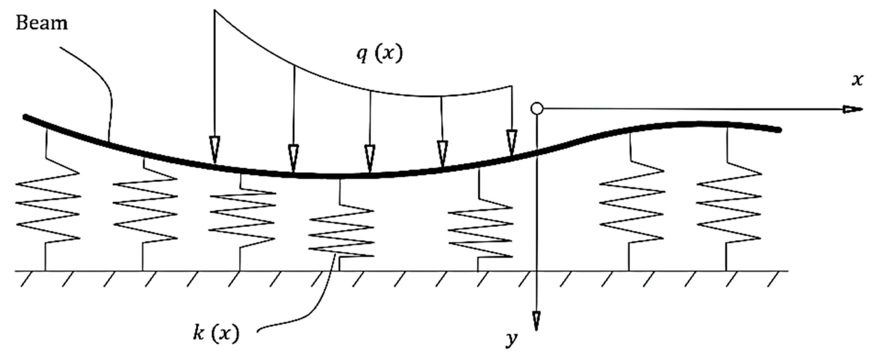
The concept of “beam on elastic foundation” is widely adopted in different engineering disciplines, including foundations of civil engineering structures [1,2] and spreader beams in load-bearing construction [3,4]. The commonly adopted Winkler model, which assumes the subgrade reaction as a set of closely spaced independent springs (Figure 1), leads to satisfactory results if applied to a case where the elastic foundation can provide both: tension and compression resistance or the springs are all under compression action. In contrast, in the cases where some of the springs are under tension and the elastic foundation has no tension resistance (soil for example), unsatisfactory (and sometimes misleading) results are possible. A typical example of this is partially loaded free–free beam resting on a soil bed where the ends of the beam tend to separate and lift from the soil. The obvious remedy to this problem is to ignore the stiffness of the springs under tension but their priori unknown locations are the main source of the complexity of the problem.
Tensionless foundations, which consider the stiffness of the compressed springs only, have attracted the research community over the last three decades. The published studies in this topic can generally be grouped into three different categories, each with its own challenges and applications. These categories are the nature of loading, the type of foundation model, and the beam geometry (finite/infinite). The nature of loading discussed includes static point loads (with and without distributed loads) [5,6,7,8,9,10] and also moving loads [11,12]. The applications of these types of loads were also discussed in these studies [5,6,7,8,9,10,11,12], such as the static point load can be applied to columns on strip foundations and moving point load can be applied to wheel load in pavements and railways. The types of foundation models addressed include the Winkler model [1,2], the two-parameter foundation model [13,14,15,16,17,18], the Reissner foundation [19], the elastic-plastic foundation [20], and others [21,22]. For each type of foundation model, a different sort of challenge presents itself. For instance, the two-parameter foundation model [13,14,15,16,17,18] considers the interaction of horizontal springs in addition to the vertical ones, which add a second order derivative term to the governing differential equation as compared to that of the Winkler model. However, depending on the application considered, the appropriate type of foundation model can be selected. In this study, the Winkler model has been selected because it gives satisfactory results for cases of building foundations [1,2] and spreader beams in load-bearing construction [3,4]. Furthermore, the beam geometry is either finite [6,7,9] or infinite [8,10,11,17]. The infinite beam can be defined as a beam where the effect of loading (e.g., deflection, shear force and bending moment) vanishes before the end of the beam—unlike the finite beam where the effect of loading can be seen all over the beam length. From these definitions, it is clear that instead of four boundary conditions for the finite beam problem, they can be reduced to two for the infinite beam, which eases the problem. However, selection of either finite or infinite beam requires understanding the physics of the problem considered. If railways or pipelines are considered, the obvious choice is an infinite beam; however, in the case of shallow foundations in buildings and spreader beams [3,4], one has to choose a finite beam and find an appropriate method that yields a solution satisfying all the four boundary conditions. The three categories mentioned in this paragraph are in many cases overlapping, such as considering point load on a finite beam resting on an elastic foundation with different foundation models.
The methods of analysis employed to tackle the considered problem include energy methods [23,24], numerical methods [13,25,26,27], and the superposition principle [28]. The energy methods yield approximate solutions and their accuracy depends on the appropriate selection of the function that describes the deformed shape of the beam. However, the numerical methods are generally mesh dependent and the accuracy can be improved by refining the mesh. One of the key differences between energy and numerical methods is the continuity of the solution. The obtained solution using energy methods is usually continuous (in a functional form) while that of the numerical methods is a discrete one. Having the solution in a continuous form is of great importance for conducting parametric studies and this is one reason behind selecting the Ritz method, as one of the energy methods, in this study.
Furthermore, the studies considering tensionless foundations are not limited to beams; plates on tensionless foundations were discussed [29,30,31] (which are applied to slab-on-grade) and buried beams/pipelines [32,33] resting on tensionless foundations were also investigated due to their wide range of applications in oil and gas industries.
In summary, due to the challenges associated with each of the categories discussed in the aforementioned, there is no one generic solution that can be used to tackle all these categories such as solving a beam on elastic foundation regardless of the type of load, foundation model, and beam geometry. Thus, researchers have extensively studied this topic focusing on applications related to their fields of industry. The considered problem is no exemption: it treats the case of free ends finite beam resting on a tensionless Winkler foundation under the action of a patched load, which is rarely discussed in the literature. A finite beam is selected because either building foundations [1,2] or spreader beams in load-bearing construction [3,4] are generally short and the free ends boundary conditions are the most common in these applications as well. The concept of patched load is also mathematically more general as compared to distributed load because the latter can be visualized as a patched load over the entire length of the beam. This study also makes use of the capabilities of the Ritz method of handling free ends boundary conditions and providing the solution in a continuous form. The latter feature of continuous solution facilitates conducting a parametric study to investigate the influence of the involved parameters.
In this study, a simple iterative procedure is developed using the Ritz method for bending analysis of a completely free beam on a tensionless elastic foundation. To account for the tensionless action, the subgrade reaction is set to zero at the locations of negative (upward) deflection. However, because these locations are priori unknown, the non-zero subgrade reaction zone is defined by where and are factors (less than unity) to be determined iteratively. For any given values of and , the Ritz method is utilized to solve the problem: deflection approximated with simple polynomials, multiplied by unknown constants, to be determined through minimization of the potential energy. Application of the proposed iterative procedure is illustrated through a numerical example that covers both symmetric and asymmetric patch loads. The obtained results show high negative deflection which proved the occurrence of separation between the beam and the supporting tensionless foundation. This location of negative deflection is called the lifted zone while the point that separates between the negative and positive deflection is called the lift-off point. The effect of the amount of patched load , the subgrade reaction modulus k, and the beam stiffness EI on the location of the lift-off point is also investigated through a parametric study. The investigation showed that for the same beam stiffness to subgrade reaction modulus ratio (), the lift-off point remains similar regardless of the amount of load, further the beam with lower stiffness or higher loads deflects more.
2. The Governing System of Equations
2.1. Tensionless Foundation
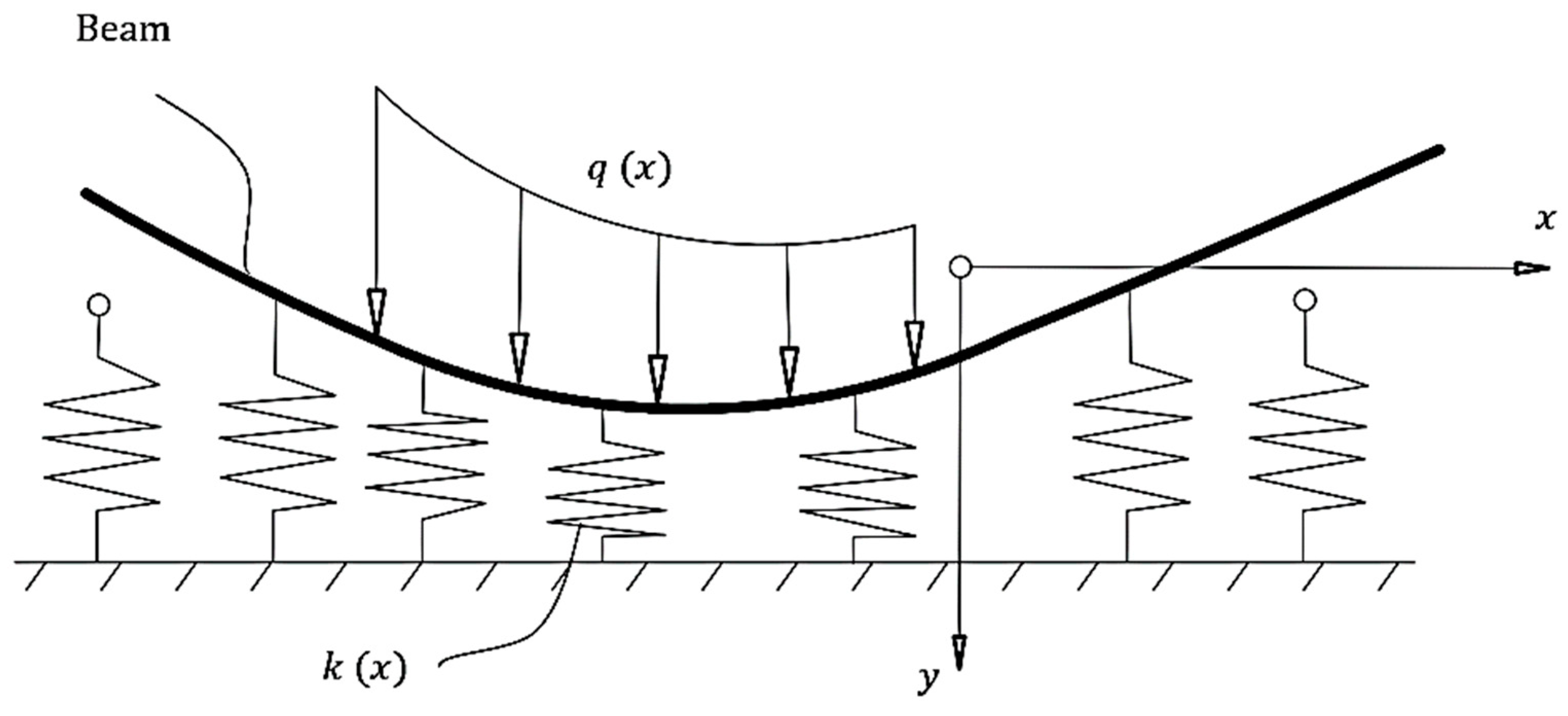
Consider a free–free beam resting on elastic Winkler foundation with subgrade reaction modulus and subjected to distributed patched load as shown in Figure 1. By definition of the Winkler model, the spring constants are equal in tension and compression. However, in the case of soil providing the elastic support, this definition is no longer accurate since the soil has no tension capacity. In this case, the springs near the ends of the free–free beam are more likely to be under tension and can separate from the beam as shown in Figure 2. The separation considerably affects the deformation behavior of the beam which results in different stress resultants.
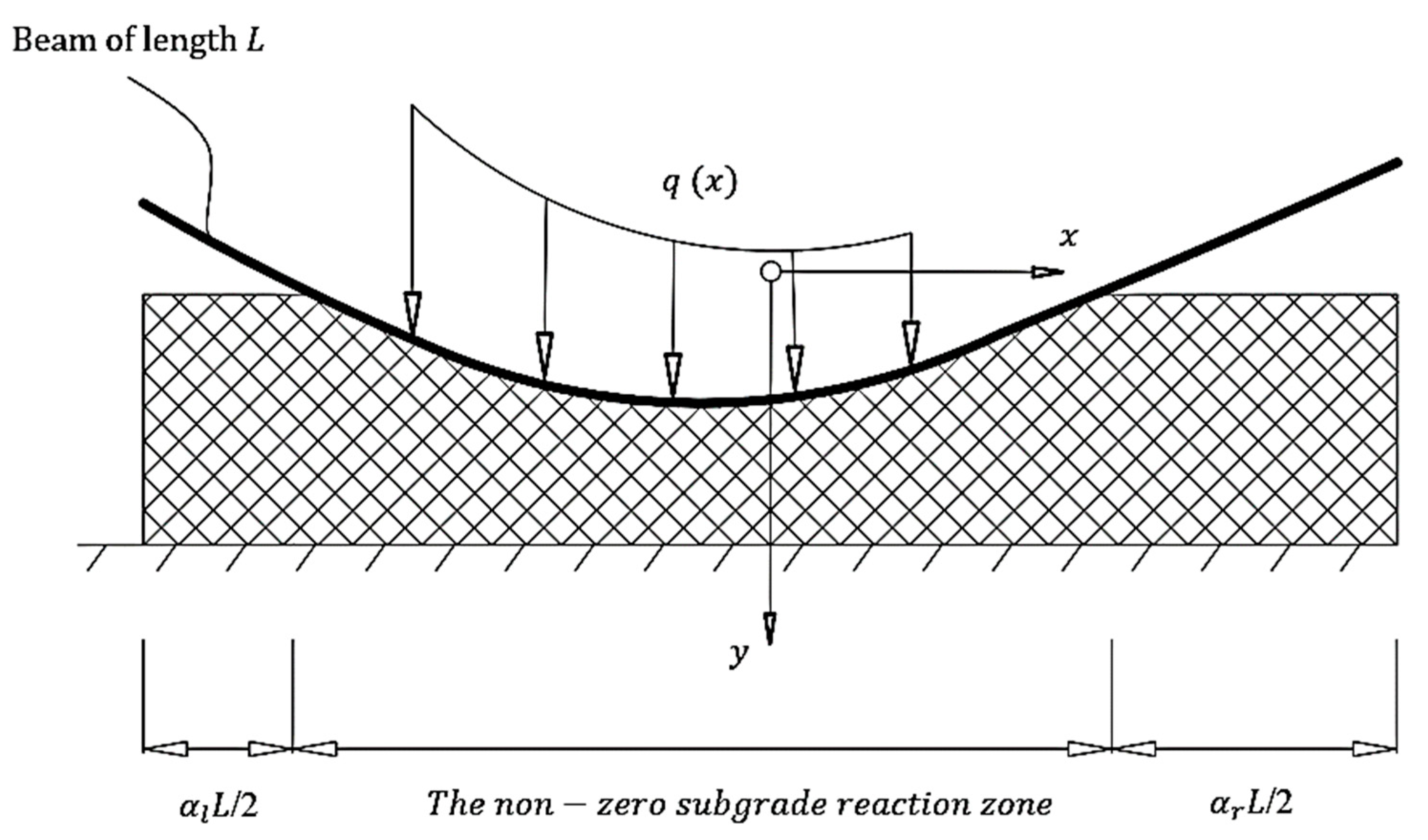
With the shown idealized deformation in Figure 2, it can be seen that the beam is lifted (separated) from the elastic spring supports at both ends. This can also be shown in a more simplified diagram as in Figure 3. Here the origin is located at the middle of the beam and the lifted zone from the left is represented by /2 and from the right by /2. In this case, the subgrade reaction can be expressed mathematically by Equation (1).
If the subgrade reaction modulus, beam material, beam geometry, and loads are all symmetrically distributed along the x-axis, the problem can be considered as a symmetric problem with
2.2. Ritz Method Formulation
The potential energy of a deforming beam of length () can simply be defined as the difference between the strain energy () stored in the beam during deformation and the work done by the external load , i.e.,
where the strain energy () is expressed by
and the work done () by the external force by
where is the deflection of the beam and is its flexural rigidity.
The first step in obtaining the solution using the Ritz method is to approximate the beam deflection by
where is a number of N functions satisfying the geometric (essential) boundary conditions and is a similar number of constants to be determined based on minimization of the potential energy.
Substitution of the assumed deflection (Equation (5)) into the potential energy expression yields
in which the summation is expressed by repeated indices as commonly known in the basics of indicial notations.
To obtain the unknown constants corresponding to the minimal potential energy, the following derivation is required.
which yields a system of linear algebraic equations expressed by
where and the elements of the other two matrices are expressed as follows
and
Solving the system of equations denoted by Equation (8) for the unknown constants and substituting them into Equation (5) yields the determination of the beam deflection expression. Other beam variables such as slope, bending moment, and shear force can be obtained thereafter by substitution into Equations (11) through (13), respectively [34,35].
However, before solving the governing system of Equations (Equation (8)), the approximating functions and the variable relating the non-zero subgrade reactions are all need to be known, which will be discussed in the following sections.
2.3. The Approximating Functions
It is noteworthy to draw the reader’s attention to the nature of boundary conditions that exist in beam problems, which can be classified into geometric and force boundary conditions. The geometric boundary condition is a condition on either the slope or deflection, while the force boundary is a condition on either the bending moment or shear force. The governing system of equations (Equation (8)) requires an approximating function satisfying only the geometric boundary conditions (deflection and/or slope) while the force boundary conditions can automatically be satisfied by increasing the number of polynomials. Fortunately, the considered free–free beam has boundary conditions in the form of , where M and V are the bending moment and shear force, respectively, as defined by Equations (12) and (13). These are considered to be force boundary conditions and there are no geometric ones involved, i.e., the beam is ideally free from deflection and slope restrictions. Consequently, this means that there are no boundary conditions to be considered for the approximating functions of the free–free beam and, therefore, the beam deflection can be approximated by the following polynomial expressions:
which can be applied for asymmetric problems. If the problem is symmetric, then the following expression is more efficient
It should be noted that a convergence study is needed to determine the appropriate number of polynomials (N).
2.4. The Zero Subgrade Reaction Zones
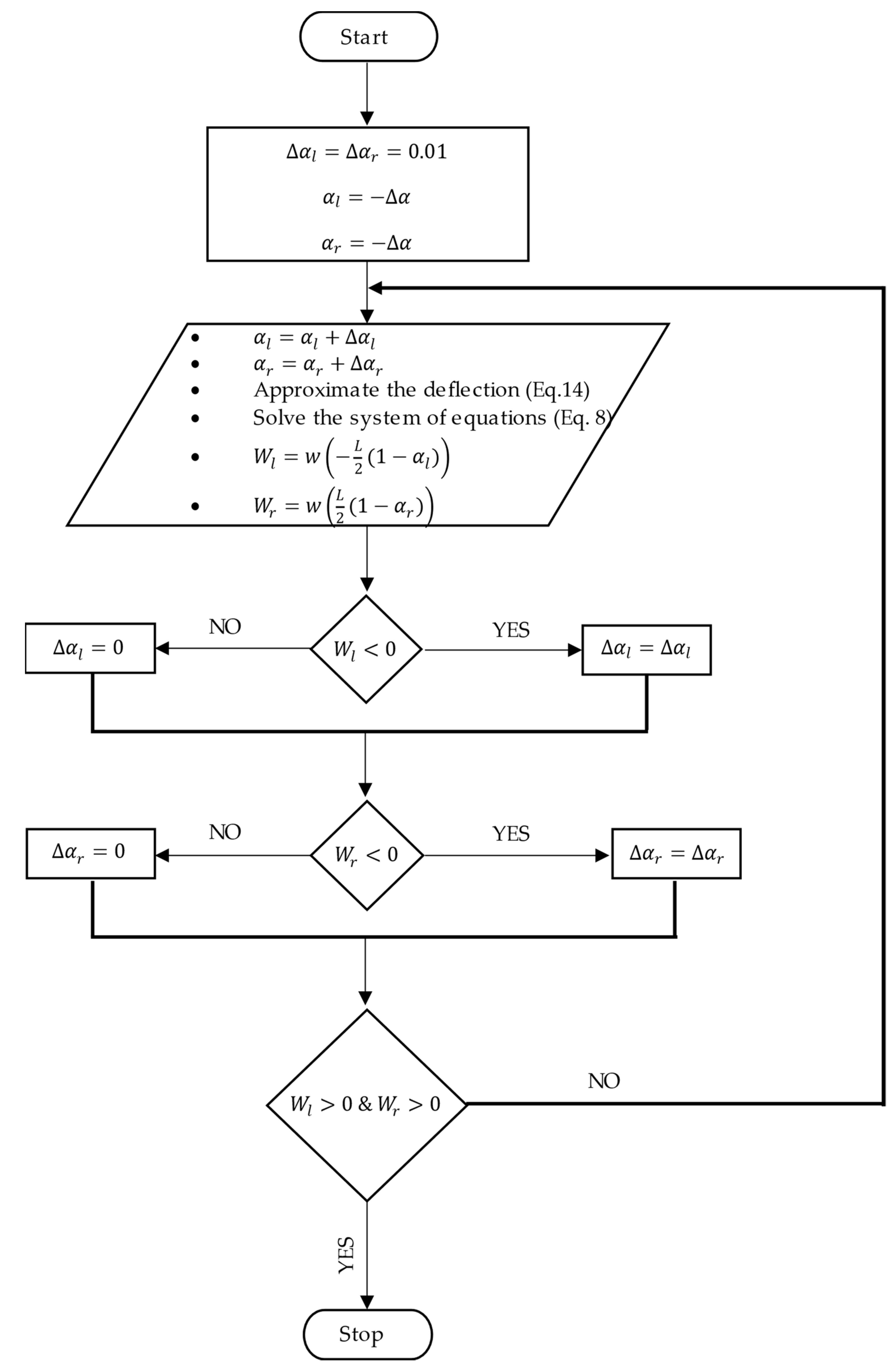
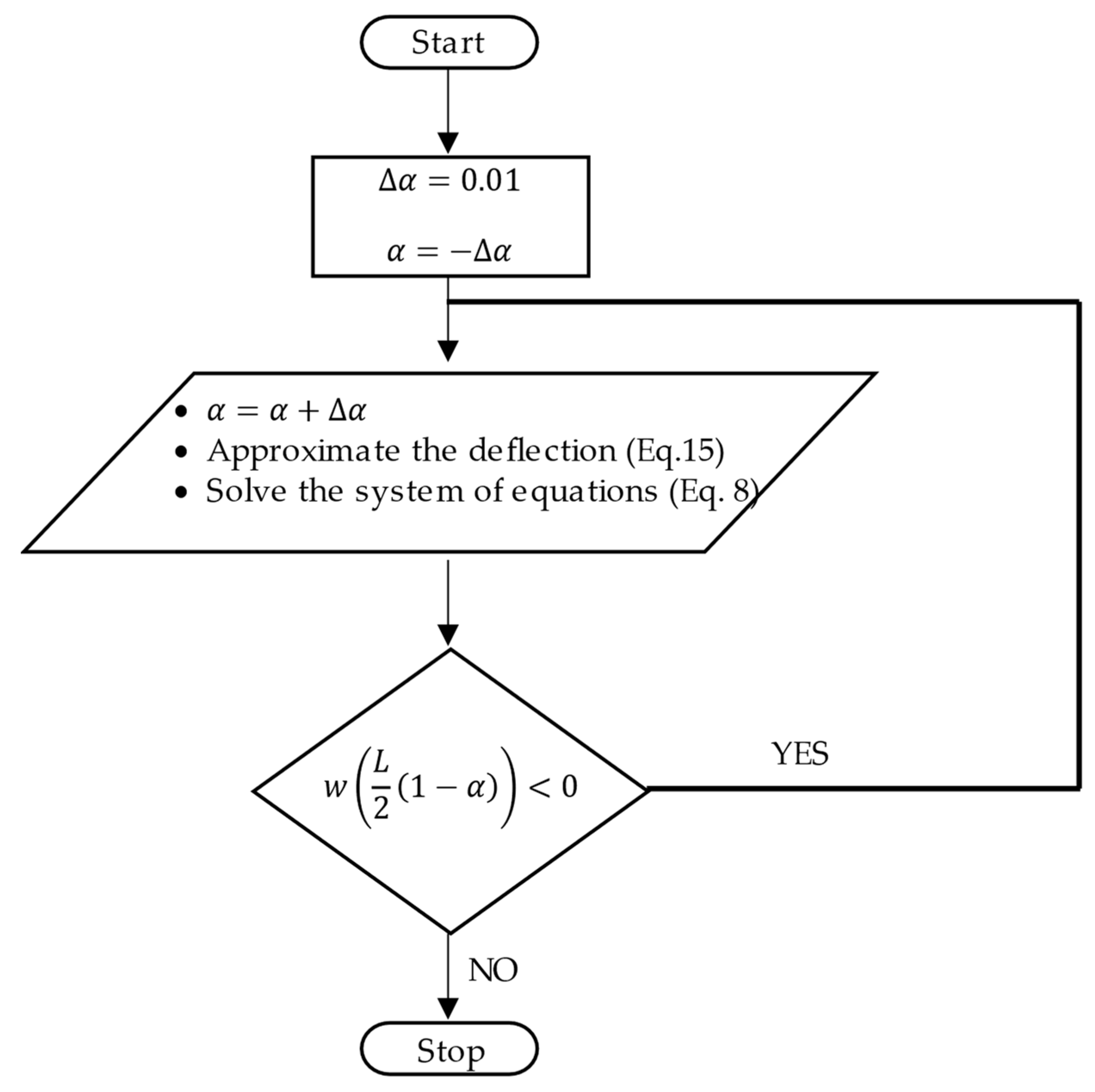
The system of equations (Equation (8)) has been demonstrated taking and (or in the case of a symmetric problem) as given variables. However, these variables are actually unknown and it is proposed herein to be obtained iteratively. Initially, the solution starts by assuming both , then it is increased by an amount which is a small value (say 0.01). The deflection at the lift-off points (/2 and /2) can then be evaluated and if it is found to be positive (downward), the solution stops otherwise it will continue to more iterations. For more explanation, the flow chart shown in Figure 4 is prepared. If the problem is symmetric, however, the flow chart can be reduced to the one shown in Figure 5.
3. Numerical Example and Discussion
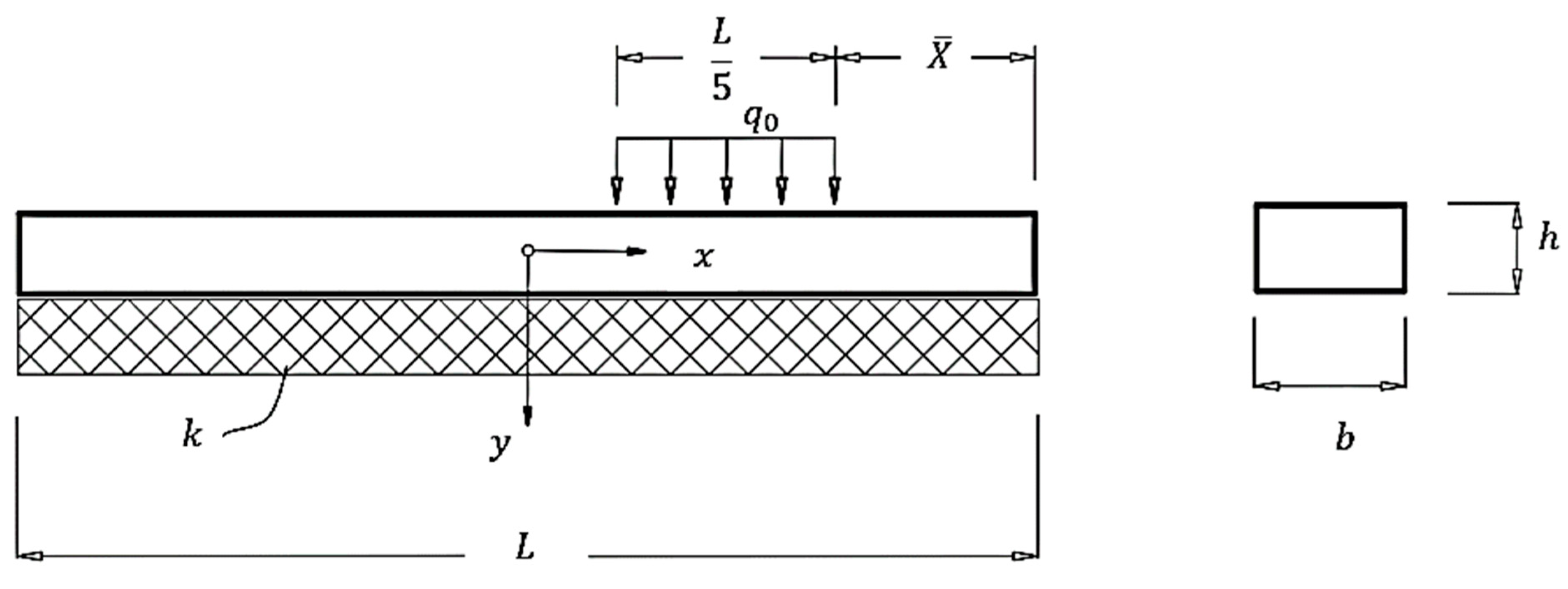
Consider a free–free beam resting on an elastic foundation and loaded with a patched load distributed on one fifth of the beam length as shown in Figure 6. To test the proposed method for symmetrical and asymmetrical problems, two values of the distance are considered (= for a symmetric problem and = for an asymmetric one). The numerical data for all the relevant variables is listed in Table 1.
For the symmetric case (= , the patched load can be expressed mathematically by the following discontinuous function
while, for the asymmetric case, ( = ) can be represented by
where the is a discontinuous function defined by
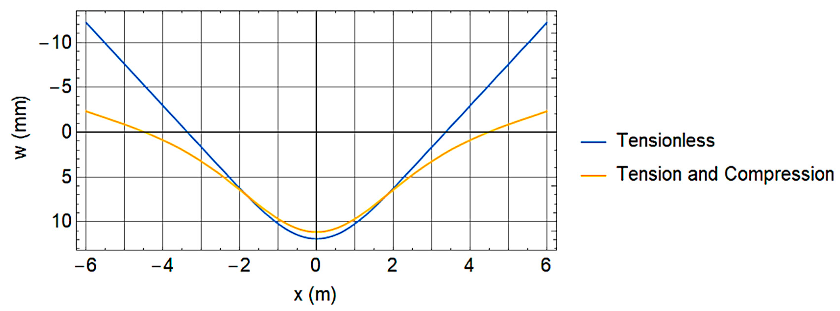
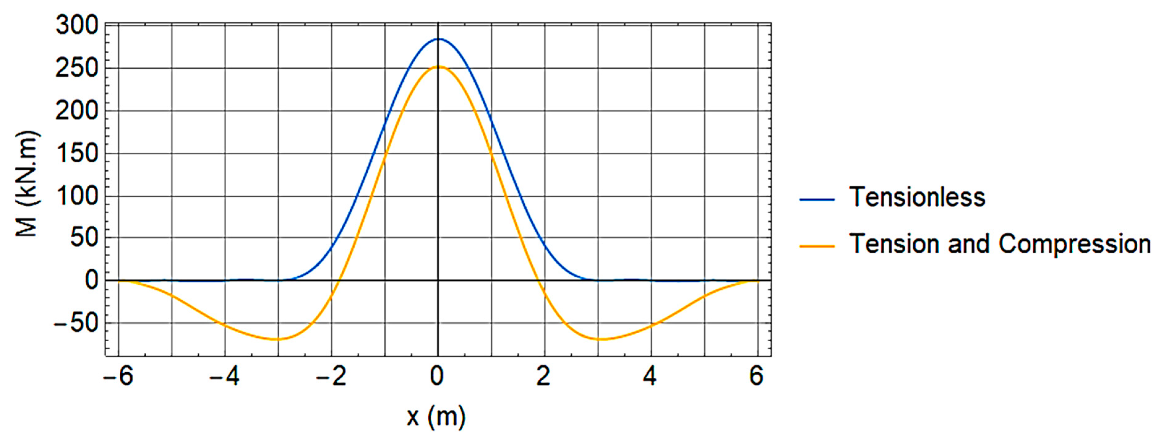
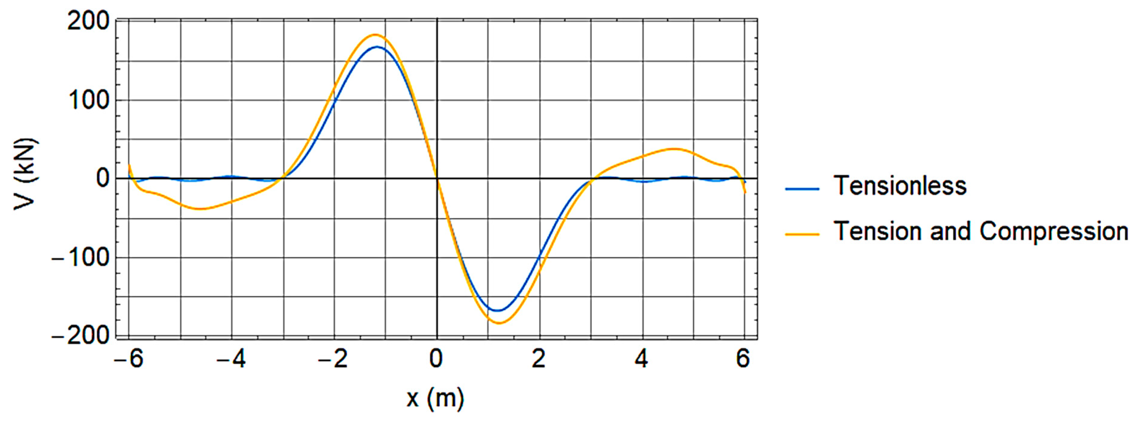
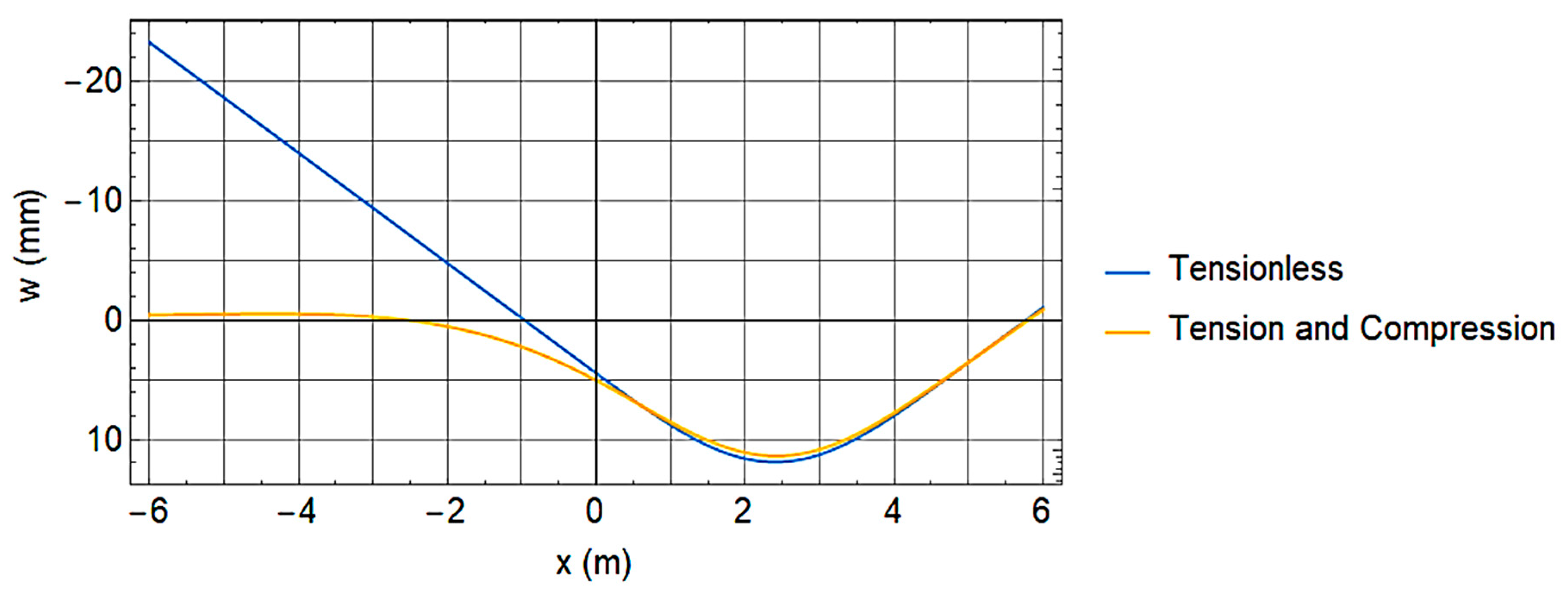
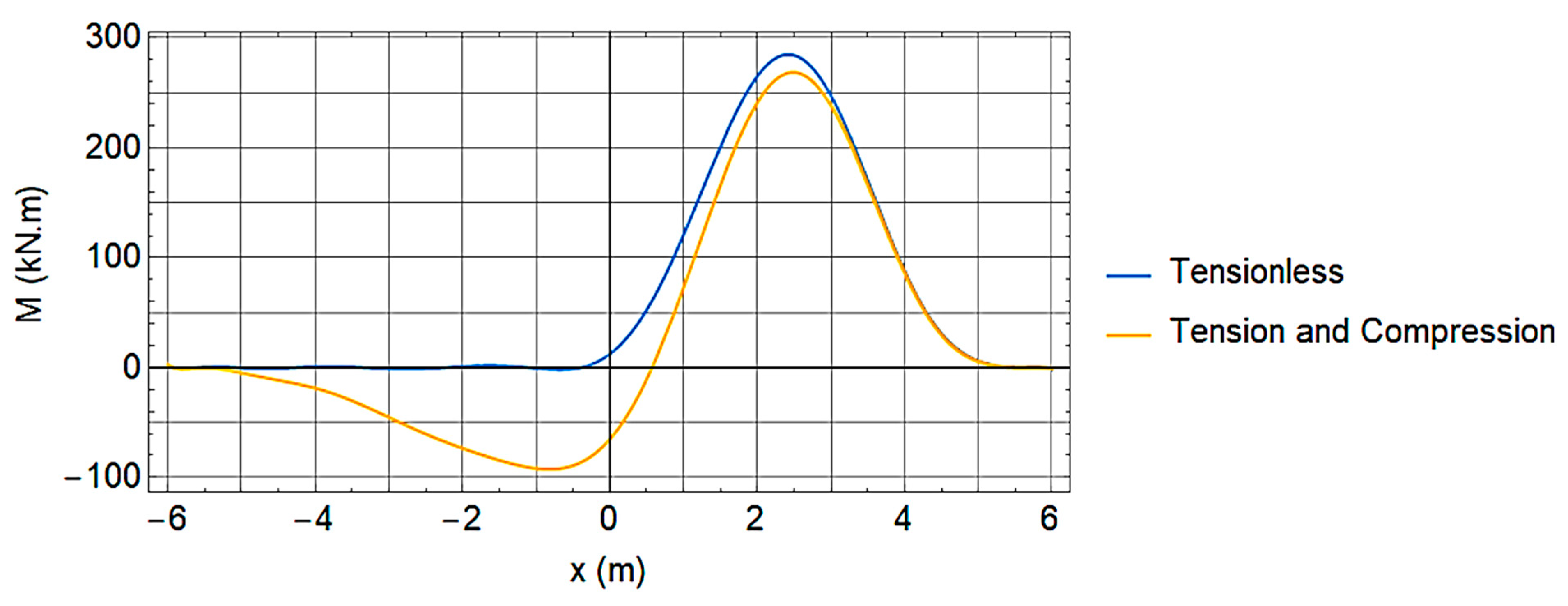
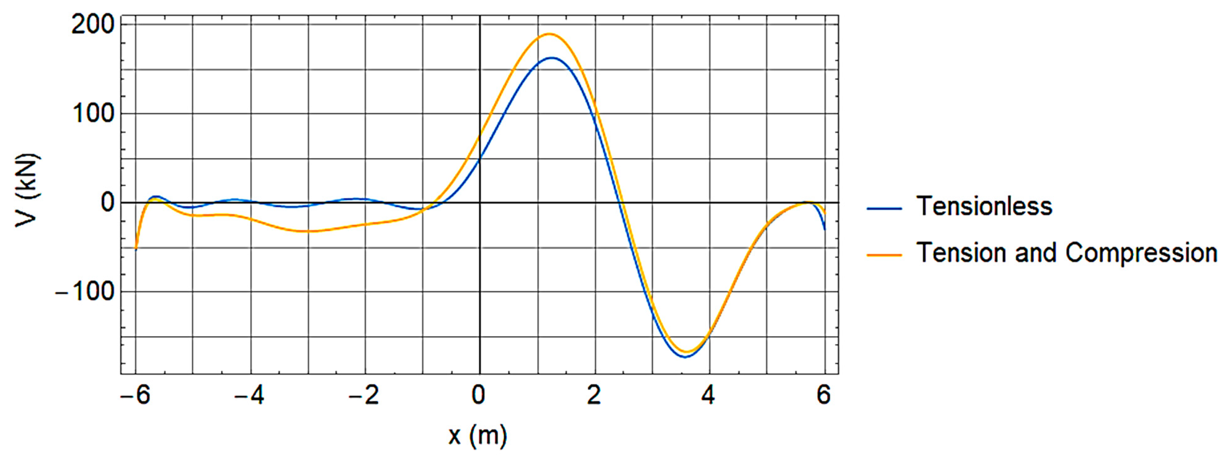
Following the procedure discussed in the flow charts (Figure 4 and Figure 5), the results of the beam deflection, bending moment and shear force are shown in Figure 7, Figure 8, Figure 9, Figure 10, Figure 11 and Figure 12 for symmetric and asymmetric cases, respectively. It can be noted from these figures that consideration of the tensionless foundation considerably affects the results. The high negative deflection noted in cases of tensionless foundation can physically appear as a separation between the beam and the supporting foundation. For clarification, let us denote the zone of negative deflection by the lifted zone and the point that separates between the positive and negative deflection by the lift-off point. It can be clearly seen that the deflection is linearly varied within the lifted zone, which is an indication of zero moment and shear (Figure 8, Figure 9, Figure 11 and Figure 12), since they are of higher derivatives of the deflection (Equations (12) and (13)), and therefore zero stresses. This also proved the capabilities of the adopted Ritz method for satisfying the force boundary conditions of a free–free beam, i.e., .
As a comparison between the tensionless foundation and the Winkler model (Tension and Compression), the noted differences in the results have a major impact not just on the values of the concerned variables but also on the behavior of the structural member. For instance, if the considered beam problem is a model for a reinforced concrete strip foundation, then the design bending moment obtained using the Winkler model (Tension and Compression) will lead to underestimating the positive bending moment and the unnecessary negative bending moment. Using a tensionless model, however, there is only positive bending moment. This is, therefore, the accurate model to use due to the absence of the tension resistance of the soil and, thus, only the bottom of the strip foundation needs to be reinforced. The same can be noticed for the case of deflection, where the deflection using tensionless models is larger and thus requires the designer to exercise an extra degree of caution while evaluating the serviceability requirements such as crack width and allowable deflection.
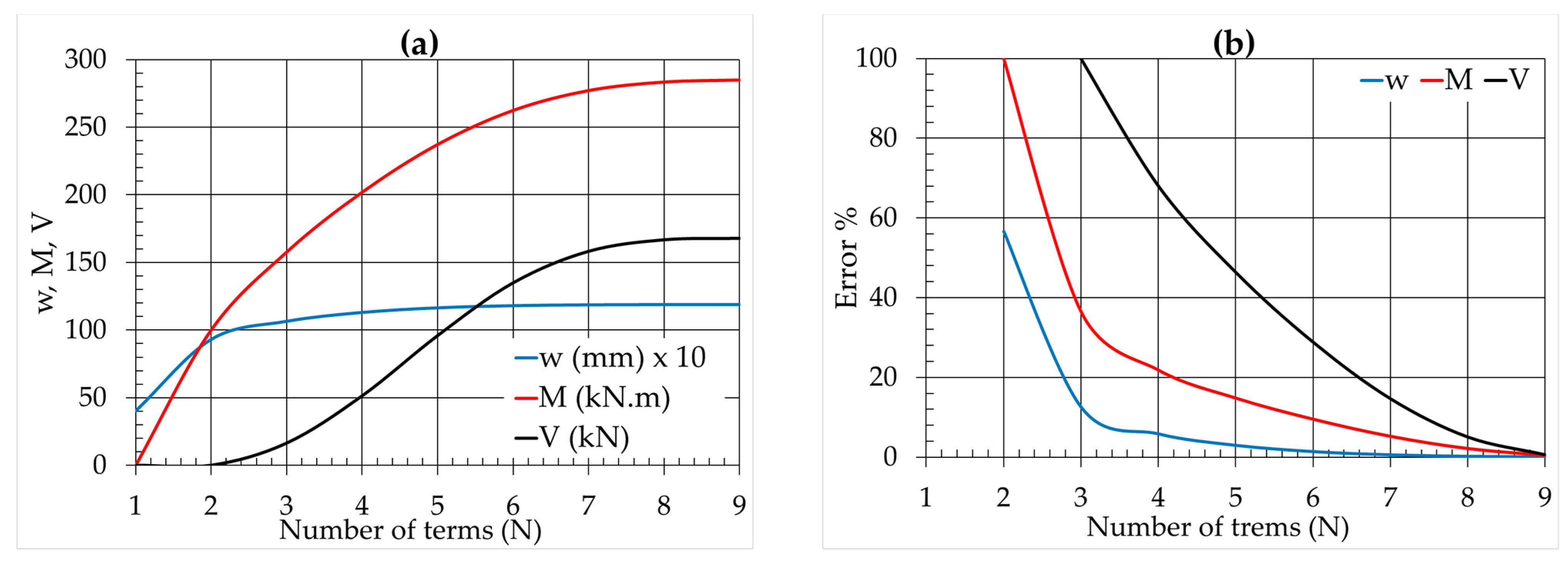
As it has been noted earlier, the number of polynomial terms (N) need to be determined based on the convergence of the problem; as such, Figure 13 was prepared to show the convergence of the deflection, bending moment and shear force for the symmetric case. To properly show the variations in the maximum value of each of these three outputs, the variation of the maximum value with the number of polynomial terms (N) is shown in Figure 13a. It can be noticed from this figure that N of 4 onwards is sufficient to truncate the summation if only accurate deflection is the concern, while more terms (N = 9) are needed if the shear force and bending moments are of interest. The reason for the late convergence of the shear and bending moments is that they involve higher derivatives of the deflection (Equations (12) and (13)), and more polynomial terms are therefore needed. The approximate errors for each of the two subsequent iterations were also evaluated and shown in Figure 13b, which shows that the errors move close to zero with the increase in the polynomial terms until they eventually converge at .
4. Parametric Study
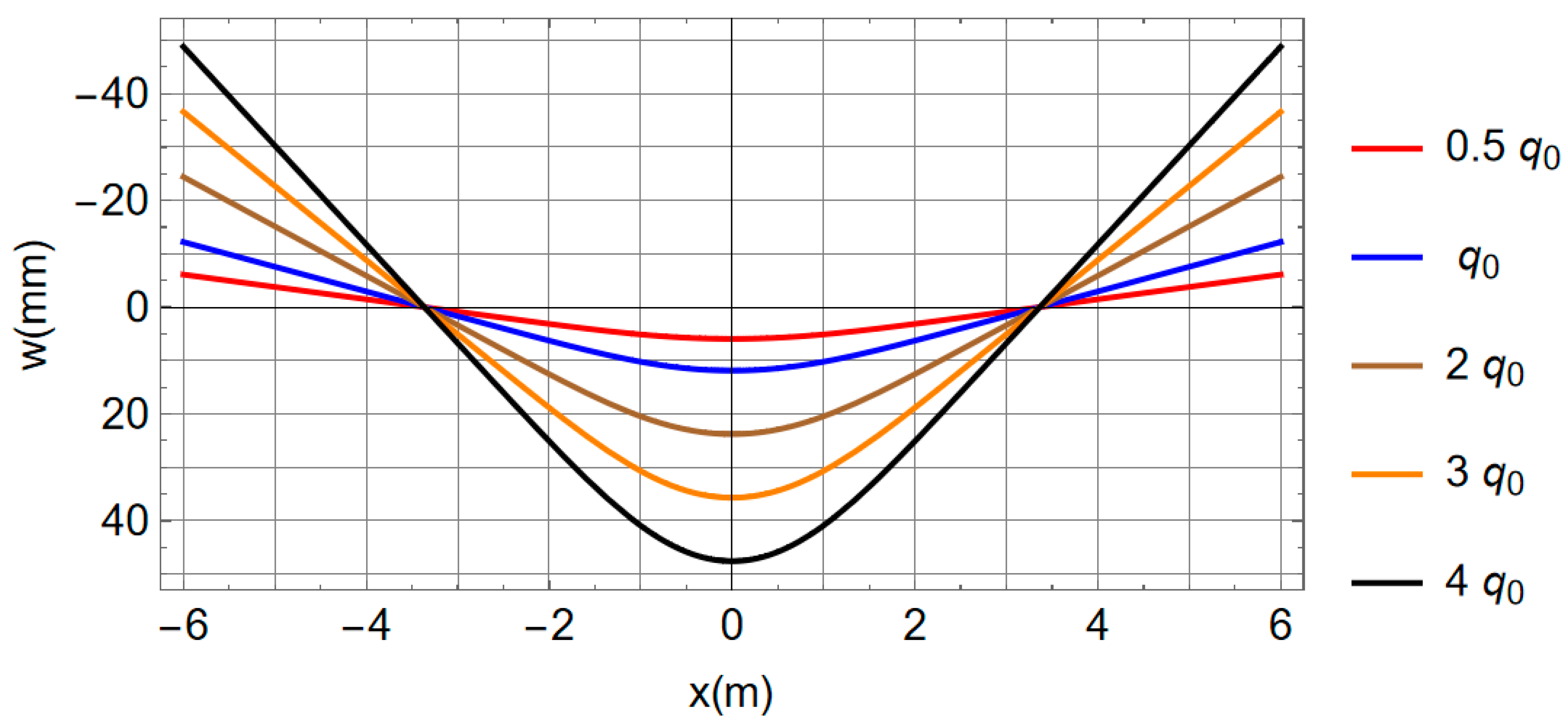
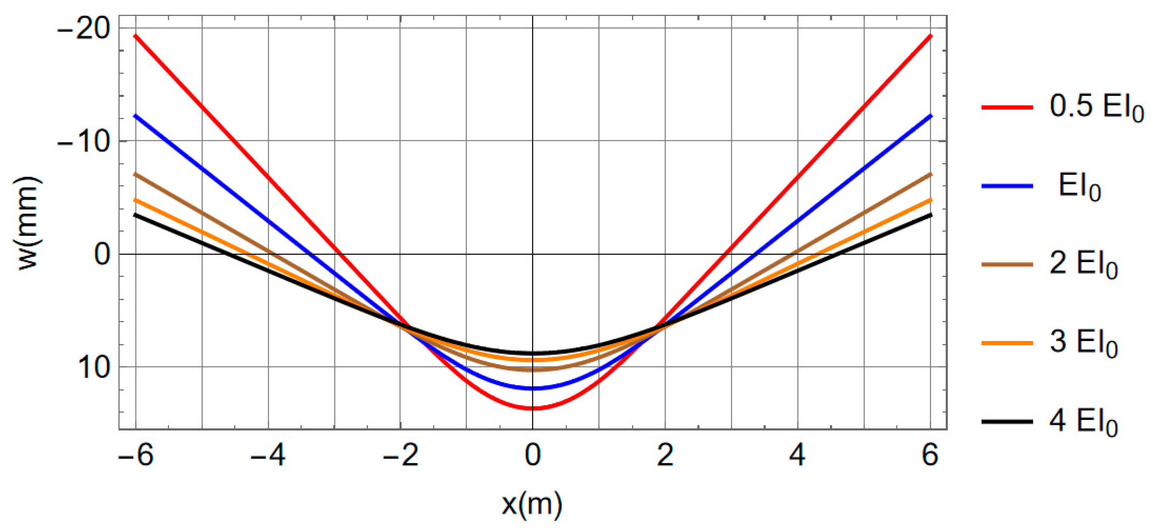
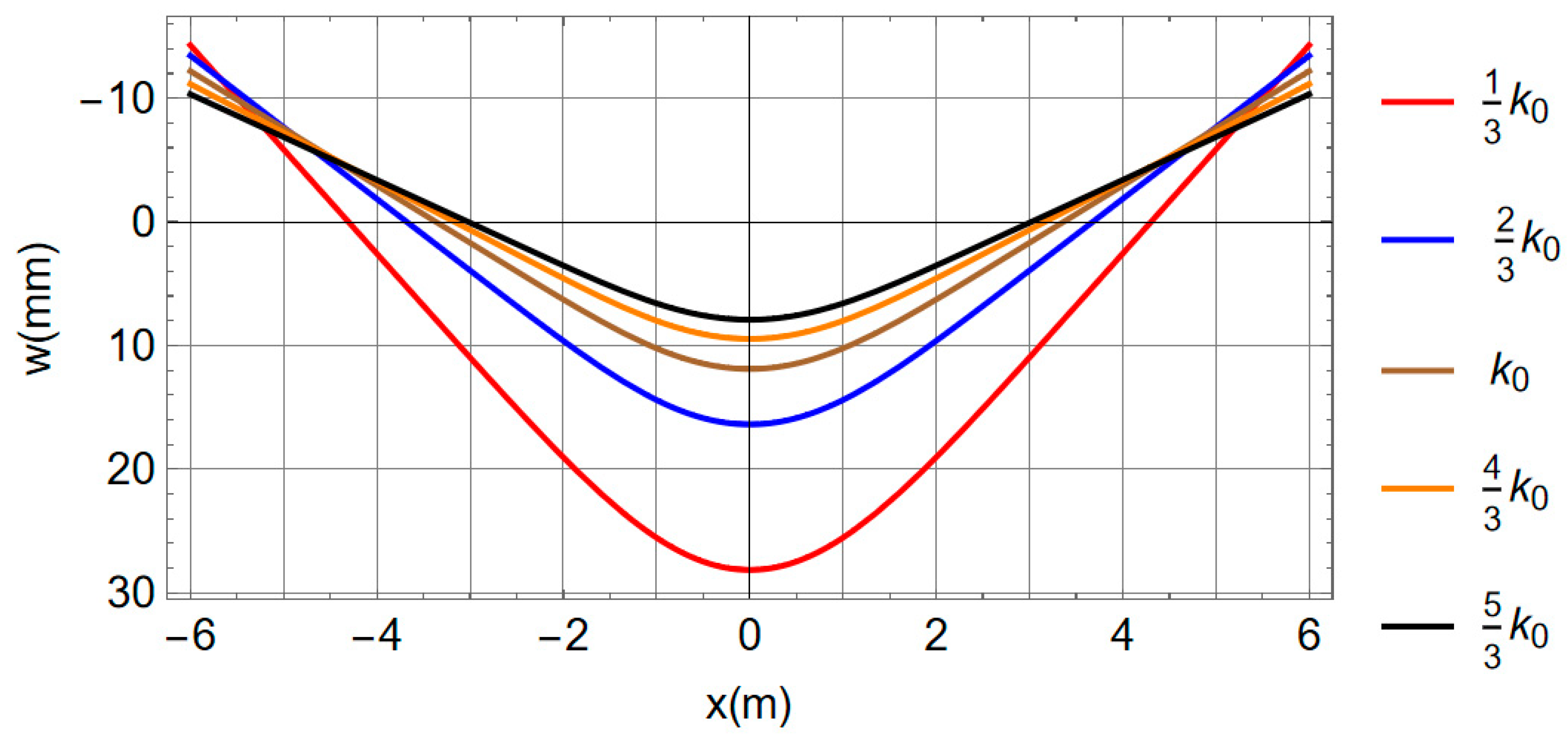
The amount of patched load , the subgrade reaction modulus k, and the beam stiffness EI are the main parameters controlling the behavior of a beam resting on a tensionless foundation. To investigate their impact, a parametric study for the symmetrical case of the previous example, with the parameters shown in Table 2, was conducted. The values of , , and are taken to be , , and 20,000 kN/m2, respectively.
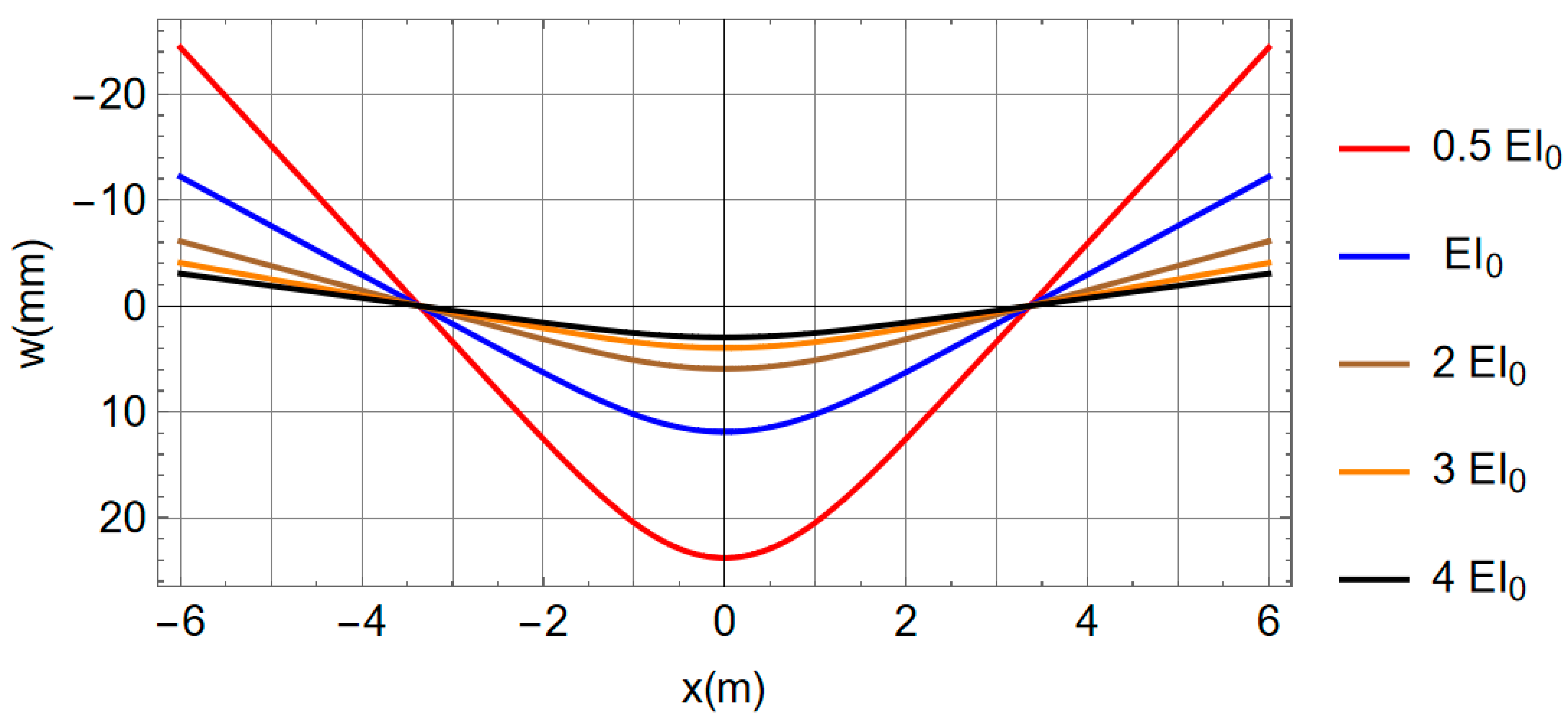
The results of the four cases are shown in Figure 14, Figure 15, Figure 16 and Figure 17. It can be noticed from Figure 14 that the increase in the patched load results in an increase in the deflection, but the non-zero subgrade reaction zone is similar for all load levels. Thus, the lift-off point is independent of the amount of the applied patched load. The lifted zone decreases with the increase in the beam stiffness as in Figure 15 which, in other words, means that greater proportion of the beam length remains in contact with the soil as the beam stiffness increases. From Figure 16, it can be concluded that for soft soil (with low values), the beam tends to have more deflection and less of a lifted zone or more of a non-zero subgrade reaction zone. In both cases of varied stiffness and varied subgrade reaction modulus (Figure 15 and Figure 16), the lift-off point is varied. However, it remains the same while maintaining similar beam stiffness to the subgrade reaction modulus () ratio as in Figure 17.
5. Conclusions
Bending analysis of a completely free beam resting on a tensionless elastic foundation subjected to patched load is presented in this study. The solution is obtained using the Ritz method and an iterative procedure is adopted to converge at the non-zero subgrade reaction zone. A sum of simple polynomials is also adopted to approximate the deflection with unknown constants that are determined through the minimization of the potential energy. The applicability of the proposed iterative procedure is explained though a numerical example that covers both symmetrical and asymmetrical patched load applications. The results of the numerical examples showed a considerable negative deflection which proved the occurrence of a gap between the beam and the supporting soil. They also proved the importance of adopting a tensionless foundation to satisfy the design requirements as compared to the Winkler model which has unrealistic tension capacity of the supporting soil that results in relatively different behavior near the ends of a free–free beam subjected to patched load.
The impact of the main influencing parameters (the amount of load, beam stiffness, and subgrade reaction modulus) is investigated through a parametric study. It is concluded that if the beam stiffness to subgrade reaction modulus (EI/k) ratio is kept constant, the lift-off point will remain similar regardless of which beam is deflecting more. With this same lift-off point, a beam with lower stiffness or higher loads deflects more.
This type of free–free beam has boundary conditions in the form of second and third derivatives of the deflection. These conditions are not required to be satisfied while selecting the approximating functions that describe the deflected shape. As verification, the user of this method should, therefore, ensure that in addition to convergence of the results, the selected number of polynomial terms (N) leads to satisfaction of the bending moment and shear force boundary conditions.
Author Contributions
Conceptualization, A.E.S.M. and M.A.A.-S.; methodology, A.E.S.M.; software, A.E.S.M. and M.A.A.-S.; validation, A.E.S.M. and M.A.A.-S.; investigation, A.E.S.M. and M.A.A.-S.; writing—original draft preparation, A.E.S.M., M.A.A.-S. and A.A.-F.; writing—review and editing, A.E.S.M., M.A.A.-S. and A.A.-F.; visualization, A.E.S.M., M.A.A.-S. and A.A.-F.; supervision, A.E.S.M.; project administration, A.E.S.M. All authors have read and agreed to the published version of the manuscript.
Funding
This research was funded by the Interdisciplinary Research Center for Construction and Building Materials (IRC-CBM) at King Fahd University of Petroleum and Minerals, Project # INCB2213.
Data Availability Statement
A Mathematica code will be provided upon request from the corresponding author.
Acknowledgments
The authors greatly acknowledge the Interdisciplinary Research Center for Construction and Building Materials (IRC-CBM) at King Fahd University of Petroleum and Minerals (KFUPM) for the support provided to complete this study under Project # INCB2213.
Conflicts of Interest
The authors declare no conflict of interest.
References
- Das, B.M.; Sivakugan, N. Principles of Foundation Engineering; Cengage Learning: Boston, MA, USA, 2018. [Google Scholar]
- Bowles, J.E. Foundation Analysis and Design; McGraw Hill: New York, NY, USA, 1988. [Google Scholar]
- McKenzie, W. Design of Structural Elements; Bloomsbury Publishing: London, UK, 2013. [Google Scholar]
- McKenzie, W.M. Design of Structural Masonry; Palgrave New York: New York, NY, USA, 2001. [Google Scholar]
- Weitsman, Y. A tensionless contact between a beam and an elastic half-space. Int. J. Eng. Sci. 1972, 10, 73–81. [Google Scholar] [CrossRef]
- Zhang, Y.; Murphy, K.D. Response of a finite beam in contact with a tensionless foundation under symmetric and asymmetric loading. Int. J. Solids Struct. 2004, 41, 6745–6758. [Google Scholar] [CrossRef]
- Zhang, Y.; Murphy, K.D. Tensionless contact of a finite beam: Concentrated load inside and outside the contact zone. Acta Mech. Sin. 2013, 29, 836–839. [Google Scholar] [CrossRef]
- Zhang, Y.; Liu, X.; Wei, Y. Response of an infinite beam on a bilinear elastic foundation: Bridging the gap between the Winkler and tensionless foundation models. Eur. J. Mech.-A/Solids 2018, 71, 394–403. [Google Scholar] [CrossRef]
- Stephen, N.; Ch’ng, S. The Euler–Bernoulli beam on a tensionless Winkler foundation: A simple problem of receding contact. Int. J. Mech. Eng. Educ. 2018, 46, 375–383. [Google Scholar] [CrossRef]
- Zhang, Y.; Liu, X. Response of an infinite beam resting on the tensionless Winkler foundation subjected to an axial and a transverse concentrated loads. Eur. J. Mech.-A/Solids 2019, 77, 103819. [Google Scholar] [CrossRef]
- Choros, J.; Adams, G. A steadily moving load on an elastic beam resting on a tensionless Winkler foundation. J. Appl. Mech. 1979, 46, 175–180. [Google Scholar] [CrossRef]
- Bhatra, S.; Maheshwari, P. Effect of Adjacent Axle Loads on Uplift of Rails on Geocell-Stone Column Improved Tensionless Foundation. Geotech. Geol. Eng. 2021, 39, 1059–1078. [Google Scholar] [CrossRef]
- Feng, Z. Finite Element Analysis of Beams on Two-Parameter Tensionless Foundations. In Proceedings of the Computational Mechanics’86, Tokyo, Japan, 25–29 May 1986; pp. 443–448. [Google Scholar]
- Celep, Z.; Güler, K.; Demir, F. Response of a completely free beam on a tensionless Pasternak foundation subjected to dynamic load. Struct. Eng. Mech. 2011, 37, 61–77. [Google Scholar] [CrossRef]
- Celep, Z.; Demir, F. Symmetrically loaded beam on a two-parameter tensionless foundation. Struct. Eng. Mech. 2007, 27, 555–574. [Google Scholar] [CrossRef] [Green Version]
- Özmutlu, A. Response of a finite beam on a tensionless Pasternak foundation under symmetric and asymmetric loading. Struct. Eng. Mech. 2008, 30, 21–36. [Google Scholar] [CrossRef]
- Ma, X.; Butterworth, J.W.; Clifton, G.C. Static analysis of an infinite beam resting on a tensionless Pasternak foundation. Eur. J. Mech.-A/Solids 2009, 28, 697–703. [Google Scholar] [CrossRef]
- Nobili, A.; Lanzoni, L. On the stability loss for an Euler beam resting on a tensionless Pasternak foundation. Z. Angew. Math. Phys. 2014, 65, 797–808. [Google Scholar] [CrossRef]
- Zhang, Y. Tensionless contact of a finite beam resting on Reissner foundation. Int. J. Mech. Sci. 2008, 50, 1035–1041. [Google Scholar] [CrossRef]
- Zhang, L.; Zhao, M. New method for a beam resting on a tensionless and elastic-plastic foundation subjected to arbitrarily complex loads. Int. J. Geomech. 2016, 16, 04015093. [Google Scholar] [CrossRef]
- Maheshwari, P. Analysis of beams on tensionless reinforced granular fill-soil system. Int. J. Numer. Anal. Methods Geomech. 2008, 32, 1479–1494. [Google Scholar] [CrossRef]
- Sapountzakis, E.J.; Kampitsis, A.E. Nonlinear analysis of shear deformable beam-columns partially supported on tensionless three-parameter foundation. Arch. Appl. Mech. 2011, 81, 1833–1851. [Google Scholar] [CrossRef]
- Nobili, A. Variational approach to beams resting on two-parameter tensionless elastic foundations. J. Appl. Mech. 2012, 79, 021010. [Google Scholar] [CrossRef]
- Heshmat, T.; Elshabrawy, M. Analytical solution for nonlinear interaction of euler beam resting on a tensionless soil. Proc. Int. Struct. Eng. Constr. 2021, 8, GFE-02–GFE-06. [Google Scholar] [CrossRef]
- Ioakimidis, N.I. Inequality constraints in one-dimensional finite elements for an elastic beam on a tensionless Winkler foundation. Finite Elem. Anal. Des. 1996, 24, 67–75. [Google Scholar] [CrossRef]
- He, G.; Li, X.; Lou, R. Nonlinear FEA of higher order beam resting on a tensionless foundation with friction. Geomech. Eng. 2016, 11, 95–116. [Google Scholar] [CrossRef]
- Ma, X.; Butterworth, J.W.; Clifton, G.C. Response of an infinite beam resting on a tensionless elastic foundation subjected to arbitrarily complex transverse loads. Mech. Res. Commun. 2009, 36, 818–825. [Google Scholar] [CrossRef]
- Nobili, A. Superposition principle for the tensionless contact of a beam resting on a Winkler or a Pasternak foundation. J. Eng. Mech. 2013, 139, 1470. [Google Scholar] [CrossRef]
- Celep, Z.; Güler, K. Axisymmetric forced vibrations of an elastic free circular plate on a tensionless two parameter foundation. J. Sound Vib. 2007, 301, 495–509. [Google Scholar] [CrossRef]
- Chróścielewski, J.; Szymczak, C.K. Optimal Design of Plates Resting on Tensionless Foundation. Model. Sinulation Control B 1997, 11, 29–37. [Google Scholar]
- Lezgy-Nazargah, M.; Mamazizi, A.; Khosravi, H. Analysis of shallow footings rested on tensionless foundations using a mixed finite element model. Struct. Eng. Mech. 2022, 81, 379–394. [Google Scholar] [CrossRef]
- Zhang, B.-Q.; Chen, F.-Q.; Wang, Q.-Y.; Lin, L.-B. Analytical model of buried beams on a tensionless foundation subjected to differential settlement. Appl. Math. Model. 2020, 87, 269–286. [Google Scholar] [CrossRef]
- Hsu, Y.S. Finite element approach of the buried pipeline on tensionless foundation under random ground excitation. Math. Comput. Simul. 2020, 169, 149–165. [Google Scholar] [CrossRef]
- Ugural, A.C. Stresses in Beams, Plates, and Shells; CRC Press: Boca Raton, FL, USA, 2009. [Google Scholar]
- Ugural, A.C.; Fenster, S.K. Advanced Mechanics of Materials and Applied Elasticity; Pearson Education: London, UK, 2011. [Google Scholar]
Figure 1.
A free–free beam resting on Winkler foundation.

Figure 2.
A free–free beam resting on tensionless foundation.

Figure 3.
A simplified diagram of a free–free beam resting on tensionless foundation.

Figure 4.
Flow chart on solving an asymmetric free–free beam on tensionless foundation.

Figure 5.
Flow chart on solving a symmetric free–free beam on tensionless foundation.

Figure 6.
Free–free beam on tensionless foundation subjected to patched load.

Figure 7.
The deflection results for the symmetric case (= .

Figure 8.
The bending moment diagram for the symmetric case (= .

Figure 9.
The shear force diagram for the symmetric case ( = .

Figure 10.
The deflection results for the asymmetric case (= .

Figure 11.
The bending moment diagram for the asymmetric case (= .

Figure 12.
The shear force diagram for the asymmetric case (= .

Figure 13.
The convergence of the deflection, bending moment, and shear force at middle of the beam (a) values and (b) percentage errors.
Figure 13.
The convergence of the deflection, bending moment, and shear force at middle of the beam (a) values and (b) percentage errors.

Figure 14.
The beam deflection at different load levels (Case 1).

Figure 15.
The beam deflection at different stiffness levels (Case 2).

Figure 16.
The beam deflection at different subgrade reaction levels (Case 3).

Figure 17.
The beam deflection at different stiffness levels and maintaining same ratio (Case 4).


Table 1.
The numerical data for Example 1.
| Item | Value |
|---|---|
| Elastic modulus of the beam material (E) | 25 GPa |
| Subgrade reaction modulus (k) | 20,000 kN/m2 |
| Beam length (L) | 12.0 m |
| Depth of the beam cross-section (h) | 0.40 m |
| Width of the beam cross-section (b) | 0.60 m |
| The patched load q0 | 400 kN/m |
Table 2.
The adopted parameters and their levels.
| Case | Parameter | Levels | Other Beam Variables |
|---|---|---|---|
| Case 1 | |||
| Case 2 | , | ||
| Case 3 | |||
| Case 4 |
* The subgrade reaction is also varied to maintain the ratio of .
Publisher’s Note: MDPI stays neutral with regard to jurisdictional claims in published maps and institutional affiliations. |
© 2022 by the authors. Licensee MDPI, Basel, Switzerland. This article is an open access article distributed under the terms and conditions of the Creative Commons Attribution (CC BY) license (https://creativecommons.org/licenses/by/4.0/).
Share and Cite
MDPI and ACS Style
Musa, A.E.S.; Al-Shugaa, M.A.; Al-Fakih, A. Free–Free Beam Resting on Tensionless Elastic Foundation Subjected to Patch Load. Mathematics 2022, 10, 3271. https://0-doi-org.brum.beds.ac.uk/10.3390/math10183271
AMA Style
Musa AES, Al-Shugaa MA, Al-Fakih A. Free–Free Beam Resting on Tensionless Elastic Foundation Subjected to Patch Load. Mathematics. 2022; 10(18):3271. https://0-doi-org.brum.beds.ac.uk/10.3390/math10183271
Chicago/Turabian StyleMusa, Abubakr E. S., Madyan A. Al-Shugaa, and Amin Al-Fakih. 2022. "Free–Free Beam Resting on Tensionless Elastic Foundation Subjected to Patch Load" Mathematics 10, no. 18: 3271. https://0-doi-org.brum.beds.ac.uk/10.3390/math10183271
Note that from the first issue of 2016, this journal uses article numbers instead of page numbers. See further details here.