RISC Conversions for LNS Arithmetic in Embedded Systems


Institute of Automotive Mechatronics, Faculty of Electrical Engineering and Information Technology, Slovak University of Technology in Bratislava, 812 19 Bratislava, Slovakia
*
Author to whom correspondence should be addressed.
Mathematics 2020, 8(8), 1208; https://0-doi-org.brum.beds.ac.uk/10.3390/math8081208
Submission received: 19 June 2020
/
Revised: 17 July 2020
/
Accepted: 20 July 2020
/
Published: 22 July 2020
(This article belongs to the Special Issue Advances and Novel Approaches in Discrete Optimization)
Abstract
:The paper presents an original methodology for the implementation of the Logarithmic Number System (LNS) arithmetic, which uses Reduced Instruction Set Computing (RISC). The core of the proposed method is a newly developed algorithm for conversion between LNS and the floating point (FLP) representations named “looping in sectors”, which brings about reduced memory consumption without a loss of accuracy. The resulting effective RISC conversions use only elementary computer operations without the need to employ multiplication, division, or other functions. Verification of the new concept and related developed algorithms for conversion between the LNS and the FLP representations was realized on Field Programmable Gate Arrays (FPGA), and the conversion accuracy was evaluated via simulation. Using the proposed method, a maximum relative conversion error of less than ±0.001% was achieved with a 22-ns delay and a total of 50 slices of FPGA consumed including memory cells. Promising applications of the proposed method are in embedded systems that are expanding into increasingly demanding applications, such as camera systems, lidars and 2D/3D image processing, neural networks, car control units, autonomous control systems that require more computing power, etc. In embedded systems for real-time control, the developed conversion algorithm can appear in two forms: as RISC conversions or as a simple RISC-based logarithmic addition.
1. Introduction
The Logarithmic Number System (LNS) provides comparable range and precision as the floating point (FLP) representation, however—for certain applications—it can surpass it in terms of complexity. The range of logarithmic numbers depends on the exponent’s integer part, and the precision is defined by its fraction part [1]. Yet, LNS would outperform FLP only if the logarithmic addition and subtraction can be performed with at least the same speed and accuracy as FLP [2].
The long history of LNS numbers dates back to the 1970′s when the “logarithmic arithmetic” for digital signal processing was introduced [3]. To avoid negative logarithms, a complementary notation for LNS was introduced in [4]. Architecture for the LNS-based processor was proposed in [5]. Implementations of basic arithmetic operations on FPGA [6] using FLP and LNS have shown that the multiplication and division operations are more effective if using LNS, as they require fewer area resources and have a significantly lower time latency. Otherwise, addition and subtraction are more suitable using FLP representation. A higher efficiency of some LNS operations was a motivation for using the LNS format for the realization of control algorithms for the autonomous electric vehicle developed within a running research project.
Nowadays, LNS representation is implemented in various applications, such as deep-learning networks [7], Cartesian to polar coordinates converters [8], or embedded model predictive control [9].
In a very interesting paper [10], it is proposed how numbers close to zero can be represented in the denormal LNS method (DLNS) using either fixed-point or LNS representations, guaranteeing constant absolute or constant relative precisions, respectively. Up to now, LNS have not been standardized.
Various methods have been developed to decrease the costs and complexity of LNS implementation, e.g., interpolation, co-transformation, multipartite tables, etc. [11,12,13]. Typically, there are three main categories of LNS arithmetic techniques: lookup tables, piecewise polynomial approximation, and digit–serial methods [14].
Generally, LNS addition and subtraction are carried out based on the evaluation of the transcendental functions as follows:
where a, b are logarithmic numbers.
Signal processing in embedded systems based on LNS has three stages: logarithmic conversions, simple operations, and antilogarithmic conversions. In the first processing stage, logarithmic conversions are applied to convert binary numbers into logarithmic ones. In the second stage, simple operations are used to perform corresponding calculations, such as addition and subtraction. In the last stage, logarithmic numbers are converted back to binary ones. There are many approaches to solving logarithmic conversion that can be classified into three categories: memory-based methods [15,16], mathematical approximations [6], and shift-and-add-based methods [11,13,17,18,19,20]. Very fast conversions (e.g., shift-and-add) allow us to combine calculations in LNS and FLP systems and design hybrid LNS/FLP processors [13,21,22]. In hybrid systems, the conversions are carried out several times during the calculation, not only the first and last phases.
Using memory-based methods, fast and more accurate conversions are achieved; however, memory size costs may increase significantly while the bit-width of the inputs increases. On the other hand, using polynomial approximations will reduce the area costs, while sacrificing the accuracy and speed. Approximation-based methods almost always use a multiplication operation, for example, an antilogarithmic converter [6] uses 20 multipliers and achieves a latency of more than 70 ns. Compared with these two kinds of implementation, shift-and-add methods can be used to achieve better design tradeoffs between accuracy, memory costs, and speed. All the above-mentioned “shift-and-add” methods achieve a latency of less than 1 ns at the cost of a low accuracy (above 1% relative error [20]) except for [23], where the attained accuracy of the LNS/FLP conversions is 0.138%. Using the proposed looping-in-sectors method in combination with a very simple approximation based on bit manipulations, a radical increase in accuracy and an acceptably low latency can be achieved.
The logarithmic and antilogarithmic conversions are a gateway to LNS algorithms. Yet, the conversions are not freely available from FPGA producers [24] and, thus, must be implemented by our own means. Furthermore, the above methods available in the literature do not meet our requirements in that the accuracy of modern industrial sensors is better than 0.1%, and sampling periods in embedded systems for motion control are less than 1 ms, which places high demands on conversion speed and application calculations. Therefore, our motivation was to develop a simple and efficient FLP/LNS conversion guaranteeing sufficient accuracy and speed, which will be a “golden mean” between the accurate but complex approximation methods and the very efficient and fast (up to 1ns) but inaccurate (relative error higher than 1%) shift-and-add methods.
Embedded systems are expanding into increasingly demanding applications, such as camera systems, lidars and 2D/3D image processing, neural networks, car control units, autonomous control systems that require more computing power, etc. A necessary reliability and functional safety are often based on redundancy of two/three channel technologies. Therefore, alternative calculations (one option is LNS) on independent HW and SW (hardware and software) solutions are needed; outputs of the independent channels are then compared according to the principles of fault tolerant systems (e.g., two out of three).
However, embedded control systems based on LNS arithmetic that operate in real-time necessitate an efficient conversion in every sampling period. Input data from sensors, counters, A/D converters, etc., are typically fixed-point (FXP) numbers, thus they have to be converted to LNS, and, the other way round, the LNS arithmetic results are to be converted back to the FXP format conventionally required by typical output devices (actuators). In this paper, the focus is on conversions between LNS and FLP, conversions from FXP to FLP and back are supposed to be resolved.
The Xilinx’s industry-leading tool suite natively supports different FLP precisions including half (FLP16), single (FLP32), and double (FLP64) precisions, as well as fixed-point data types. The added flexibility of custom precision is also available in MATLAB System Generator for DSP toolbox. The FLP to FXP conversion is dealt with in [24], however the LNS data type is not yet officially supported and conversions from LNS to FLP and back are not available in FPGA libraries.
This paper presents an application of the proposed RISC conversions for logarithmic addition using the Reduced Instruction Set Computing (RISC) realizable just by means of simple operations without using multiplication, etc. Herein, RISC indicates a set of simple computer operations (add, minus, shift by 2, i.e., multiplication/division, logical operations, and bit manipulations). The proposed approach has the ambition to apply just the above-mentioned RISC operations fully excluding multiplication, division, and all other functions (log, square, …). Using the unified format of LNS and FLP, conversion between them can be realized only by dealing with the mantissa and the fraction. To reduce memory requirements for conversions, a novel method called “looping in sectors” was developed.
The paper presents a novel effective RISC-based method, which uses the so-called “looping-in-sectors” procedure and a simple interpolation in the conversion between FLP and LNS number representations. The novel algorithm of logarithmic addition based on the developed conversions performs differently from previously known approaches. The partial results on the development of RISC conversions and algorithms for LNS [25] are completed by the conversion algorithm from LNS to FLP and its realization on FPGA.
The paper is organized as follows. In Section 2, an overview of FLP and LNS number representations is provided. Section 3 presents two developed algorithms of the RISC conversion between both systems. A simple interpolation method along with accuracy analysis are dealt with in Section 4. Principle of the RISC-based LNS addition is explained in Section 5. FPGA realization of the RISC conversion is demonstrated on a simple example in Section 6. Discussion on obtained results, their potential, and future research concludes the paper.
2. Number Systems
Let us briefly revisit the FLP and LNS number representations. According to Table 1, a floating point (FLP) number is expressed as follows:
where m is a mantissa, and N is an integer or a real number from the intervals 〈0, M − 1〉 or ⟨0, M〉, respectively. M is the maximum of the mantissa (fractional part) with t bits.
Table 2 shows the principle of an LNS number representation; according to it:
The logarithmic fraction f can be expressed as follows:
where F is an integer in the range 〈〉 or a real number in the range .
In terms of individual bits, the whole exponent Ef consists of “integer bits” (ix) and “fractional bits” (fy), placed next to each other. SE denotes the sign of the exponent.
For both numerical systems, the number of bits of the exponent E corresponds to the range of the numbers, and the number of the fractional part bits reflects the accuracy.
2.1. Two Possible Representations of LNS Numbers
The mantissa m is always a positive number (0 ≤ m < 1), but the logarithmic fraction depends on the sign of the exponent SE. Still, there is also another possibility to represent LNS fraction as always positive, similar to mantissas.
Let a number X < 1, E ≤ 0 and a fraction f < 0. FSE and FAP are positive real numbers from 〈0, M〉.
where FAP is a complement of FSE to the range of the fraction M, i.e.,
For numbers X > 1, FAP = FSE and the integer E is unchanged. FAP is an always-positive fraction.
The sign of FSE is the same as the sign SE. For the sake of completeness note that for X = 1 there are two possible ways (i.e., possible codes) to represent zero. In the FSE representation, E= ±0 and the fraction FSE = 0 (the same as for X = −1). In the FAP representation there is no such anomaly; the conversion between FAP and FSE proceeds (7) and (8).
2.2. Equivalence between FLP and LNS
The FLP (2) and LNS (4) representations are equivalent if integer parts of both representations are equal numbers of e-bits, and both the fraction and the mantissa are equal numbers of t-bits. It is also necessary to use an always positive fraction FAP. The sign S and the exponent E are matching:
Let NX denote the mantissa (FLP) and LX = FAP is the always positive fraction (LNS). The subscript “x“ specifies that they represent (code) the equivalent number X in diverse number systems. Using the following conversion between the mantissa and the fraction, equivalence of FLP and LNS can be attained:
where and LZ, NZ are positive integers from the interval 〈〉 or positive real numbers within the interval 〈〉. In the same range, sequences of integers for L and N are geometric and arithmetic, respectively. The integer form of L and N is used to address the look up table (LUT) memory, while their real form is needed to attain a required accuracy. By extending the number of bits of the lower fraction and mantissa to t + r bits, the accuracy can be improved. Using the following corrections, the mutual number conversions over the interval 〈〉 can be defined as follows:
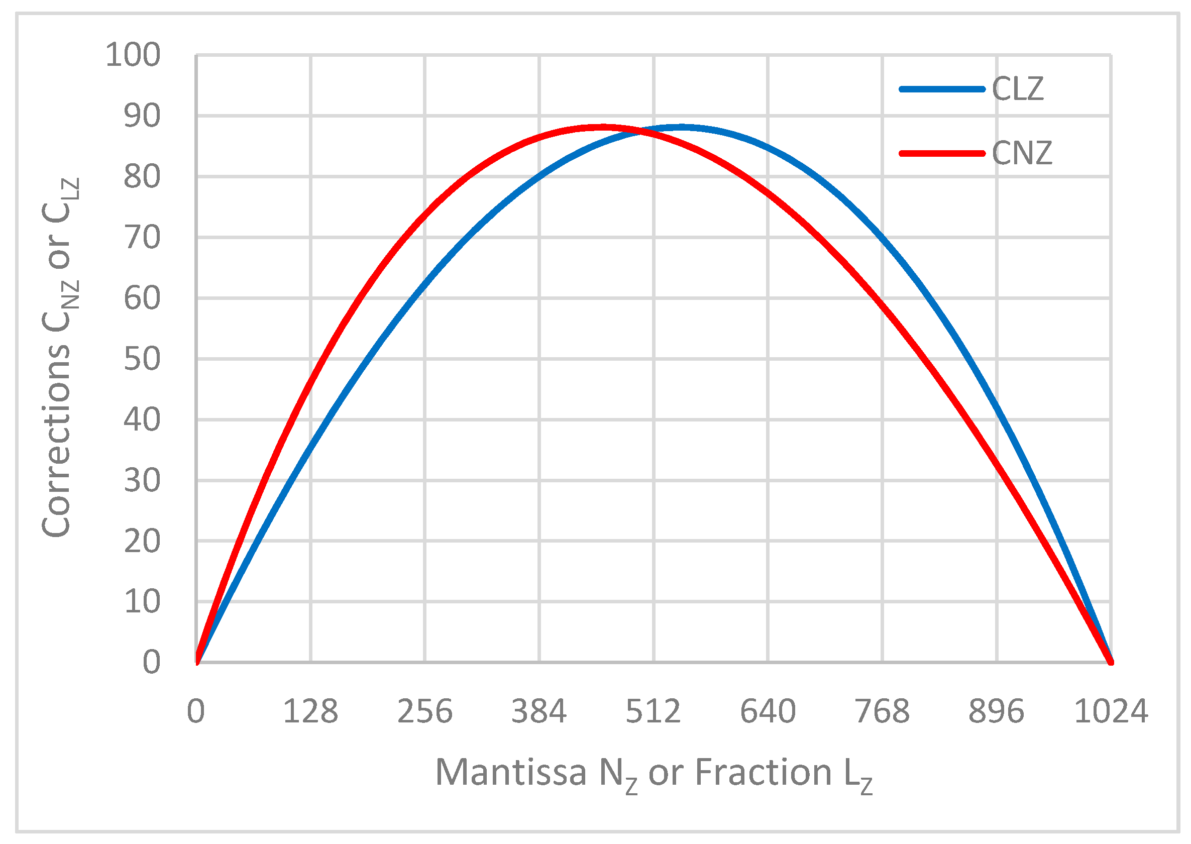
where CNZ and CLZ are correction functions for conversions in both directions:
From the corresponding diagrams in Figure 1 it is evident that both functions have the same maximum, however at various arguments:
3. RISC-Based Conversion between FLP and LNS
If we assume equivalence of the FLP and LNS numbers, the conversion can be completed between the fraction and mantissa. The proposed algorithm aims to use RISC-type computing operations to reduce memory consumption and costs, while achieving as high accuracy as possible. In the Reduced Instruction Set Computing (RISC), operations of multiplication, division, square, square root, logarithm, etc., are not used.
3.1. Conversion from LNS to FLP
The conversion from LNS to FLP is carried out using (12) and (14). When converting LZ it is required to cover the whole range of the fraction, guarantee a sufficient accuracy, and avoid a large memory consumption. According to the proposed approach, LZ is split in two parts:
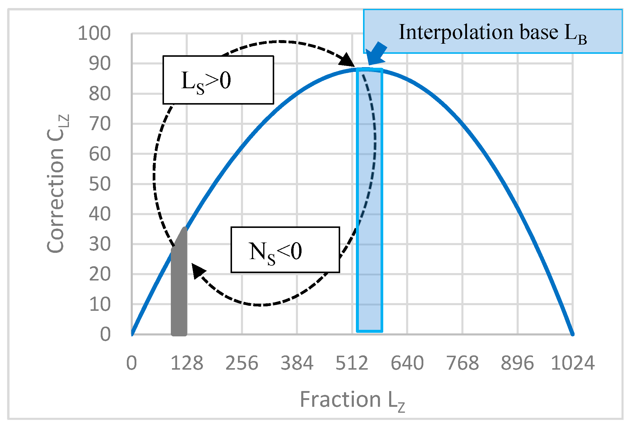
where LS is relevant for each sector and LB for the common base. The fraction is split into sectors (e.g., 32 sectors in our case). In (15), represents a relocation of the converted number to the base —a part of the CLZ function diagram placed in the close vicinity of the extreme (Figure 2).
To obtain NB from LB, a simple interpolation is performed (as described in Section 5). The calculation loop closes by applying Ns in (18). This procedure was named “looping in sectors” (LiS) by the first author. Mathematically, the LiS method is expressed by the Equations (16)–(18):
The equivalent FLP representation in the mantissa form is as follows:
From (17) results:
By appropriately choosing Ns and calculating corresponding Ls according to (11), a conversion look-up table LUT1LS was generated using 10 bits, i.e., M = 1024 (Table 3). For each sector, the numbers Ns and Ls form a pair when using the looping-in-sectors method.
The procedure for selecting the sector number Ns is as follows. Choose the interval for the “interpolation base LB“ in the vicinity of the argument (541.456765) of the extreme of the correction function in Figure 2. In our case, the minimum interval is min LB = 520. Each sector has a minimum, denoted “min Lz” in Table 3. We choose Ns with three active bits (Table 4) under the condition Ls > (520-minLz) where Ls is calculated according to (11) with the required accuracy. The choice of Ns is specific in each sector; as a result the interval for the interpolation base is not 32 but 40 (wider) where
The RISC conversion procedure from L to N is described in the Algorithm 1 (input variable is the fraction LZ; the sign S and the exponent E do not change):
| Algorithm 1 RISC conversion from L to N |
|
is calculated as follows:
where shift1, shift2, shift3 denote shifting bits of NB according to Table 4, which is suitable for FPGA implementation (it substitutes the original product NB * NS/M). In (18), we modified the expression NS/M to 3 “shift operations” according to the weights (w bits) of the 3 active bits (Table 4). M = 210 represents a shift by 10 places to the right.
The variable NS was chosen to include just 3 “active bits”, i.e., bits with nonzero (+1 or −1) values, see Table 4. The algorithm results that the conversion can be performed as RISC, i.e., using just elementary computer operations: addition, subtraction, shifting (multiplication and division by 2), and addressing/reading from the memory.
3.2. Conversion from FLP to LNS
Conversion from FLP to LNS is based on Equations (11) and (13) and modified Equations (16)–(18). Details are described in [25].
The RISC conversion from N to L (input variable is the mantissa NZ; the sign S and the exponent E do not change) is described in Algorithm 2:
| Algorithm 2 RISC conversion from N to L |
|
is calculated as follows:
Note that (20) is a modification of (18). Again, NS has to be chosen to include just 3 “active bits”. It can be concluded that both conversions from FLP to LNS and vice versa can be performed as RISC, using just elementary computer operations.
4. Interpolation and Accuracy
For both FLP and LNS, the accuracy is given by the number of bits of the mantissa and the fraction; it usually decreases due to approximation or interpolation. In the effective RISC conversion design, a simple interpolation is based on bit manipulation. The interpolation is demonstrated on the LNS to FLP conversion. The base generated according to (12) and (14) and the corresponding look-up table LUT2NB were chosen so that the base falls within the plateau in the close vicinity of the CLZ function maximum (Figure 2).
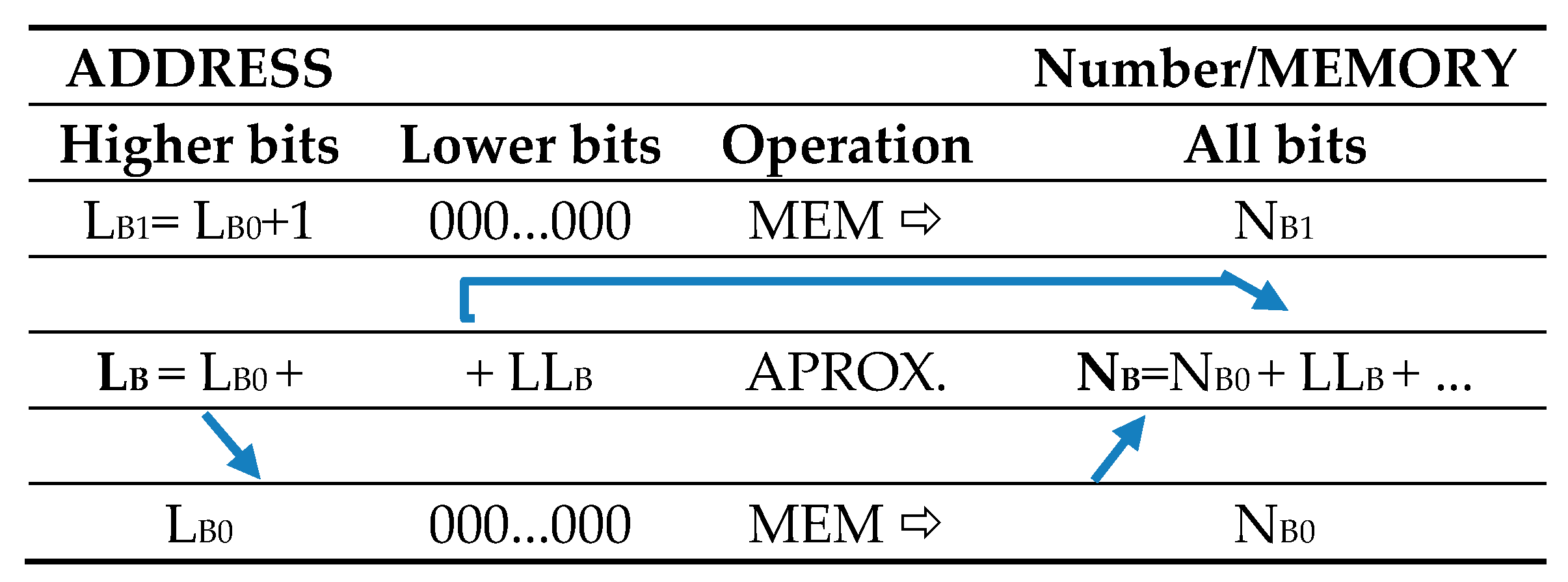
The plateau region was intentionally chosen as the interpolation base because differences between the “adjacent” logarithmic values of LB and the arithmetic sequence values of NB are approximately matching; this allows us to interpolate between two points in the table in a very simple way (Figure 3).
Approximating the mantissa NB (denoted as the interpolation base LB in Figure 2) using the look-up table LUT2NB is demonstrated in Figure 3:
- The fraction LB is rounded to the higher n bits (e.g., n = 10), thus obtaining the address LB0. Then, NB0 is read from the memory.
- Lower bits of LB are denoted as LLB:
- The simplest approximation is the “quasilinear” interpolation as follows:
According to this method, the error dNB01 is calculated as a difference of adjacent memory locations in the considered memory LUT2NB:
In case of a 10-bit memory quantization in the range the maximum positive error is () at the right limit of the interval, and the maximum negative error is () at the left limit, which corresponds to an accuracy of 16 bits (10 + 6). These errors of the variable NB will then be influenced by a factor (1 + NS/M) in the range 〈〉, according to (18). The resulting error analysis is in Section 6. The accuracy can be improved using a finer memory quantization in the plateau region. Note that the above accuracy levels are attained using RISC, i.e., multiplication is not used.
If a higher accuracy is needed, the following linear interpolation can be applied:
In the memory region LUT2NB with 40 cells where the approximation error occurs due to nonlinearity. Local extremes between adjacent memory cells (approximately in the middle of them) were examined. For a 10-bit memory quantization, the related accuracy is 23 bits (10 + 13). The proposed linear interpolation is a RISC extended by one multiplication operation.
Finally, it has to be noted that the FLP to LNS interpolation procedure is similar, only based on Equations (11) and (13). Details are described in [25]. Accuracy assessment in terms of memory quantization is the same.
5. Application of RISC Conversions for Logarithmic Addition
The principle of the logarithmic addition based on the developed RISC conversions is briefly presented in this section. The aim is to show the possibility of applying the developed conversions for RISC-based LNS addition without additional memory requirements. Similar algorithms developed for data conversion at the input and output of the embedded system can be used for the LNS adder.
Consider two real numbers where represented in LNS using integer exponents EA, EB, and fractions LA, LB, respectively:
The proposed operation of logarithmic addition will be demonstrated under the assumptions and . Applying the distributive law, we obtain:
Assume and , we obtain:
Denote LAB, d and EAS as follows:
Then from both assumptions results:
The RISC-based conversion of the fraction LAB = LA − LB to the mantissa NAB is carried out using (12). Then, 1 + NAB /M has a mantissa format; can be considered as a mantissa or a fraction, as needed. For M, the corrections (13), (14) are zero, i.e., no conversion is required. Dividing M by powers of 2d, i.e., applying the shifting by d, we obtain a result, which has the range and character of a mantissa; let us denote it , then
where the two rightmost terms in the expression in parentheses have a format and can be simply summed:
If is (overflow), then
Applying the RISC conversion of to according to (11) we obtain:
which is a logarithmic sum of the original numbers A, B.
When implemented, the overflow of the range 〈0, M − 1〉 by the fraction L has to be treated. The integer exponent of the sum ESUM can take two values: either EAS or EAS + 1 (under overflown).
The above-presented original procedure of LNS addition is based solely on RISC-type operations including two RISC conversions that determine the accuracy of the adder. The LNS adder can be implemented using the six standard additions or subtractions (28)–(30), (33), (34) and (36), by comparing four pairs of numbers, two shifting operations, and two RISC conversions. The developed approach is promising for applications in embedded control systems realized, e.g., on FPGA [26]. More details on LNS addition and subtraction via RISC computing can be found in [25].
6. Implementation on FPGA
To verify the proposed conversion algorithm, a hardware realization of a simple converter from LNS to FLP number representations was realized. The provided example demonstrates the feasibility of the proposed approach and the solution accuracy.
6.1. Design of an LNS to FLP Converter
The implemented LNS input of the converter represented according to Table 2 has a 32-bit data width. The most significant bit is assigned to the sign, the next 8 bits belong to the integer part, and the last 23 significant bits are the fractional part of the number. The convertor output is a 32-bit FLP number format compatible with the IEEE 754 standard (Table 1).
The LNS to FLP converter is realized as a digital logic circuit and contains only combinational logic. The converter design was developed in VHDL (Very High-Speed Integrated Circuit Hardware Description Language) using Vivado IDE and was targeted for the FPGA (Field Programmable Gate Array) chip Xilinx Artix-7 XC7A100T-1CSG324C mounted on Nexys 4 trainer board [27]. FPGAs are a powerful tool for prototyping and testing hardware designs based on digital logic. FPGAs have broad resources for implementation of combinational and sequential logic, which allows us to implement even more complex and tailored digital designs.
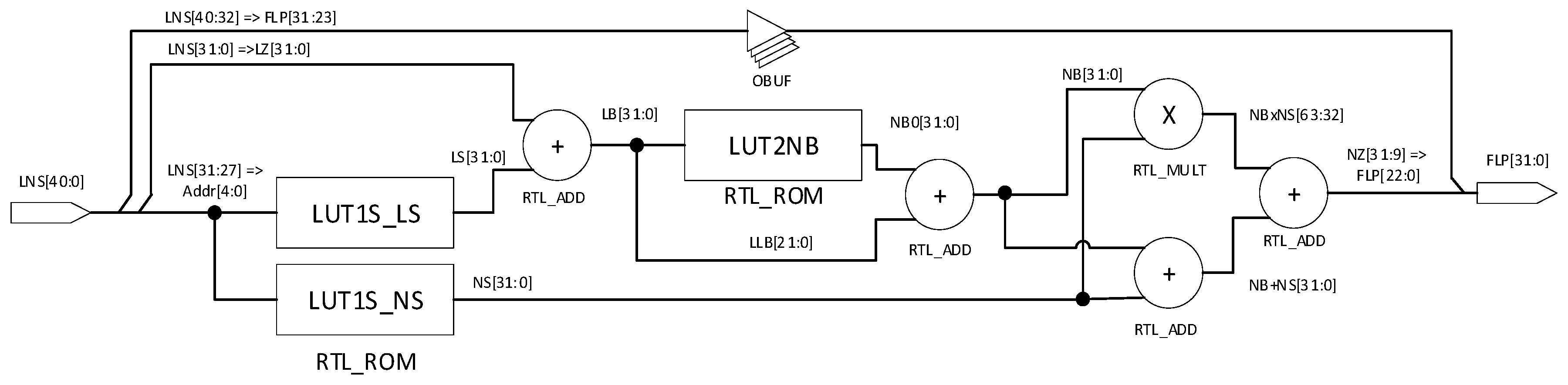
The structure of the LNS to FLP convertor represented by RTL (Register Transfer Level) is shown in Figure 4. The design is based on the algorithm of RISC conversion from LNS to FLP as described in Section 3. The sign bit and the integer part of the LNS input are directly connected to the sign and exponent parts of the FPL output. The fractional part of the input signal is marked as LZ. The five MSB bits of LZ are the input for Table 3, LUT1LS (Address column). LB described in (15) is computed as a sum of LUT1LS output LS and the signal LZ. In this converter design, only a simple approximation according to (22) is realized. LB is calculated as the sum of NB0 and LLB. The mantissa NZ (18) as a part of the output FLP number is computed as the sum of three signals: NB, NS, and output product of NB and NS. Division in (18) is realized by a proper choice of the output product bits.
Both tables LUT1LS and LUT2NB at the RTL level are implemented as an ROM memory. After performing the synthesis and implementation steps in Vivado IDE, the tables are assigned to the LUT tables [28] of FPGA. In FPGAs, LUT tables are part of configuration blocks and are the main resource for implementation of combinational logic. Multiplication and summation operations are automatically assigned to DSP cores [29]. The overall converter design needs only 50 slices representing just 0.32% of the used FPGA chip capacity. In Table 5, the obtained results are compared with the reference conventional approximation methods [6] and very fast shift-and-add methods [20]. Latency of the circuit, or the time from input to output as a performance measure, is very circuit-dependent. In the considered reference design, the FPGA Virtex II was used, which is an older product line of the Xilinx FPGA chips.
Previous converters are realized on 65 nm full customizable CMOS technology with latency under 1 ns [20]. For our implementation, a 28-nm prefabricated structure of FPGA Artix-7 was used. Even with this significant limitation, the achieved latency was 22.198 ns (12.083-ns logic delay and 10.115 net delay), which is a very promising result for the embedded real-time applications.
6.2. Simulation and Verification
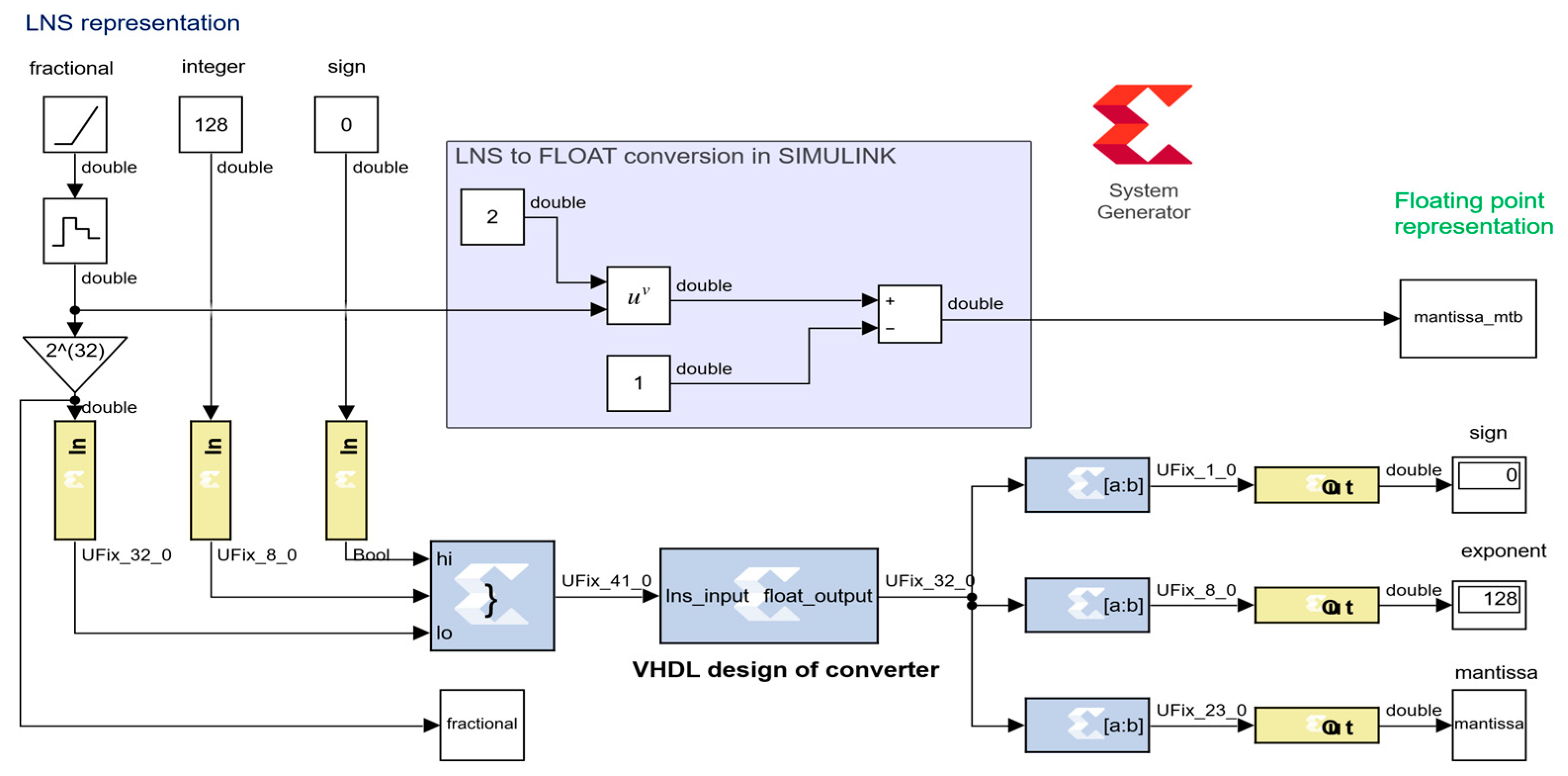
For synthesis, simulation, and verification of the presented converter design, the Matlab–Simulink environment combined with the system generator toolbox [30] were used. The system generator toolbox is an additional part of Vivado IDE connecting synthesis and simulation tools of digital designs targeted for FPGA with Matlab–Simulink. After a successful installation of both environments, it is possible to add system generator blocks to the Simulink simulation scheme. These blocks are not simulated in the Matlab environment but separately in the Vivado simulator. The simulation scheme is shown in Figure 5. Specialized input and output blocks serve as an interface between Matlab and Vivado simulation tools. This approach is more flexible than a standard testbench created in Vivado IDE.
The core of the simulation scheme is the system generator block, which represents the VHDL code of the converter developed in Vivado IDE. The output signal from the converter is split into the sign, exponent, and mantissa parts. For verification, the mantissa signal simulated in Vivado using system-generator-for-DSP blocks and the mantissa_mtb obtained directly in Simulink were compared. The mantissa error was calculated as the difference between the mantissa and the mantissa_mtb.
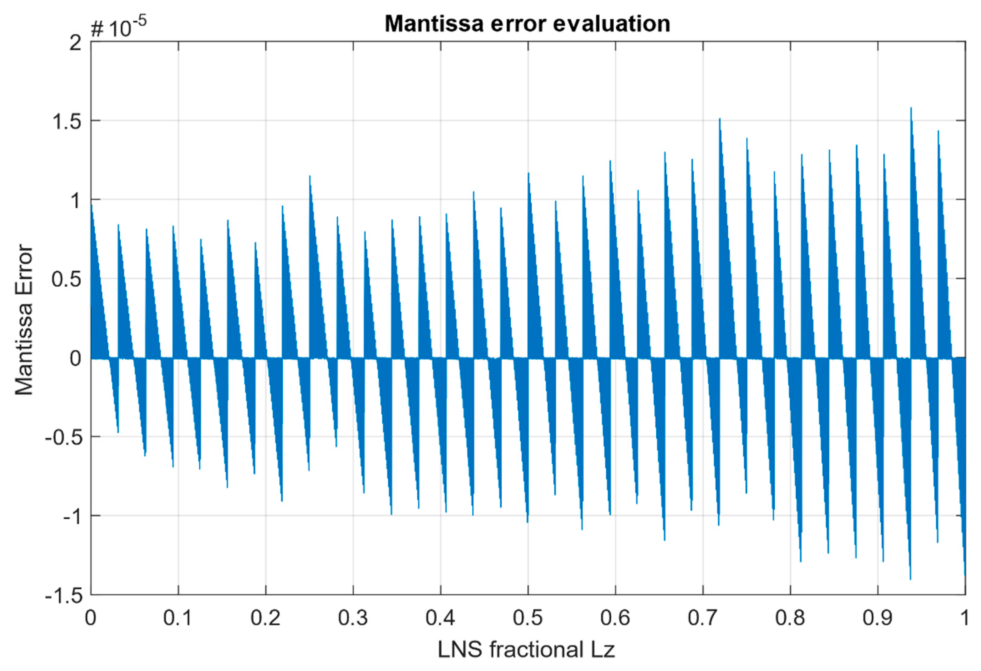
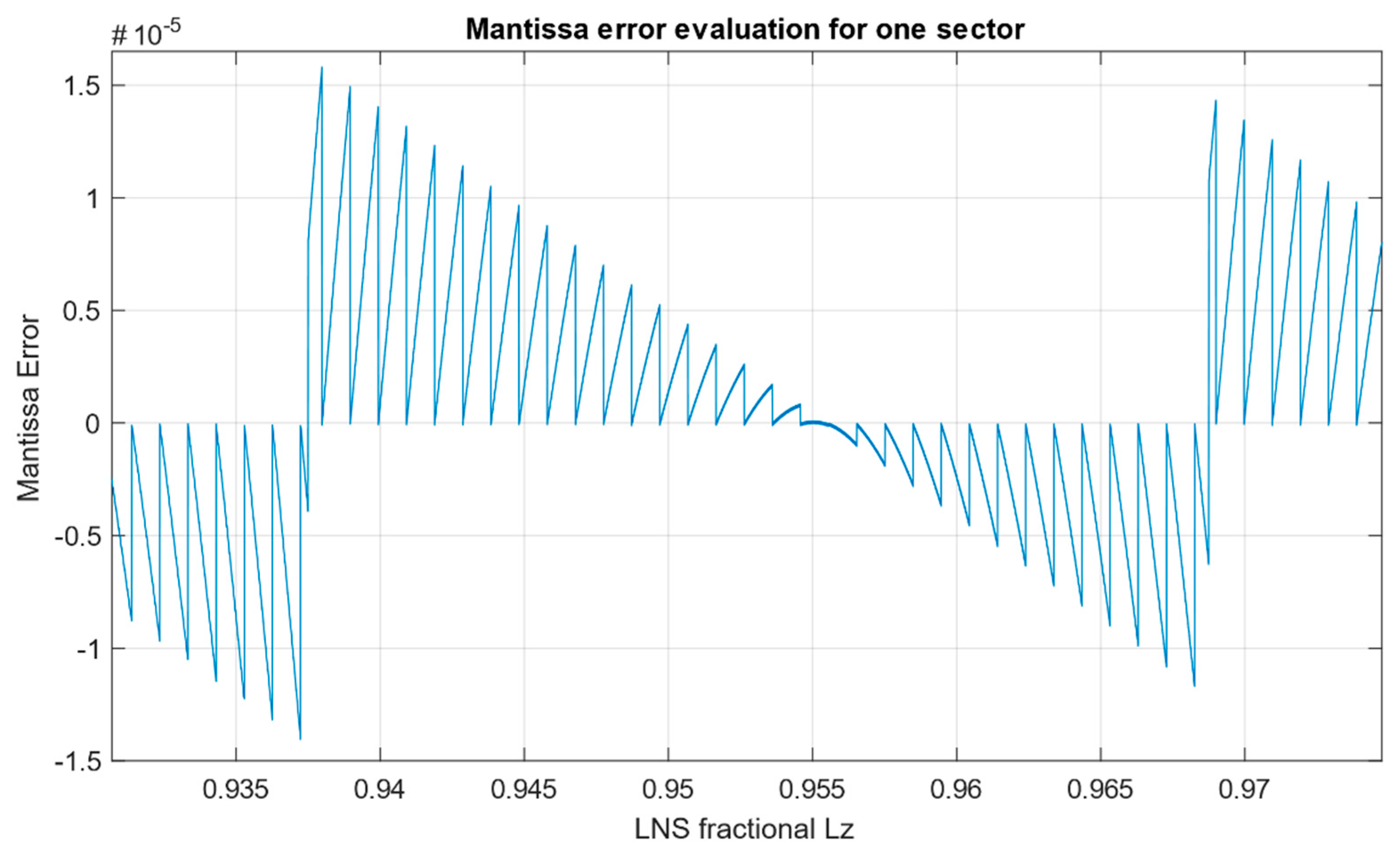
From the simulated fractional input in the interval 〈〉, the maximum positive mantissa error is and the maximum negative mantissa error is , which corresponds to the maximum error as mentioned in Section 4. The average error across the input range is . Overall dependence of the conversion error on the fractional part LZ is depicted in Figure 6. Dependence of the error focused for one sector on Address 30 in Table 3 is shown in Figure 7.
In Table 6, accuracy achieved using the proposed LiS method of LNS to FPL converter was compared with selected existing methods.
It can be observed that the proposed converter has a much better accuracy compared with other presented converters.
The proposed looping-in-sectors (LiS) method can be included in a category in between the approximation methods and the shift-and-add methods, which are very fast and ROM-less, based only on logic circuits and binary operations. The proposed LiS method uses a very simple approximation at the bit-manipulation level, a simple so-called RISC operation, and needs relatively small memory (32 + 40 memory cells).
The advantage of the proposed LiS method over the shift-and-add methods is a much higher relative accuracy (up to 1000 times), the disadvantage is a higher latency. Compared to conventional approximation methods, its advantages are simplicity and a higher speed.
7. Discussion
Conversions of numbers play an important role in the LNS arithmetic, especially in real-time systems. In this paper, equivalence between the FLP (semi-logarithmic) and LNS (fully logarithmic) systems was defined, and conversion between them was reduced to a conversion between the mantissa and fraction performed within the interval 〈1, 2〉. Derived correction functions enabled to specify an optimal interval for conversion within the plateau around their maxima where a mathematically simple and accurate interpolation can be performed. According to the developed procedure called looping in sectors (LiS), the converted number is to be moved to the plateau in the vicinity of the correction function peak and back after the interpolation accomplishment, hence reducing memory consumption. Note, that the LiS is performed without loss of accuracy, resulting in effective RISC conversions, which use only elementary computer operations. The developed conversions are then implemented in the designed LNS addition based on RISC operations and can thus be realized without a necessity to use multiplication, division, and other functions.
As a part of the development, conversion algorithms from LNS to FLP and vice versa [25] were implemented on FPGA, and their accuracy was verified by simulation. The presented methodology based on the new correction functions, the looping-in-sectors method, and the optimal choice of a base for an efficient interpolation can further be optimized for different types of applications in embedded systems. For different applications, different attributes are prioritized: in measurement and signal processing from sensors it is accuracy, in complex control algorithms it is speed, in automotive and autonomous systems reliability and credibility of the information obtained are the most essential ones.
The modern very fast “shift-and-add” methods (latencies about 1 ns) prevail only in selected complex algorithms that tolerate low accuracy (only 1%) but are inappropriate in other applications. The proposed LiS method is suitable for control applications in combination with input and output signal processing, as well as one of alternative methods for redundant signal processing and fault-detection due to a deterministically determined high accuracy. The proposed LiS method belongs to faster methods (with a latency of 22 ns) and can be used in real-time control applications even in time-critical applications with a sampling period up to 1 ms.
The future research will be directed on the functional safety of embedded system applications, usually implemented through redundancy and dual-channel technology today. In this sense, we understand LNS not only as an alternative to FLP but also as an SW/HW independent dual method of calculation to eliminate errors and increase the plausibility of results in full compliance with a new paradigm [34]: “It is much more important to know whether information is reliable or not than the accuracy of the information itself.”
Author Contributions
Conceptualization, P.D. and O.H.; methodology, P.D.; software, M.K. and E.K.; validation, P.D., M.K. and E.K.; formal analysis, P.D.; investigation, P.D.; resources, M.K.; writing—original draft preparation, P.D.; writing—review and editing, P.D., M.K., and A.K.; supervision, O.H.; project administration, A.K.; funding acquisition, P.D. and A.K. All authors have read and agreed to the published version of the manuscript.
Funding
This research was funded by the SLOVAK RESEARCH AND DEVELOPMENT AGENCY, grant No. APVV-17-0190 and the SLOVAK CULTURAL EDUCATIONAL GRANT AGENCY, grant No. 038STU-4/2018.
Acknowledgments
The paper was partially supported by the Slovak Research and Development Agency, grant No. APVV-17-0190 and the Slovak Cultural Educational Grant Agency, grant No. 038STU-4/2018.
Conflicts of Interest
The authors declare no conflict of interest.
References
- Lee, B.R. A Comparison of Logarithmic and Floating Point Number Systems Implemented on Xilinx Virtex-II Field Programmable Arrays. Ph.D. Thesis, Cardiff University, Cardiff, UK, 2004. [Google Scholar]
- Chugh, M.; Parhami, M. Logarithmic arithmetic as an alternative to floating-point: A review. In Proceedings of the 2013 Asilomar Conference on Signals, Systems and Computers, Pacific Grove, CA, USA, 3–6 November 2013; pp. 1139–1143. [Google Scholar] [CrossRef] [Green Version]
- Kingsbury, N.G.; Rayner, P.J.W. Digital filtering using logarithmic arithmetic. Electron. Lett. 1971, 7, 56–58. [Google Scholar] [CrossRef]
- Swartzlander, E.E.; Alexopoulos, A.G. The Sign/Logarithm Number System. IEEE Trans. Comput. 1975, 24, 1238–1242. [Google Scholar] [CrossRef]
- Arnold, M.G. A VLIW architecture for logarithmic arithmetic. In Proceedings of the Euromicro Symposium on Digital System Design, Belek-Antalya, Turkey, 1–6 September 2003; pp. 294–302. [Google Scholar] [CrossRef]
- Haselman, H.M.; Beau champ, M.; Wood, A.; Hauck, S.; Underwood, K.; Hemmert, K.S. A comparison of floating point and logarithmic number systems for FPGAs. In Proceedings of the 13th Annual IEEE Symposium on Field-Programmable Custom Computing Machines (FCCM’05), Napa, CA, USA, 18–20 April 2005; pp. 181–190. [Google Scholar] [CrossRef]
- Kouretas, I.; Paliouras, V. Logarithmic number system for deep learning. In Proceedings of the 2018 7th International Conference on Modern Circuits and Systems Technologies (MOCAST), Thessaloniki, Greece, 7–9 May 2018; pp. 1–4. [Google Scholar] [CrossRef]
- Juang, T.; Lin, C.; Lin, G. Design of High-Speed and Area-Efficient Cartesian to Polar Coordinate Converters Using Logarithmic Number Systems. In Proceedings of the 2019 International SoC Design Conference (ISOCC), Jeju, Korea, 6–9 October 2019; pp. 180–181. [Google Scholar] [CrossRef]
- Garcia, J.; Arnold, M.G.; Bleris, L.; Kothare, M.V. LNS architectures for embedded model predictive control processors. In Proceedings of the 2004 International Conference on Compilers, Architecture, and Synthesis for Embedded Systems (CASES ’04), New York, NY, USA, 7–16 September 2004; pp. 79–84. [Google Scholar] [CrossRef] [Green Version]
- Arnold, M.G.; Collange, S. The Denormal Logarithmic Number System. In Proceedings of the 2013 IEEE 24th International Conference on Application-Specific Systems, Architectures and Processors, Washington, DC, USA, 5–7 June 2013; pp. 117–124. [Google Scholar] [CrossRef] [Green Version]
- Juang, T.; Meher, P.K.; Jan, K. High-performance logarithmic converters using novel two-region bit-level manipulation schemes. In Proceedings of the 2011 International Symposium on VLSI Design, Automation and Test, Hsinchu, Taiwan, 25–28 April 2011; pp. 1–4. [Google Scholar] [CrossRef]
- Arnold, M.G.; Kouretas, I.; Paliouras, V.; Morgan, A. One-Hot Residue Logarithmic Number Systems. In Proceedings of the 2019 29th International Symposium on Power and Timing Modeling, Optimization and Simulation (PATMOS), Rhodes, Greece, 1–8 March 2019; pp. 97–102. [Google Scholar] [CrossRef]
- Zaghar, D.R. Design and Implementation of a High Speed and Low Cost Hybrid FPS/LNS Processor Using FPGA. J. Eng. Sustain. Dev. 2010, 14, 86–104. [Google Scholar]
- Naziri, S.Z.M.; Ismail, R.C.; Shakaff, A.Y.M. The design revolution of logarithmic number system architecture. In Proceedings of the 2nd International Conference on Electrical, Electronics and System Engineering (ICEESE), Kuala Lumpur, Malaysia, 8–9 November 2014; pp. 5–10. [Google Scholar] [CrossRef]
- Nam, B.; Kim, H.; Yoo, H. Power and Area-Efficient Unified Computation of Vector and Elementary Functions for Handheld 3D Graphics Systems. IEEE Trans. Comput. 2008, 57, 490–504. [Google Scholar] [CrossRef]
- Arnold, M.G.; Collange, S. A Real/Complex Logarithmic Number System ALU. IEEE Trans. Comput. 2011, 60, 202–213. [Google Scholar] [CrossRef]
- Abed, K.H.; Siferd, R.E. CMOS VLSI implementation of a low-power logarithmic converter. IEEE Trans. Comput. 2003, 52, 1421–1433. [Google Scholar] [CrossRef]
- Juang, T.; Chen, S.; Cheng, H. A Lower Error and ROM-Free Logarithmic Converter for Digital Signal Processing Applications. IEEE Trans. Circuits Syst. II Express Briefs 2009, 56, 931–935. [Google Scholar] [CrossRef]
- Kuo, C.; Juang, T. Area-efficient and highly accurate antilogarithmic converters with multiple regions of constant compensation schemes. Microsyst. Technol. 2018, 24, 219–225. [Google Scholar] [CrossRef]
- Nandan, D. An Efficient Antilogarithmic Converter by Using Correction Scheme for DSP Processor. Traitement du Signal 2020, 37, 77–83. [Google Scholar] [CrossRef]
- Chen, C.; Chow, P. Design of a versatile and cost-effective hybrid floating-point/LNS arithmetic processor. In Proceedings of the 17th ACM Great Lakes symposium on VLSI (GLSVLSI ’07), Stresa-Lago Maggiore, Italy, 11–13 March 2007; pp. 540–545. [Google Scholar] [CrossRef] [Green Version]
- Ismail, R.C.; Zakaria, M.K.; Murad, S.A.Z. Hybrid logarithmic number system arithmetic unit: A review. In Proceedings of the 2013 IEEE International Conference on Circuits and Systems (ICCAS), Kuala Lumpur, Malaysia, 18–19 September 2013; pp. 55–58. [Google Scholar] [CrossRef]
- Chen, C.; Tsai, T.C. Application-specific instruction design for LNS addition/subtraction computation on an SOPC system. In Proceedings of the 2009 6th International Conference on Electrical Engineering/Electronics, Computer, Telecommunications and Information Technology, Pattaya, Thailand, 6–9 May 2009; pp. 640–643. [Google Scholar] [CrossRef]
- Finnerty, A.; Ratigner, H. Reduce Power and Cost by Converting from Floating Point to Fixed Point—White Paper: Floating vs Fixed Point; Xilinx: San Jose, CA, USA, 2017. [Google Scholar]
- Drahos, P.; Kocur, M. Logarithmic addition and subtraction for embedded control systems. In Proceedings of the 2020 Cybernetics & Informatics: 30th International Conference, Velke Karlovice, Czech Republic, 29 January–1 February 2020. [Google Scholar] [CrossRef]
- Klimo, I.; Kocúr, M.; Drahoš, P. Implementation of logarithmic number system in control application using FPGA. In Proceedings of the 16th IFAC Conference on Programmable Devices and Embedded Systems (PDEeS´19), High Tatras, Slovak Republic, 29–31 October 2019. [Google Scholar] [CrossRef]
- Xilinx. 7 Series FPGAs Data Sheet: Overview. Xilinx. 2018. Available online: https://www.xilinx.com/support/documentation/data_sheets/ds180_7Series_Overview.pdf (accessed on 10 April 2020).
- Xilinx. 7 Series FPGAs Configurable Logic Block: User Guide. Xilinx. 2016. Available online: https://www.xilinx.com/support/documentation/user_guides/ug474_7Series_CLB.pdf (accessed on 10 April 2020).
- Xilinx. 7 Series DSP48E1 Slice: User Guide. Xilinx. 2018. Available online: https://www.xilinx.com/support/documentation/user_guides/ug479_7Series_DSP48E1.pdf (accessed on 10 April 2020).
- Xilinx. Vivado Design Suite User Guide: Model-Based DSP Design Using System Generator. Xilinx. 2019. Available online: https://www.xilinx.com/support/documentation/sw_manuals/xilinx2019_2/ug897-vivado-sysgen-user.pdf (accessed on 10 April 2020).
- Mitchell, J.N. Computer Multiplication and Division Using Binary Logarithms. IRE Trans. Electron. Comput. 1962, 11, 512–517. [Google Scholar] [CrossRef]
- Combet, M.; Zonneveld, H.V.; Verbeek, L. Computation of the base two logarithm of binary numbers. IEEE Trans. Electron. Comput. 1965, 14, 863–867. [Google Scholar] [CrossRef]
- SanGregory, S.L.; Siferd, R.E.; Brother, C.; Gallagher, D. A fast, low-power logarithm approximation with CMOS VLSI implementation. In Proceedings of the 42nd IEEE Midwest Symposium on Circuits and Systems (MWSCAS), Las Cruces, NM, USA, 8–11 August 1999; Volume 1, pp. 388–391. [Google Scholar] [CrossRef]
- The European Safety Critical Applications Positioning Engine (ESCAPE). GSA/GRANT/02/2015. Available online: http://www.gnss-escape.eu/ (accessed on 15 June 2020).
Figure 1.
Diagram of correction functions from NZ to LZ (red plot) and from LZ to NZ (blue plot) for .
Figure 1.
Diagram of correction functions from NZ to LZ (red plot) and from LZ to NZ (blue plot) for .

Figure 2.
Looping in sectors: conversion from LZ to NZ for .

Figure 3.
Principle of approximating NB using a simple bit manipulation.

Figure 4.
Illustration of the principle of approximating NB using a simple interpolation.

Figure 5.
Converter simulation and verification in the Matlab–Simulink environment.

Figure 6.
Mantissa error evaluation.

Figure 7.
Zoomed mantissa error evaluation for one sector.


Table 1.
Floating point (FLP) number representation.
| Sign Bit | Exponent: e-Bits | Mantissa: t-Bits |
|---|---|---|
| S | E | m = N/M |
Table 2.
Logarithmic number (LNS) representation.
| Sign Bit | Integer: e-Bits | Fractional: t-Bits |
|---|---|---|
| S | E | f = F/M |
Table 3.
Look-up table LUT1LS for 32 sectors.
| Min Lz | Max Lz | Address | Ns | Ls |
|---|---|---|---|---|
| 0 | 31 | 0 | −304 | 520.3424 |
| 32 | 63 | 1 | −290 | 491.8925 |
| … | … | … | … | … |
| 480 | 511 | 15 | −32 | 46.9030 |
| 512 | 543 | 16 | −8 | 11.5869 |
| 544 | 575 | 17 | 12 | −17.2117 |
| 576 | 607 | 18 | 36 | −51.0449 |
| … | … | … | … | … |
| 960 | 991 | 30 | 352 | −436.4951 |
| 992 | 1023 | 31 | 380 | −466.2551 |
Table 4.
Generating Ns using 3 active bits in 32 sectors.
| |NS|\w Bits | 8 | 7 | 6 | 5 | 4 | 3 | 2 | 1 |
|---|---|---|---|---|---|---|---|---|
| 304 | 1 | 0 | 1 | 0 | −1 | 0 | 0 | 0 |
| 290 | 1 | 0 | 0 | 1 | 0 | 0 | 0 | 1 |
| … | … | … | … | … | … | … | … | … |
| 32 | 0 | 0 | 0 | 1 | 0 | 0 | 0 | 0 |
| 8 | 0 | 0 | 0 | 0 | 0 | 1 | 0 | 0 |
| 12 | 0 | 0 | 0 | 0 | 0 | 1 | 1 | 0 |
| 36 | 0 | 0 | 0 | 1 | 0 | 0 | 1 | 0 |
| … | … | … | … | … | … | … | … | … |
| 352 | 1 | 1 | 0 | −1 | 0 | 0 | 0 | 0 |
| 380 | 1 | 1 | 0 | 0 | 0 | 0 | −1 | 0 |
Table 5.
Comparison of area, latency, and accuracy of a conversion from LNS to FLP.
| Conventional Design [6] | Proposed Design | Shift-and-Add Design [20] | |
|---|---|---|---|
| Slices | 236 | 50 | NA |
| Multipliers | 20 | 1 | 0 |
| Memory | 4 × 18 k BRAM | 0 | 0 |
| Latency | 72 ns | 22/12 ns | <1 ns |
| Accuracy | High | <0.001% | >1% |
Table 6.
Comparison of accuracies achieved using the proposed LiS method with selected conversion methods.
Table 6.
Comparison of accuracies achieved using the proposed LiS method with selected conversion methods.
| Maximum Positive Error | Maximum Negative Error | Error Range | Maximum Positive Relative Error | Maximum Negative Relative Error | Relative Error Range | |
|---|---|---|---|---|---|---|
| Mitchell [31] | 0.086 | 0 | 0.086 | 5.791% | 0 | 5.791% |
| Combet [32] | 0.0253 | −0.0062 | 0.0315 | 2.293% | −0.468% | 2.761% |
| SG [33] | 0.0292 | −0.028 | 0.0572 | 2.503% | −1.704% | 4.207% |
| Juang [18] | 0.0369 | −0.0097 | 0.0466 | 2.963% | −0.487% | 3.45% |
| Juang [11] | 0.0319 | 0 | 0.0319 | 2.337% | 0 | 2.337% |
| AS [17] | NA | NA | NA | 1.331% | −0,5631% | 1,8941% |
| Kuo [19] | NA | NA | NA | 1.2% | −0.1436% | 1.3436% |
| Nandan [20] | NA | NA | NA | 0.94% | −0.1436% | 1.084% |
| Chen [23] | NA | NA | NA | NA | NA | 0.138% |
| LiS method | 0.00001581 | −0.00001407 | 0.00002988 | 0.000966% | −0.000783% | 0.001749% |
© 2020 by the authors. Licensee MDPI, Basel, Switzerland. This article is an open access article distributed under the terms and conditions of the Creative Commons Attribution (CC BY) license (http://creativecommons.org/licenses/by/4.0/).
Share and Cite
MDPI and ACS Style
Drahoš, P.; Kocúr, M.; Haffner, O.; Kučera, E.; Kozáková, A. RISC Conversions for LNS Arithmetic in Embedded Systems. Mathematics 2020, 8, 1208. https://0-doi-org.brum.beds.ac.uk/10.3390/math8081208
AMA Style
Drahoš P, Kocúr M, Haffner O, Kučera E, Kozáková A. RISC Conversions for LNS Arithmetic in Embedded Systems. Mathematics. 2020; 8(8):1208. https://0-doi-org.brum.beds.ac.uk/10.3390/math8081208
Chicago/Turabian StyleDrahoš, Peter, Michal Kocúr, Oto Haffner, Erik Kučera, and Alena Kozáková. 2020. "RISC Conversions for LNS Arithmetic in Embedded Systems" Mathematics 8, no. 8: 1208. https://0-doi-org.brum.beds.ac.uk/10.3390/math8081208
Note that from the first issue of 2016, this journal uses article numbers instead of page numbers. See further details here.