
Combination Effect of Baffle Arrangement and Hybrid Nanofluid on Thermal Performance of a Shell and Tube Heat Exchanger Using 3-D Homogeneous Mixture Model


Abstract
:1. Introduction
2. Numerical Model
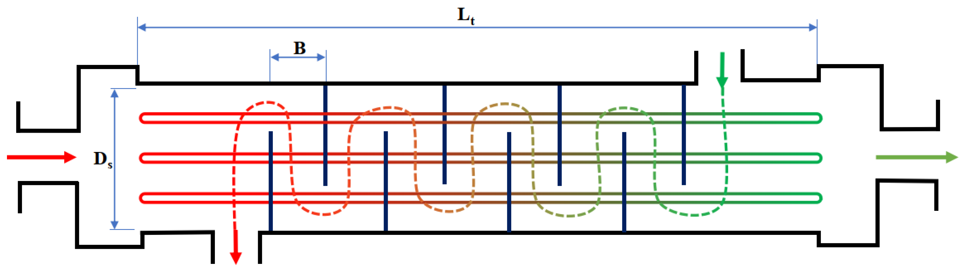
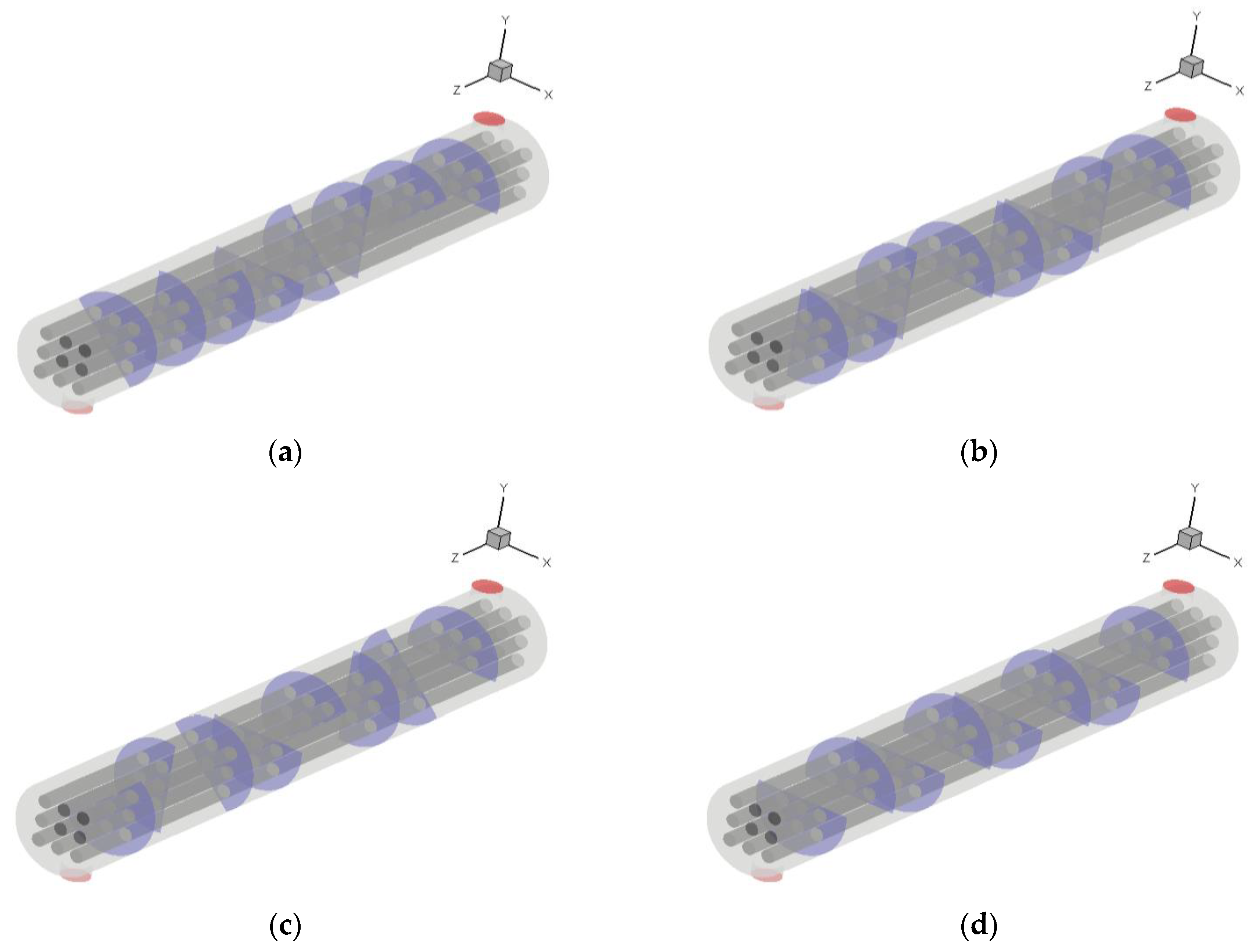
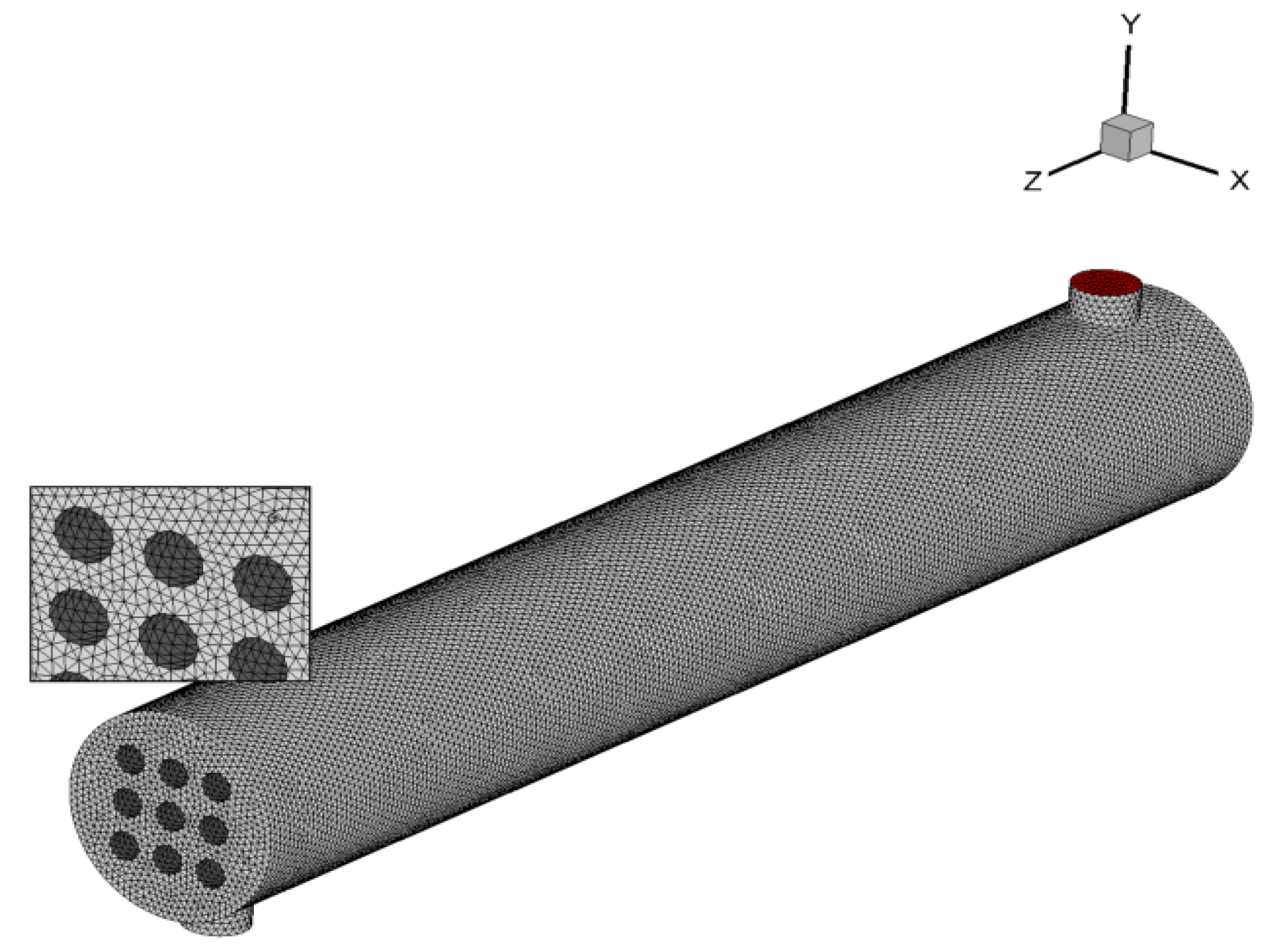
2.1. Physical Model
- The shell walls were insulated and assumed to be adiabatic.
- The gravity force was negligible.
- Nanofluid characteristics changes by temperature and the concentrations varied from 0 to 0.1%.
- Nanofluids represent Newtonian behavior.
- The nanomaterials were completely dispersed in base fluid and move with the same velocity as the fluid.
- The fluid flows in shell and tube sides were incompressible and fully developed. The modelings were done in the time-dependant (unsteady) conditions, but the results were reported a long time after the initial process when the results were steady (time-independent).
- Inlet temperature of water and Reynolds numbers were set at Tw,in = 293 K and Re = 10,000, 15,000, and 20,000.
- A pressure outlet was chosen for the water outlet.
2.2. Governing Equations
2.3. Thermophysical Characteristics of Hybrid Nanofluid
2.4. Numerical Procedure
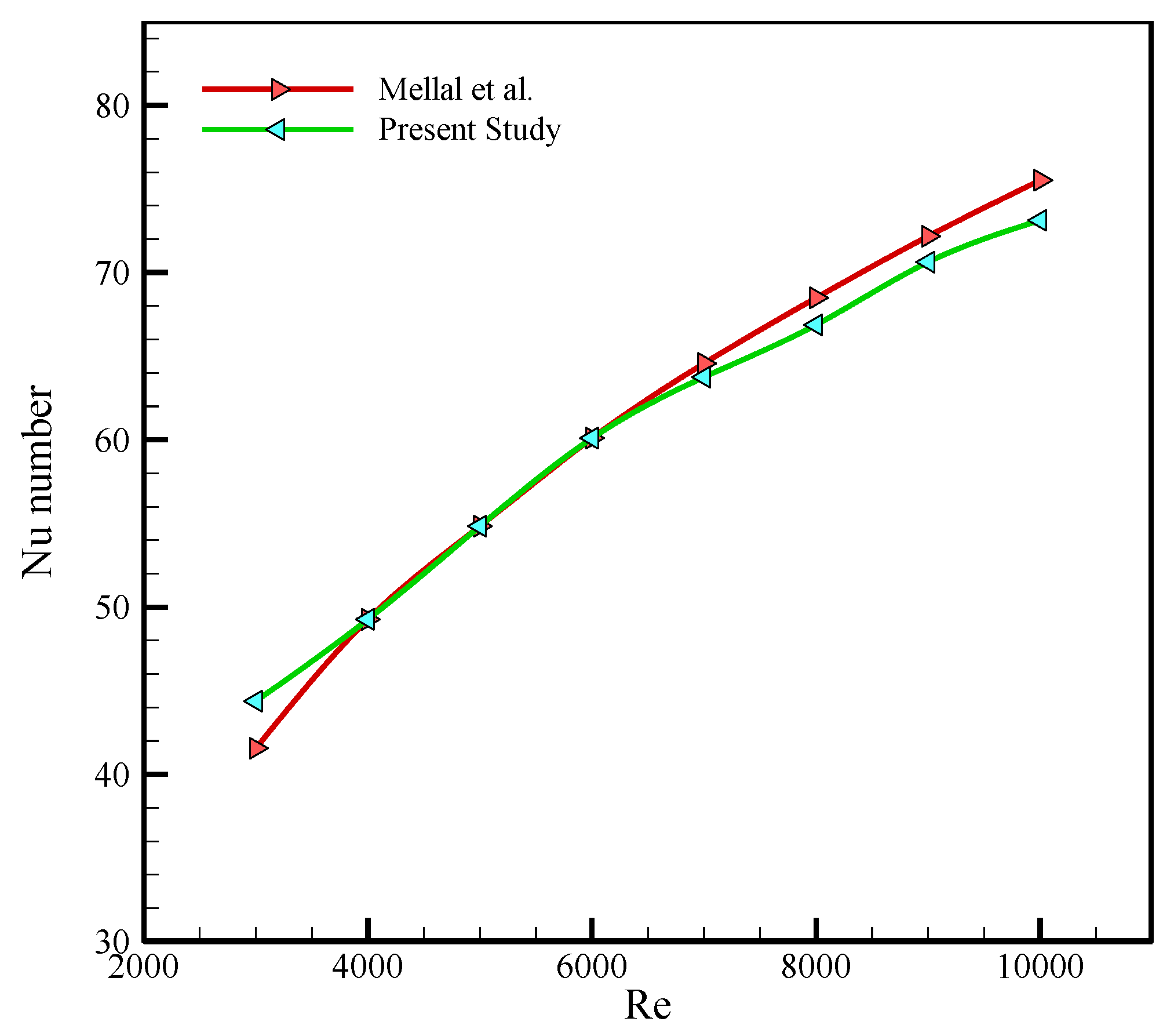
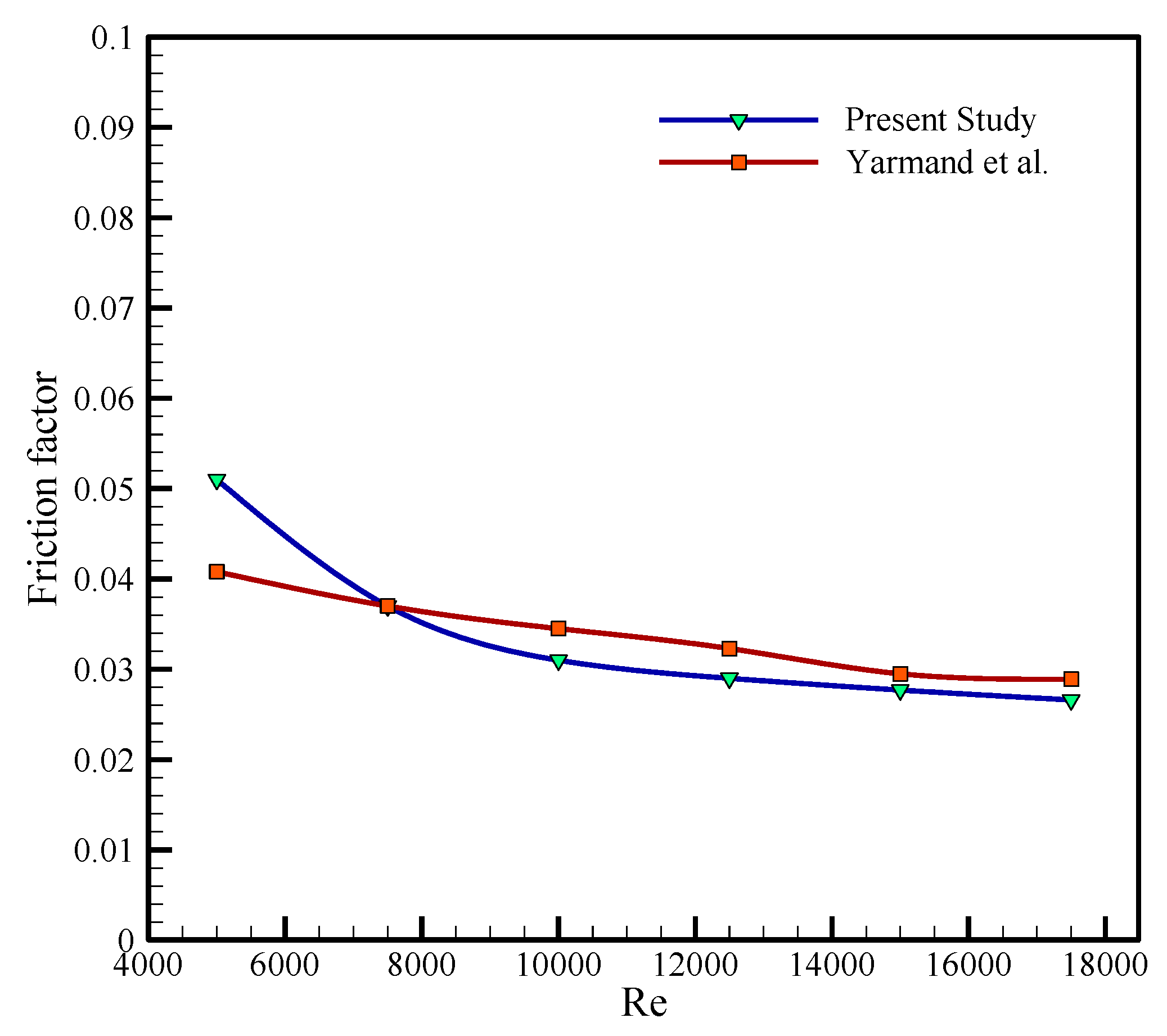
2.5. Model Validation
2.6. Grid Independence Study
3. Result and Discussion
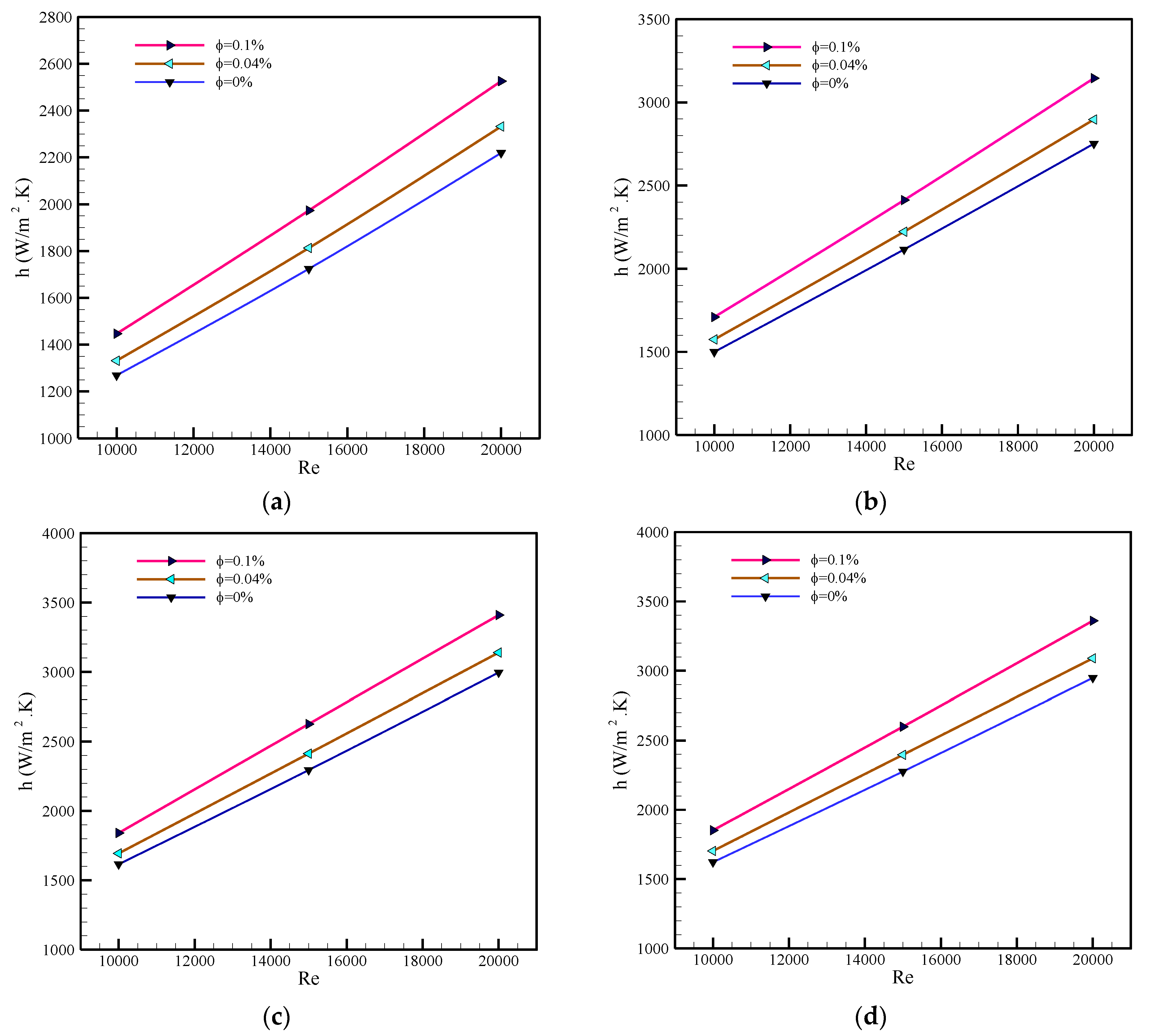
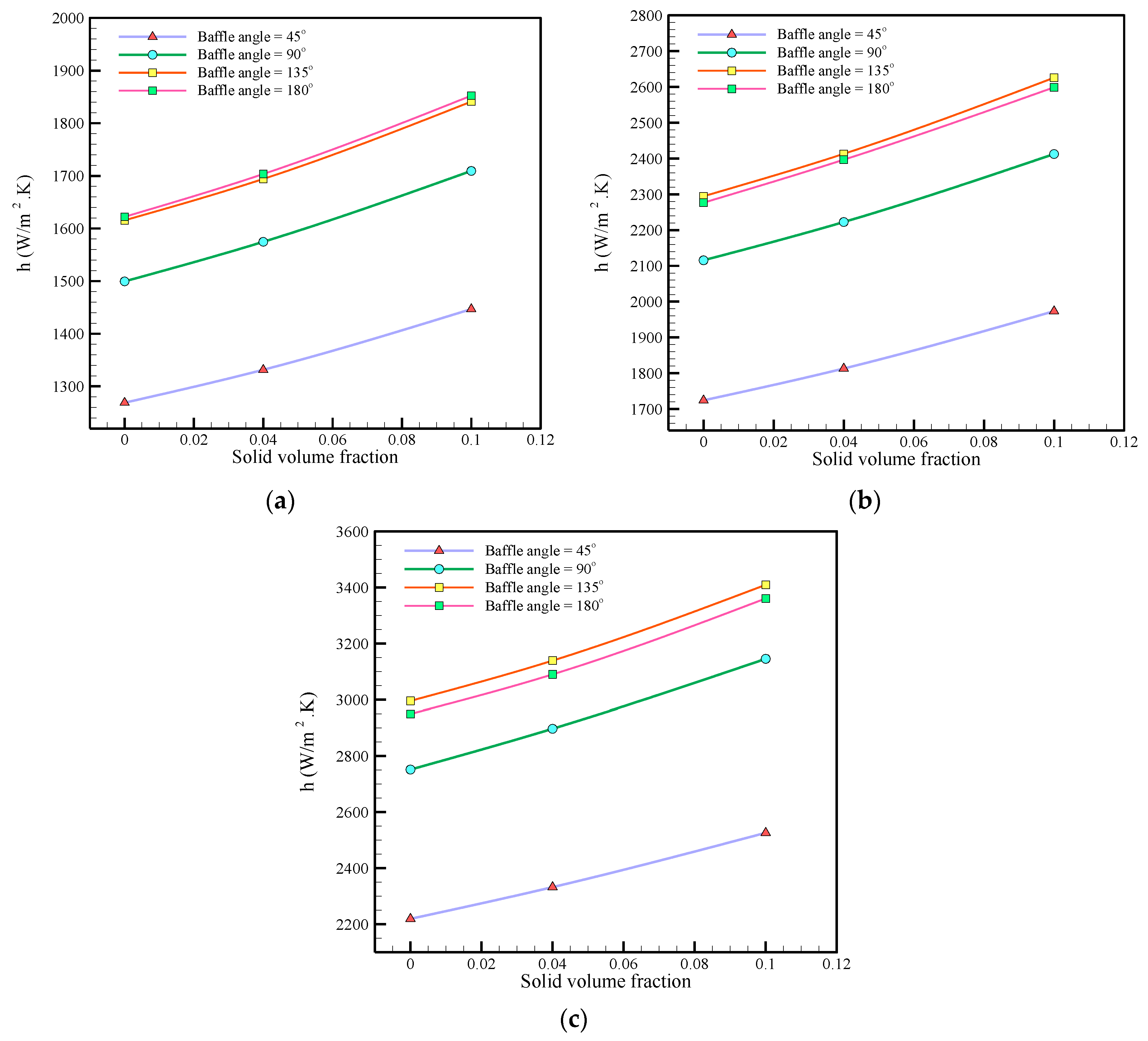
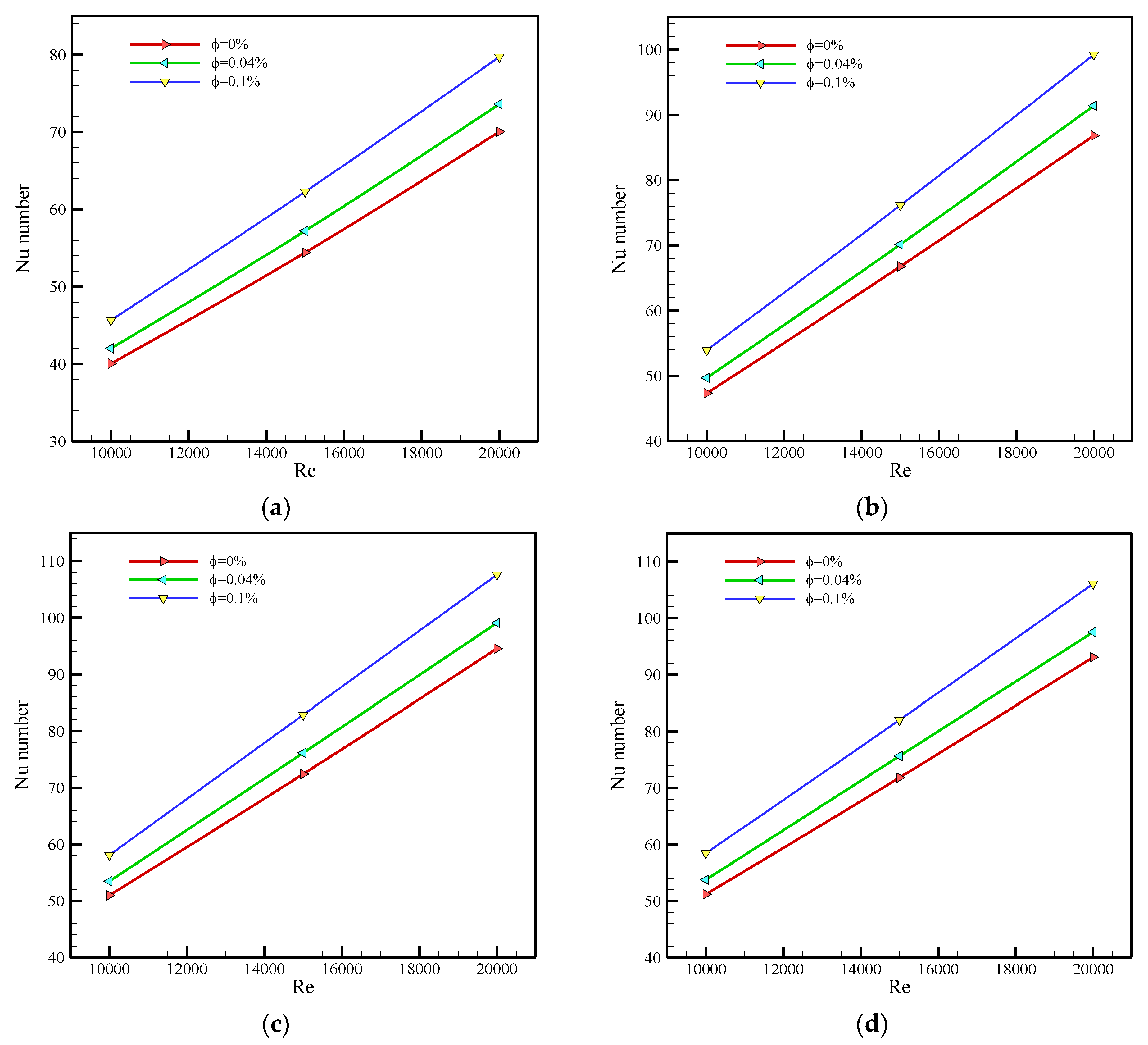
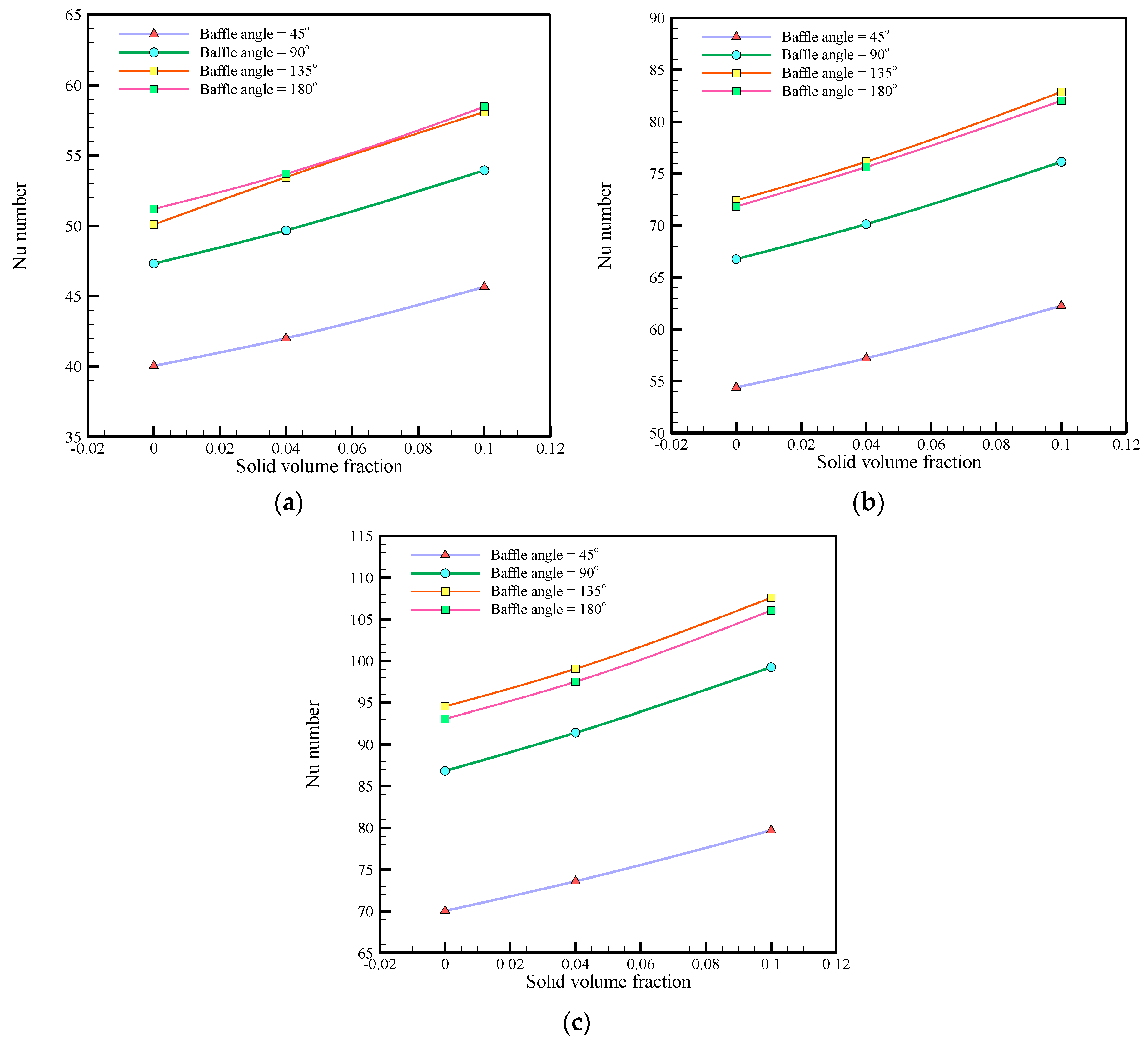
3.1. Heat Transfer Performance
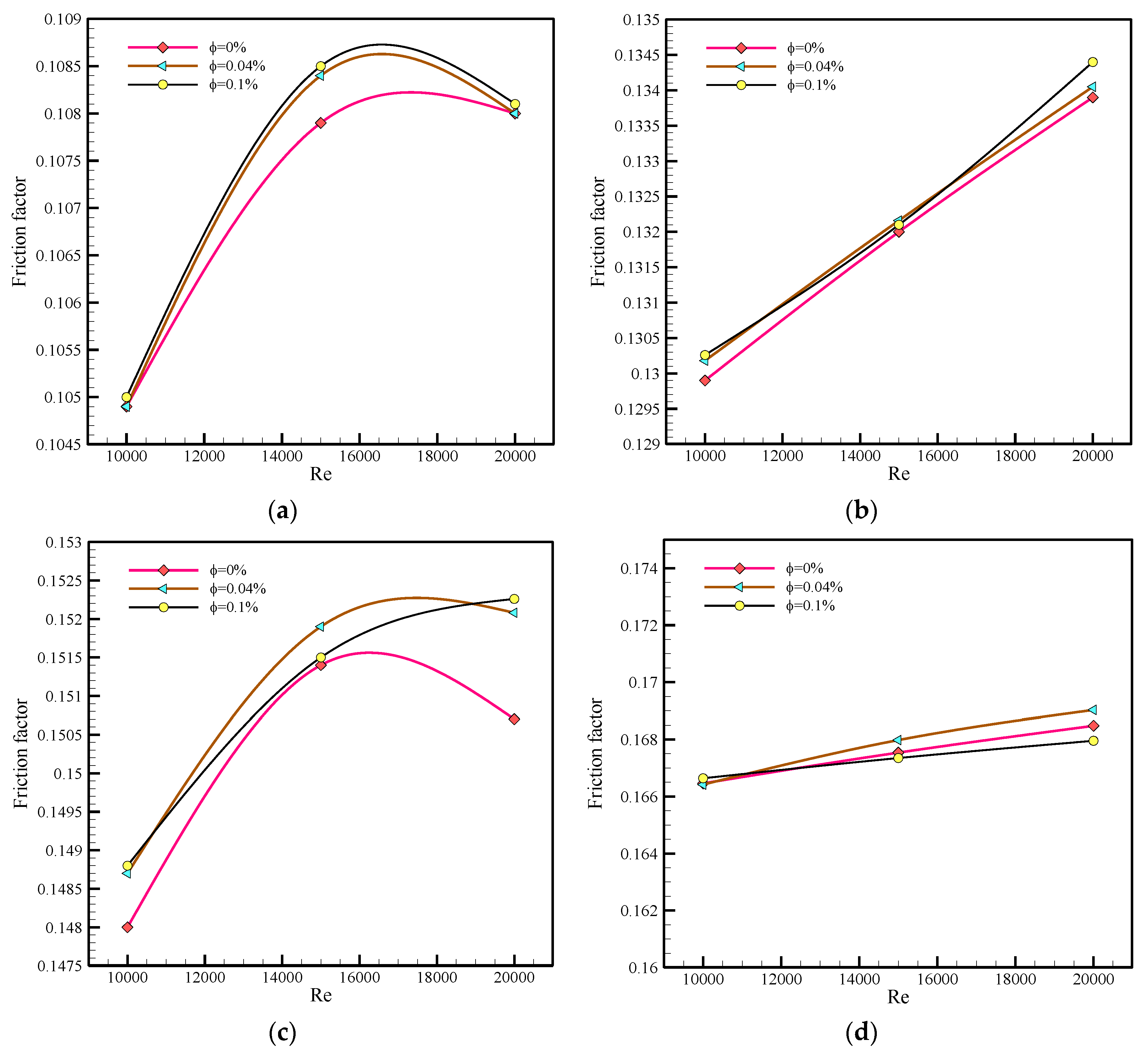
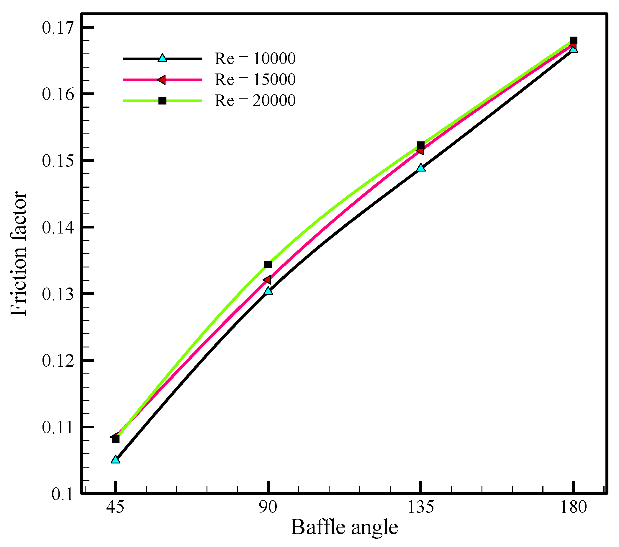
3.2. Friction Factor
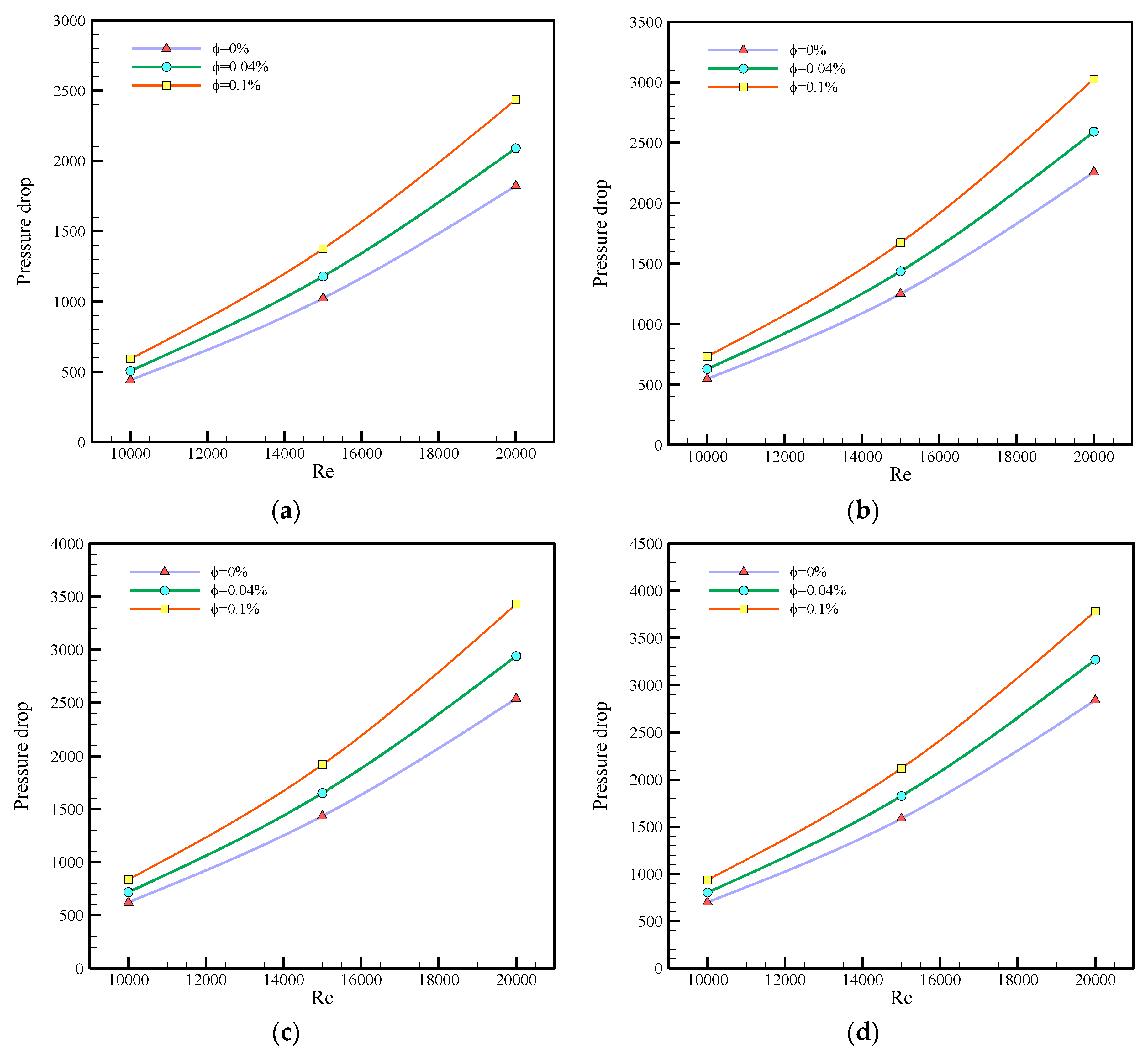
3.3. Pressure Drop
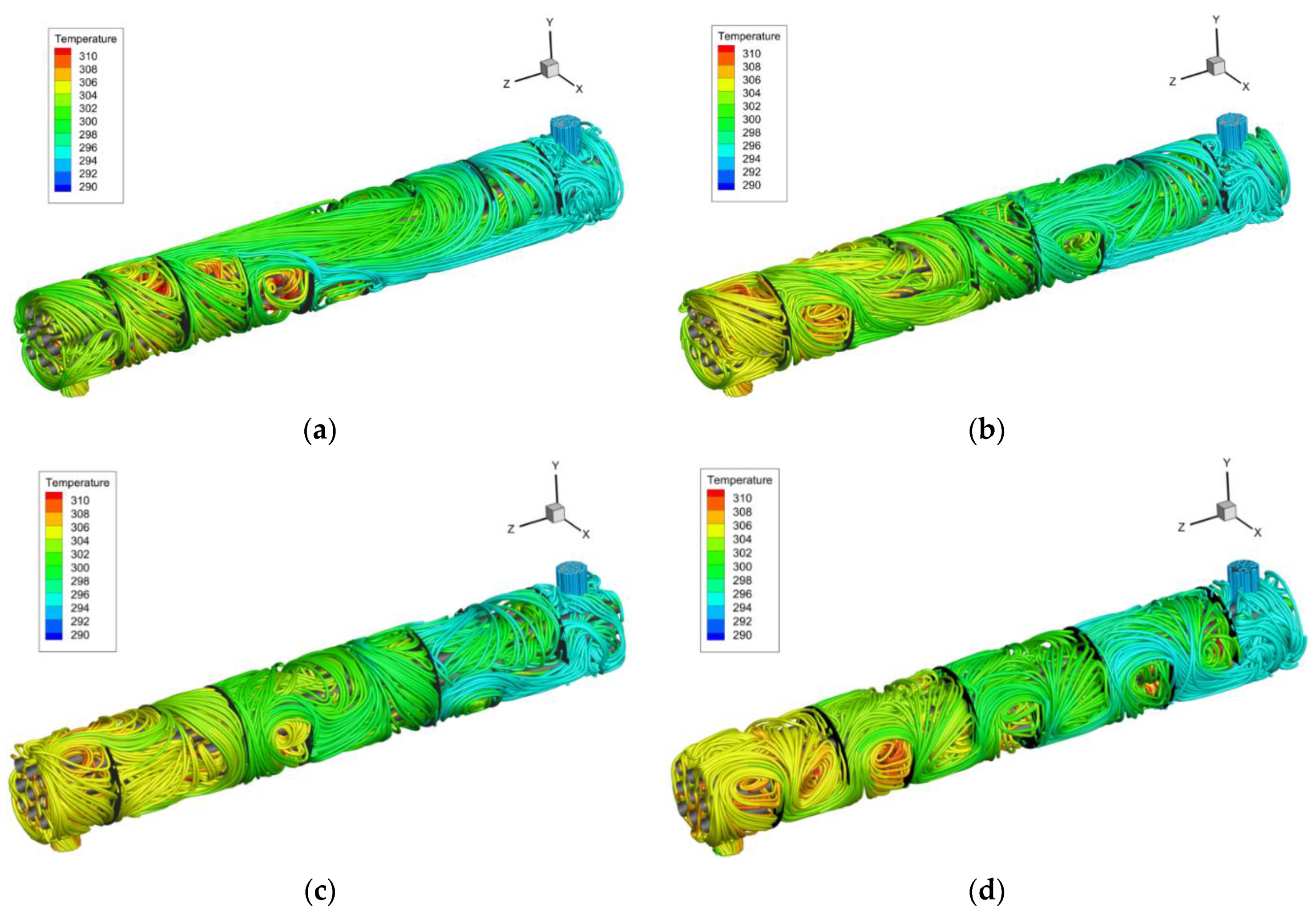
3.4. Temperature Streamline Contours
4. Conclusions
- (1)
- Having a higher viscosity than the base fluid, nanofluid could enhance the Nusselt number of the heat exchanger. Additionally, by increasing the baffle angle from 45° to 180°, the Nusselt number was enhanced. However, the Nu values of 135° and 180° were relatively the same at low Re numbers. At high Re numbers, the calculated Nu corresponding to baffles angle of 135° were higher.
- (2)
- At Re = 20,000, it was identified that heat exchangers with larger baffle angles could have higher resistance against fluid flow. Thus, the friction factor and, as a result, the value of the pressure drop was augmented.
- (3)
- It was identified that using nanofluid could create more pressure drop in comparison with the distilled water. However, this augmentation was compensated by improving the Nusselt number and the system’s heat transfer coefficient. However, a techno-economic analysis will identify the economic viability of using nanofluids in the heat exchanger.
- (4)
- By investigating the spatial temperature distribution along the shell side, it was identified that the optimum baffle angle of 135° could provide the highest thermal performance, uniform temperature outlet and the highest Nusselt number.
Author Contributions
Funding
Institutional Review Board Statement
Informed Consent Statement
Data Availability Statement
Conflicts of Interest
Nomenclature
| x, y, z | Cartesian coordinates (m) |
| Gravitational acceleration (m s−2) | |
| Mean velocity (m s−1) | |
| n | Number of phases |
| Nu | Nusselt number |
| Pr | Prandtl number |
| P | Pressure (N m−2) |
| u, v | Velocity components (m s−1) |
| Re | Reynolds number |
| hk | Sensible enthalpy for phase k (J Kg−1) |
| Cp | Specific heat capacity (J kg−1 K−1) |
| T | Temperature (K) |
| t | Time (s) |
| k | Thermal conductivity (W m−1 K−1) |
| K | Turbulent kinetic energy (m2 s−1) |
| Kt | Turbulent thermal conductivity (W m−1 K−1) |
| Velocity (m s−1) | |
| A0 | Shell wall area (m2) |
| m | Mass flow rate (kg s−1) |
| LMTD | The logarithmic mean temperature difference |
| h | Heat transfer coefficient (W m−2 K−1) |
| De | Hydraulic diameter (m) |
| Pt | Tube pitch (m) |
| D | Diameter (m) |
| L | Length (m) |
Greek Symbols
| Density (kg m−3) | |
| ε | Dissipation rate of Turbulent Kinetic Energy (m2 s−3) |
| Dynamic Viscosity (Pa s) | |
| Kinematic Viscosity (m2 s−1) | |
| Turbulent Eddy Viscosity (m2 s−1) | |
| Volume Fraction of Nanoparticles |
Subscripts
| eff | Effective |
| Z | Indices |
| m | Mixture |
| t | Turbulent |
| w | Wall |
| in | Inlet |
| out | Outlet |
| s | Shell |
| min | Minimum |
| max | Maximum |
References
- Sarafraz, M.M.; Tian, Z.; Tlili, I.; Kazi, S.; Goodarzi, M. Thermal evaluation of a heat pipe working with n-pentane-acetone and n-pentane-methanol binary mixtures. J. Therm. Anal. Calorim. 2020, 139, 2435–2445. [Google Scholar] [CrossRef]
- Benabderrahmane, Y.; Pain, J.-P. Thermal behaviour of a solid/liquid mixture in an ohmic heating sterilizer-slip phase model. Chem. Eng. Sci. 2000, 55, 1371–1384. [Google Scholar] [CrossRef]
- Chou, T.S.; Worley, F.L., Jr.; Luss, D. Local particle-liquid mass transfer fluctuations in mixed-phase cocurrent downflow through a fixed bed in the pulsing regime. Ind. Eng. Chem. Fundam. 1979, 18, 279–283. [Google Scholar] [CrossRef]
- Safaei, M.R.; Safdari Shadloo, M.; Goodarzi, M.S.; Hadjadj, A.; Goshayeshi, H.R.; Afrand, M.; Kazi, S. A survey on experimental and numerical studies of convection heat transfer of nanofluids inside closed conduits. Adv. Mech. Eng. 2016, 8, 1687814016673569. [Google Scholar] [CrossRef]
- Ahmadi, M.H.; Mohseni-Gharyehsafa, B.; Ghazvini, M.; Goodarzi, M.; Jilte, R.D.; Kumar, R. Comparing various machine learning approaches in modeling the dynamic viscosity of CuO/water nanofluid. J. Therm. Anal. Calorim. 2020, 139, 2585–2599. [Google Scholar] [CrossRef]
- Choi, S.U.; Eastman, J.A. Enhancing thermal conductivity of fluids with nanoparticles. In Proceedings of the 1995 International Mechanical Engineering Congress and Exhibition, San Francisco, CA, USA, 12–17 November 1995; Argonne National Lab.: Lemont, IL, USA, 1995. [Google Scholar]
- Hosseini, S.M.; Safaei, M.R.; Estellé, P.; Jafarnia, S.H. Heat transfer of water-based carbon nanotube nanofluids in the shell and tube cooling heat exchangers of the gasoline product of the residue fluid catalytic cracking unit. J. Therm. Anal. Calorim. 2020, 140, 351–362. [Google Scholar] [CrossRef] [Green Version]
- Bahmani, M.H.; Sheikhzadeh, G.; Zarringhalam, M.; Akbari, O.A.; Alrashed, A.A.; Shabani, G.A.S.; Goodarzi, M. Investigation of turbulent heat transfer and nanofluid flow in a double pipe heat exchanger. Adv. Powder Technol. 2018, 29, 273–282. [Google Scholar] [CrossRef]
- Sajid, M.U.; Ali, H.M. Thermal conductivity of hybrid nanofluids: A critical review. Int. J. Heat Mass Transf. 2018, 126, 211–234. [Google Scholar] [CrossRef]
- Sajid, M.U.; Ali, H.M. Recent advances in application of nanofluids in heat transfer devices: A critical review. Renew. Sustain. Energy Rev. 2019, 103, 556–592. [Google Scholar] [CrossRef]
- Olabi, A.; Elsaid, K.; Sayed, E.T.; Mahmoud, M.S.; Wilberforce, T.; Hassiba, R.J.; Abdelkareem, M.A. Application of Nanofluids for Enhanced Waste Heat Recovery: A Review. Nano Energy 2021, 84, 105871. [Google Scholar] [CrossRef]
- Goodarzi, M.; Javid, S.; Sajadifar, A.; Nojoomizadeh, M.; Motaharipour, S.H.; Bach, Q.-V.; Karimipour, A. Slip velocity and temperature jump of a non-Newtonian nanofluid, aqueous solution of carboxy-methyl cellulose/aluminum oxide nanoparticles, through a microtube. Int. J. Numer. Methods Heat Fluid Flow 2019, 29, 1606–1628. [Google Scholar] [CrossRef]
- Ambreen, T.; Kim, M.-H. Effects of variable particle sizes on hydrothermal characteristics of nanofluids in a microchannel. Int. J. Heat Mass Transf. 2018, 120, 490–498. [Google Scholar] [CrossRef]
- Abdollahi-Moghaddam, M.; Motahari, K.; Rezaei, A. Performance characteristics of low concentrations of CuO/water nanofluids flowing through horizontal tube for energy efficiency purposes; an experimental study and ANN modeling. J. Mol. Liq. 2018, 271, 342–352. [Google Scholar] [CrossRef]
- Alrashed, A.A.; Akbari, O.A.; Heydari, A.; Toghraie, D.; Zarringhalam, M.; Shabani, G.A.S.; Seifi, A.R.; Goodarzi, M. The numerical modeling of water/FMWCNT nanofluid flow and heat transfer in a backward-facing contracting channel. Phys. B Condens. Matter 2018, 537, 176–183. [Google Scholar] [CrossRef]
- Togun, H.; Ahmadi, G.; Abdulrazzaq, T.; Shkarah, A.J.; Kazi, S.N.; Badarudin, A.; Safaei, M. Thermal performance of nanofluid in ducts with double forward-facing steps. J. Taiwan Inst. Chem. Eng. 2015, 47, 28–42. [Google Scholar] [CrossRef]
- Ho, C.J.; Cheng, C.-Y.; Yang, T.-F.; Rashidi, S.; Yan, W.-M. Experimental study on cooling performance of nanofluid flow in a horizontal circular tube. Int. J. Heat Mass Transf. 2021, 169, 120961. [Google Scholar] [CrossRef]
- Hamedani, F.A.; Ajarostaghi, S.S.M.; Hosseini, S.A. Numerical evaluation of the effect of geometrical and operational parameters on thermal performance of nanofluid flow in convergent–divergent tube. J. Therm. Anal. Calorim. 2020, 140, 1483–1505. [Google Scholar] [CrossRef]
- Chaurasia, S.R.; Sarviya, R.M. Thermal performance analysis of CuO/water nanofluid flow in a pipe with single and double strip helical screw tape. Appl. Therm. Eng. 2020, 166, 114631. [Google Scholar] [CrossRef]
- Hussain, M.I.; Kim, J.-H.; Kim, J.-T. Nanofluid-Powered Dual-Fluid Photovoltaic/Thermal (PV/T) System: Comparative Numerical Study. Energies 2019, 12, 775. [Google Scholar] [CrossRef] [Green Version]
- Bahiraei, M.; Jamshidmofid, M.; Goodarzi, M. Efficacy of a hybrid nanofluid in a new microchannel heat sink equipped with both secondary channels and ribs. J. Mol. Liq. 2019, 273, 88–98. [Google Scholar] [CrossRef]
- Bagherzadeh, S.A.; Jalali, E.; Sarafraz, M.M.; Akbari, O.A.; Karimipour, A.; Goodarzi, M.; Bach, Q.-V. Effects of magnetic field on micro cross jet injection of dispersed nanoparticles in a microchannel. Int. J. Numer. Methods Heat Fluid Flow 2019, 30, 2683–2704. [Google Scholar] [CrossRef]
- Ting, T.W.; Hung, Y.M.; Guo, N. Viscous dissipative nanofluid convection in asymmetrically heated porous microchannels with solid-phase heat generation. Int. Commun. Heat Mass Transf. 2015, 68, 236–247. [Google Scholar] [CrossRef]
- Gheynani, A.R.; Akbari, O.A.; Zarringhalam, M.; Shabani, G.A.S.; Alnaqi, A.A.; Goodarzi, M.; Toghraie, D. Investigating the effect of nanoparticles diameter on turbulent flow and heat transfer properties of non-Newtonian carboxymethyl cellulose/CuO fluid in a microtube. Int. J. Numer. Methods Heat Fluid Flow 2019, 29, 1699–1723. [Google Scholar] [CrossRef]
- Abou Elmaaty, T.M.; Kabeel, A.; Mahgoub, M. Corrugated plate heat exchanger review. Renew. Sustain. Energy Rev. 2017, 70, 852–860. [Google Scholar] [CrossRef]
- Rahimi, A.; Amiri, A.; Kasaeipoor, A.; Malekshah, E.H. Heat transfer enhancement using Al2O3-EG/W(60/40vol%) in multiple-pipe heat exchanger. J. Mol. Liq. 2018, 261, 319–336. [Google Scholar] [CrossRef]
- Chandrasekar, K.; Murali, B.B.; Prabhakaran, T.; Jayachandran, S. CFD analysis of shell and tube heat exchanger. Adv. Nat. Appl. Sci. 2016, 10, 72–79. [Google Scholar]
- Gay, B.; Jenkins, J.; Mackley, N. Shell-side heat transfer in double-segmentally baffled cylindrical shell-and-tube exchangers. Lett. Heat Mass Transf. 1982, 9, 39–47. [Google Scholar] [CrossRef]
- Biçer, N.; Engin, T.; Yaşar, H.; Büyükkaya, E.; Aydın, A. Design optimization of a shell-and-tube heat exchanger with novel three-zonal baffle by using CFD and taguchi method. Int. J. Therm. Sci. 2020, 155, 106417. [Google Scholar] [CrossRef]
- Abbasi, H.R.; Sedeh, E.S.; Pourrahmani, H.; Mohammadi, M.H. Shape optimization of segmental porous baffles for enhanced thermo-hydraulic performance of shell-and-tube heat exchanger. Appl. Therm. Eng. 2020, 180, 115835. [Google Scholar] [CrossRef]
- Petinrin, M.O.; Dare, A.A. Numerical and Experimental Investigation on Performance of Convex-Cut Baffles in Shell-and-Tube Heat Exchanger. J. Eng. Res. Rep. 2020, 8–26. [Google Scholar] [CrossRef]
- Cucumo, M.A.; Ferraro, V.; Kaliakatsos, D.; Mele, M.; Galloro, A.; Schimio, R.; Le Pera, G. Computational Fluid Dynamics Analysis of a Heat Exchanger Provided with Helical Baffles. Heat Transf. Eng. 2020, 41, 1026–1039. [Google Scholar] [CrossRef]
- Goodarzi, M.; Safaei, M.; Vafai, K.; Ahmadi, G.; Dahari, M.; Kazi, S.; Jomhari, N. Investigation of nanofluid mixed convection in a shallow cavity using a two-phase mixture model. Int. J. Therm. Sci. 2014, 75, 204–220. [Google Scholar] [CrossRef]
- Yarmand, H.; Gharehkhani, S.; Ahmadi, G.; Shirazi, S.F.S.; Baradaran, S.; Montazer, E.; Zubir, M.N.M.; Alehashem, M.S.; Kazi, S.; Dahari, M. Graphene nanoplatelets–silver hybrid nanofluids for enhanced heat transfer. Energy Convers. Manag. 2015, 100, 419–428. [Google Scholar] [CrossRef]
- Patankar, S. Numerical Heat Transfer and Fluid Flow; Taylor & Francis: New York, NY, USA, 2018. [Google Scholar]
- Bahiraei, M.; Heshmatian, S.; Goodarzi, M.; Moayedi, H. CFD analysis of employing a novel ecofriendly nanofluid in a miniature pin fin heat sink for cooling of electronic components: Effect of different configurations. Adv. Powder Technol. 2019, 30, 2503–2516. [Google Scholar] [CrossRef]
- Yousefzadeh, S.; Rajabi, H.; Ghajari, N.; Sarafraz, M.M.; Akbari, O.A.; Goodarzi, M. Numerical investigation of mixed convection heat transfer behavior of nanofluid in a cavity with different heat transfer areas. J. Therm. Anal. Calorim. 2019, 140, 2779–2803. [Google Scholar] [CrossRef]
- Arasteh, H.; Mashayekhi, R.; Goodarzi, M.; Motaharpour, S.H.; Dahari, M.; Toghraie, D. Heat and fluid flow analysis of metal foam embedded in a double-layered sinusoidal heat sink under local thermal non-equilibrium condition using nanofluid. J. Therm. Anal. Calorim. 2019, 138, 1461–1476. [Google Scholar] [CrossRef]
- Bahmani, M.H.; Akbari, O.A.; Zarringhalam, M.; Shabani, G.A.S.; Goodarzi, M. Forced convection in a double tube heat exchanger using nanofluids with constant and variable thermophysical properties. Int. J. Numer. Methods Heat Fluid Flow 2019, 30, 3247–3265. [Google Scholar] [CrossRef]
- Yin, M.; Shi, F.; Xu, Z. Renormalization group based κ −ε turbulence model for flows in a duct with strong curvature. Int. J. Eng. Sci. 1996, 34, 243–248. [Google Scholar] [CrossRef]
- Kaya, F.; Karagoz, I. Performance analysis of numerical schemes in highly swirling turbulent flows in cyclones. Curr. Sci. 2008, 94, 1273–1278. [Google Scholar]
- Mellal, M.; Benzeguir, R.; Sahel, D.; Ameur, H. Hydro-thermal shell-side performance evaluation of a shell and tube heat exchanger under different baffle arrangement and orientation. Int. J. Therm. Sci. 2017, 121, 138–149. [Google Scholar] [CrossRef]
- Sundar, L.S.; Singh, M.K.; Sousa, A.C. Enhanced heat transfer and friction factor of MWCNT–Fe3O4/water hybrid nanofluids. Int. Commun. Heat Mass Transf. 2014, 52, 73–83. [Google Scholar] [CrossRef]


| Authors’ Names | Type of Study | Type of Studied System | Type of Nanofluid | The Concentration of Nanofluid (%) | Achievements |
|---|---|---|---|---|---|
| Ho et al. [17] | Experimental and Numerical | Circular pipe | Al2O3/water | 0–10 vol.% | Maximum heat transfer effectiveness ratio: 1.105 Maximum profit index: 1.065 |
| Akbarzadeh Hamedani et al. [18] | Numerical | Convergent-divergent tube | CuO/water Al2O3/water | 0–5 vol.% | Highest thermal performance: 9.29% improvement for Al2O3/H2O, compared to pure water |
| Chaurasia, and Sarviya [19] | Numerical and Experimental | Pipe with helical screw tape insert | CuO/water Paraffin wax | 0.5 vol% | Improvement of Nusselt number: 170% and 182% for single and double strip helical screw tape |
| Togun et al. [20] | Experimental and Numerical | Annular pipe | Water-based Al2O3, TiO2, CuO | 0–2 vol.% | Highest heat transfer augmentation: 45.2% (TiO2), 47.3% (CuO), and 49% (Al2O3). |
| Bahiraei et al. [21] | Numerical | Rectangular microchannel | Graphene nanoplatelets–silver/water | 0–0.1 vol.% | Maximum 17% enhancement of convective heat transfer coefficient |
| Bagherzadeh et al. [22] | Numerical | Rectangular microchannel | Al2O3/water | 0–6 vol.% | Less than 2% axial dimensionless velocity difference, for various Hartmann numbers, but the same φ and Re. |
| Ting et al. [23] | Analytical | Parallel Plates microchannel | Al2O3/water | 0–4 vol.% | 47% maximum heat transfer enhancement |
| Goodarzi et al. [24] | Numerical | Microtube | CuO/CMC | 0–1.5 vol.% | ~51% maximum increment in Nusselt number |
| Geometry | Dimension | |
|---|---|---|
| Shell side | Inner dimeter (Ds) | 70 mm |
| Length (Lt) | 450 mm | |
| Tube side | Inner diameter (do) | 10 mm |
| Pitch from the center (Pt) | 15 mm | |
| Number | 3 × 3 | |
| Baffle | Rotations degree | 45°-90°-135°-180° |
| Number (n) | 8 | |
| Cut (%) | 50 | |
| Spacing | 50 mm |
| K | C2 | C1 | |||||
|---|---|---|---|---|---|---|---|
| 0.41 | 0.012 | 4.38 | 1.68 | 1.42 | 1.3 | 1 | 0.0845 |
| Temperature (K) | (kg/m3) | |||
|---|---|---|---|---|
| 0.1% | 293.27 | 998.942 | 0.67 | 0.00127 |
| 298.28 | 997.808 | 0.68 | 0.00113 | |
| 303.24 | 996.288 | 0.7 | 0.00103 | |
| 308.25 | 994.712 | 0.73 | 0.00097 | |
| 313.25 | 992.923 | 0.769 | 0.00092 | |
| 0.04% | 293.15 | 998.12 | 0.617 | 0.00118 |
| 298.15 | 996.93 | 0.623 | 0.00106 | |
| 303.2 | 995.433 | 0.628 | 0.00095 | |
| 308.2 | 993.974 | 0.648 | 0.00088 | |
| 313.2 | 992.229 | 0.688 | 0.00083 | |
| Distilled water | 293.19 | 997.898 | 0.591 | 0.0011 |
| 298.17 | 996.675 | 0.601 | 0.00097 | |
| 303.15 | 995.299 | 0.611 | 0.00086 | |
| 308.19 | 993.694 | 0.620 | 0.00079 | |
| 313.17 | 991.955 | 0.631 | 0.00071 |
| Number of Grids | 536,713 | 961,192 | 1,086,057 | 1,151,115 | 1,375,608 | 1,442,955 | 1,830,855 | 2,218,755 |
|---|---|---|---|---|---|---|---|---|
| Nu | 24.947 | 25.902 | 25.937 | 26.078 | 26.115 | 26.699 | 26.836 | 26.974 |
Publisher’s Note: MDPI stays neutral with regard to jurisdictional claims in published maps and institutional affiliations. |
© 2021 by the authors. Licensee MDPI, Basel, Switzerland. This article is an open access article distributed under the terms and conditions of the Creative Commons Attribution (CC BY) license (https://creativecommons.org/licenses/by/4.0/).
Share and Cite
Alazwari, M.A.; Safaei, M.R. Combination Effect of Baffle Arrangement and Hybrid Nanofluid on Thermal Performance of a Shell and Tube Heat Exchanger Using 3-D Homogeneous Mixture Model. Mathematics 2021, 9, 881. https://0-doi-org.brum.beds.ac.uk/10.3390/math9080881
Alazwari MA, Safaei MR. Combination Effect of Baffle Arrangement and Hybrid Nanofluid on Thermal Performance of a Shell and Tube Heat Exchanger Using 3-D Homogeneous Mixture Model. Mathematics. 2021; 9(8):881. https://0-doi-org.brum.beds.ac.uk/10.3390/math9080881
Chicago/Turabian StyleAlazwari, Mashhour A., and Mohammad Reza Safaei. 2021. "Combination Effect of Baffle Arrangement and Hybrid Nanofluid on Thermal Performance of a Shell and Tube Heat Exchanger Using 3-D Homogeneous Mixture Model" Mathematics 9, no. 8: 881. https://0-doi-org.brum.beds.ac.uk/10.3390/math9080881