Safety Evaluation of Arch Dam Subjected to Underwater Contact Explosion

1
School of Water Conservancy Engineering, Zhengzhou University, Zhengzhou 450001, China
2
National Local Joint Engineering Laboratory of Major Infrastructure Testing and Rehabilitation Technology, Zhengzhou 450001, China
3
College of Hydraulic and Environmental Engineering, China Three Gorges University, Yichang 443002, China
4
State Key Laboratory of Water Resources and Hydropower Engineering Science, Wuhan University, Wuhan 430072, China
*
Author to whom correspondence should be addressed.
Mathematics 2021, 9(22), 2941; https://0-doi-org.brum.beds.ac.uk/10.3390/math9222941
Submission received: 20 October 2021
/
Revised: 11 November 2021
/
Accepted: 16 November 2021
/
Published: 18 November 2021
(This article belongs to the Section Engineering Mathematics)
Abstract
:The stability of an arch dam can be significantly damaged by an extreme underwater explosion. This study proposed a damage index for assessing the degree of local damage of an arch dam after the dam was subjected to an underwater explosion. The damage index was applied to assess local damage at the middle part of the dam, surcharge holes, and abutment. A model was developed to evaluate the stability of the entire dam based on the spatial distribution of damage and the damage on the base interface. Results showed that local explosion damage at flood discharge holes or abutments might cause instability of the arch dam. When the contact explosion action location is on the abutment, it only needs 310 kg to cause the overall damage of the arch dam, while when the action location is on the middle part of the dam, the quantity of explosive required is 2800 kg.
1. Introduction
An arch dam transfers most of its horizontal loading to the bedrock on the left and right riverbanks through its arch structure. Although the dam body is thin, the arch dam can withstand notably large loading. However, the arch structure could be significantly damaged by an extreme load, such as an underwater contact explosion, leading to the destruction of the arch dam or the reduction of the antislide force of the arch base surface, thereby threatening the overall stability of the dam. Therefore, it is important to evaluate the overall safety of an arch dam when it is subjected to an explosion, which could be used to establish an early warning system for decision-making.
Current research into the overall safety of a dam under dynamic load is mainly concerned with the resistance of the dam to seismic events. Researchers use indicators such as stress, displacement, and response time series history to quantify the safety of a dam in response to a seismic event. For example, the United States Army Corps of Engineers (USACE) evaluates the safety performance of hydraulic structures based on the demand: capacity ratio (DCR), the extent of the overstressed area, and overstress duration [1]. Shen et al. [2] created a seismic damage evaluation model for a gravity dam using the demand: capacity ratio, overstress duration, the extent and location of the damaged area, and residual displacement to assess the function and performance of the dam and verified the reliability of the model using the failure of the Koyna dam as an example. Heshmati et al. [3] investigated the use of stress as a safety criterion and found that, in comparison with the strain index, the stress index was more conservative in evaluating the overall safety of an arch dam. However, as a statically indeterminate structure, the local stress of the arch dam exceeds the concrete strength, which does not affect the overall safety of the dam. Hariri–Ardebili et al. [4,5,6,7] carried out extensive research into the failure mode of a dam under seismic load and used strain and a multiscale damage index to evaluate dam safety. Alembagheri et al. [8,9] used elastic–plastic analysis of the dam crest displacement response and change in energy as the primary indicators of dam safety. However, this method is affected by the test points selected on the dam crest, such as the dam crest at the surface flood discharge hole. The decrease of its stiffness will inevitably lead to a higher displacement response than the dam crest at other parts. Wang et al. [10] evaluated the damage of a concrete dam subjected to near-field underwater explosions. They adopted the optimized vibration characteristics, including peak velocity summation (PVS) and mean frequency (MF), to evaluate the vulnerability of concrete dams subjected to underwater explosions—a better method than the traditional damage evaluation based solely on the peak particle velocity (PPV). Li et al. [11] evaluated dam seismic performance using the damage area, damage volume, and the displacement of critical areas of the dam. Their research, mainly concerned with seismic safety, showed that an overall safety evaluation of a dam requires multiple indicators.
The damage response of a dam to seismic load is the response of the entire dam, while the damage to a dam from a contact explosion load is essentially localized damage. Therefore, assessing the dam safety after such an event differs from assessing seismic damage, especially for a structurally very strong arch dam. Research into arch dam protection against impact explosion is mainly focused on the failure mode [12,13,14], dynamic response [15], and the use of a coupling model [16,17,18,19] of the arch dam. However, an impact explosion load is bound to cause damage to the dam body at the point of impact (the center of the explosion) and the adjacent dam base surface. When the explosion load acts on the abutment of the arch dam, the adjacent base surface is likely to be damaged, which will affect the overall antisliding stability of the arch dam. Dam safety research into assessing antisliding stability along the arch base surface mainly concerns static loads such as reservoir water pressure [20]. These studies are primarily aimed at static load (self-weight, reservoir water pressure) or seismic load and do not consider the complete failure of a given zone of the dam body or the arch base surface under explosion load. For example, when the area of the dam damaged by an explosion is large, the arch structure of the dam may be damaged. Damage to the arch will affect the overall stability of the dam. In addition, when the base surface is damaged by explosion forces, the antisliding stability of the arch dam along the base surface decreases. An increase in the damaged area of the base surface will cause sliding instability of the arch dam.
An examination of the typical damage modes of an arch dam subjected to underwater contact explosion suggested that the dam damage area, damage propagation depth, and damage area penetration be used as damage parameters. We defined and calculated local explosion damage indexes at different locations on the arch dam, the surface holes for flood discharge, the deep holes for flood discharge, and the dam abutment and created local damage prediction models for different parts of the arch dam. The models demonstrated that damage to the arch structure or sliding instability along the arch base surface under static load was possible. We developed a method of assessing an arch dam’s overall stability and safety after explosion damage and calculated the overall stability coefficient of an arch dam after explosion damage.
2. Evaluation Index of Local Damage Due to Underwater Explosion
A contact explosion can cause more significant local damage than a noncontact explosion, especially when the contact is underwater. An arch dam is a strong structure; thus, local damage indexes for different locations on the dam body vary considerably. We used a damage area ratio and a damage factor to create damage indexes for the middle of the dam body, orifices in the dam, and the abutments.
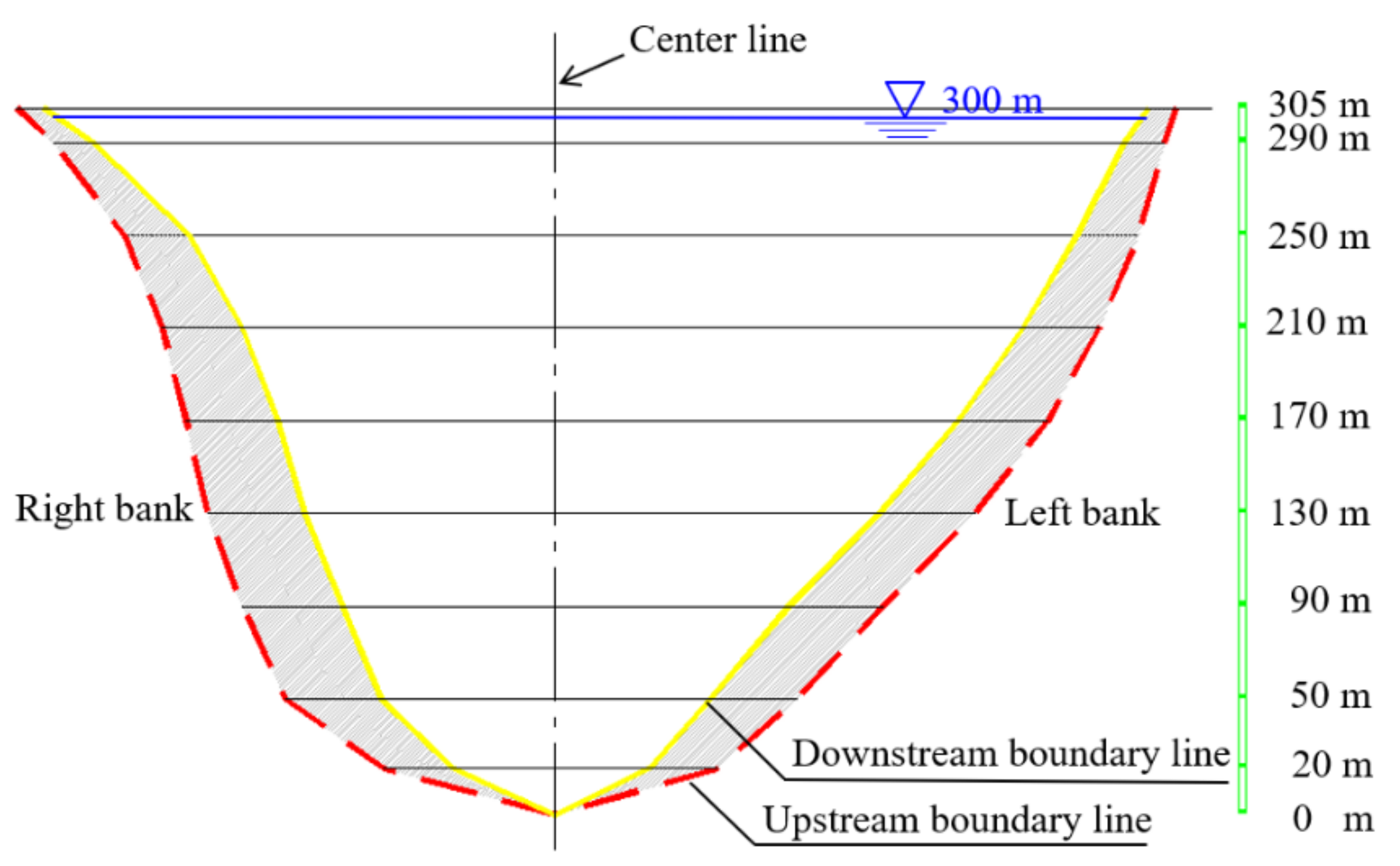
The geometry of the arch dam is given in Figure 1. The arch dam used for analysis in this paper is 305 m high; the width of the dam crest is 13 m, and the width of the dam bottom is 58 m. The average water level was at 300 m. The arch dam with orifices had four upper orifices, each 5 m wide and 10 m high, and five middle orifices, each 5 m wide and 6 m high. It should be noted that some research on the damage characteristics of an arch dam subjected to an underwater contact explosion was carried out in the early stages [21], and this paper is built on the basis of previous research. In the previous simulation model, the transmission boundary condition, which controls the effect of the artificial boundary on shock wave reflection, was applied to the cutoff surface of the rock foundation and the reservoir water. A fixed boundary constraint was applied to the rock bottom.
2.1. Evaluation Index of Local Damage State for Middle Part of the Dam
When the body of an arch dam was affected by an underwater contact explosion, the degree of damage can be qualitatively classified as follows:
- Basically intact. Only the upstream surface of the dam at the point of explosion or the adjacent base surface of the arch dam is damaged. The damaged area is small, and the depth is reasonably close to the surface; the explosion has almost no impact on the regular operation of the dam.
- Minor damage. There is a distinct area of damage to the upstream surface of the dam at the point of explosion or on the adjacent base surface. The damage extends into the interior of the dam body. The dam will fail locally, but the explosion does not cause complete failure of the dam.
- Moderate damage. The upstream and downstream surfaces of the dam at the point of explosion are damaged; damage to the upstream surface extends into the middle of the dam body, or the base surface suffers penetration damage. The dam body around the point of the explosion becomes completely ineffective, and the dam is at increased risk of local penetration damage as the weight of the explosive charge increases.
- Serious damage. The damage to the upstream surface connects with damage to the downstream surface at the point of explosion, or there is a large area of penetration damage at the adjacent base surface. The dam body is partially damaged on both the upstream and downstream faces, reservoir water is discharged, dam performance is lost, and there is a risk of total dam failure.
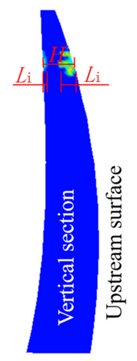
The degree of local damage D is the ratio of the length, i.e., depth of penetration, of damage to the dam at the upstream point of the explosion to the total thickness of the dam body at that point [10]. D is calculated by:
where D is the degree of local damage at the middle of the arch dam and , is the total length of damage along the thickness direction of the dam body, and H is the total thickness of the arch dam at the point of explosion (Figure 2). It should be noted that the damage scale of the dam is from 0 (no damage) to 1 (completely destroyed), in which blue represents no damage and red represents completely destroyed. D is categorized as follows: for , there is minor local damage and the body is essentially intact; for , local damage to the middle part of the dam is minor; for , local damage to the middle part of the dam is moderate; and for , local damage to the middle part of the dam is severe.
2.2. Evaluation Index of Local Damage at the Surface Discharge Holes
Reservoir capacity above the high elevation surface holes for flood discharge is limited. The destruction of a single pier will have a limited impact on the dam or the downstream area. The overall safety of the dam will be affected only when all the piers of the surface discharge holes are destroyed and the discharge holes become connected (Figure 3).
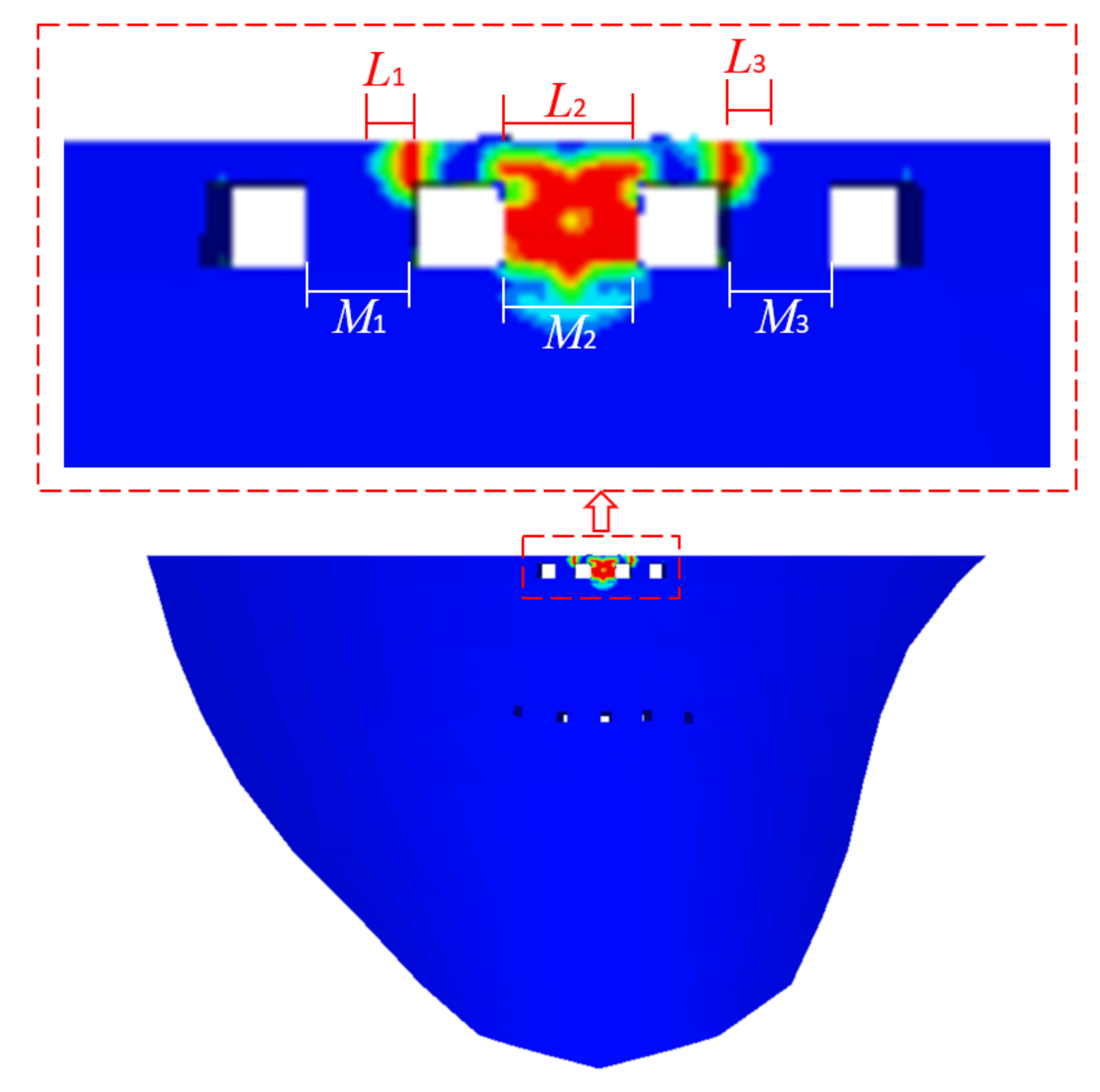
The degree of damage D1 to surface discharge holes after an underwater contact explosion is calculated by:
where D1 is local damage to the surface discharge holes and ; is the width of the damage to the first pier, is the width of the first pier, and N is the total number of piers in the discharge holes, as shown in Figure 3. D1 is categorized as follows: for , the damage is minimal, and the piers are intact; for , the damage is minor; for , the damage is moderate; for , the damage is severe.
2.3. Evaluation Index of Local Damage State for the Deep Discharge Holes
The deep discharge holes are located at the center of the arch dam; the holes are large, and the dam body is thick. When an explosive detonates at the inlet of a hole, the water in the hole is a suitable carrier of the explosion shock wave. This load can seriously damage the inlet and outlet of the hole. As the weight of the charge increases, if damage penetrates the upstream or downstream hole, the overall safety of the dam is threatened.
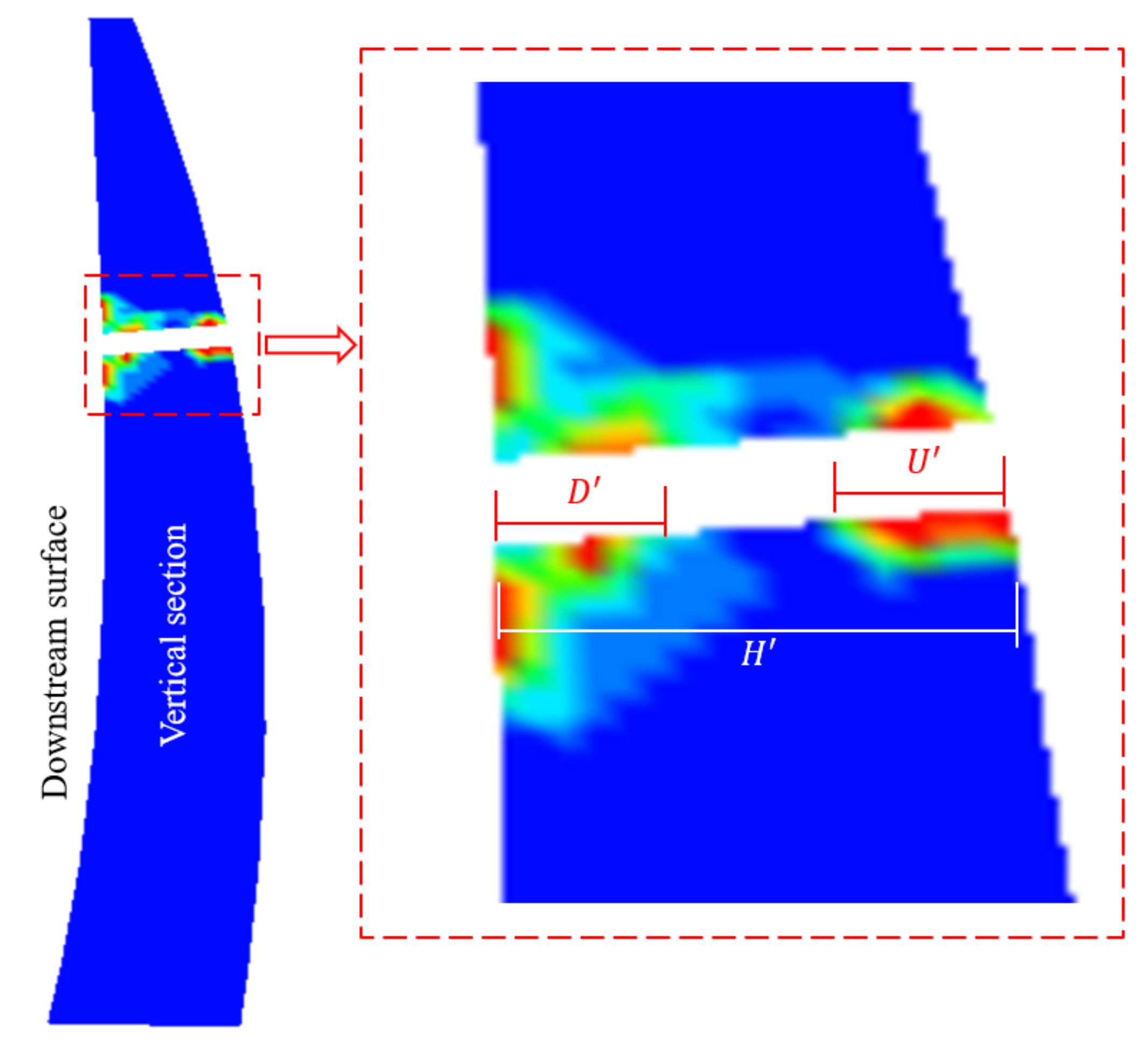
Damage to deep holes from an underwater explosion load at the inlet is considered to be damaged due to penetration of the plastic zone, and the degree of damage D2 is calculated by:
where D2 is local damage to the deep flood discharge holes, and ; is the width of upstream damage to the hole, is the width of downstream damage to the hole, and is the width of the hole (Figure 4). D2 is categorized as follows: for , there is minor damage, and the hole is essentially intact; for , the damage is minor; for , the damage is moderate; and for , the damage is severe.
2.4. Evaluation Index of Local Damage State for the Abutment
When the underwater contact explosion load acts on the abutment of an arch dam, it induces damage to the dam body facing the point of explosion and punching crack damage to the adjacent base surface [21]. The index of local damage to an abutment subjected to an underwater contact explosion load is given by:
where D3 is the degree of local damage to the abutment, is the area of damage to the base surface, H3 is the height of the damage area on the base surface, and is the average extent of the damage zone on the base surface (Figure 5). D3 is categorized as follows: for , there is minor damage, and the abutment is essentially intact; for , the damage is minor, for , the damage is moderate, and for , the damage is severe.
3. Assessment of Damage to an Arch Dam Due to an Underwater Contact Explosion
The underwater contact explosion load is very destructive at the point of contact. We first quantified and assessed the degree of damage to the dam in order to provide a baseline for an improved anti-impact protection design of an arch dam.
3.1. Damage Assessment Model for Middle Part of the Dam
As the mass of the explosive increases from 50 kg to 3000 kg, the damage area on the upstream surface continues to penetrate the dam in the downstream direction, and so the depth of damage continues to increase, as seen in Figure 6. When the mass reaches 2000 kg, the damage originating at the point of impact penetrates from the upstream and downstream surfaces.
Figure 6 shows that when the mass of the explosive is small (50–350 kg), the depth of damage from the upstream surface is <3.5 m. As the mass of the explosive increases, the depth of the damage originating on the upstream surface increases linearly. When the mass of the explosive is 850 kg, 1050 kg, or 1200 kg, the corresponding damage depths are 11.9 m, 13.4 m, and 14.9 m, respectively. The depth of 14.9 m is about half of the total thickness of the arch dam at the point of impact (the center of the detonation). When the mass of the explosive increased from 2000 kg to 3000 kg, the damage depth remained unchanged at 30 m. This is because when the mass of the explosive increased to 2000 kg, the damage from the upstream surface has coalesced with damage from the downstream surface, forming penetration damage.
Equation (1) was used to calculate the degree of damage, and the results are shown in Table 1.
It can be seen from Table 1 that when the mass of explosive was 50–550 kg, the maximum total thickness of damage along the direction of water flow was 5.34 m, and the maximum degree of damage D was 0.18, less than 0.2. Damage to the arch dam was, therefore, slight, and the arch was intact. When the mass of the explosive increased to 850 kg, damage thickness increased to 11.9 m, and the degree of damage D was 0.40, which is in the range 0.2–0.5, indicating minor damage to the middle part of the dam. When the mass of the explosive increased to 1050 kg or 1200 kg, damage thickness increased to 16.36 m and 19.95 m, and the degree of damage was 0.55 and 0.67, both of which are in the range of 0.5–0.8. This result indicates moderate damage to the middle part of the dam. When the mass of the explosive increased to 2000 kg, the damage zone included the upstream and downstream surfaces, and so the thickness of the damage zone was the thickness of the arch, 30 m. Thus, when the mass of the explosive was ≥2000 kg, D reached the upper limit of 1.0.
Using the values of D in a nonlinear regression analysis (Figure 7) produced the following damage assessment model for the middle part of the arch dam subjected to an underwater contact explosion:
where: Q is the mass of explosive (kg), and a, b, and c are constants with values 0.03, 9.41, and 3.74, respectively.
Equation (5) shows that when the explosive charge is 0–560 kg, the middle part of the arch dam is intact. When the mass of the explosive is 560–1010 kg, the middle part of the arch dam suffers minor damage. When the mass of the explosive is 1010–1320 kg, the middle part of the arch dam suffers moderate damage. When the mass of the explosive is >1320 kg, the middle part of the arch dam is seriously damaged.
3.2. Damage Assessment Model for the Surface Flood Discharge Holes
The arch body contains several surface discharge holes, which affect the response of the upper part of the arch dam to a contact explosion. We set the location of the contact explosive to the central pier of the holes and developed a local damage assessment model for the surface flood discharge holes to investigate the behavior of the arch dam in response to a contact explosion.
The lower part of an arch dam is typically thicker and stronger at the base than at the upper part. Thus, penetration damage from a contact explosion is more likely to occur if the piers of the surface discharge holes are the site of the explosion. The use of the ratio of damage thickness to the total dam thickness as an indicator of the extent of the damage in the center of the arch dam, which was the case in Section 3.1, is not applicable for an assessment of local damage at the surface flood discharge holes. This is because the high elevation of the surface flood discharge holes results in there being little reservoir capacity above the bottoms of the holes. Additional flood discharge caused by the collapse of a single pier, such as the middle pier, is equivalent to the flood discharge caused by gate opening in flood season, and the impact on the normal operation of the arch dam and effects on the downstream area are limited. Only when the adjacent piers collapse and more than two discharge holes become connected will serious local damage be caused to the arch dam.
This analysis led us to use Equation (2) to quantify the damage resulting from a contact explosion located at the central pier.
Table 2 gives the calculated values of the degree of damage for different masses of explosives. The table shows that for a 50 kg mass of explosive, the degree of damage D1 was 0.14. This value is in the range 0–0.25, and the discharge holes were essentially intact. When the mass of the explosive was increased to 100 kg, D1 was 0.33. This value is in the range 0.25–0.40, so the damage was minor. When the mass of the explosive was 200 kg or 350 kg, D1 was 0.43 and 0.53, indicating moderate damage. When the mass of the explosive was 550 kg, D1 was 0.79, indicating severe damage to the discharge holes. When the mass of the explosive was 850–1200 kg, all three piers were damaged and overtopped. D1, in this case, was 1.0, and serious damage had occurred at the discharge holes.
We fitted an Equation to enable a rapid calculation of the degree of damage and provide a baseline reference for designing impact explosion-resistant surface flood discharge holes in an arch dam based on the mass of the explosive. The fitting, which was based on a large number of calculations, is shown in Figure 8, which gives the value of D1 for various masses of explosives. The Equation for the degree of damage D1 obtained by fitting is:
where Q is the mass of explosive, in the range 0–816 kg, and a1 and b1 are constants with values 0.001 and 0.184.
The category of damage to the discharge holes corresponding to the mass of the explosive can be derived from the calculation of Equation (6), as shown in Figure 9. The categories are as follows:
- Basically intact. The mass of the explosive is in the range 0–66 kg. There is little impact on the holes from the explosion, so the discharge holes are essentially intact.
- Minor damage. The mass of the explosive is in the range 66–216 kg. The explosion causes damage only to the pier in contact with the explosive, so the damage is minor.
- Moderate damage. The mass of the explosive is in the range 216–566 kg. The explosion destroys the pier in contact with the explosive and causes crack damage at the top and bottom of the adjacent piers; the damage is moderate.
- Serious damage. The mass of the explosive is >566 kg. The explosion completely destroys the pier in contact with the explosive and causes penetration crack damage to the adjacent pier. All the piers are damaged, so the damage is serious.
3.3. Damage Assessment Model for the Deep Flood Discharge Holes
In addition to the surface flood discharge holes, deep flood discharge holes are usually set in the middle of an arch dam body for flood control. These holes have a lower elevation and a greater thickness than the surface holes due to the design of the arch. However, these holes reduce the stiffness and strength of the surrounding dam body, which can affect the arch response to a contact explosion. We modeled an underwater contact explosion when the point of contact and the explosive load were at the inlet of the central deep flood discharge hole to investigate the effect on the arch structure.
Although, in contrast to the surface holes, the deep flood discharge hole spacing is larger, and the dam body is thicker, in case there is a contact explosion at the hole location, the water in the hole will carry the shock wave, resulting in severe damage to the inlet and outlet of the hole. As the mass of the explosive increases and damage becomes contiguous from inlet to outlet, the hole will not function normally, and the unanticipated discharge of reservoir water will prevent normal operation of the dam and threaten its safety.
This analysis determined that the inlet and outlet of the deep flood discharge holes should form the basis of the damage indicator D2 and developed Equation (3) to calculate the degree of damage.
Table 3 gives the total damage length along the length of the hole, as used in Equation (3), and the extent of local damage D2 calculated using the Equation. The table shows that when the mass of the explosive was 50 kg or 100 kg, there was minor damage, with values of D2 0.01 and 0.10. The discharge holes were basically intact. When the mass of the explosive was 200 kg, D2 was 0.32, and damage was minor. When the mass of the explosive was 350 kg or 550 kg, D2 was 0.66 and 0.77, and the damage was moderate. When the mass of the explosive was 850 kg, D2 was 0.90, which is greater than 0.85, and the damage was severe. When the mass of the explosive was 1050 kg or 1200 kg, all the discharge holes were damaged, and D2 reached the maximum value 1.00; the damage was serious.
The preceding analysis shows that D2 is directly related to the mass of the explosive. We fitted an equation to enable rapid calculation of the degree of damage and provide a baseline reference for designing impact explosion-resistant deep flood discharge holes in an arch dam based on the mass of the explosive. The fitting was based on several calculations, as shown in Figure 10, which gives the value of D2 for various masses of explosive. The Equation for the degree of damage D2 obtained by fitting is:
where Q is the mass of explosive, and a2, b2, and c2 are constants with values −1.2, 358 and 1.0.
The degree of damage category can be obtained from the value of D2 calculated by Equation (7) using the classification shown in Figure 11.
The damage categories are described as follows:
- Basically intact. The mass of the explosive is 0–190 kg; the explosion causes only cracking and damage at the corners of the inlet holes, and there is no explosion damage in other areas.
- Minor damage. The mass of the explosive is 190–400 kg. The explosion causes only local damage at the inlet and outlet of the hole at the center of the explosion.
- Moderate damage. The mass of the explosive is 400–750 kg. The explosion causes penetration damage to the hole at the center of the explosion and cracking damage to the base of the middle piers at the outlet; cracks develop into the adjacent holes.
- Serious damage. The mass of the explosive is >750 kg. The explosion causes penetration damage to the hole at the center of the explosion and penetration cracking to the base and apex of the middle piers; the three holes become connected.
3.4. Damage Assessment Model for the Abutment
The main failure modes of the arch dam when the upstream surface of the abutment is subjected to an underwater contact explosion load are compression failure in the contact zone, tensile failure of the downstream surface, and shear damage to the adjacent base surface. The damage area of the dam at the point of explosion and on the downstream surface is small, and it is located inside the dam and does not affect the overall stability of the arch. However, as the quantity of the explosive increases, the damage area on the base surface rapidly expands. We used the ratio of the damage area to base surface area as the primary index D3 of local damage to the dam abutment. The calculation of the ratio is shown in Equation (4).
Table 4 shows the calculated value of D3 for different masses of explosive. When the mass of the explosive was 50 kg, there was no damage to the base surface. The value of D3 was 0, which is in the range 0–0.20, so the abutment was basically intact. When the weight of the explosive was increased to 100 kg, the value of D3 was 0.22, which is in the range 0.20–0.40 and represents minor damage to the abutment. When the mass of the explosive was increased to 200 kg or 350 kg, the values of D3 were 0.45 and 0.60, which represent moderate damage to the abutment. When the mass of the explosive reached 550 kg, D3 was 0.66, representing serious damage to the abutment. When the mass of the explosive was 1200 kg, the damage and failure area of the base surface extended almost to the dam crest; D3 was 0.77, and damage to the abutment was severe.
We fitted an equation to enable rapid calculation of the degree of damage to the abutment and to provide a baseline reference for designing an impact explosion-resistant arch dam based on the mass of the explosive. The fitting was based on a number of calculations, as shown in Figure 12, and gives the value of D3 for various masses of explosive. The Equation for the degree of damage D3 obtained by fitting is:
where Q is the mass of the explosive, and a3, t3, and b3 are constants with values −0.96, 172 and 0.74, respectively.
The mass of the explosive corresponding to the state of local damage to the abutment can be calculated from Equation (8), as shown in Figure 13.
- Basically intact. The mass of the explosive is in the range 0–96 kg, and the abutment is basically intact; force is transferred normally between the dam body and the abutment bedrock.
- Minor damage. The mass of the explosive is in the range 96–185 kg, and the impact explosion causes damage only to the base surface at the same elevation as the point of explosion; damage to the abutment is minor.
- Moderate damage. The mass of the explosive is in the range 185–350 kg, and the explosion load causes complete damage to the surface of the base at the same elevation as the point of explosion; the damage extends along the surface of the base upward and downward, and damage to the abutment is moderate.
- Serious damage. The mass of the explosive is >350 kg; the explosion load completely destroys the adjacent base surface, and damage to the base surface extends upward almost to the dam crest; there is severe damage to the abutment.
4. Safety Assessment Model for the Overall Stability of an Arch Dam Subjected to Underwater Contact Explosion
In theory, local failure of the arch body does not result in the complete failure of the dam. The complete failure of an arch dam is due to the continuous accumulation of localized damage that ultimately destroys the stability of the dam [22]. The ultimate bearing capacity of an arch dam is often used as an indicator of the overall stability of the dam. It is generally understood that a large deformation will completely damage the arch structure and that the dam will not continue to bear the load after a large deformation.
4.1. Safety Assessment of the Stability of an Arch Dam with Damage at the Center of the Arch
When a small underwater contact explosion load acts on the central part of an arch dam, the dam suffers mainly local damage, and the dam body at a distance from the point of the explosion remains intact. As the mass of the explosive increases, the underwater contact explosion induces local penetration damage to the arch, but this does not affect the overall stability and safety of the dam. When the mass of the explosive reaches a particular value, the area of local penetration damage dramatically expands, and there is the possibility of structural damage to the entire arch. If the entire structure is damaged, the stability of the entire dam is affected.
We propose the following model, based on the degree of damage to the central part of the arch, to assess the overall stability of an arch dam:
where is the area of damage in the vertical section of the arch, is the total vertical cross-sectional area of the arch above the lowest point of damage in the vertical section, as shown in Figure 14, and is the degree of damage to the entire arch. (0.75 is the critical value) represents a total failure of the arch dam.
Calculation of the critical value of , the point at which dam failure occurs, is as follows: When local damage occurs in the vertical section (Figure 14), the shared load is transferred to the dam body above the damage zone. As the damage area increases, the stress of the dam body above the damage zone gradually increases until it reaches the compressive strength of the material of which the arch is constructed.
An arch dam is designed so that dam body stress is determined by the partial factor limit state [23]:
where is the structure importance coefficient and the value is 1.0, is the design condition coefficient and the value is 1.0, is the main stress, is the structural coefficient, and the value is 2.0, is concrete strength, and is the partial coefficient of material performance and the value is 2.0. Substituting the parameter values into Equation (10), the result is , and the safest value is . When the local damage area of the vertical section is >75% of the total area of the arch cross-section above the lowest part of the damage, the concrete will reach its compressive strength. Therefore, when in Equation (9), the entire arch dam will be in a failure state.
4.2. Safety Assessment of Overall Stability of Arch Dam with Damage on Abutment
The antisliding stability of the arch dam along the base surface is analyzed as a rigid body in limited equilibrium. It is assumed that there are neither cohesive nor frictional forces on the damaged surface of the base. It is difficult to obtain an overall antisliding stability safety factor for the arch dam because the base surface is complex. Therefore, we first analyze the antisliding stability safety factor for each arch contour band and then further analyze the overall antisliding stability of the arch dam.
Shear damage to the base surface resulting from an underwater contact explosion is located in the upper part of the arch dam; the lower part of the dam is unaffected by the explosion. We, therefore, analyzed only the stability of each arch contour above a height of 165 m (Figure 15).
The antisliding stability safety factor of contour i at the base surface is given by Equation (11). Parameter values and coefficients in the Equation are taken from the arch dam design code [23]:
where is the structure importance coefficient with the value of 1.1, is the design condition coefficient with the value of 1.0, and are the friction coefficient and the cohesion coefficient of the base surface, and their values are 1.18 and 1.643 (MPa) [24], is the structural coefficient with the value of 1.2, and are partial coefficients of material properties, and their values are 2.4 and 3.0, is the area of damage on the base surface at contour I, is the total area of the base surface at contour I, and and (GN) are the normal force and the sliding force on the base surface at contour i.
The justification for transferring the analysis of antisliding stability from a single contour to the entire arch is as follows: When the antisliding stability safety factor of a contour is <1.0, the excess sliding force on the contour is distributed to the adjacent superior contour, that is, the sliding force of the contour is readjusted. For example, if the antisliding stability of contour i cannot meet the safety requirements, the sliding force of contours i and i+1 are adjusted using Equations (12) and (13):
where and are the sliding force on the base surface at contours i and i + 1 after adjustment. Contour i + 1 is immediately above contour i.
After adjusting the sliding force using Equations (12) and (13), , we check the antisliding stability safety factor for contour i + 1. We decide whether to continue to allocate sliding force to the superior contour (i + 2) according to Equation (14):
If the process terminates before reaching the uppermost contour, we consider the entire dam to be stable. If is <1.0 when the uppermost contour is reached, we consider the entire dam unstable along the base surface.
In Equations (12) and (14), excess sliding force is transferred upward to the adjacent contour, and the downward transfer was not considered. This is because when an underwater contact explosion occurs, a horizontal crack appears at the bottom of the damaged area of the base surface, which seriously weakens the interaction between the body of the arch above and below the crack.
5. Assessment of Overall Stability of an Arch Dam Damaged by Local Contact Explosion
In this section, we analyze the overall stability of an arch dam that has local damage due to a contact explosion in the central part of the arch dam and damage to the abutment.
5.1. Assessment of Overall Stability of an Arch Dam with Damage to the Middle Part of the Dam
When the underwater contact explosion load acts on the middle part of the arch, it induces damage mainly in the zone surrounding the point of explosion, and the damage area expands as the mass of explosive increases. Under the static load of reservoir water, when the stress of the undamaged body of the arch exceeds the compressive strength of the construction material, the arch structure will fail.
Table 5 shows, for the vertical section of the arch dam, area Szf (the total area of damage above the lowest point of damage), area Sz (the total area of the arch above the lowest point of damage) (Figure 14), and Kc (which indicates the degree of damage to the entire arch as calculated by Equation (9)), for each quantity of explosive. It can be seen from the table that when the mass of the explosive is <1200 kg, the explosion load induces only local damage to the arch dam, and the area of damage on the vertical section is small. In this case, Kc < 0.20, and so the safety of the entire dam is unaffected. Kc is 0.21 when the mass of the explosive is 1200 kg, which is considerably less than the critical threshold value of 0.75. When the mass of the explosive increases to 2000 kg, the damage area on the vertical section is 918 m2 and Kc is 0.61, which is still less than 0.75, and therefore the dam is still stable. However, when the mass of the explosive increases to 3000 kg, the damage area is 1249 m2, which is about 76% of the total area of the vertical section above the lowest point of damage. In this case, Kc > 0.75; the arch structure above the explosion is damaged, and the stability of the entire arch dam was in a state of failure.
The failure of the arch structure in the middle part of the arch dam is directly related to the damage area on the vertical section, which is determined by the mass of the explosive. The model for the degree of damage to the arch structure Kc, which was obtained by linear fitting (Figure 16), is:
where Q is the mass of explosive and and are constants with values 3.09 × 10⁻⁴ and −0.12, respectively.
Using Equation (15), we find that the critical mass of the explosive that causes instability failure of the entire dam is 2800 kg (Figure 16). Figure 16 shows that when the mass of the explosive is <2800 kg and Kc < 0.75, the arch structure is not damaged by the contact explosion and remains stable. However, when the mass of the explosive exceeds 2800 kg and Kc > 0.75, the stress of the entire dam body is greater than the material strength of the construction material due to the large area of damage in the central part of the arch, resulting in the damage failure of the arch structure and instability of the entire dam.
The preceding analysis shows that a contact explosion with the mass of explosive >2800 kg will destroy the overall stability of the arch dam. Explosion damage from a lesser quantity of explosive will remain localized in the central part of the arch and will not affect the stability of the entire dam.
5.2. Assessment of Overall Dam Stability with Damage to the Abutment
The stresses acting on each arch contour during normal dam operation are shown in Figure 17: F is the hydraulic thrust on the upstream arch surface for normal water level, N is the positive pressure, and T is the sliding force on the base surface. The values of N and T are calculated using the finite element analysis and are shown in Table 6. The basic loads in the finite element model are reservoir water pressure and dam gravity.
5.2.1. Antisliding Stability at the Base Surface for Each Arch Contour
Table 7 shows the antisliding stability safety factor at the base surface calculated by Equation (11) for each arch contour. It can be seen from Table 7 that the underwater contact explosion load at the abutment has a significant effect on the antisliding stability of each contour. As the mass of the explosive increases, the antisliding stability safety factor of a contour with a damaged base surface decreases rapidly, and some contours display sliding instability.
Table 7 shows that when there was no explosive, the antisliding stability safety factor of each contour was >1.0, showing that there was antisliding stability at the point of contact between the base and the arch for all contours. When the mass of the explosive was 50 kg, the base surface was not damaged, and there was antisliding stability at the point of contact between the base and the arch for all contours. When the mass of the explosive was 100 kg, although the safety factors of the three contours with heights of 225–235 m, 235–245 m, and 245–255 m were reduced to 1.51, 1.57, and 1.78, respectively, the values were all >1; thus, there was an antisliding stability at the point of contact between the base and the arch for all contours.
When the mass of the explosive was 200 kg, eight contours showed reduced antisliding stability, and the safety factor of three contours was 0.61, which is <1.0, indicating that at the point of contact between the contour and the base, there was a loss of sliding stability. When the mass of the explosive was 350 kg, nine contours showed reduced antisliding stability, and four contours had values 0.52, 0, 0.23, and 0.80, all of which are <1.0. The reason the contour with the height of 205–215 m had an antisliding stability safety factor 0 is that the base surface at the point of contact was damaged due to the explosion load. When the mass of the explosive was 550 kg, 11 contours showed reduced antisliding stability, five of which were <1.0 and three of which (195–205 m, 205–215 m, and 225–235 m) were 0. When the mass of the explosive was 1200 kg, the antisliding stability safety factor of every contour was reduced. In this case, the antisliding stability safety factor of eight contours was <1.0, and three contours (195–205 m, 205–215 m, and 225–235 m) had values of 0.
The preceding analysis shows that when the mass of the explosive was ≥200 kg, the antisliding stability safety factor of some contours was <1.0 and that at the points of contact with the base, there was sliding instability. However, this does not necessarily translate into the instability of the entire dam because the arch dam itself is a static indeterminate structure that can reach a new stable state through the readjustment of forces and loads in response to local damage. Thus, the interactions of different contours must be considered in the analysis of the stability of the entire arch dam.
5.2.2. Analysis of Antisliding Stability along the Base Surface for the Entire Dam
When the antisliding stability safety factor of a contour was <1.0, stability analysis of the entire dam was conducted using Equations (12)–(14), and the results are shown in Table 8.
Table 8 shows that when the mass of the explosive was 200 kg, the antisliding stability safety factor for three contours (195–205 m, 205–215 m, and 215–225 m) was <1.0. However, for the 255–265 m contour, Equations (12) and (13) produced an antisliding stability safety factor 1.19, which indicates sliding stability for this contour, and therefore stability for the entire dam. When the mass of the explosive was 350 kg, 550 kg, or 1200 kg, after adjusting the superior contours using Equations (12) and (13), the antisliding stability safety factors of the uppermost contours were respectively 0.27, 0.07, and 0.05, all of which are <1.0. Thus, in these cases, the entire dam lost its antisliding stability, potentially making the arch slide along the base surface.
Table 8 shows that when the mass of the explosive was 200 kg, the entire arch dam remained stable, but when the mass of the explosive increased to 350 kg, 550 kg, or 1200 kg, the entire dam lost its antisliding stability.
The antisliding stability of the arch dam at the base surface is directly related to the damage area at the base surface, which is determined by the mass of the explosive. The Equation to predict the antisliding stability safety factor K0 was obtained by linear fitting:
where Q is the mass of explosive, and , , and are constants with values 1.2, 340 and 0.51, respectively.
The critical value of the mass of the explosive, 310 kg, at which the entire dam loses antislide stability, can be calculated from Equation (16), as shown in Figure 18. When the mass of the explosive acting on the abutment is <310 kg, K0 > 1, the arch dam displays antisliding stability. When the mass of explosive >310 kg, K0 < 1.0, the arch dam loses stability along the base surface.
The preceding analysis shows that when the abutment is affected by the underwater contact explosion, the quantity of 310 kg explosive can destroy the antisliding stability of the entire arch dam. Therefore, in a contact explosion-resistant design, more attention should be paid to the abutment of the arch dam and particularly to damage to the base surface.
6. Conclusions
We created the evaluation indexes and prediction models of local damage at different locations on the dam. The possibility of a local contact explosion causing structural failure of the arch or sliding instability of the dam at the base surface was demonstrated. On this basis, a stability assessment method for the entire arch dam that suffered the explosion damages was developed. Finally, the overall stability and safety of the arch dam subjected to underwater contact explosion were analyzed and assessed.
This study developed the evaluation indexes and prediction models of local damage at different locations on the dam. A local contact explosion likely causes structural failure of the arch or sliding instability of the dam at the base surface. This study also proposed a method for assessing the stability of the entire arch dam after explosion damages were developed. Thus, the overall stability and safety of the arch dam subjected to underwater contact explosion were analyzed and assessed.
- We created local damage assessment models and damage prediction models using the penetration depth of explosion damage in the center of the arch dam into the dam body, the continuous cracking length of the piers in the surface flood discharge holes, the degree of penetration damage at the deep flood discharge holes, and the sheer damage area of the base surface as damage variables.
- We developed a method to assess local explosion damage for analyzing local damage at different parts of an arch dam. We found that when the underwater contact explosion action parts consist of the center of the arch, the surface flood discharge holes, deep flood discharge holes, and the abutment, the quantities of the explosive required to cause serious local damage are 1320 kg, 566 kg, 750 kg, and 350 kg, respectively.
- The underwater contact explosion affects the central part of the dam and the abutment. It threatens the overall stability of the dam by destroying the arch structure and the base surface. Our examination of the spatial distribution of explosion damage led us to develop equations to predict the impact of explosion damage on the overall stability of the arch dam and to create a prediction model of the overall instability of the arch dam.
- Explosion damage at the abutment had a more significant impact on the overall stability of the arch dam than the damage at the central part of the arch. When the contact explosion action location is on the abutment, it only needs 310 kg to cause the overall damage of the arch dam, while when the action location is on the middle part of the dam, the quantity of the explosive required is 2800 kg. Therefore, in the safety assessment of an arch dam damaged by a contact explosion, most attention should be given to damage on the abutment.
In the design and later operation of the high arch dam, attention should be paid to the protect dam abutment from explosion damage. Some engineering measures may include increasing the concrete strength, reinforcing dam abutment on the arch end face, improving the safety protection level of dam abutment, and expanding the prohibited range in daily operation.
Author Contributions
Conceptualization, X.Z.; Data curation, H.F.; Funding acquisition, Y.F.; Investigation, G.W.; Software, Y.F. All authors have read and agreed to the published version of the manuscript.
Funding
This research was funded by National Natural Science Foundation of China, grant number 52009126, by Key scientific research projects of colleges and universities in Henan Province, grant number 21A570006, and by the Outstanding Young Talent Research Fund of Zhengzhou University, grant number 1621323001.
Institutional Review Board Statement
Not applicable.
Informed Consent Statement
Not applicable.
Data Availability Statement
Not applicable.
Acknowledgments
The authors gratefully appreciate the supports from the National Natural Science Foundation of China (52009126), Key scientific research projects of colleges and universities in Henan Province (21A570006), the Outstanding Young Talent Research Fund of Zhengzhou University (1621323001).
Conflicts of Interest
The authors declare no conflict of interest.
References
- USACE. Earthquake Design and Evaluation of Concrete Hydraulic Structures; USACE: Washington, DC, USA, 2007. [Google Scholar]
- Shen, H.Z.; Zhang, C.H.; Kou, L.H. Performance-based seismic damage assessment model for concrete gravity dams. J. Tsinghua Univ. Sci. Technol. 2007, 47, 2114–2118. [Google Scholar]
- Heshmati, M.; Hariri-Ardebili, M.; Seyed, K. Are There Any Differences in Seismic Performance Evaluation Criteria for Concrete Arch Dams? Civ. Eng. Infrastruct. 2013, 46, 233–240. [Google Scholar]
- Hariri-Ardebili, M.A.; Sudret, B. Polynomial chaos expansion for uncertainty quantification of dam engineering problems. Eng. Struct. 2020, 203, 109631. [Google Scholar] [CrossRef]
- Hariri-Ardebili, M.A.; Mahdavi, G.; Abdollahi, A.; Amini, A. An RF-PCE Hybrid Surrogate Model for Sensitivity Analysis of Dams. Water 2021, 13, 302. [Google Scholar] [CrossRef]
- Hariri-Ardebili, M.A.; Heshmati, M.; Boodagh, P.; Salamon, J.W. Probabilistic Identification of Seismic Response Mechanism in a Class of Similar Arch Dams. Infrastructures 2019, 4, 44. [Google Scholar] [CrossRef] [Green Version]
- Hariri-Ardebili, M.; Saouma, V.; Porter, K. Quantification of seismic potential failure modes in concrete dams. Earthq. Eng. Struct. D 2016, 45, 979–997. [Google Scholar] [CrossRef]
- Alembagheri, M. Earthquake damage estimation of concrete gravity dams using linear analysis and empirical failure criteria. Soil. Dynam. Earthq. Eng. 2016, 90, 327–339. [Google Scholar] [CrossRef]
- Alembagheri, M. A study on structural safety of concrete arch dams during construction and operation phases. Geotech. Geol. Eng. 2019, 37, 571–591. [Google Scholar] [CrossRef]
- Wang, X.H.; Zhang, S.R.; Wang, C.; Cui, W.; Cao, K.L.; Fang, X. Blast-induced damage and evaluation method of concrete gravity dam subjected to near-field underwater explosion. Eng. Struct. 2020, 209, 109996. [Google Scholar] [CrossRef]
- Li, J.; Chen, J.Y.; Xu, Q. Study on index of seismic performance evaluation of arch dam. J. Hydraul. Eng. 2015, 46, 118–124. [Google Scholar]
- Zhang, Q.L.; Li, D.Y.; Wang, F.; Li, B. Numerical simulation of nonlinear structural responses of an arch dam to an underwater explosion. Eng. Fail. Anal. 2018, 91, 72–91. [Google Scholar] [CrossRef]
- Zhang, Q.L.; Li, D.Y.; Hu, C.; Hu, L. Numerical Investigation into Underwater Explosion–Resistant Performance of an Arch Dam Considering Its Transverse Contraction and Control Joints. Perform. Constr. Facil. 2019, 33, 4019078. [Google Scholar] [CrossRef]
- Moradloo, A.J.; Adib, A.; Pirooznia, A. Damage analysis of arch concrete dams subjected to underwater explosion. Appl. Math. Model. 2019, 75, 709–734. [Google Scholar] [CrossRef]
- Moradi, M.; Aghajanzadeh, S.; Mirzabozorg, H. Underwater explosion and its effects on nonlinear behavior of an arch dam. Coupl. Syst. Mech. 2018, 7, 333–351. [Google Scholar]
- Zhu, F.; Zhu, W.; Fei, D. Modelling and analysis of arch dam withstand underwater explosion. Int. J. Comput. Appl. T. 2013, 48, 272–280. [Google Scholar] [CrossRef]
- Zhu, F.; Zhu, W.H.; Zhu, X.X.; Sun, J.B.; Hua, X. Numerical simulation of arch dam withstand underwater explosion. In Proceedings of the 2012 International Conference on Modelling, Identification and Control (ICMIC), Wuhan, China, 24–26 June 2012; pp. 1034–1039. [Google Scholar]
- Kalateh, F. Dynamic failure analysis of concrete dams under air blast using coupled Euler-Lagrange finite element method. Front. Struct. Civ. Eng. 2019, 13, 15–37. [Google Scholar] [CrossRef]
- Xue, X.H.; Yang, X.G.; Zhang, W.H. Numerical modeling of arch dam under blast loading. J. Vib. Control 2014, 20, 256–265. [Google Scholar] [CrossRef]
- Ren, Q.W.; Qian, X.D.; Zhao, Y. Methods for analyzing sliding resistance stability along the base surface of high arch dam. J. Hydraul. Eng. 2002, 33, 1–7. [Google Scholar]
- Zhao, X.H.; Wang, G.H.; Lu, W.B.; Zhou, C.B. Safety evaluation method of a high arch dam with abutment suffered contact explosion. J. Vib. Shock. 2020, 39, 265–272. (In Chinese) [Google Scholar]
- Chen, B.; Gu, C.S.; Bao, T.F.; Wu, B.B.; Su, H.Z. Failure analysis method of concrete arch dam based on elastic strain energy criterion. Eng. Fail. Anal. 2016, 60, 363–373. [Google Scholar] [CrossRef]
- DL/T5346-2006. Design Specification for Concrete Arch Dams; China Power Press: Beijing, China, 2006. [Google Scholar]
- Yu, T.T.; Ren, Q.W. Evaluation of Global Safety Degree of Jinping High Arch Dam. Chin. J. Rock. Mech. Eng. 2007, 26, 787–794. [Google Scholar]
Figure 1.
The geometry of the arch dam.

Figure 2.
Parameters of local damage to the middle part of the dam.

Figure 3.
Parameters of local damage for the surface discharge holes.

Figure 4.
Parameters of local damage for the deep flood discharge holes.

Figure 5.
Parameters for local damage to the abutment.

Figure 6.
Damage extension depth of the upstream surface of the arch dam.

Figure 7.
Degree of damage to the middle part of the arch dam for different masses of explosives.

Figure 8.
Degree of the damage to surface flood discharge holes for different masses of explosive.

Figure 9.
The degree of damage to the surface flood discharge holes for different masses of explosive.
Figure 9.
The degree of damage to the surface flood discharge holes for different masses of explosive.

Figure 10.
The degree of damage to the deep flood discharge holes for different masses of explosive.
Figure 10.
The degree of damage to the deep flood discharge holes for different masses of explosive.

Figure 11.
Degree of damage to deep flood discharge holes different masses of explosive.

Figure 12.
The degree of damage to the abutment for different masses of explosive.

Figure 13.
The degree of damage to the abutment for different masses of explosive.

Figure 14.
Schematic showing the parameters of the safety assessment of an arch dam with damage in the central part of the arch.
Figure 14.
Schematic showing the parameters of the safety assessment of an arch dam with damage in the central part of the arch.

Figure 15.
Locations used in antisliding stability analysis.

Figure 16.
The degree of damage Kc to the middle part of the arch dam for different masses of explosive.
Figure 16.
The degree of damage Kc to the middle part of the arch dam for different masses of explosive.

Figure 17.
Force schematic for the analysis of antisliding stability at the base surface.

Figure 18.
The antisliding stability safety factor K0 for the arch dam for different masses of explosive.
Figure 18.
The antisliding stability safety factor K0 for the arch dam for different masses of explosive.


Table 1.
Degree of damage to the arch dam when the middle part of the dam was subjected to underwater contact explosion.
Table 1.
Degree of damage to the arch dam when the middle part of the dam was subjected to underwater contact explosion.
| Mass of TNT (Trinitrotoluene) (kg) | 50 | 100 | 200 | 350 | 550 | 850 | 1050 | 1200 | 2000 | 3000 |
|---|---|---|---|---|---|---|---|---|---|---|
| Damage thickness (m) | 1.25 | 1.49 | 1.90 | 3.05 | 5.34 | 11.90 | 16.36 | 19.95 | 30 | 30 |
| Degree of damage D | 0.04 | 0.05 | 0.06 | 0.10 | 0.18 | 0.40 | 0.55 | 0.67 | 1.00 | 1.00 |
Table 2.
Degree of damage to surface flood discharge holes subjected to underwater contact explosion.
Table 2.
Degree of damage to surface flood discharge holes subjected to underwater contact explosion.
| Mass of TNT (kg) | 50 | 100 | 200 | 350 | 550 | 850 | 1050 | 1200 |
|---|---|---|---|---|---|---|---|---|
| D1 | 0.14 | 0.33 | 0.43 | 0.53 | 0.79 | 1.00 | 1.00 | 1.00 |
Table 3.
Degree of damage to deep flood discharge holes when subjected to underwater contact explosion.
Table 3.
Degree of damage to deep flood discharge holes when subjected to underwater contact explosion.
| Mass of TNT (kg) | 50 | 100 | 200 | 350 | 550 | 850 | 1050 | 1200 |
|---|---|---|---|---|---|---|---|---|
| (m) | 1.27 | 8.78 | 28.64 | 57.14 | 67.36 | 78.52 | 87 | 87 |
| D2 | 0.01 | 0.10 | 0.32 | 0.66 | 0.77 | 0.90 | 1.00 | 1.00 |
Table 4.
The degree of damage to the abutment when subjected to an underwater contact explosion.
| Mass of TNT (kg) | 50 | 100 | 200 | 350 | 550 | 1200 |
|---|---|---|---|---|---|---|
| D3 | 0.00 | 0.22 | 0.45 | 0.60 | 0.66 | 0.77 |
Table 5.
The damage degree of the arch structure of the dam suffered an underwater contact explosion.
Table 5.
The damage degree of the arch structure of the dam suffered an underwater contact explosion.
| Mass of TNT (kg) | 550 | 850 | 1050 | 1200 | 2000 | 3000 |
|---|---|---|---|---|---|---|
| Szf (m2) | 81 | 169 | 239 | 282 | 918 | 1249 |
| Sz (m2) | 1194 | 1297 | 1354 | 1367 | 1494 | 1632 |
| Kc | 0.07 | 0.13 | 0.18 | 0.21 | 0.61 | 0.76 |
Table 6.
The magnitude of positive pressure and sliding force on the base surface for each arch contour.
Table 6.
The magnitude of positive pressure and sliding force on the base surface for each arch contour.
| Contour Height (m) | 295– 305 | 285– 295 | 275– 285 | 265– 275 | 255– 265 | 245– 255 | 235– 245 | 225– 235 | 215– 225 | 205– 215 | 195– 205 | 185– 195 | 175– 185 | 165– 175 |
|---|---|---|---|---|---|---|---|---|---|---|---|---|---|---|
| N (GN) | −0.01 | 0.14 | 0.30 | 0.56 | 1.06 | 0.89 | 1.48 | 1.25 | 1.93 | 1.61 | 1.76 | 2.96 | 1.65 | 2.59 |
| T (GN) | 0.07 | 0.09 | 0.11 | 0.19 | 0.35 | 0.27 | 0.47 | 0.40 | 0.56 | 0.46 | 0.57 | 0.90 | 0.52 | 0.83 |
Table 7.
Effect of underwater contact explosion on antisliding stability safety factor of each contour.
Table 7.
Effect of underwater contact explosion on antisliding stability safety factor of each contour.
| Height (m) | 295– 305 | 285– 295 | 275– 285 | 265– 275 | 255– 265 | 245– 255 | 235– 245 | 225– 235 | 215– 225 | 205– 215 | 195– 205 | 185– 195 | 175– 185 | 165– 175 |
|---|---|---|---|---|---|---|---|---|---|---|---|---|---|---|
| Without explosive | 1.94 | 2.44 | 2.35 | 2.05 | 1.87 | 1.89 | 1.67 | 1.60 | 1.73 | 1.75 | 1.52 | 1.60 | 1.53 | 1.50 |
| 50 kg | 1.94 | 2.44 | 2.35 | 2.05 | 1.87 | 1.89 | 1.67 | 1.60 | 1.73 | 1.75 | 1.52 | 1.60 | 1.53 | 1.50 |
| 100 kg | 1.94 | 2.44 | 2.35 | 2.05 | 1.87 | 1.78 | 1.57 | 1.51 | 1.73 | 1.75 | 1.52 | 1.60 | 1.53 | 1.50 |
| 200 kg | 1.94 | 2.44 | 2.35 | 2.05 | 1.68 | 1.55 | 1.41 | 1.35 | 0.61 | 0.61 | 0.61 | 1.14 | 1.53 | 1.50 |
| 350 kg | 1.94 | 2.44 | 2.35 | 1.85 | 1.49 | 1.42 | 1.31 | 1.12 | 0.52 | 0 | 0.23 | 0.80 | 1.53 | 1.50 |
| 550 kg | 1.94 | 2.44 | 2.23 | 1.85 | 1.49 | 1.33 | 1.00 | 0 | 0.40 | 0 | 0 | 0.64 | 1.23 | 1.50 |
| 1200 kg | 1.55 | 1.95 | 2.00 | 1.54 | 1.21 | 0.95 | 0.67 | 0 | 0.27 | 0 | 0 | 0.40 | 0.77 | 1.20 |
Table 8.
Effects of underwater contact explosion on antisliding stability safety factor of the entire dam.
Table 8.
Effects of underwater contact explosion on antisliding stability safety factor of the entire dam.
| Contour Height (m) | 295– 305 | 285– 295 | 275– 285 | 265– 275 | 255– 265 | 245– 255 | 235– 245 | 225– 235 | 215– 225 | 205– 215 | 195– 205 | 185– 195 | 175– 185 | 165– 175 | |
|---|---|---|---|---|---|---|---|---|---|---|---|---|---|---|---|
| 200 kg | No adjustment | 1.94 | 2.44 | 2.35 | 2.05 | 1.68 | 1.55 | 1.41 | 1.35 | 0.61 | 0.61 | 0.61 | 1.14 | 1.53 | 1.50 |
| After adjustment | 1.94 | 2.44 | 2.35 | 2.05 | 1.19 | 1.00 | 1.00 | 1.00 | 1.00 | 1.00 | 1.00 | 1.14 | 1.53 | 1.50 | |
| 350 kg | No adjustment | 1.94 | 2.44 | 2.35 | 1.85 | 1.49 | 1.42 | 1.31 | 1.12 | 0.52 | 0 | 0.23 | 0.80 | 1.53 | 1.50 |
| After adjustment | 0.27 | 1.00 | 1.00 | 1.00 | 1.00 | 1.00 | 1.00 | 1.00 | 1.00 | 1.00 | 1.00 | 1.00 | 1.53 | 1.50 | |
| 550 kg | No adjustment | 1.94 | 2.44 | 2.23 | 1.85 | 1.49 | 1.33 | 1.00 | 0 | 0.40 | 0 | 0 | 0.64 | 1.23 | 1.50 |
| After adjustment | 0.07 | 1.00 | 1.00 | 1.00 | 1.00 | 1.00 | 1.00 | 1.00 | 1.00 | 1.00 | 1.00 | 1.00 | 1.23 | 1.50 | |
| 1200 kg | No adjustment | 1.55 | 1.95 | 2.00 | 1.54 | 1.21 | 0.95 | 0.67 | 0 | 0.27 | 0 | 0 | 0.40 | 0.77 | 1.20 |
| After adjustment | 0.05 | 1.00 | 1.00 | 1.00 | 1.00 | 1.00 | 1.00 | 1.00 | 1.00 | 1.00 | 1.00 | 1.00 | 1.00 | 1.20 | |
Publisher’s Note: MDPI stays neutral with regard to jurisdictional claims in published maps and institutional affiliations. |
© 2021 by the authors. Licensee MDPI, Basel, Switzerland. This article is an open access article distributed under the terms and conditions of the Creative Commons Attribution (CC BY) license (https://creativecommons.org/licenses/by/4.0/).
Share and Cite
MDPI and ACS Style
Zhao, X.; Fang, H.; Wang, G.; Fan, Y. Safety Evaluation of Arch Dam Subjected to Underwater Contact Explosion. Mathematics 2021, 9, 2941. https://0-doi-org.brum.beds.ac.uk/10.3390/math9222941
AMA Style
Zhao X, Fang H, Wang G, Fan Y. Safety Evaluation of Arch Dam Subjected to Underwater Contact Explosion. Mathematics. 2021; 9(22):2941. https://0-doi-org.brum.beds.ac.uk/10.3390/math9222941
Chicago/Turabian StyleZhao, Xiaohua, Hongyuan Fang, Gaohui Wang, and Yong Fan. 2021. "Safety Evaluation of Arch Dam Subjected to Underwater Contact Explosion" Mathematics 9, no. 22: 2941. https://0-doi-org.brum.beds.ac.uk/10.3390/math9222941
Note that from the first issue of 2016, this journal uses article numbers instead of page numbers. See further details here.