Gas Permeation Characteristics of TiO2-ZrO2-Aromatic Organic Chelating Ligand (aOCL) Composite Membranes

 , ,
, , 
Abstract
:
1. Introduction
2. Experimental
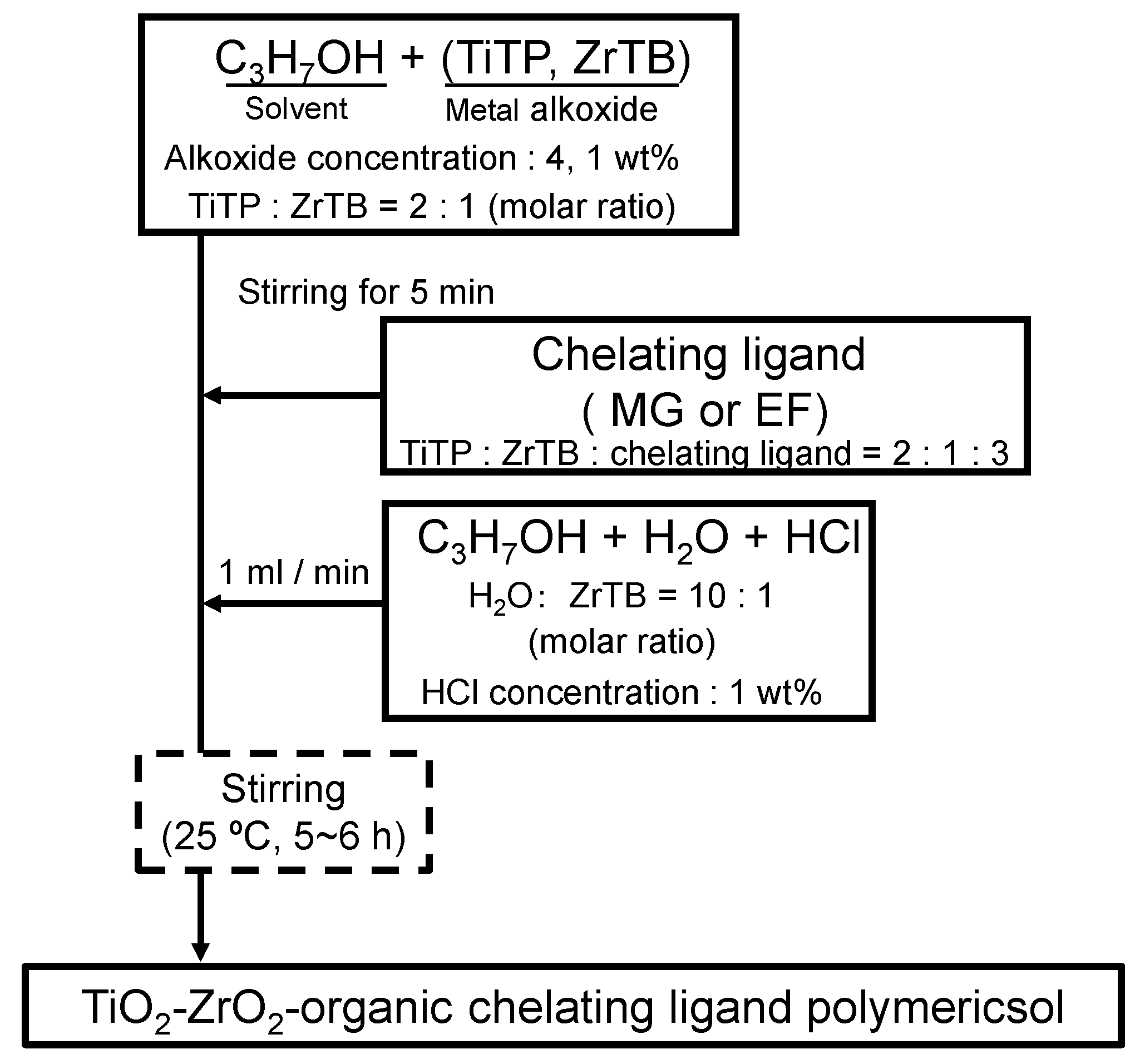
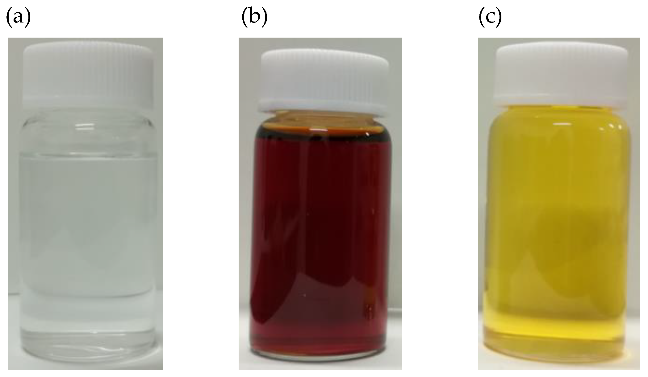
2.1. Preparation of TiO2-ZrO2 Composite Sols, Gels and Powder Samples
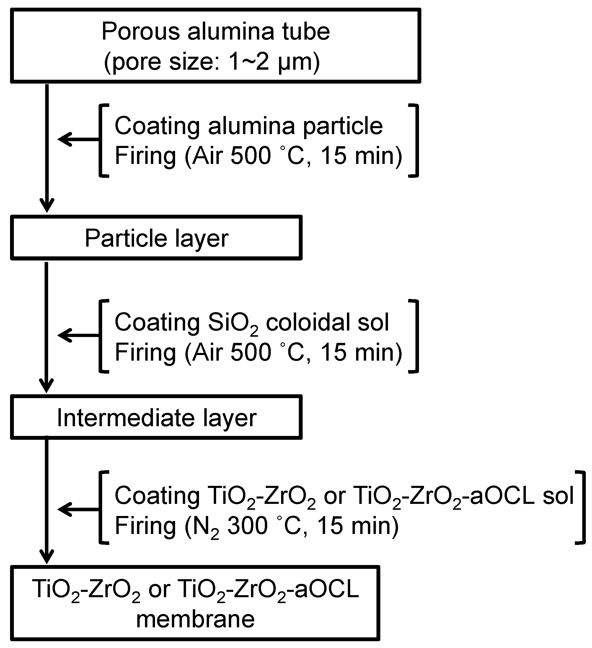
2.2. Preparation of TiO2-ZrO2 Composite Membranes
2.3. Characterization of a TiO2-ZrO2 Composite Sol and Gel Powder Samples
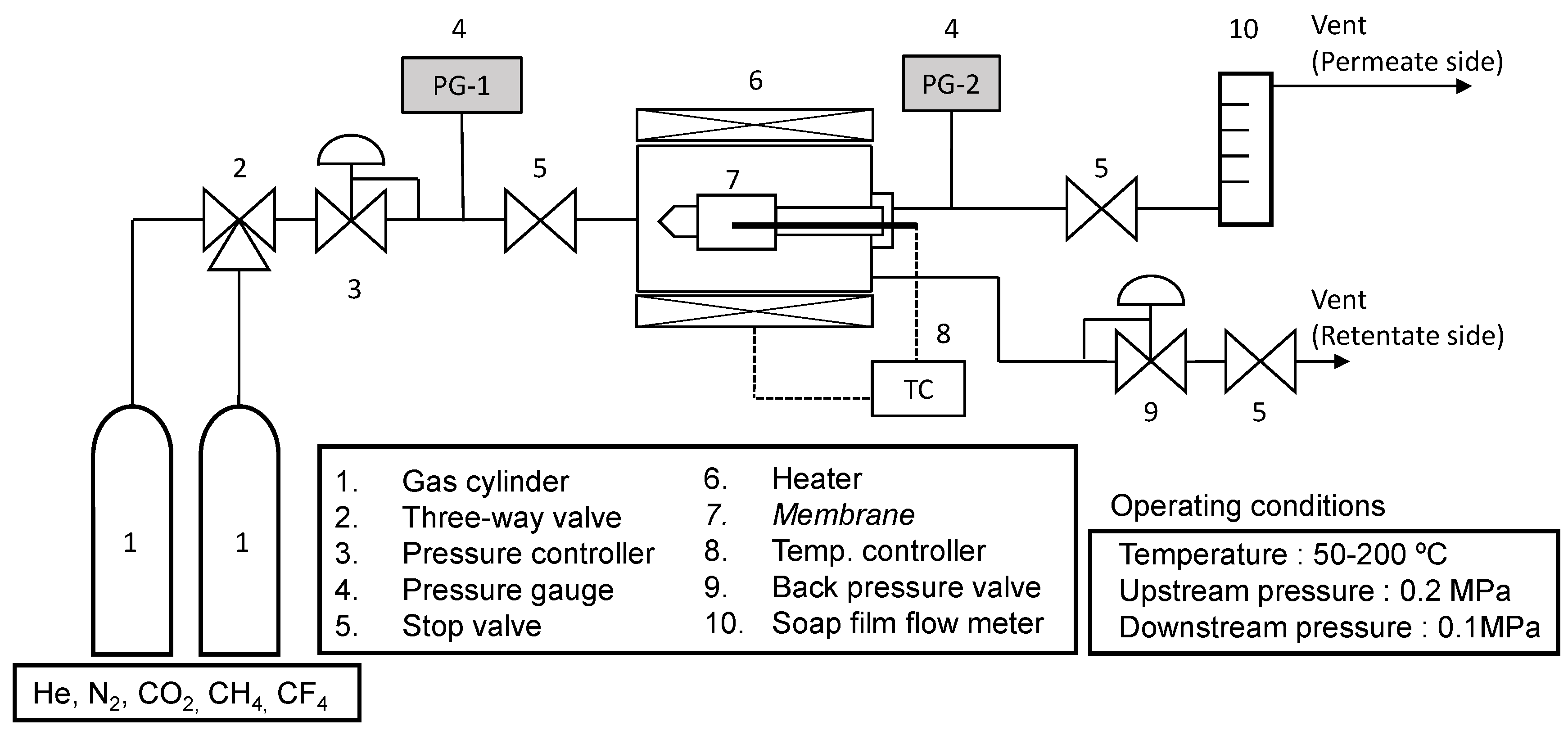
2.4. Characterization and Gas Permeation Measurement of TiO2-ZrO2-OCL Composite Membranes
3. Results and Discussion
3.1. Characterization of TiO2-ZrO2 Gel and Powder Samples
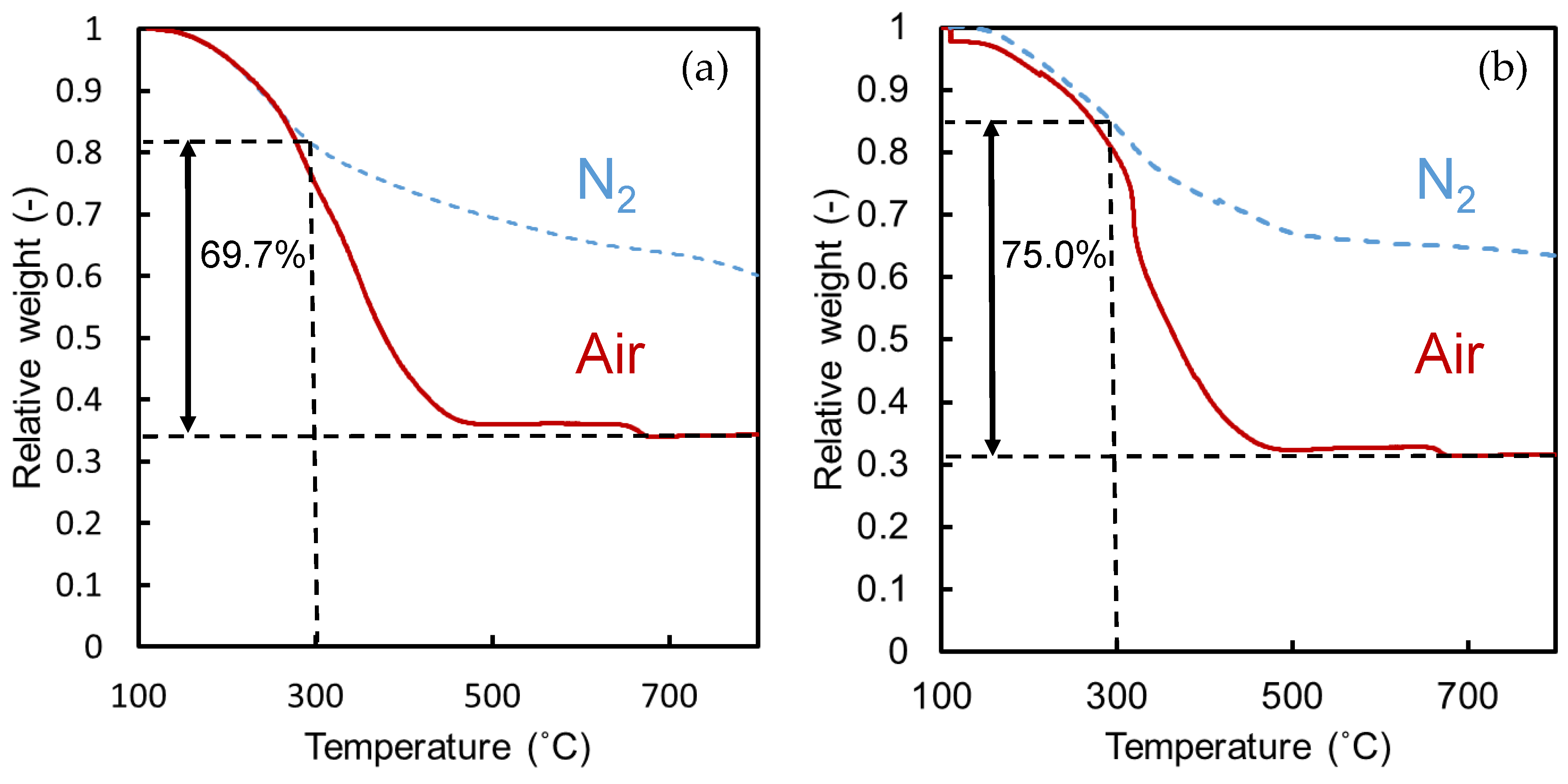
3.1.1. Thermogravimetric Analysis
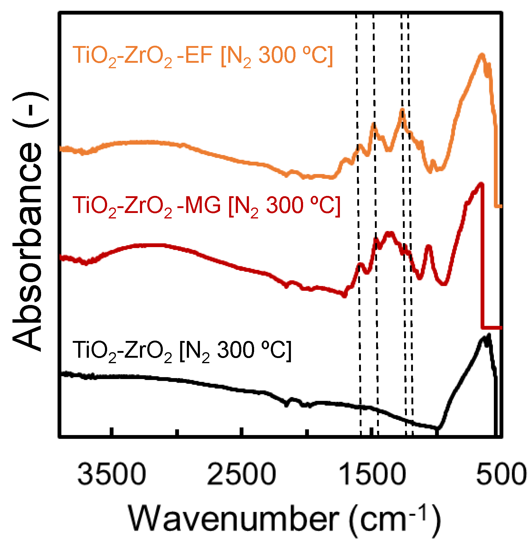
3.1.2. IR Analysis
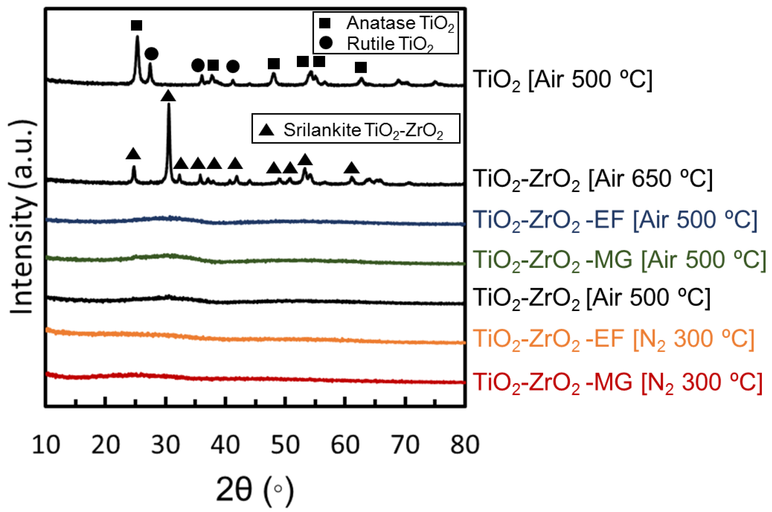
3.1.3. XRD Analysis
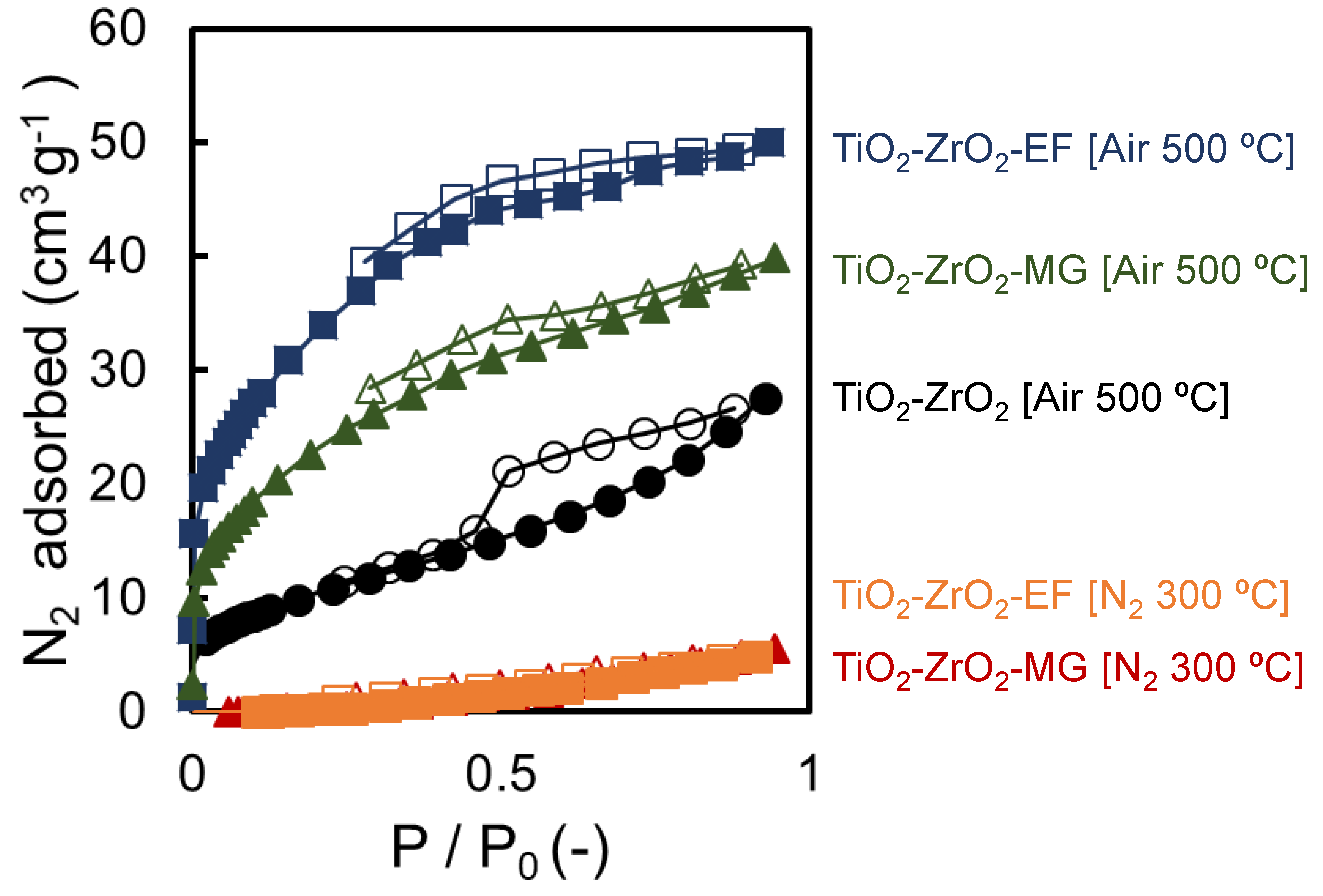
3.1.4. Nitrogen Adsorption and Desorption
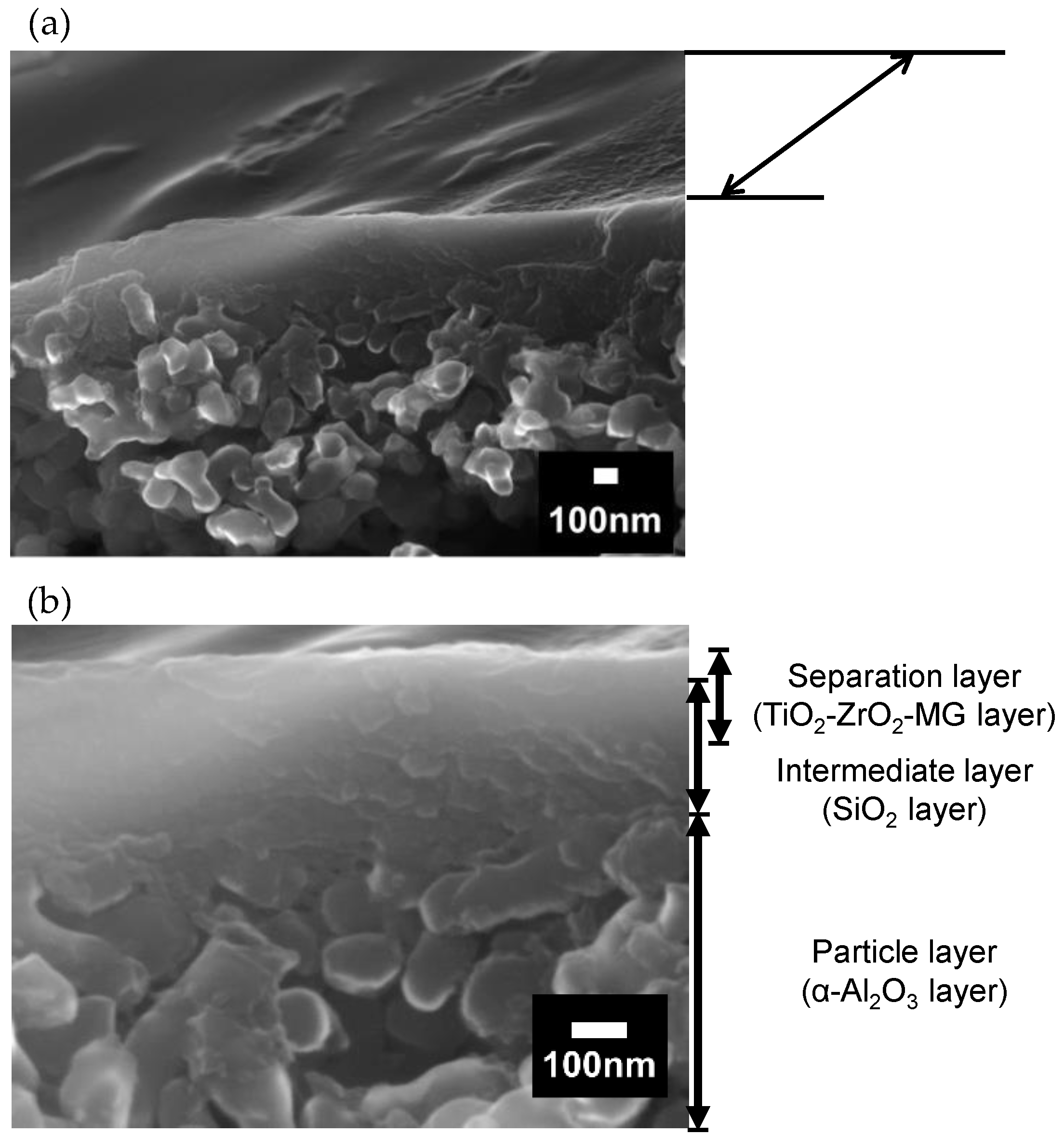
3.1.5. SEM Observation
3.2. Characterization of the SiO2 Intermediate Layer and TiO2-ZrO2 Composite Membranes
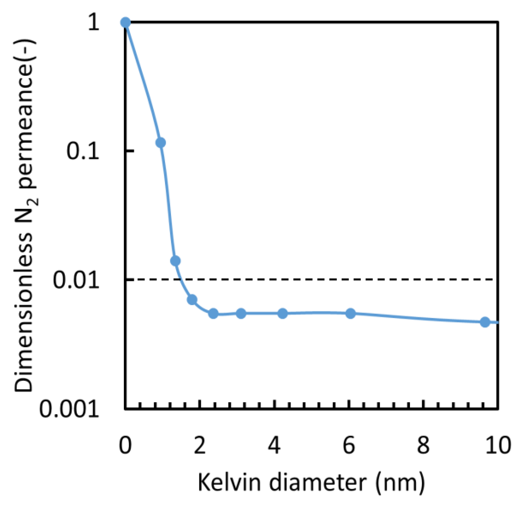
3.2.1. Intermediate Layer
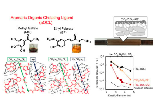
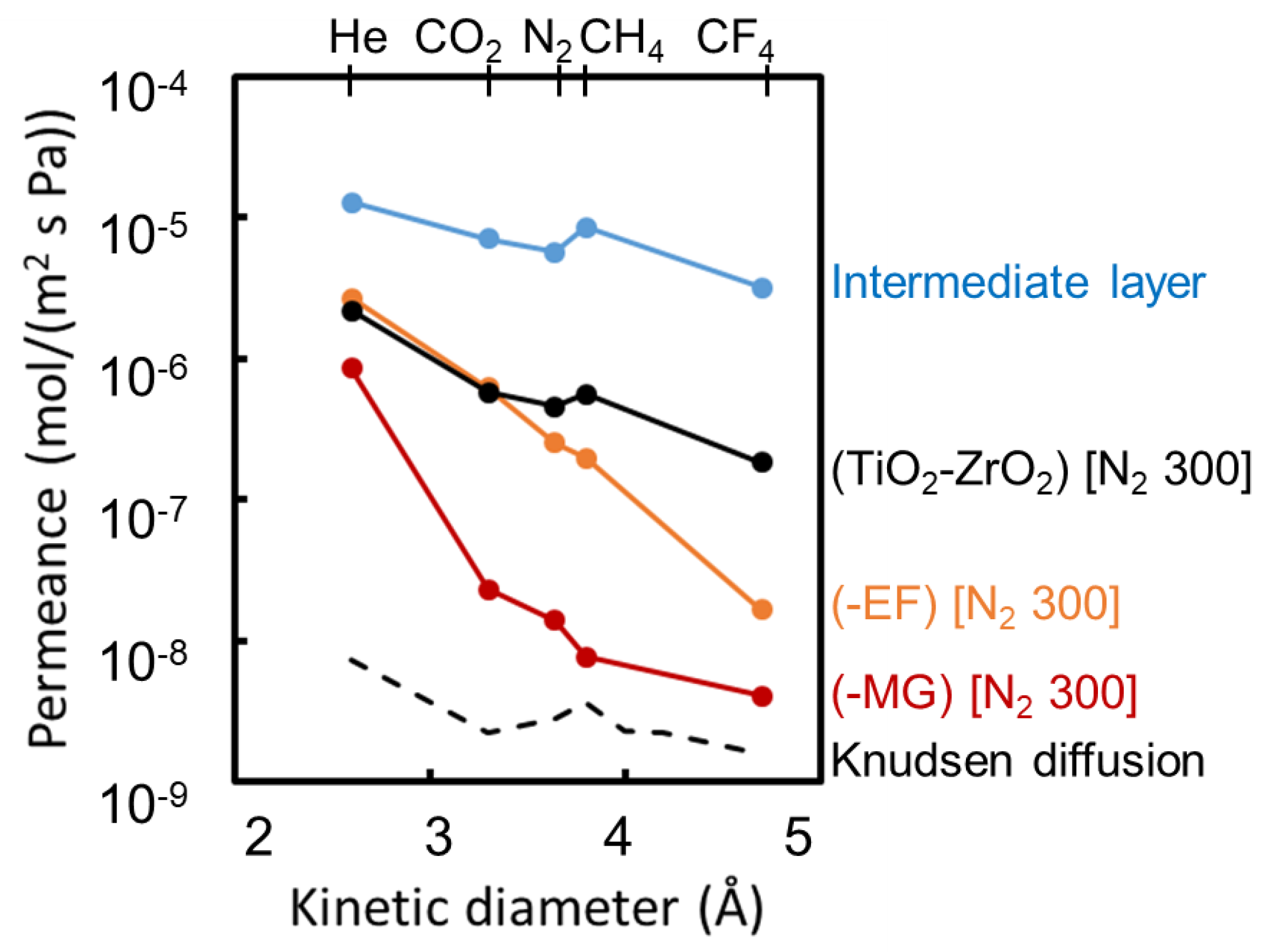
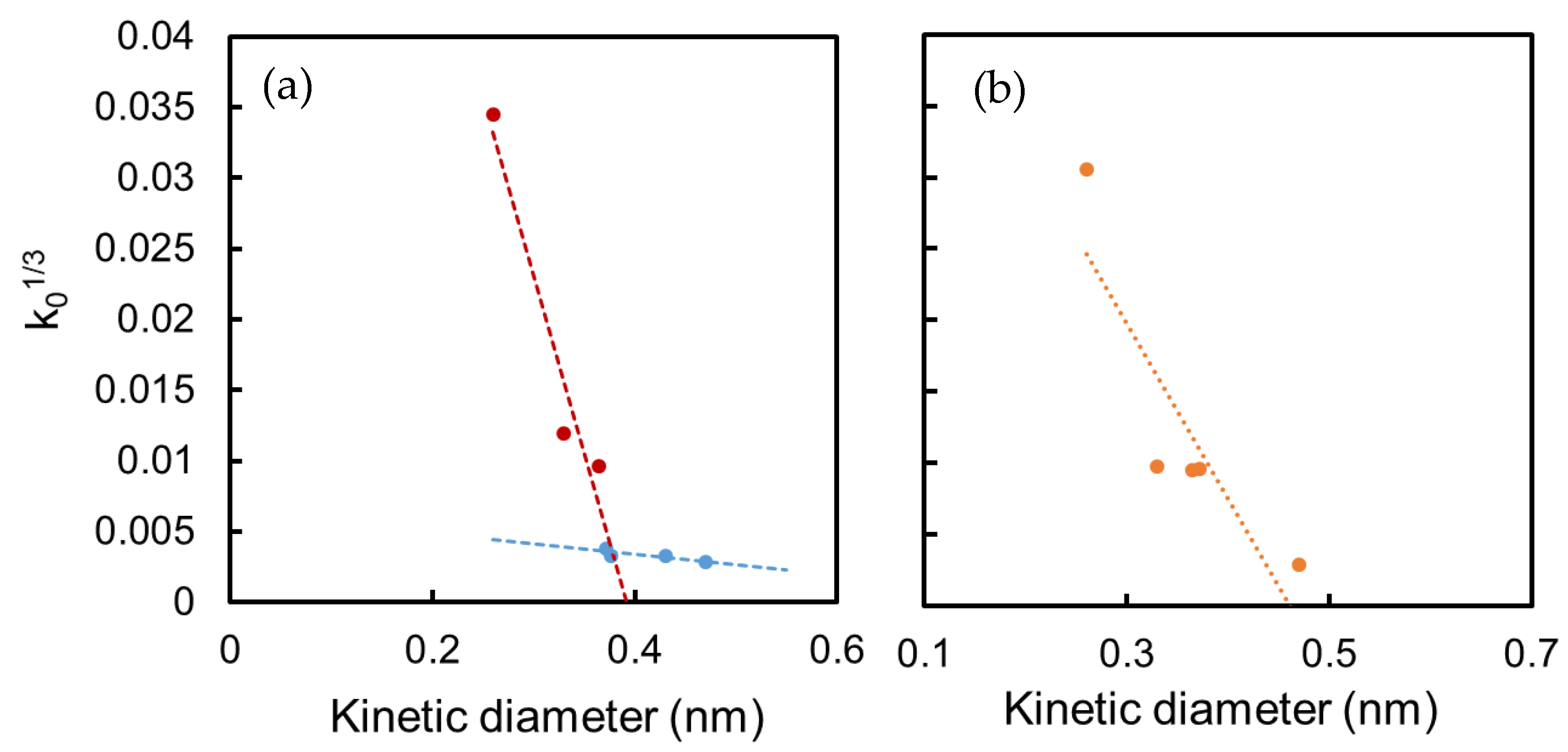
3.2.2. Kinetic Diameter Dependency of Gas Permeance at 200 °C
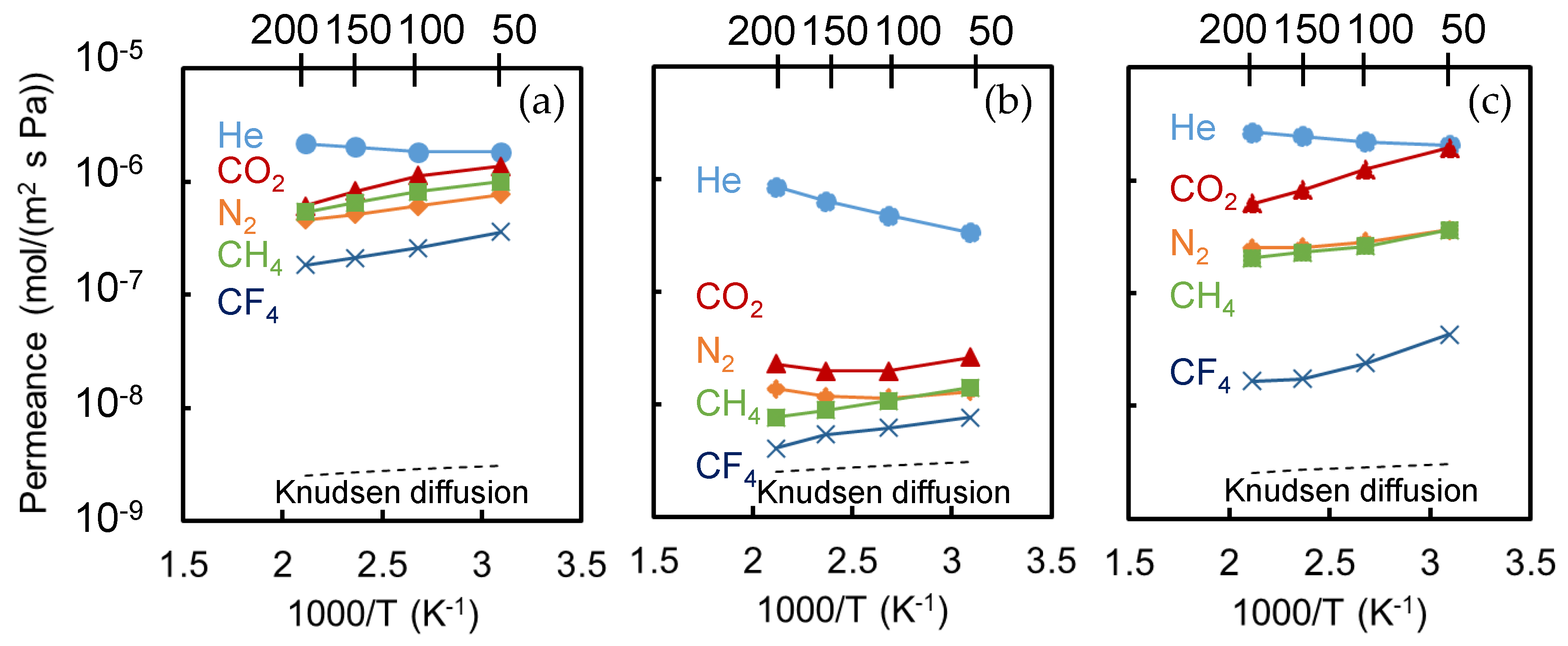
3.2.3. Temperature Dependence of Gas Permeance
4. Conclusions
Supplementary Materials
Author Contributions
Funding
Conflicts of Interest
References
- Sholl, D.S.; Lively, R.P. Seven chemical separations to change the world. Nature 2016, 532, 435–437. [Google Scholar] [CrossRef] [PubMed]
- Bernardo, P.; Drioli, E.; Golemme, G. Membrane gas separation: A Review/State of the Art. Ind. Eng. Chem. Res. 2009, 48, 4638–4663. [Google Scholar] [CrossRef]
- Harmsen, G.J. Reactive distillation: The front-runner of industrial process intensification. Chem. Eng. Process. Process Intensif. 2007, 46, 774–780. [Google Scholar] [CrossRef] [Green Version]
- Olajire, A.A. CO2 capture and separation technologies for end-of-pipe applications—A review. Energy 2010, 35, 2610–2628. [Google Scholar] [CrossRef]
- Dawson, R.; Stöckel, E.; Holst, J.R.; Adams, D.J.; Cooper, A.I. Microporous organic polymers for carbon dioxide capture. Energy Environ. Sci. 2011, 4, 4239. [Google Scholar] [CrossRef]
- Terrien, P.; Lockwood, F.; Granados, L.; Morel, T. CO2 capture from H2 plants: Implementation for EOR. Energy Procedia 2014, 63, 7861–7866. [Google Scholar] [CrossRef] [Green Version]
- Vivo-Vilches, J.F.; Carrasco-Marín, F.; Pérez-Cadenas, A.F.; Maldonado-Hódar, F.J. Fitting the porosity of carbon xerogel by CO2 activation to improve the TMP/n-octane separation. Microporous Mesoporous Mater. 2015, 209, 10–17. [Google Scholar] [CrossRef]
- Safarik, D.J.; Eldridge, R.B. Olefin/Paraffin separations by reactive absorption: A review. Ind. Eng. Chem. Res. 1998, 37, 2571–2581. [Google Scholar] [CrossRef]
- Sanders, D.F.; Smith, Z.P.; Guo, R.; Robeson, L.M.; McGrath, J.E.; Paul, D.R.; Freeman, B.D. Energy-efficient polymeric gas separation membranes for a sustainable future: A review. Polymer (Guildf) 2013, 54, 4729–4761. [Google Scholar] [CrossRef] [Green Version]
- Kovvali, A.S.; Sirkar, K.K. Dendrimer liquid membranes: CO2 separation from gas mixtures. Ind. Eng. Chem. Res. 2001, 40, 2502–2511. [Google Scholar] [CrossRef]
- Van Gestel, T. Corrosion properties of alumina and titania NF membranes. J. Membr. Sci. 2003, 214, 21–29. [Google Scholar] [CrossRef]
- Khatib, S.J.; Oyama, S.T. Silica membranes for hydrogen separation prepared by chemical vapor deposition (CVD). Sep. Purif. Technol. 2013, 111, 20–42. [Google Scholar] [CrossRef]
- Tsuru, T. Silica-based membranes with molecular-net-sieving properties: Development and applications. J. Chem. Eng. Jpn. 2018, 51, 713–725. [Google Scholar] [CrossRef] [Green Version]
- Ahn, S.-J.; Takagaki, A.; Sugawara, T.; Kikuchi, R.; Oyama, S.T. Permeation properties of silica-zirconia composite membranes supported on porous alumina substrates. J. Membr. Sci. 2017, 526, 409–416. [Google Scholar] [CrossRef]
- Kanezashi, M.; Murata, M.; Nagasawa, H.; Tsuru, T. Fluorine doping of microporous organosilica membranes for pore size control and enhanced hydrophobic properties. ACS Omega 2018, 3, 8612–8620. [Google Scholar] [CrossRef] [PubMed]
- Caro, J.; Noack, M.; Kölsch, P.; Schäfer, R. Zeolite membranes—state of their development and perspective. Microporous Mesoporous Mater. 2000, 38, 3–24. [Google Scholar] [CrossRef]
- Li, J.-R.; Kuppler, R.J.; Zhou, H.-C. Selective gas adsorption and separation in metal–organic frameworks. Chem. Soc. Rev. 2009, 38, 1477. [Google Scholar] [CrossRef]
- Caro, J.; Noack, M. Zeolite membranes—Recent developments and progress. Microporous Mesoporous Mater. 2008, 115, 215–233. [Google Scholar] [CrossRef]
- Stock, N.; Biswas, S. Synthesis of Metal-Organic Frameworks (MOFs): Routes to various MOF topologies, morphologies, and composites. Chem. Rev. 2012, 112, 933–969. [Google Scholar] [CrossRef]
- Tsuru, T.; Wada, S.; Izumi, S.; Asaeda, M. Silica-zirconia membranes for nanofiltration. J. Membr. Sci. 1998, 149, 127–135. [Google Scholar] [CrossRef]
- Tsuru, T.; Hironaka, D.; Yoshioka, T.; Asaeda, M. Titania membranes for liquid phase separation: Effect of surface charge on flux. Sep. Purif. Technol. 2001, 25, 307–314. [Google Scholar] [CrossRef]
- Aust, U.; Benfer, S.; Dietze, M.; Rost, A.; Tomandl, G. Development of microporous ceramic membranes in the system TiO2/ZrO2. J. Memb. Sci. 2006, 281, 463–471. [Google Scholar] [CrossRef]
- Anisah, S.; Kanezashi, M.; Nagasawa, H.; Tsuru, T. TiO2-ZrO2 membranes of controlled pore sizes with different Ti/Zr ratios for nanofiltration. J. Sol-Gel Sci. Technol. 2019, 92, 12–24. [Google Scholar] [CrossRef]
- Bosch, P.; Lara, V.H. Influence of isoeugenol as a chelating agent on the structure of Si-Ti polymeric systems obtained from alkoxides. J. Non-Cryst. Solids. 1999, 248, 147–158. [Google Scholar] [CrossRef]
- Spijksma, G.I.; Bouwmeester, H.J.M.; Blank, D.H.A.; Kessler, V.G. Stabilization and destabilization of zirconium propoxide precursors by acetylacetone. Chem. Commun. 2004, 10, 1874–1875. [Google Scholar] [CrossRef] [PubMed]
- Benfer, S.; Popp, U.; Richter, H.; Siewert, C.; Tomandl, G. Development and characterization of ceramic nanofiltration membranes. Sep. Purif. Technol. 2001, 22–23, 231–237. [Google Scholar] [CrossRef]
- Van Gestel, T.; Sebold, D.; Kruidhof, H.; Bouwmeester, H.J.M. ZrO2 and TiO2 membranes for nanofiltration and pervaporation. Part 2. Development of ZrO2 and TiO2 toplayers for pervaporation. J. Membr. Sci. 2008, 318, 413–421. [Google Scholar] [CrossRef]
- Sada, Y.; Yoshioka, T.; Nakagawa, K.; Shintani, T.; Iesako, R.; Kamio, E.; Matsuyama, H. Preparation and characterization of organic chelate ligand (OCL) -templated TiO2–ZrO2 nanofiltration membranes. J. Membr. Sci. 2019, 591, 117304. [Google Scholar] [CrossRef]
- Feuston, B.P.; Garofalini, S.H. Empirical three-body potential for vitreous silica. J. Chem. Phys. 1988, 89, 5818–5824. [Google Scholar] [CrossRef]
- Yoshioka, T.; Tsuru, T.; Asaeda, M. Molecular dynamics study of gas permeation through amorphous silica network and inter-particle pores on microporous silica membranes. Mol. Phys. 2004, 102, 191–202. [Google Scholar] [CrossRef]
- Yoshioka, T.; Asaeda, M.; Tsuru, T. A molecular dynamics simulation of pressure-driven gas permeation in a micropore potential field on silica membranes. J. Membr. Sci. 2007, 293, 81–93. [Google Scholar] [CrossRef] [Green Version]
- Spijksma, G.I.; Huiskes, C.; Benes, N.E.; Kruidhof, H.; Blank, D.H.A.; Kessler, V.G.; Bouwmeester, H.J.M. Microporous zirconia–titania composite membranes derived from diethanolamine-modified precursors. Adv. Mater. 2006, 18, 2165–2168. [Google Scholar] [CrossRef]
- Fukumoto, T.; Yoshioka, T.; Nagasawa, H.; Kanezashi, M.; Tsuru, T. Development and gas permeation properties of microporous amorphous TiO2–ZrO2–organic composite membranes using chelating ligands. J. Membr. Sci. 2014, 461, 96–105. [Google Scholar] [CrossRef]
- Omae, I. Applications of six-membered ring products from cyclometalation reactions. J. Organomet. Chem. 2017, 848, 184–195. [Google Scholar] [CrossRef]
- Anisah, S.; Puthai, W.; Kanezashi, M.; Nagasawa, H.; Tsuru, T. Preparation, characterization, and evaluation of TiO2-ZrO2 nanofiltration membranes fired at different temperatures. J. Membr. Sci. 2018, 564, 691–699. [Google Scholar] [CrossRef]
- Yoshioka, T.; Nakanishi, E.; Tsuru, T.; Asaeda, M. Experimental study of gas permeation through microporous silica membranes. AIChE J. 2001, 47, 2052–2063. [Google Scholar] [CrossRef]
- Tsuru, T.; Hino, T.; Yoshioka, T.; Asaeda, M. Permporometry characterization of microporous ceramic membranes. J. Membr. Sci. 2001, 186, 257–265. [Google Scholar] [CrossRef]
- Li, M.; Li, X.; Jiang, G.; He, G. Hierarchically macro–mesoporous ZrO2–TiO2 composites with enhanced photocatalytic activity. Ceram. Int. 2015, 41, 5749–5757. [Google Scholar] [CrossRef]
- Troitzsch, U.; Christy, A.G.; Ellis, D.J. The crystal structure of disordered (Zr,Ti)O2 solid solution including srilankite: Evolution towards tetragonal ZrO2 with increasing Zr. Phys. Chem. Miner. 2005, 32, 504–514. [Google Scholar] [CrossRef]
- Robeson, L.M. The upper bound revisited. J. Membr. Sci. 2008, 320, 390–400. [Google Scholar] [CrossRef]
- Niimi, T.; Nagasawa, H.; Kanezashi, M.; Yoshioka, T.; Ito, K.; Tsuru, T. Preparation of BTESE-derived organosilica membranes for catalytic membrane reactors of methylcyclohexane dehydrogenation. J. Membr. Sci. 2014, 455, 375–383. [Google Scholar] [CrossRef]
- Kanezashi, M.; Fujita, T.; Asaeda, M. Nickel-doped silica membranes for separation of helium from organic gas mixtures. Sep. Sci. Technol. 2005, 40, 225–233. [Google Scholar] [CrossRef]
- Kadioglu, O.; Keskin, S. Efficient separation of helium from methane using MOF membranes. Sep. Purif. Technol. 2018, 191, 192–199. [Google Scholar] [CrossRef]
- Xiao, J.; Wei, J. Diffusion mechanism of hydrocarbons in zeolites-I. Theory. Chem Eng. Sci. 1992, 47, 1123–1141. [Google Scholar] [CrossRef]
- Yoshioka, T.; Kanezashi, M.; Tsuru, T. Micropore size estimation on gas separation membranes: A study in experimental and molecular dynamics. AIChE J. 2013, 59, 2179–2194. [Google Scholar] [CrossRef]
- Chesson, A.; Provan, G.J.; Russell, W.R.; Scobbie, L.; Richardson, A.J.; Stewart, C. Hydroxycinnamic acids in the digestive tract of livestock and humans. J. Sci. Food Agric. 1999, 79, 373–378. [Google Scholar] [CrossRef]
- Ward, G.; Hadar, Y.; Bilkis, I.; Konstantinovsky, L.; Dosoretz, C.G. Initial steps of ferulic acid polymerization by lignin peroxidase. J. Biol. Chem. 2001, 276, 18734–18741. [Google Scholar] [CrossRef] [Green Version]
- Sunarso, J.; Hashim, S.S.; Lin, Y.S.; Liu, S.M. Membranes for helium recovery: An overview on the context, materials and future directions. Sep. Purif. Technol. 2017, 176, 335–383. [Google Scholar] [CrossRef]


| wt% | Sol Type | Chelating Ligand | 1-PrOH (g) | ZrTB (g) | TiTP (g) | H2O (g) | HCl (g) | Chelating Ligand (g) |
|---|---|---|---|---|---|---|---|---|
| 1.0 | Polymer | Non | 58.70 | 0.27 | 0.33 | 0.10 | 0.60 | 0 |
| 1.0 | Polymer | MG | 58.42 | 0.27 | 0.33 | 0.10 | 0.60 | 0.28 |
| 1.0 | Polymer | EF | 58.47 | 0.27 | 0.33 | 0.10 | 0.60 | 0.23 |
| Sample | Adsorbed Amount (cm3/g) | BET Surface Area (m2/g) |
|---|---|---|
| TiO2-ZrO2 | 27.6 | 34.9 |
| TiO2-ZrO2-MG | 39.9 | 72.2 |
| TiO2-ZrO2-EF | 50.0 | 104 |
| Intermediate Layer for | Mean Pore Size (nm) | Leakage Ratio (Kelvin Diameter) | Dry N2 Permeance (10−6 mol/(m2 s Pa)) |
|---|---|---|---|
| TiO2-ZrO2-MG | 0.5–1 | 0.41% (9.64 nm) | 4.91 |
| TiO2-ZrO2-EF | 0.5–1 | 0.47% (9.64 nm) | 4.97 |
| Membrane | Permeance Ratio [–] | |||
|---|---|---|---|---|
| He/CF4 | CO2/N2 | He/N2 | He/CH4 | |
| TiO2-ZrO2 | 11.7 | 1.26 | 4.73 | 3.88 |
| TiO2-ZrO2-MG | 209 | 1.66 | 61.7 | 111 |
| TiO2-ZrO2-EF | 163 | 2.47 | 10.6 | 13.6 |
| Membrane | EP in Equation (1) [kJ/mol] | ||||
|---|---|---|---|---|---|
| He | CO2 | N2 | CH4 | CF4 | |
| TiO2-ZrO2-MG | 9.9 | 6.7 | 7.1 | −1.0 | −4.5 |
| TiO2-ZrO2-EF | 3.9 | −8.5 | −3.5 | −2.5 | −9.0 |
Publisher’s Note: MDPI stays neutral with regard to jurisdictional claims in published maps and institutional affiliations. |
© 2020 by the authors. Licensee MDPI, Basel, Switzerland. This article is an open access article distributed under the terms and conditions of the Creative Commons Attribution (CC BY) license (http://creativecommons.org/licenses/by/4.0/).
Share and Cite
Tachibana, T.; Yoshioka, T.; Nakagawa, K.; Shintani, T.; Kamio, E.; Matsuyama, H. Gas Permeation Characteristics of TiO2-ZrO2-Aromatic Organic Chelating Ligand (aOCL) Composite Membranes. Membranes 2020, 10, 388. https://0-doi-org.brum.beds.ac.uk/10.3390/membranes10120388
Tachibana T, Yoshioka T, Nakagawa K, Shintani T, Kamio E, Matsuyama H. Gas Permeation Characteristics of TiO2-ZrO2-Aromatic Organic Chelating Ligand (aOCL) Composite Membranes. Membranes. 2020; 10(12):388. https://0-doi-org.brum.beds.ac.uk/10.3390/membranes10120388
Chicago/Turabian StyleTachibana, Takashi, Tomohisa Yoshioka, Keizo Nakagawa, Takuji Shintani, Eiji Kamio, and Hideto Matsuyama. 2020. "Gas Permeation Characteristics of TiO2-ZrO2-Aromatic Organic Chelating Ligand (aOCL) Composite Membranes" Membranes 10, no. 12: 388. https://0-doi-org.brum.beds.ac.uk/10.3390/membranes10120388