The Simulation and Optimization of an Electromagnetic Field in a Vertical Continuous Casting Mold for a Large Bloom

Abstract
:1. Introduction
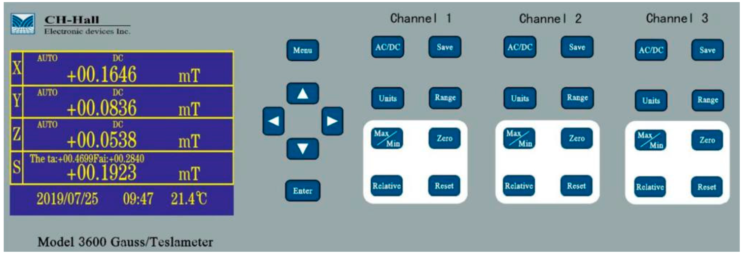
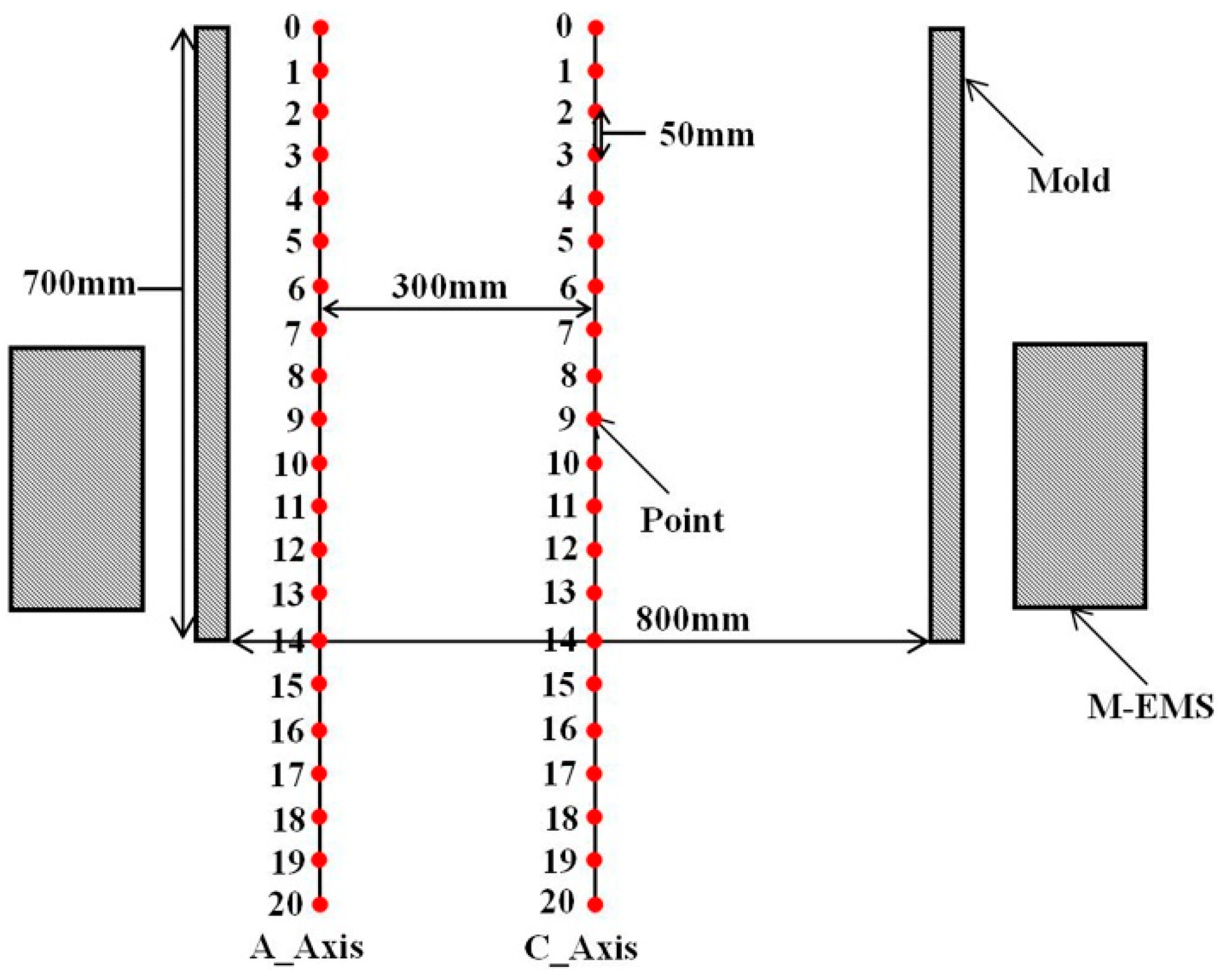
2. Magnetic Field Measurement
3. Modification of the Electromagnetic Model
3.1. Control Equations
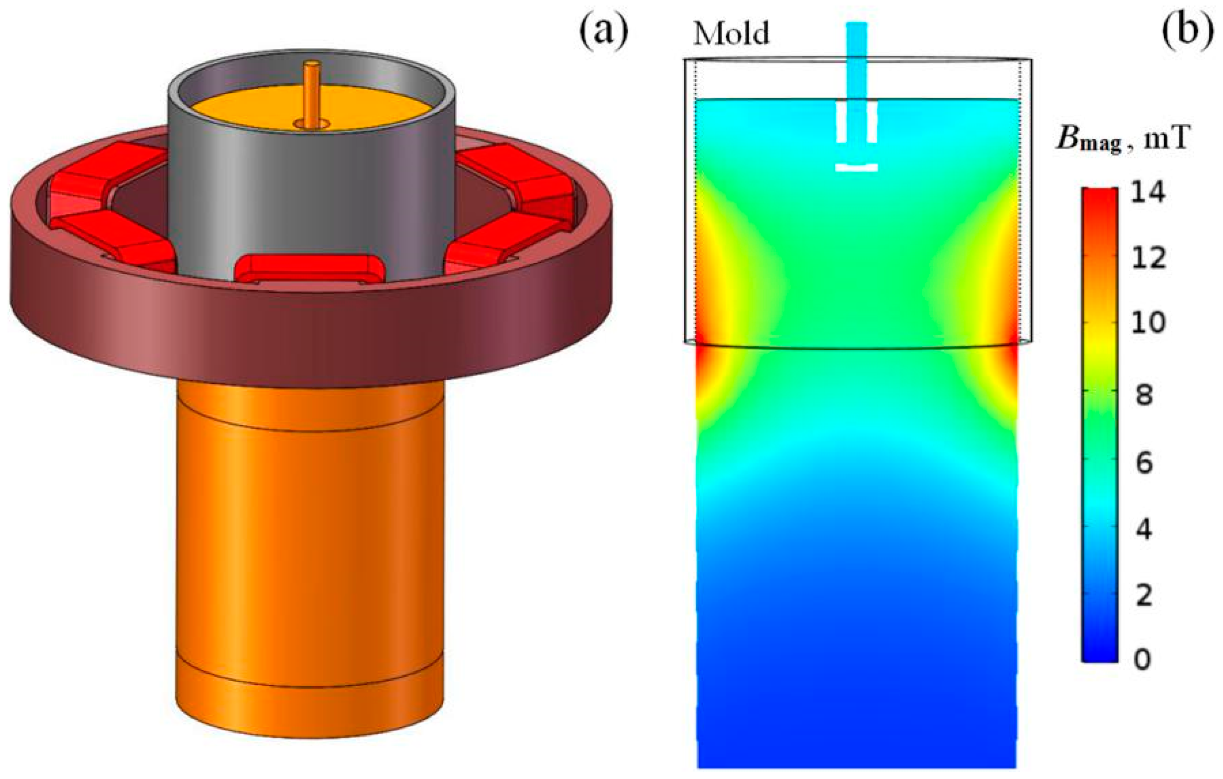
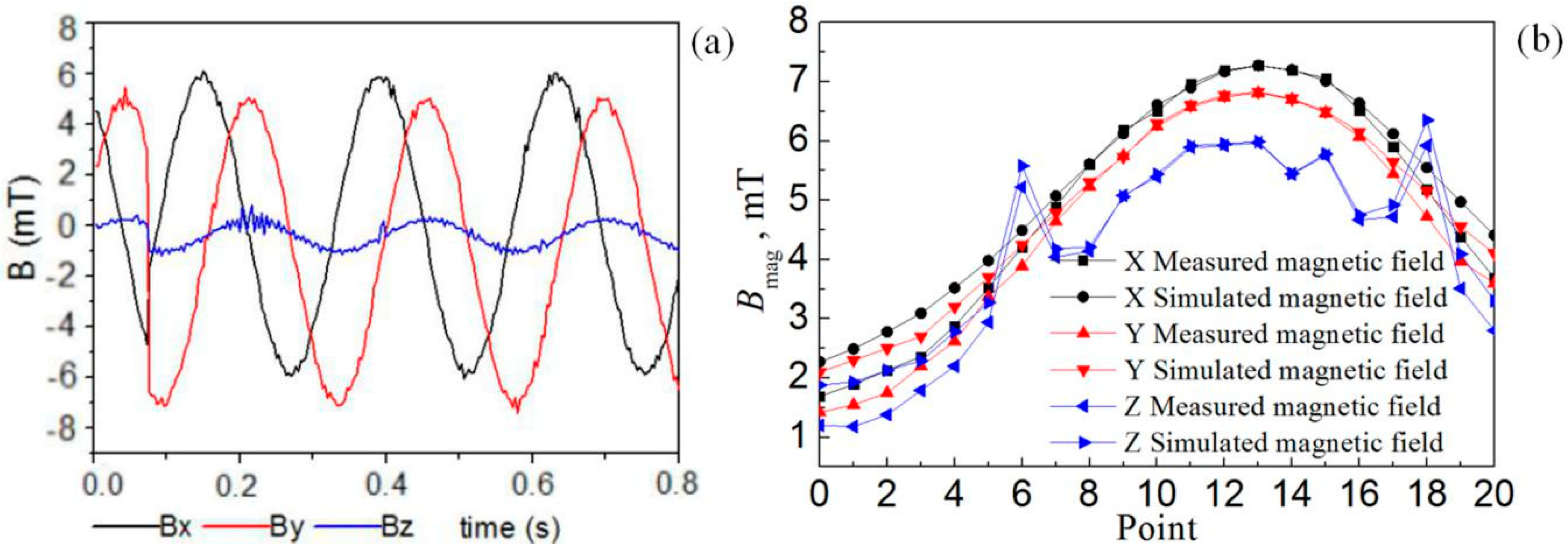
3.2. Validation of the Electromagnetic Model
4. The Influences of Electromagnetic Parameters on a Magnetic Field
4.1. The Effect of Current Frequency on the Magnetic Field
4.2. The Effect of Current Intensity on the Magnetic Field
5. Bipolar Electromagnetic Stirring
5.1. The Effect of the Current Intensity of M-EMSB on a Magnetic Field
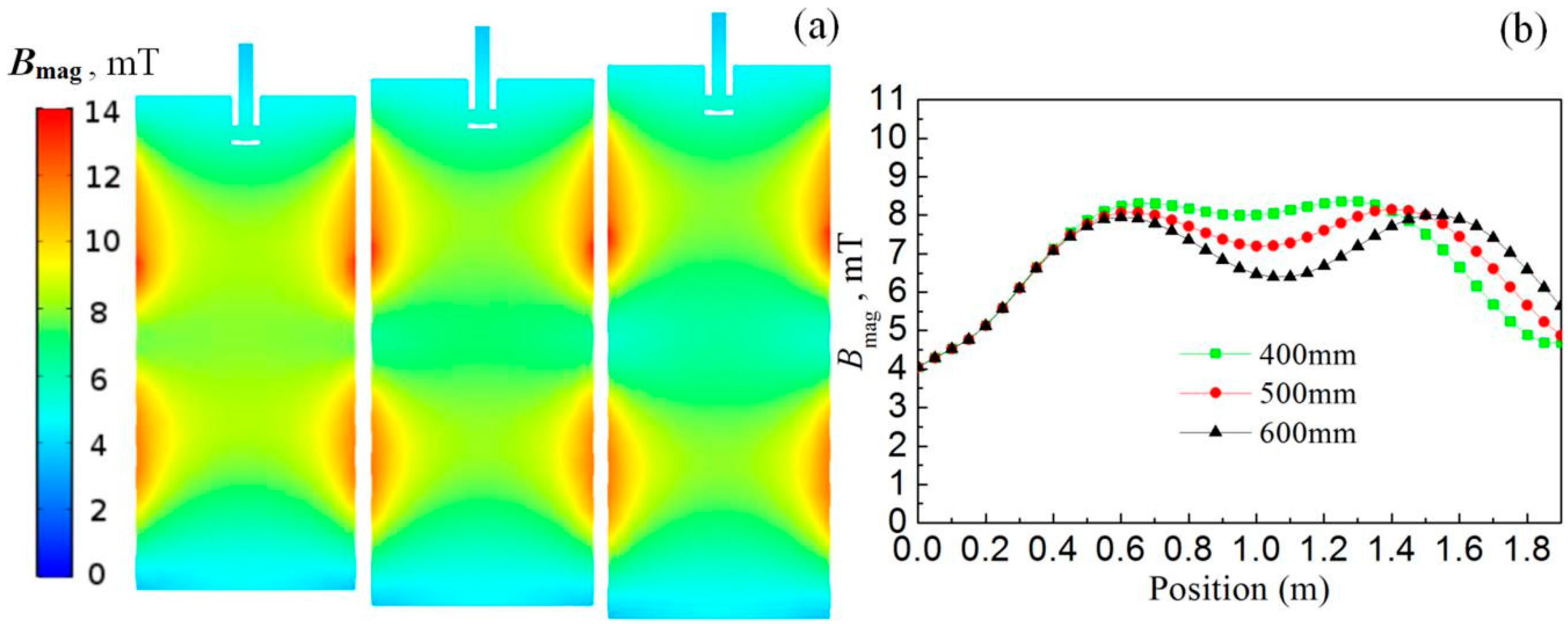
5.2. The Effect of the Distance Between the Poles on the Magnetic Field
6. Conclusions
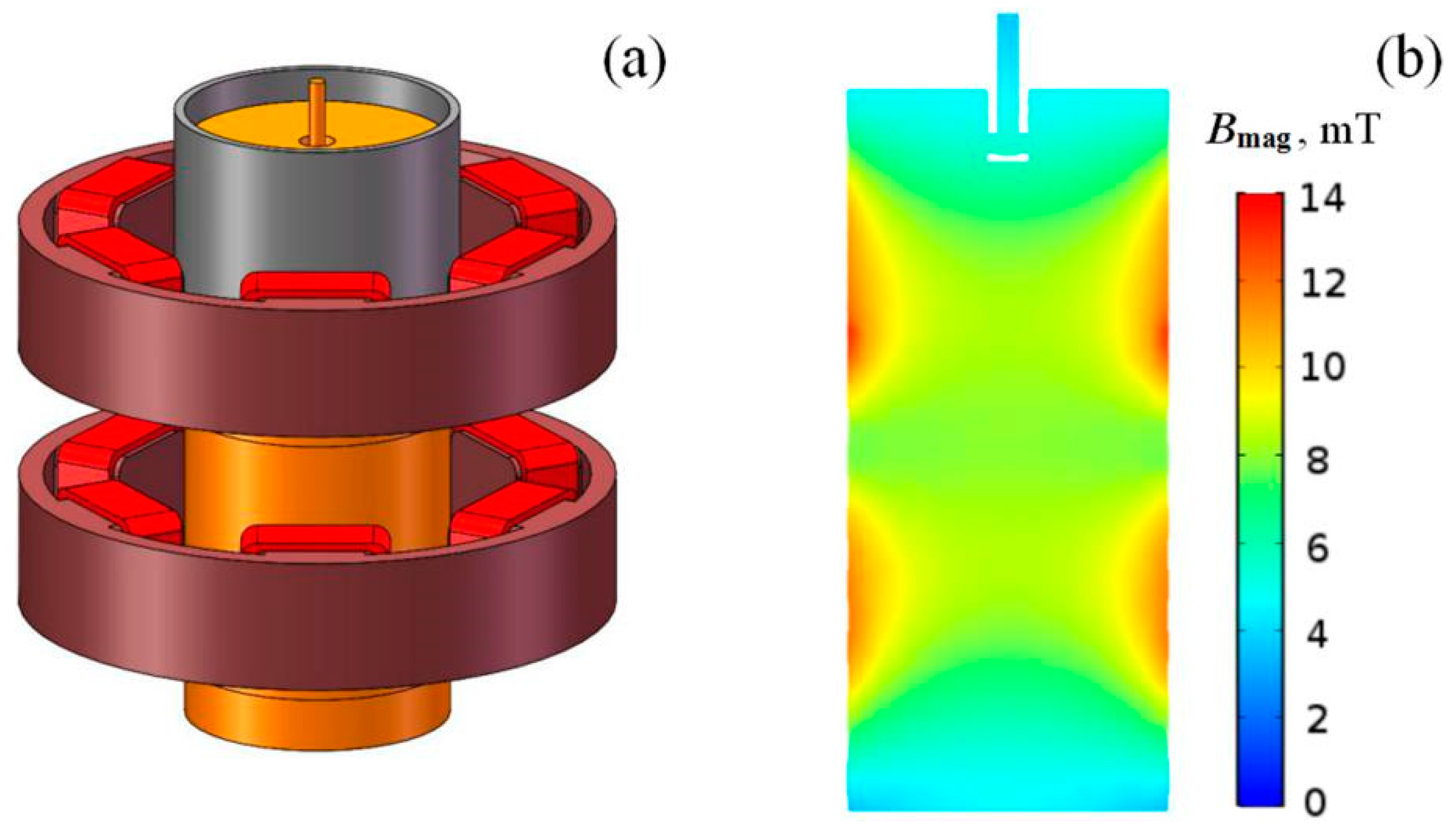
- The copper plate of the mold has a certain conductivity and certain magnetic shielding properties; the magnetic field is concentrated at the lower edge of mold; the maximum magnetic flux density is located at P14.
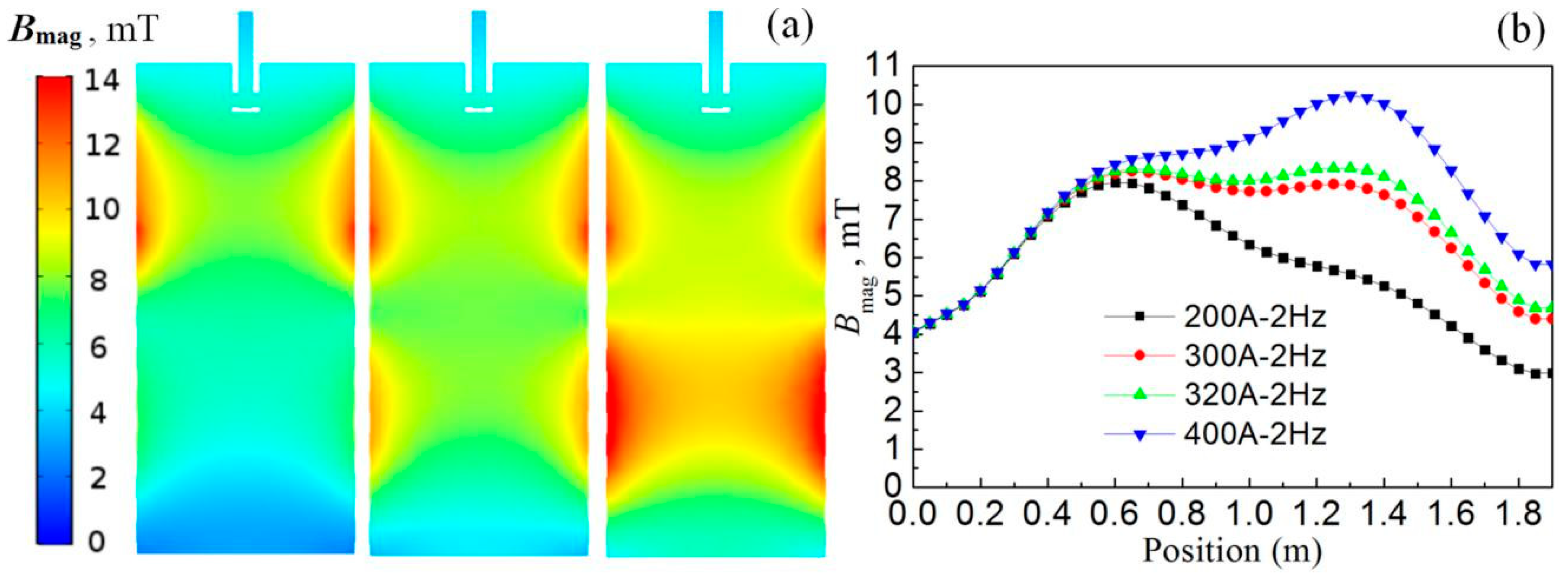
- When the current intensity of M-EMS is 400 A, the current frequency increases from 1 to 35 Hz; the electromagnetic force first increases and then decreases. When the current frequency is 9 Hz, the electromagnetic force reaches its maximum value. The electromagnetic force increases with the increase of the current intensity.
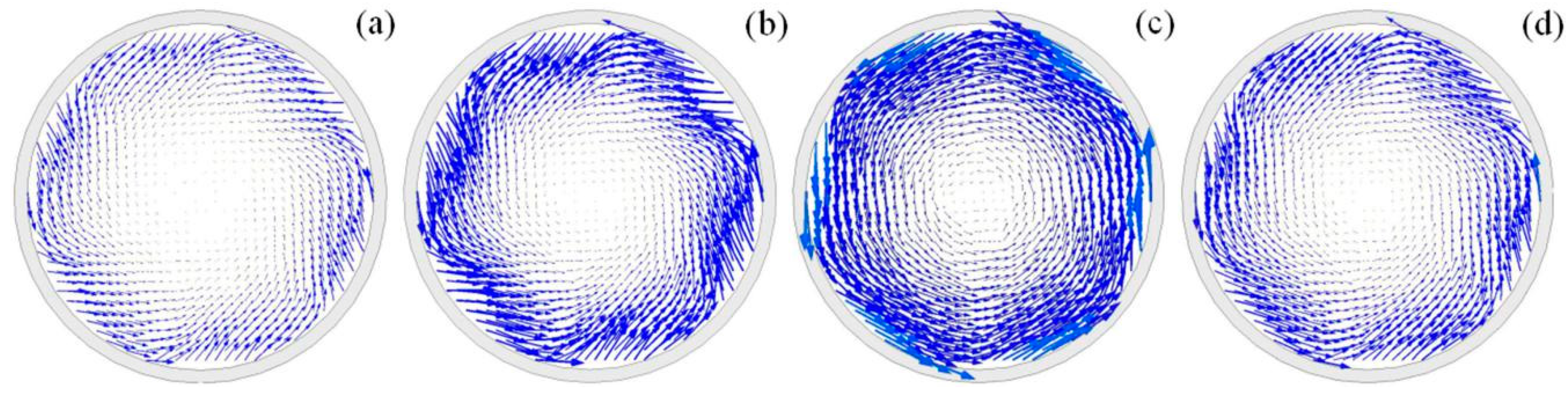
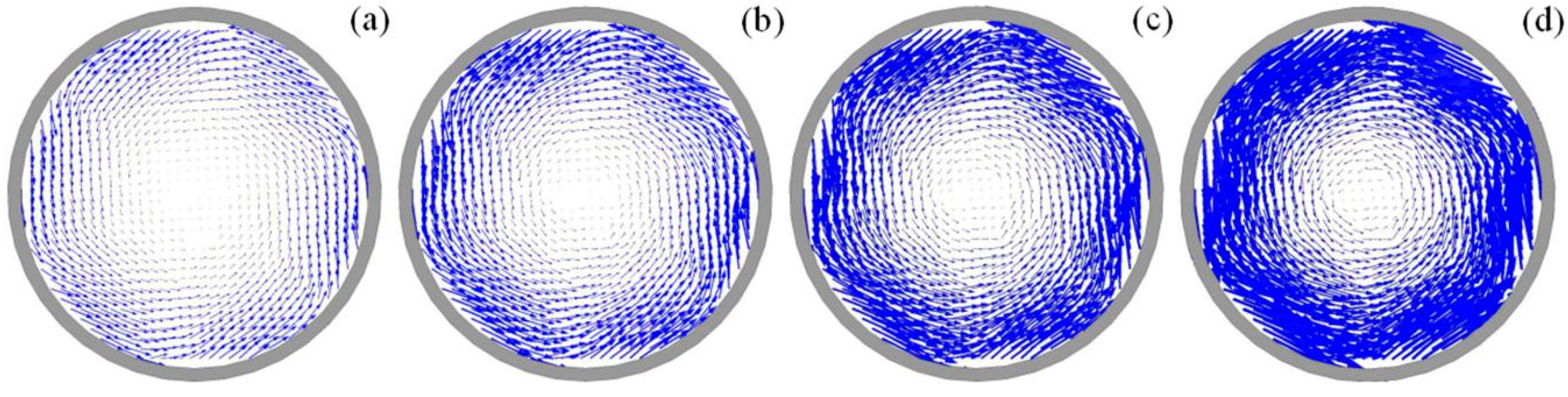
- With the increase of current intensity of M-EMSB, the internal magnetic field intensity of M-EMSA gradually increases, and the middle region is gradually filled by a magnetic field. With the increase of the distance between the poles, the low-intensity magnetic field appears at the center of the magnetic field, and the range of the low-intensity magnetic field increases with the increase of the distance.
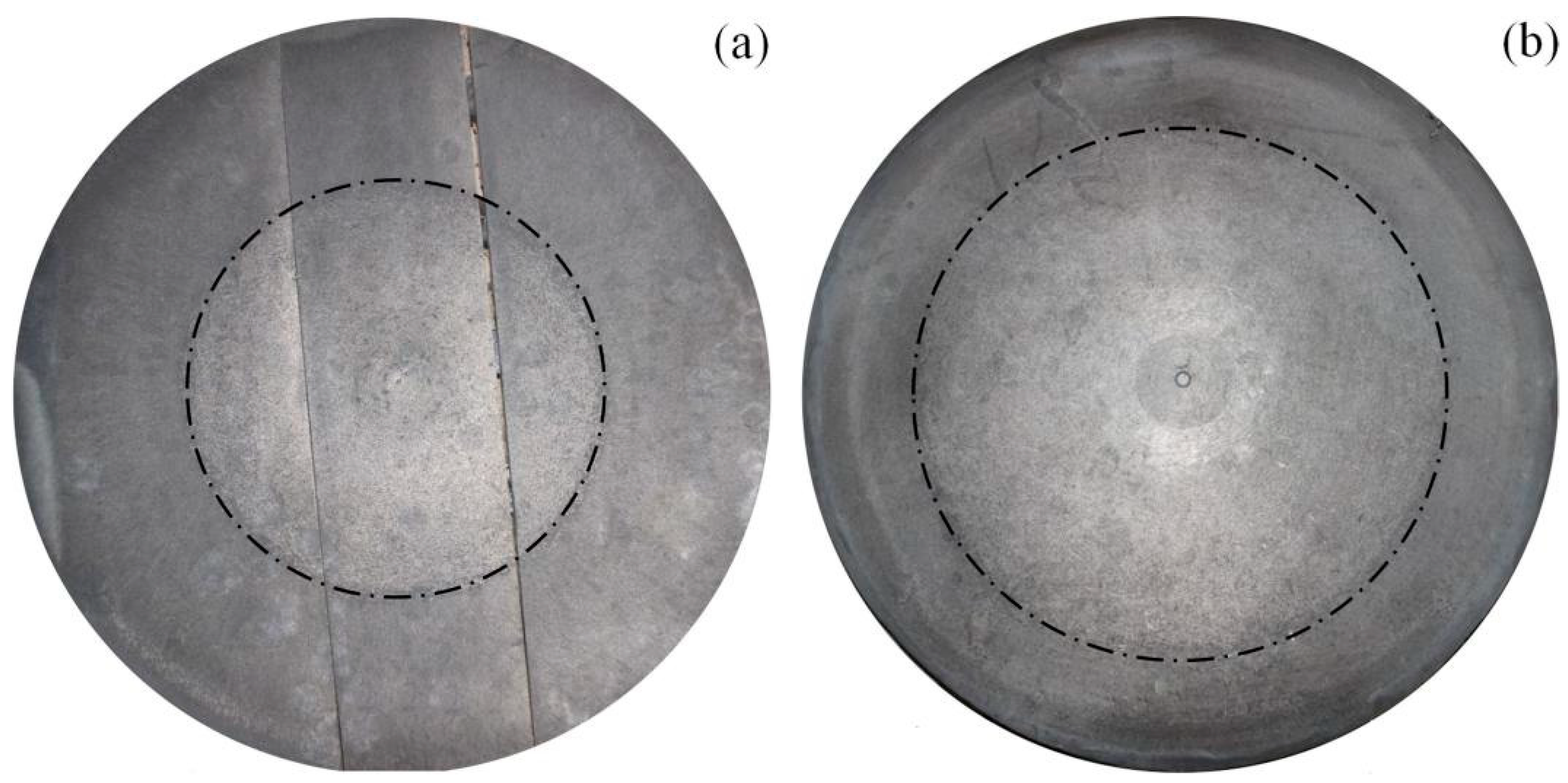
- During the production of a large bloom, it is still difficult for the electromagnetic stirring magnetic field to penetrate into the round bloom. The bipolar electromagnetic agitator technology can enhance the effect of electromagnetic stirring. Compared with the traditional continuous casting electromagnetic agitator, the center equiaxial crystal of bipolar electromagnetic agitator increases from 30.3% to 49.5%, and the internal quality of round bloom is improved obviously.
Author Contributions
Funding
Conflicts of Interest
References
- Trindade, L.B.; Vilela, A.C.F.; Filho, A.F.F. Numerical model of electromagnetic stirring for continuous casting billets. IEEE Trans. Magn. 2002, 38, 3658–3660. [Google Scholar] [CrossRef] [Green Version]
- Wang, B.; Chen, W.; Chen, Y. Coupled numerical simulation on electromagnetic field and flow field in the round billet mould with electromagnetic stirring. Ironmak. Steelmak. 2014, 42, 63–69. [Google Scholar] [CrossRef]
- Zhang, L.W.; Wang, Z.L.; Xu, C.J. A vertical continuous casting machine for large blooms. Ironmak. Steelmak. 2019, 46, 742–746. [Google Scholar] [CrossRef]
- Ren, B.Z.; Chen, D.E.; Wang, H.D. Numerical simulation of fluid flow and solidification in bloom continuous casting mould with electromagnetic stirring. Ironmak. Steelmak. 2015, 42, 401–408. [Google Scholar] [CrossRef]
- Ren, B.Z.; Chen, D.F.; Xia, W.T. Numerical simulation of electromagnetic field in round bloom continuous casting with final electromagnetic stirring. Metals 2018, 8, 903. [Google Scholar] [CrossRef] [Green Version]
- Barna, M.; Javurek, M.; Reiter, J. Numerical simulations of mould electromagnetic stirring for round bloom strands. Berg Huettenmaenn. Monatsh. 2009, 154, 518–522. [Google Scholar] [CrossRef]
- Davidson, P.A.; Hunt, J.C.R. Swirling recirculating flow in a liquid-metal column generated by a rotating magnetic field. J. Fluid Mech. 1987, 185, 67–106. [Google Scholar] [CrossRef]
- Liu, H.; Xu, M.; Qiu, S. Numerical simulation of fluid flow in a round bloom mold with in-mold rotary electromagnetic stirring. Metall. Mater. Trans. B 2012, 43, 1657–1675. [Google Scholar] [CrossRef]
- Kevin, C.; Brian, G. Flow control with local electromagnetic braking in continuous casting of steel slabs. Metall. Mater. Trans. B 2008, 39, 94–107. [Google Scholar]
- Straffelini, G.; Lutterotti, L.; Tonolli, M. Modeling solidification microstructures of steel round billets obtained by continuous casting. ISIJ Int. 2011, 51, 1448–1453. [Google Scholar] [CrossRef] [Green Version]
- Sun, H.B.; Li, L.J.; Liu, C.B. Novel opposite stirring mode in bloom continuous casting mould by combining swirling flow nozzle with EMS. Metals 2018, 8, 842. [Google Scholar] [CrossRef] [Green Version]
- Sha, M.H.; Wang, T.M.; Li, J. Numerical simulation of horizontal continuous casting process of round copper billet with electromagnetic stirring. Int. J. Cast Met. Res. 2011, 24, 197–202. [Google Scholar] [CrossRef]
- Rywotycki, M.; Malinowski, Z.; Gielzecki, J. Modelling liquid steel motion caused by electromagnetic stirring in continuous casting steel process. Arch. Metall. Mater. 2014, 59, 487–492. [Google Scholar] [CrossRef]
- Jiang, D.B.; Zhu, M.Y. Flow and solidification in billet continuous casting machine with dual electromagnetic stirrings of mold and the final solidification. Steel Res. Int. 2015, 86, 993–1003. [Google Scholar] [CrossRef]
- Cho, S.M.; Thomas, B.G. Electromagnetic forces in continuous casting of steel slabs. Metals 2019, 9, 471. [Google Scholar] [CrossRef] [Green Version]


| Parameters | Value |
|---|---|
| Range | 0–300000Gs/30T |
| Resolution ratio | 0.0001 Gs/0.00001 mT |
| Measurement accuracy | 0.05% |
| Response frequency | 100 KHz |
| Parameters | Value | Parameters | Value |
|---|---|---|---|
| Mold height | 0.7 m | Relative permeability of molten steel | 1 |
| Current intensity | 400 A | Relative permeability of mold | 1 |
| Current frequency | 3 Hz | Bulk conductivity of coils | 5.8 × 10⁷ S/m |
| Relative permeability of iron core | 1000 | Bulk conductivity of molten steel | 2.0 × 10⁶ S/m |
| Relative permeability of coils | 1 | Bulk conductivity of mold | 4.0 × 10⁷ S/m |
| Production Method | M-EMS Pattern | Equiaxial Crystal | Yield |
|---|---|---|---|
| Vertical continuous casting | M-EMSA + M-EMSB | High | High |
| Curved continuous casting | M-EMS | Middle | High |
| Ingot casting | - | Low | Low |
© 2020 by the authors. Licensee MDPI, Basel, Switzerland. This article is an open access article distributed under the terms and conditions of the Creative Commons Attribution (CC BY) license (http://creativecommons.org/licenses/by/4.0/).
Share and Cite
Zhang, L.; Xu, C.; Zhang, J.; Wang, T.; Li, J.; Li, S. The Simulation and Optimization of an Electromagnetic Field in a Vertical Continuous Casting Mold for a Large Bloom. Metals 2020, 10, 516. https://0-doi-org.brum.beds.ac.uk/10.3390/met10040516
Zhang L, Xu C, Zhang J, Wang T, Li J, Li S. The Simulation and Optimization of an Electromagnetic Field in a Vertical Continuous Casting Mold for a Large Bloom. Metals. 2020; 10(4):516. https://0-doi-org.brum.beds.ac.uk/10.3390/met10040516
Chicago/Turabian StyleZhang, Lianwang, Changjun Xu, Jiazheng Zhang, Tao Wang, Jing Li, and Shengli Li. 2020. "The Simulation and Optimization of an Electromagnetic Field in a Vertical Continuous Casting Mold for a Large Bloom" Metals 10, no. 4: 516. https://0-doi-org.brum.beds.ac.uk/10.3390/met10040516