Corrosion Behavior and Mechanical Properties of AISI 316 Stainless Steel Clad Q235 Plate


1
Engineering Department, University of Perugia, Via G. Duranti 93, 06125 Perugia, Italy
2
CALEF- ENEA CR Casaccia, Via Anguillarese 301, Santa Maria di Galeria, 00123 Rome, Italy
*
Author to whom correspondence should be addressed.
Metals 2020, 10(4), 552; https://0-doi-org.brum.beds.ac.uk/10.3390/met10040552
Submission received: 23 March 2020
/
Revised: 17 April 2020
/
Accepted: 21 April 2020
/
Published: 24 April 2020
(This article belongs to the Special Issue Heat Treatment of Steels)
Abstract
:This paper deals with carbon steel and stainless steel clad-plate properties. Cladding is performed by the submerged-arc welding (SAW) overlay process. Due to element diffusion (Fe, Cr, Ni, and Mn), a 1.5 mm wide diffusion layer is formed between the stainless steel and carbon steel interface of the cladded plate affecting corrosion resistance. Pitting resistance is evaluated by measuring the critical-pitting temperature (CPT), as described in the American Society for Testing and Materials (ASTM) G-48 standard test. Additionally, Huey immersion tests, in accordance with ASTM A262, Type C, are carried out to evaluate the intergranular corrosion resistance. Some hardness peaks are detected in microalloyed steel close to the molten interface line in the coarse-grained heat-affected zone (CGHAZ). Results show that stress-relieving treatments are not sufficient to avoid hardness peaks. The hardness peaks in the CGHAZ of the microalloyed steel disappear after quenching and tempering (Q and T).
1. Introduction
Metal-clad plates for different applications have been developed in many industrial sectors [1,2,3]. Among them, carbon-steel plates cladded by stainless steel are one of the most widely used products since they allow one to combine the mechanical properties of carbon steel with the excellent corrosion resistance of the adopted clad.
In fact, following their peculiar corrosion-resistance properties, stainless steels are nowadays used in many applications that are high targets of corrosion resistance [4,5]. In particular, they are employed in automotive [6], construction and building [7,8], energy [9,10,11], aeronautics [12], food [13,14,15], and three-dimensional (3D) printing [16] applications. Their poor mechanical resistance does not allow them to be directly applied in structural applications. The combination of carbon steel adopted as a substrate coated by stainless steel is, therefore, well-suited for several applications calling for high-mechanical targets coupled with good-corrosion resistance (especially in petroleum, petrochemical, shipbuilding, and pressure-vessel industries). In particular, in the case of stainless steel clad plates, the cladding material satisfies the corrosion resistance requirement. In this case, the cladding material thickness just corresponds to about 10–20% of the clad plate. Therefore, stainless steel clad plates show a chromium and nickel content reduction if compared to plates fully manufactured by stainless steel. This reduces about 30–50% of the costs following the carbon steel low cost [17,18]. Many technologies are utilized to produce metal-clad plates, for instance, explosion welding [19], roll bonding, and welding overlay [20,21,22]. Among the welding overlay methods, currently, several welding technologies have been adopted in the welding of stainless steel clad plates. Shielded-metal-arc welding (SMAW) [23], submerged-arc welding (SAW) [24], tungsten-inert-gas welding (TIG) [25], CO2 arc welding [26,27], and laser welding [28] were successfully applied in the case of AISI 304 stainless steel adopted as the clad for Q235 steel, thus improving the corrosion resistance of the original carbon steel plate. However, under some conditions, stainless steel could also undergo corrosion [29]. It is, for example, known that carbide precipitates on the grain boundaries of AISI 304 steel, forming a chromium-depleted region if it is exposed to the temperature range of 550–850 °C. Following this formation, the steel becomes susceptible to attack in a corrosive medium. Similarly, stainless and carbon steel bimetal plates are no exception [30]. Moreover, for the stainless and carbon steel bimetal plate, the effect of element diffusion should also be taken into consideration in the study of its corrosion-resistance evolution. Many previous works have shown that there is a diffusion area between stainless steel and carbon steel that makes the stainless steel and carbon steel bond well together [31]. In particular, the composite mechanism and interface microstructure of metal-clad plates have been largely analyzed [32]. It was found that element diffusion occurring near the interface of the clad plate appears to be the key to the bonding of metal-clad plates [33,34]. This strongly depends on the cladding process that also affects the interface microstructure and hardness. Compared to carbon and stainless steel, the interface layer retains different microstructures and mechanical properties, which can affect the mechanical performance of the clad plate. In particular, it was found that due to element diffusion (Fe, Cr, Ni, and Mn), a 20 μm thick diffusion layer forms between AISI 304 stainless steel and carbon steel clad plates. The diffusion layer is characterized by stable mechanical performance, and that microstructure does not show any grain growth [35], with internal mechanical properties showing a gradual change in the thickness direction [36]. Therefore, such a transition layer appears to be beneficial to a strong bond between stainless steel and carbon steel, also guaranteeing a stable transition of mechanical performance in the thickness direction. Carburization of the stainless steel with a thickness of 150 μm is found, and decarburization carbon steel with a thickness of 80 μm is formed on the carbon steel side [37]. Many efforts have been made in order to assess the corrosion rate at the inner surface of ultrasupercritical boilers [38]. Moreover, often a hard peak is detected at stainless and carbon steel interfaces following austenite grain growth in the carbon steel side during welding [39]. Such peaks should be carefully taken and kept as low as possible. Since it is often difficult to avoid such peaks during the welding process, proper heat treatments are necessary in order to optimize interface microstructure and hardness values [40,41].
In this paper, the microstructure characterization of stainless steel clad as obtained by the welding overlay is shown. The postwelding overlay heat treatment effect is analyzed on the interface of in terms of microstructure and hardness.
2. Materials and Methods
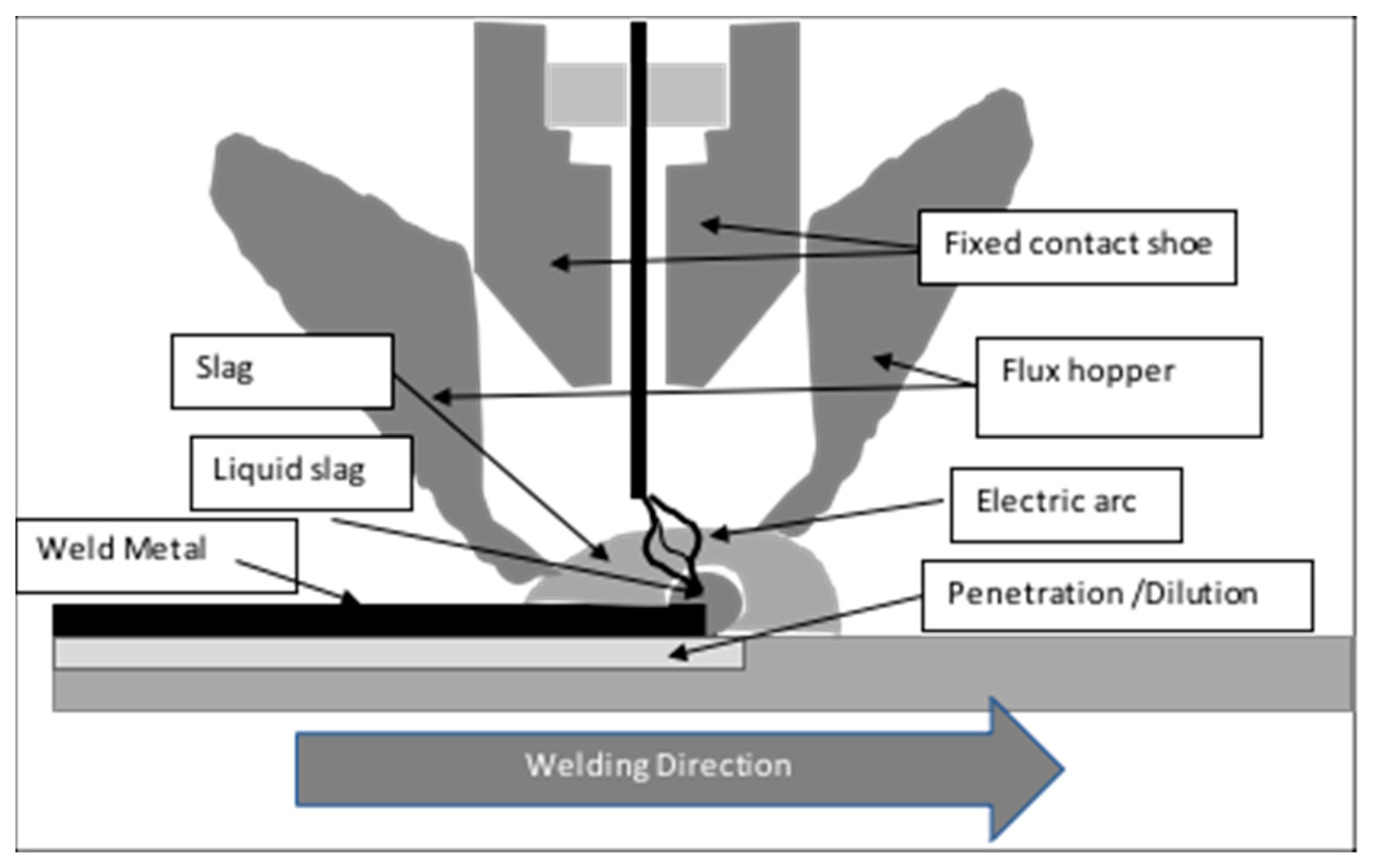
The stainless steel clad plate was manufactured by weld overlaying with the submerged-arc strip cladding method, which utilizes an arc that runs back and forth at high speeds along the strip. Two feed hoppers were necessary to guarantee the complete protection of the electrical arc. A simplified scheme of the adopted overlay welding process is shown in Figure 1. The process was conducted by means of a protective slag. Q235 steel was chosen as a substrate, and the AISI 316 strip was chosen as cladding material (strip of 30 mm wide and thickness of 0.5 mm). Q235 steel was chosen as a substrate. Q235 steel samples were received in the form of 16 mm thick plates after hot-rolling and quenching and tempering (Q and T) at an industrial scale. Such steel was chosen since it is characterized by good plasticity, toughness, weldability, and good cold-bending performance, making it widely used in construction and engineering welding structures. AISI 316L was chosen as the clad for its excellent corrosion performances. The two actual steel chemical composition are shown in Table 1.
Plates sizing 500 mm × 500 mm × 16 mm were clad by an external supplier. The welding supplier declared the plate manufacturing process parameters as weld metal dilution of 40%, 7 kg/h deposition, and a deposit efficiency of 95%. Two layers were deposited, and the main welding parameters are shown in Table 2.
2.1. Microstructure and Hardness
Longitudinal and transverse metallographic specimens taken from plates were prepared by a standard procedure. In particular, the steel-corrosion resistant alloy interface was examined by light microscopy (LM, Nikon) and scanning electron microscopy (SEM). The low-alloy steel was etched by Nital 2%, while the microstructure of the AISI 316L weld overlay revealed etching with 50% HNO3 + 50% H2O. In order to assess that the distribution was of various chemical elements (in particular Ni, Cr, Fe, and Mo) in the through-thickness direction, quantitative energy dispersive spectrometry (EDS) was performed by the scanning electron microscope field emission gun (SEM-FEG), LEO 1550 (Zeiss, Oberkochen, Germany). Hardness through-thickness profiles were measured by means of 10 kg Vickers hardness indenter (HV10) using steps of 0.3 and 0.5 mm at various locations on longitudinal sections.
2.2. Corrosion Testing
Pitting resistance was evaluated by measuring the critical-pitting temperature (CPT) by the American Society for Testing and Materials (ASTM) G-48 test. Additionally, Huey immersion tests in accordance with ASTM A262, Type C, were carried out to evaluate the intergranular corrosion resistance.
- ASTM G-48 test (method C). Coupons of size 20 mm × 30 mm × 1.5–2.5 mm thickness were taken from the AISI 316L clad layer. The carbon steel was machined and removed in order to obtain a flat surface. The other surface of the stainless steel coupons was practically left in the as-received condition, except for slight grinding and polishing. Duplicate specimens were considered. The ASTM G-48 test (method C) consisted of the determination of the CPT in a highly acidic media, e.g., ferric chloride. CPT temperature is defined as the lowest temperature at which pitting corrosion occurs. Test samples were exposed for 72 h to 6% ferric chloride solution. If no pitting corrosion was detected, the testing temperature was increased. The test performed was duplicated.
- ASTM A262 test (method C, Huey). This test consisted of a cyclic exposure to nitric acid of coupons (30 mm × 20 mm), taken from the AISI 316L clad layer, for 5 periods of 48 h each. The test performed was duplicated.
2.3. Heat Treatments
Specimens (100 mm × 20 mm) were taken from the clad plate and heat-treated at laboratory scale by means of an FM77H (chamber size 250 mm × 190 mm × 500 mm) muffle able to maintain 20 °C difference for 2 h. The effect of final heat-treatment conditions on the properties of both the welded layer and substrate were investigated by performing stress-relieving treatments on specimens taken from the clad plate. The original specimens were also fully retreated to simulate a Q and T treatment after cladding of the as-rolled plates. The heat-treated samples were examined in terms of microstructure and hardness indentation profiles. The following cases were considered (temperatures and holding times are indicated) (Table 3).
The 640–660 °C stress-relieving temperature range was chosen high enough (higher than the standard one for such class of material) to investigate its effect on the eventual hardness of peaks at the interface. Three different fully Q and T cycles (including austenitization step) were chosen to simulate the possibility of cladding the as-rolled plate before submitting it to a Q and T treatment.
2.4. Chemical Composition by X-ray Fluorescence (XRF)
In order to have a more quantitative assessment of the iron content in the cladding material, a through-thickness profile was measured by X-ray fluorescence (XRF), starting from the second pass layer and moving towards the base steel on 30 mm × 20 mm specimens. Because a flat surface was required for the analysis, a section perpendicular to the plate was prepared by grinding the first 0.5 mm layer at the external clad surface. After performing the chemical analysis, the other 0.5 mm was ground and a chemical analysis carried out again. This procedure was repeated for a total depth of 3.5 mm.
3. Results
3.1. As-Received Material
3.1.1. Light Microscopy Investigation
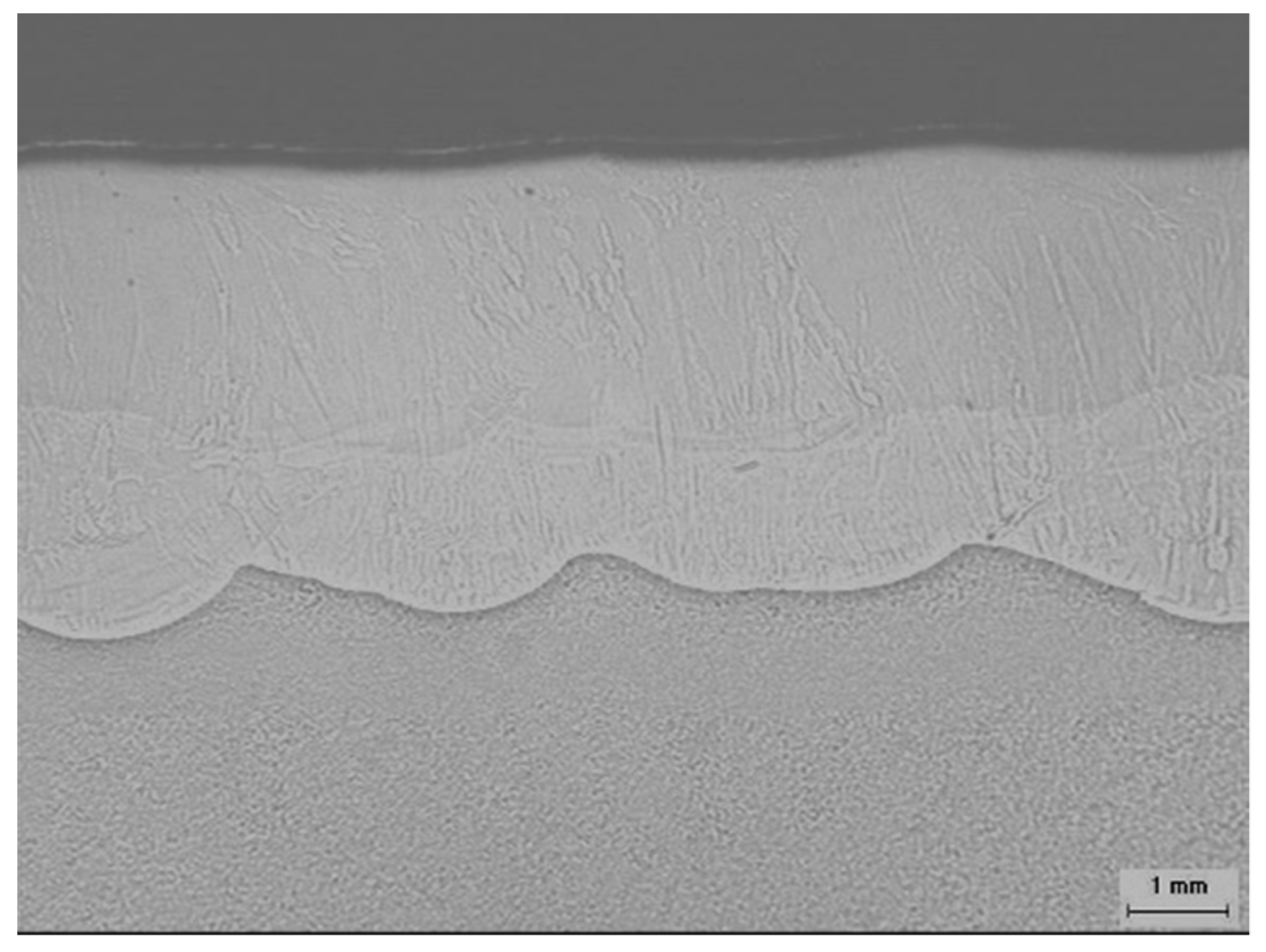
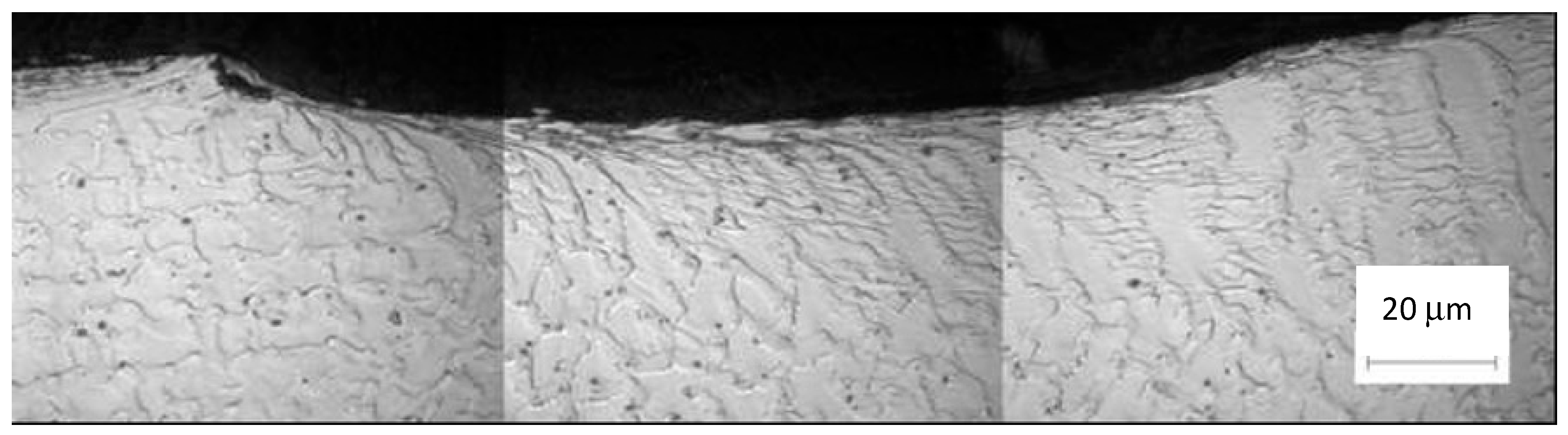
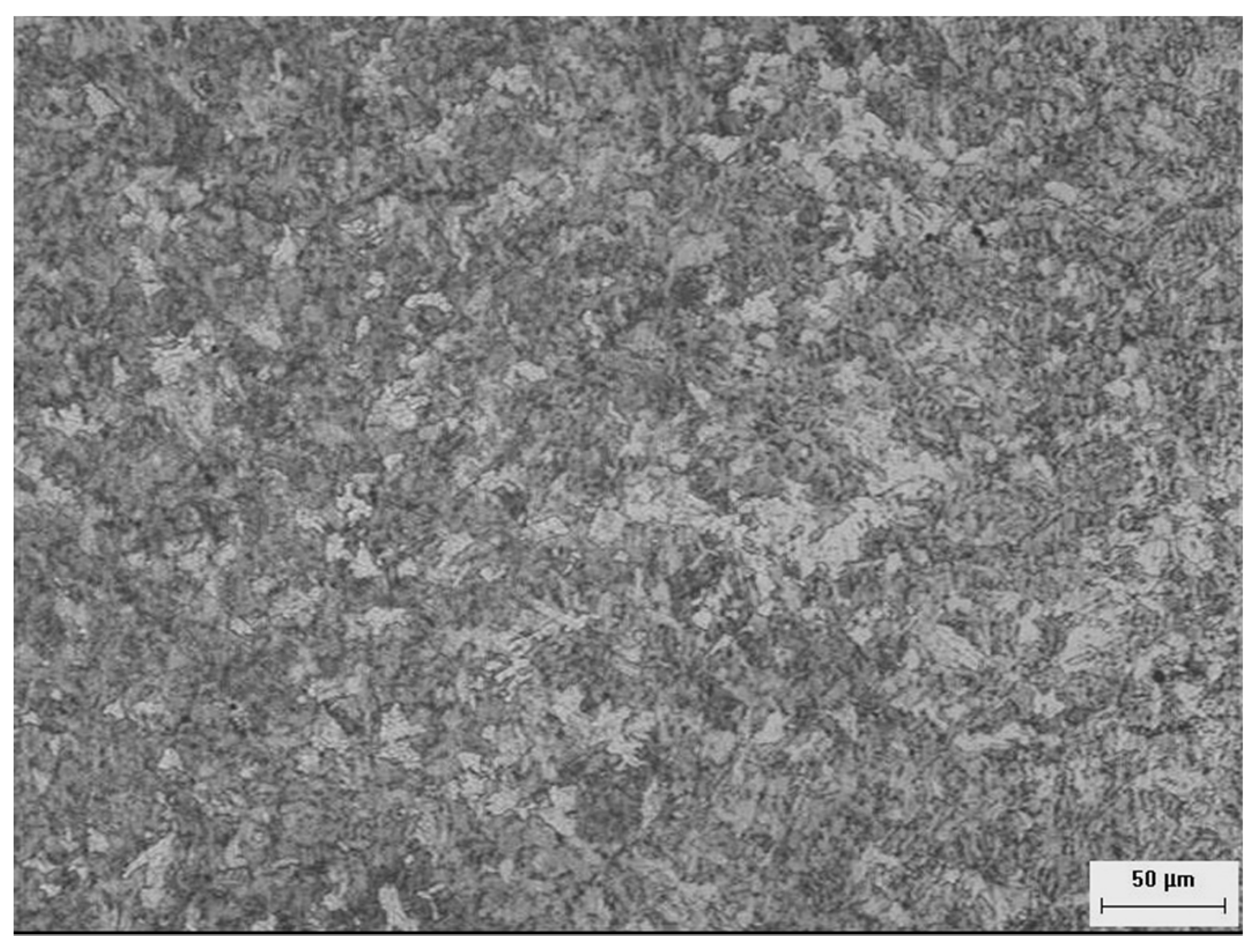
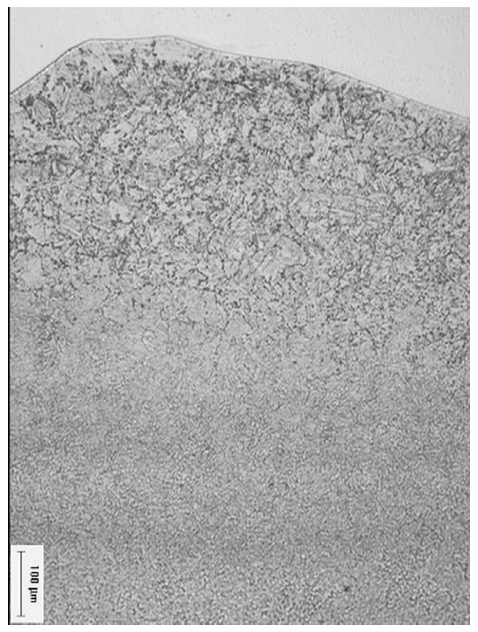
No lack of fusion or bond, cracks, or other defects are observed. The individual runs are recognized. The first weld overlay pass has a thickness of 1.2 to 2 mm, while the second pass has a thickness from 2 to 2.5 mm (Figure 2). The dendritic structure of the weld overlay (second pass) is clearly shown in Figure 3. A detail of the coarse-grained heat-affected zone (CGHAZ) is shown in Figure 4. The heat-affected zone (HAZ), 1.0 to 1.5 mm thick, can be clearly distinguished in the low-alloy steel after etching (Figure 5). Additionally, the coarse-grained heat-affected zone is revealed between adjacent runs of the first weld overlay, close to the fusion line.
3.1.2. Hardness Profiles
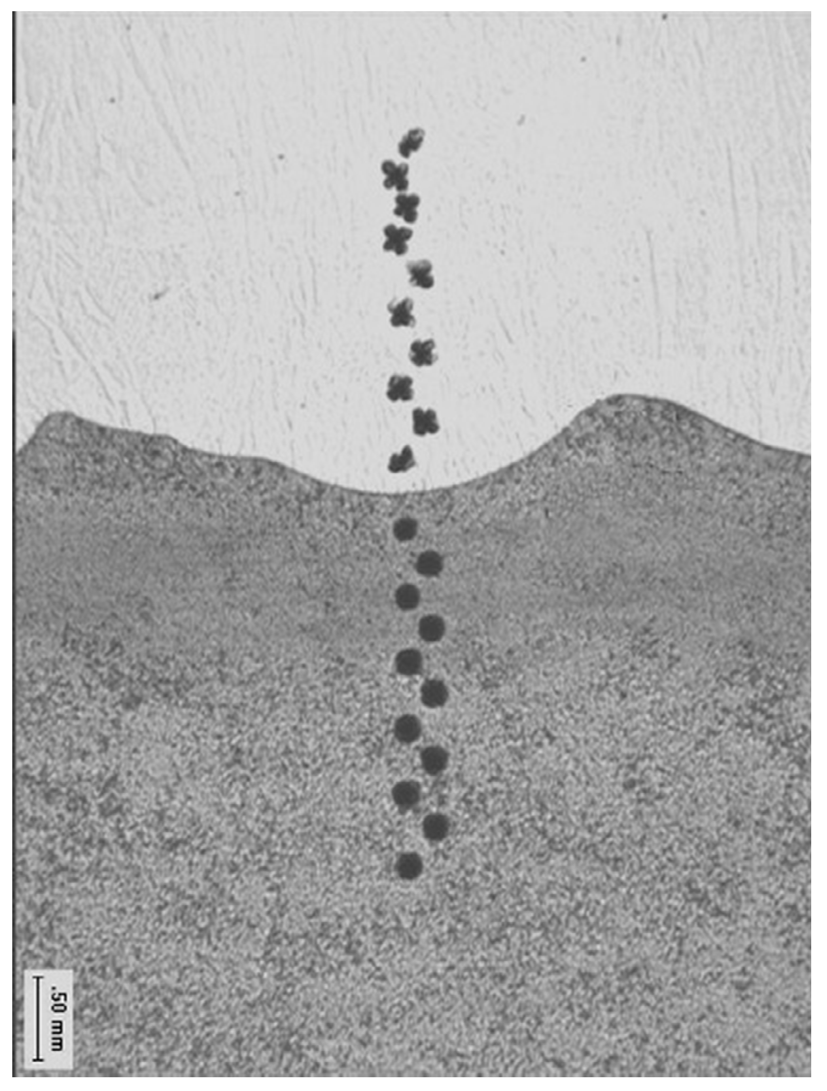
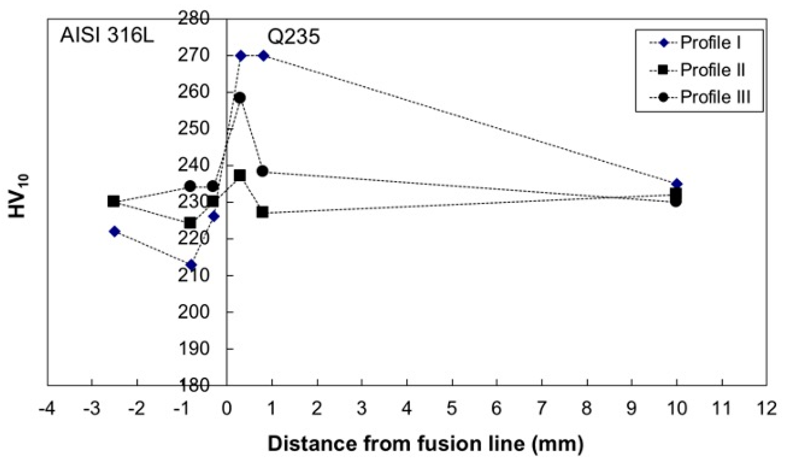
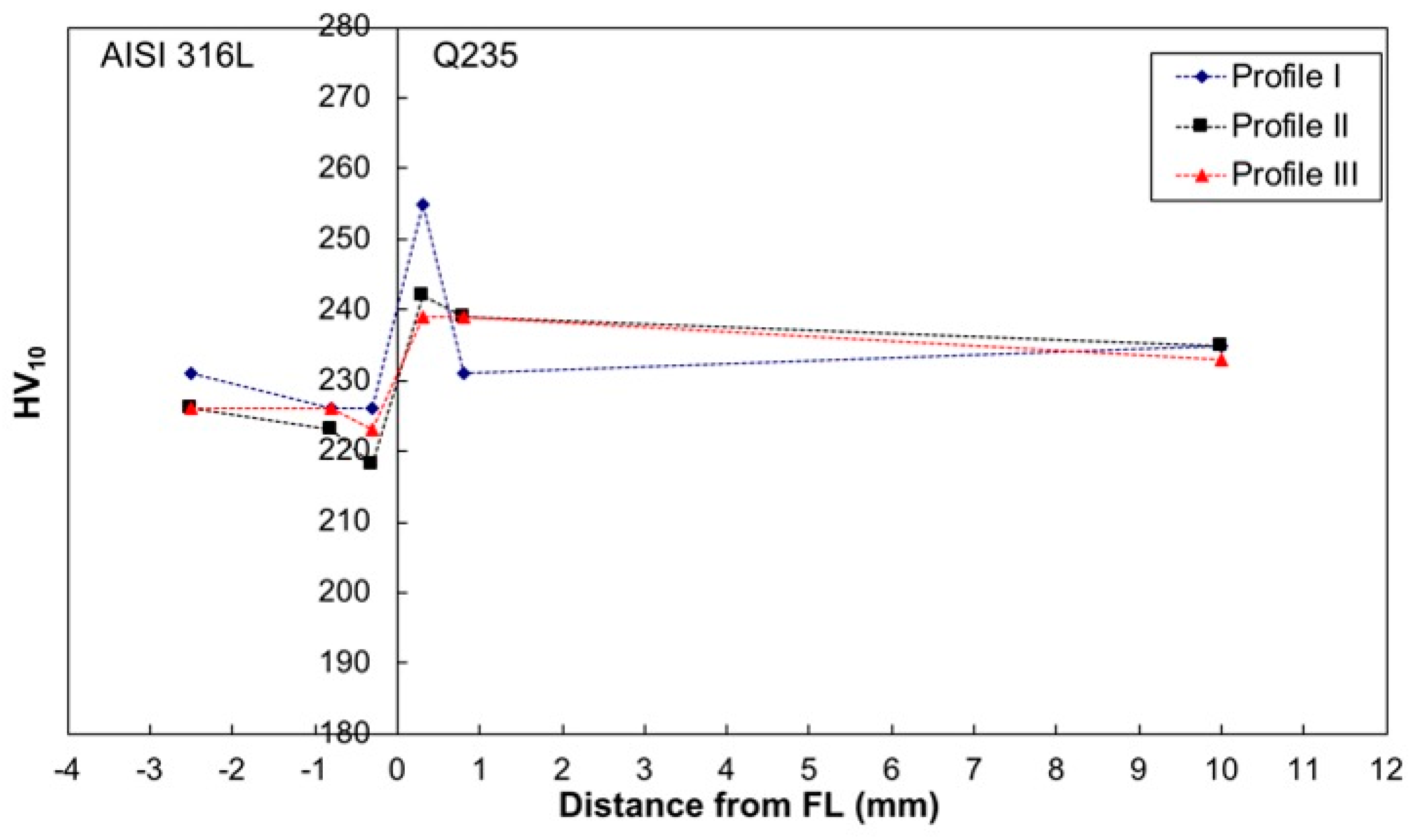
Examples of indentation array used to measure HV10 hardness are shown in Figure 6. Three indentation profiles acquired in three different positions are shown in Figure 7 (profiles 1–3). Figure 7 shows that the hardness peaks (e.g., 250 to 270 HV10) are detected in the Q235 steel close to the fusion line in the CGHAZ.
3.1.3. SEM-EDS Investigation
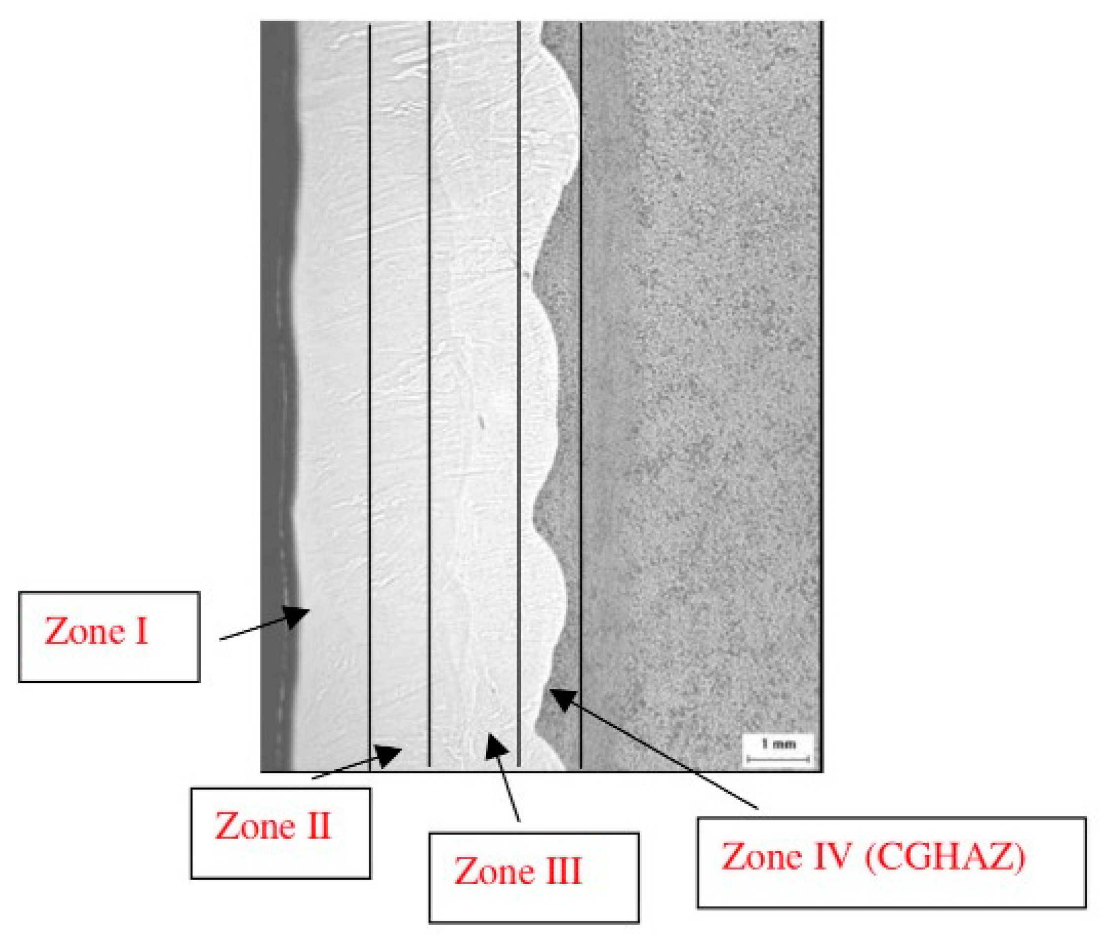
On the basis of the light microscopy results, four zones are selected (Figure 8) and examined by SEM-EDS. The average values of the EDS area analysis are shown in Table 4 for the various zones.
Zone I is chosen as the external layer zone, zone II as the interface between the two-layer passes, zone III as second layer pass, and zone IV as the carbon steel-stainless steel interface.
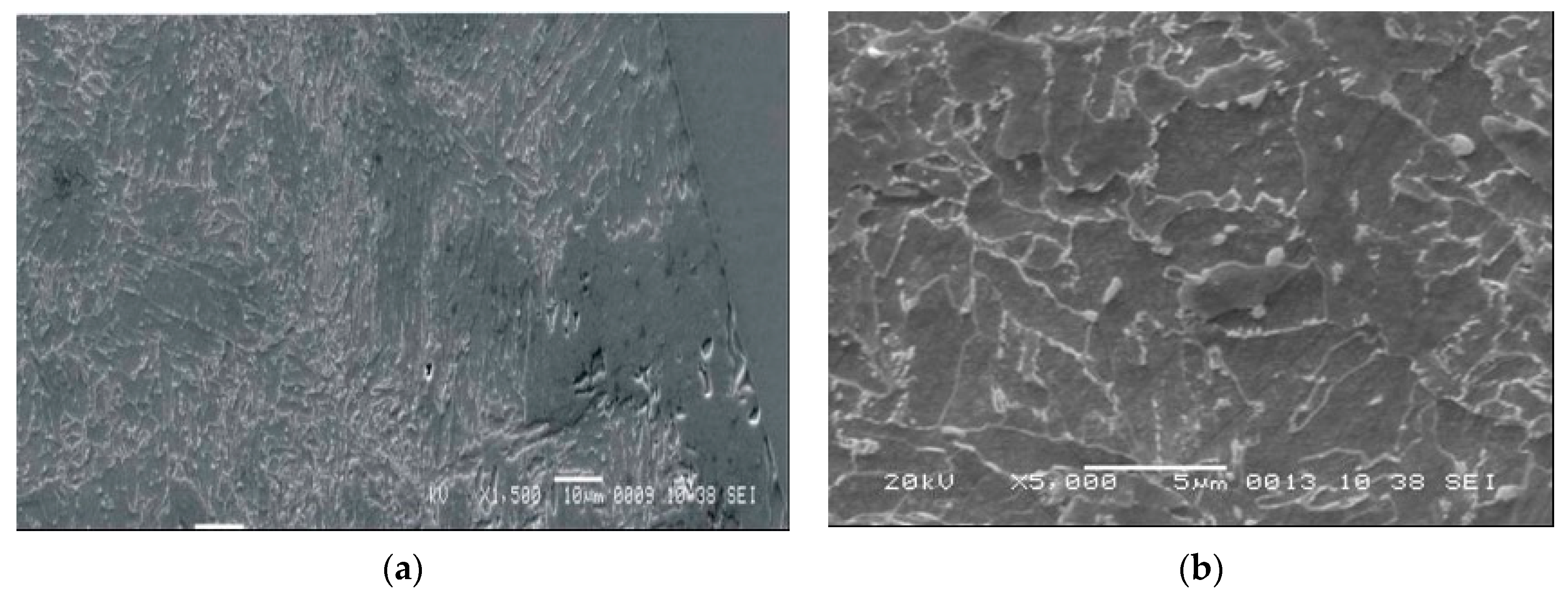
Fe increases and is detected in the weld overlay. Due to the dilution phenomena, iron is detected about 80% closer to the microalloyed steel (first pass, zone III) and about 72% closer to the second overlay pass (surface to be in contact with sour fluid, zone I), in the AISI 316L weld. In zone IV, the CGHAZ is observed (Figure 9). Austenite grains reached a size greater than 50 μm. The hardness of the peaks is attributed to increased local hardenability caused by grain-coarsening.
3.1.4. Corrosion Resistance of Clad Layer
Corrosion tests on the as-received cladding, i.e., determination of CPT by the ASTM G-48 test, were not promising (Table 5). This is because at 10 °C, severe pitting corrosion was exhibited on one face when the weld overlay specimen was machined considering all its thickness (both first and second welding pass). This behavior was likely due to excessive Fe content (>15%) in the corrosion-resistant alloy layer. Also, the Huey (ASTM A262 Type C) immersion test to evaluate the intergranular corrosion resistance gave unsatisfactory results with corrosion rates greater than 60 mm/yr in the first immersion. Later, after the third immersion, when the cladding with the lowest iron content remained, the corrosion rate decreased to 2.6 mm/year. When cladding coupons were predominantly sampled from the second overlay pass, the corrosion resistance significantly improved (Table 4) with CPT > 10 °C, and the corrosion rate in the Huey solution was about 2.5 mm/yr, although slightly below that expected for standard AISI 316L.
3.1.5. Chemical Composition Profiles
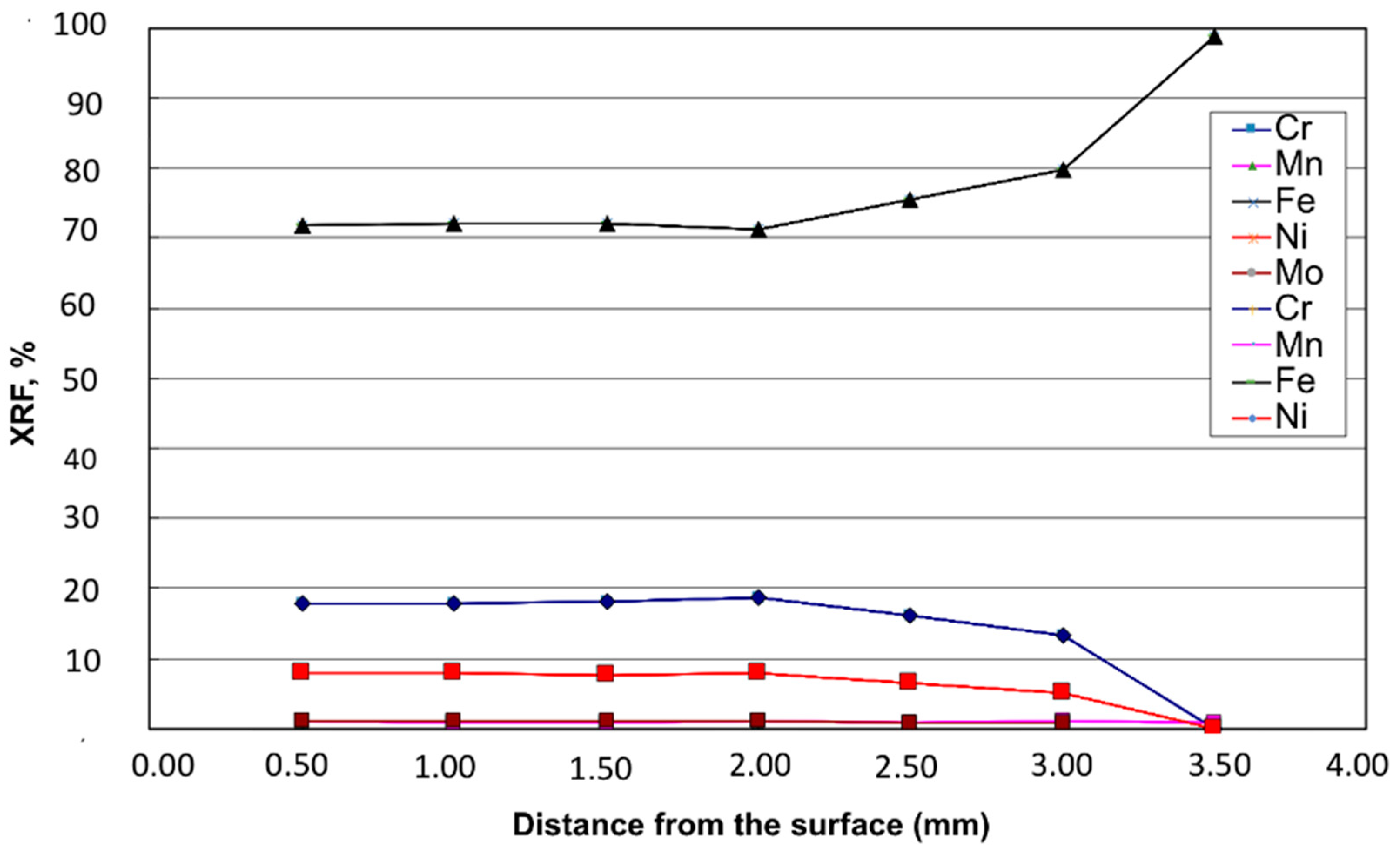
In order to have a more quantitative assessment of the iron content in the cladding, a through-thickness profile is measured by XRF on the clad material, following the procedure described in Section 2.4, for a total depth of 3.5 mm (Figure 10). The first 2 mm thick layer of the cladding shows a uniform composition of about 70%. However, depths greater than 2 mm give an iron content >70%, with values that increase almost linearly, reaching 80% at a 3.0 mm depth (Figure 9). At this position, Cr and Mo contents are about 13.1% and 0.9%, respectively. Of course, given this through-thickness profile of iron, it is very difficult to take corrosion coupons from cladding having Fe content not affected by diffusion from Q235 steel.
3.2. Stress-Relieving Effect
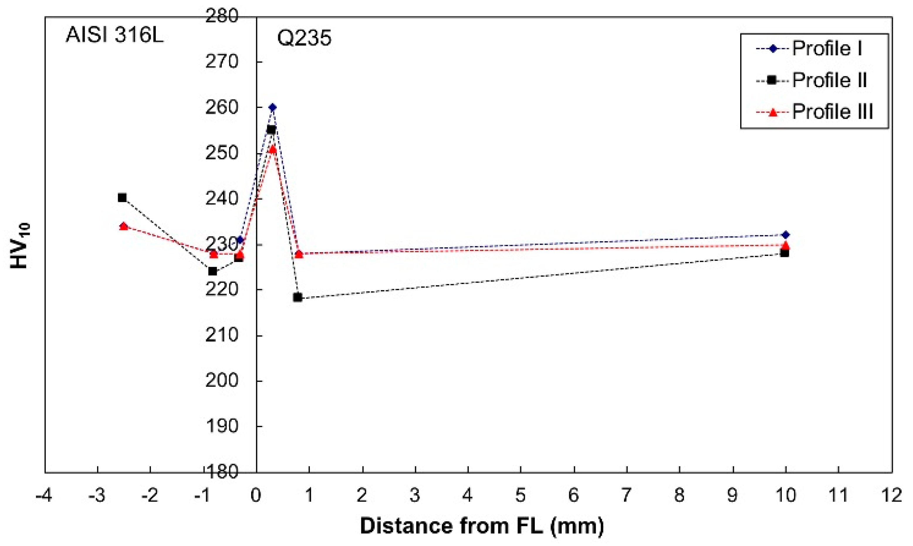
Because stress-relieving treatments do not give significant microstructural changes that can be revealed by light microscopy and SEM, only results in terms of hardness will be shown. The hardness profiles performed on the clad material after stress relieving at 640 and 660 °C for a holding time of 2 h are shown in Figure 11 and Figure 12, respectively. The hardness peaks (e.g., 255 to 260 HV10) still remain in the CGHAZ of the microalloyed steel, close to the fusion line (0.3 mm distance), although slightly reduced compared to the as-clad material.
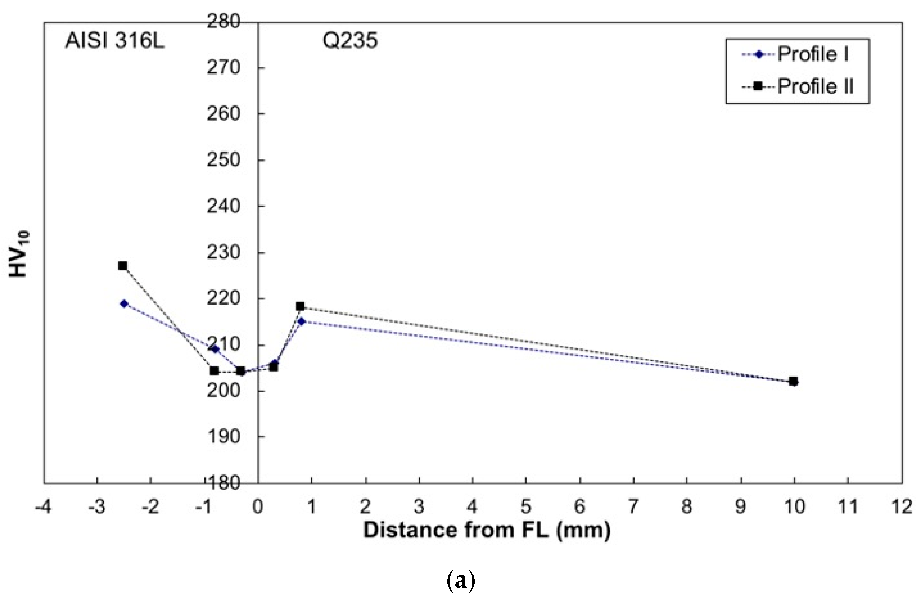
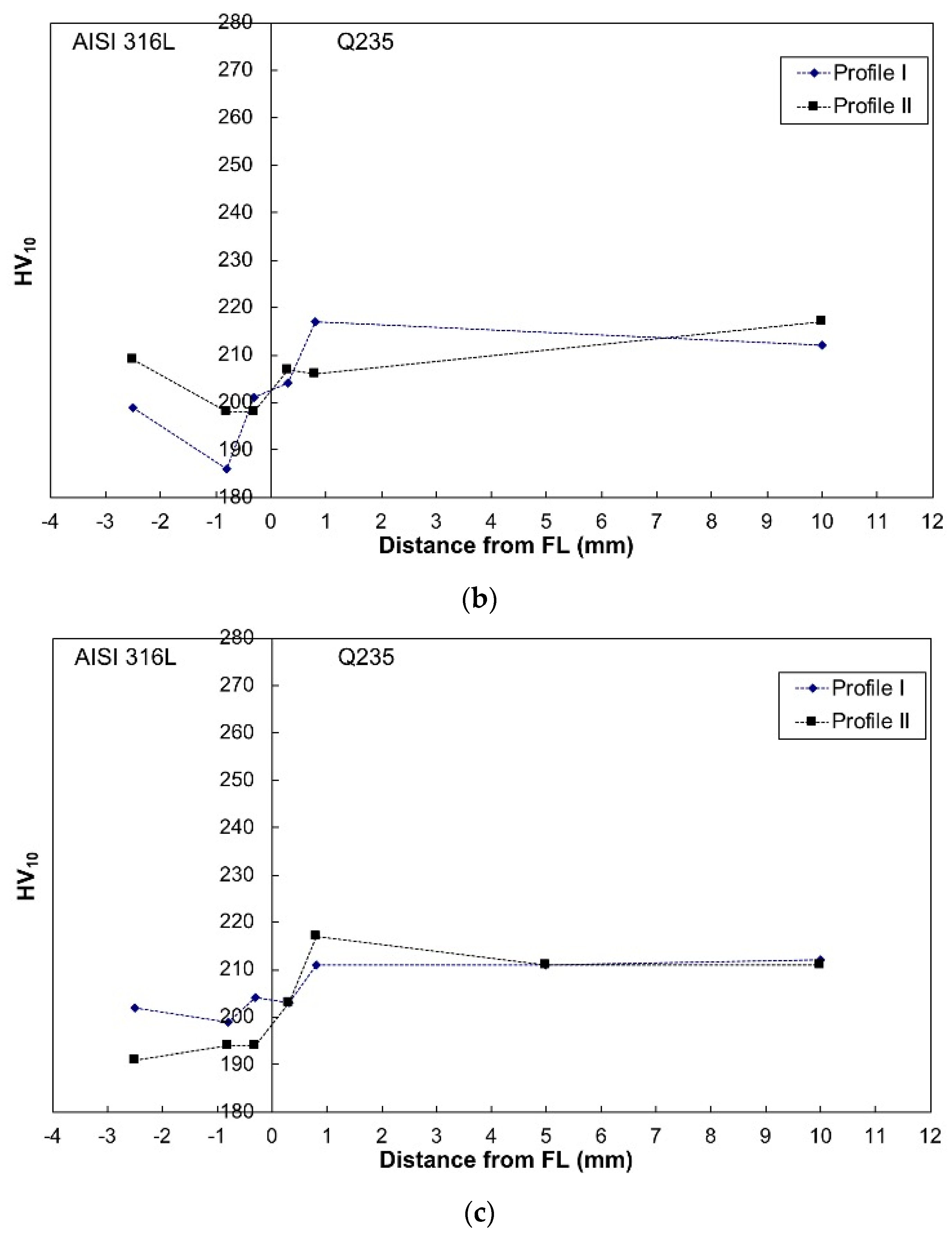
This means that stress-relieving treatments are not sufficient to avoid hardness on the higher peaks at the interface. A possible alternative in the production route is to use the as-rolled (green) plates, which are clad and submitted to Q and T treatment later. In order to investigate the possibility to follow such a route, specimens were treated considering three austenitizing temperatures, 920 °C, 980 °C, and 1000 °C, respectively, and one tempering condition (670 °C × 2 h). The lower austenitizing temperature is typical of standard (unclad) Q235 plates, while the other temperatures were selected because they were recommended for the heat treatment of AISI 316L, which is still practiced in the present industrial furnaces. The hardness profiles performed on the clad material after the Q and T laboratory treatments are shown in Figure 13.
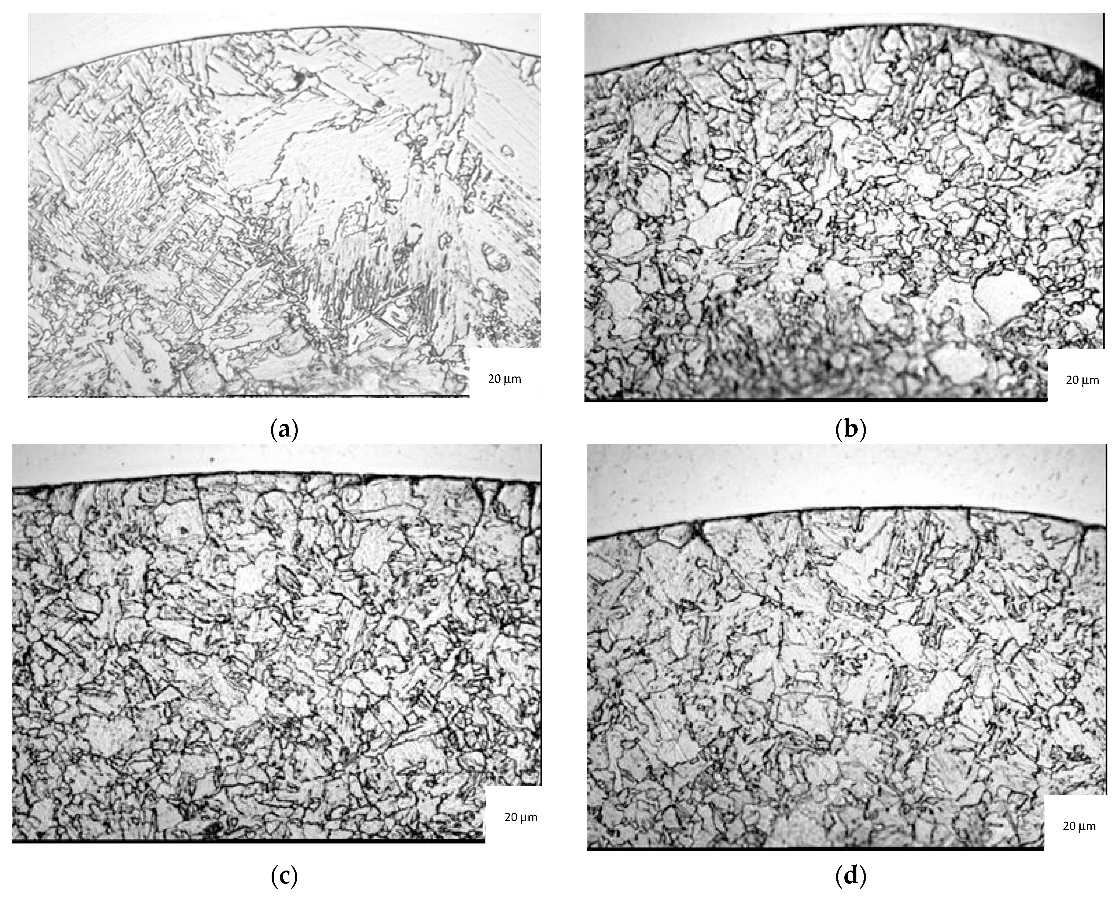
The hardness peaks in the CGHAZ of the microalloyed steel, close to the fusion line (0.3 mm distance), disappeared; they composed all values lower than 220 HV10. Reaustenitizing acts at the interface microstructure by refining austenite grain size with respect to the as-clad material (Figure 14), thus lowering local hardenability, with consequent lower hardness values at the interface. No significant effects are found depending on austenitization temperature variation in the range of 920–1000 °C. The hardness of the base material after Q and T appears slightly decreased compared to the as-clad and Q and T materials. However, this is not a critical aspect and can be balanced using a suitable tempering temperature.
4. Conclusions
The following conclusions can be drawn from the above results:
- (1)
- Corrosion tests on the clad and Q and T material, i.e., the determination of CPT by the ASTM G-48 test and Huey (ASTM A262 Type C) immersion tests to evaluate the intergranular corrosion resistance, were not promising when almost all weld overlays were sampled, likely due to excessive Fe content in the CRA layer. When cladding coupons were predominantly sampled from the second overlay pass, the corrosion resistance was significantly improved, although it remained slightly below what was expected for the standard AISI 316L steel.
- (2)
- The above results are related to the interface chemical composition. In particular, the results showed that the first 2 mm thick layer of the cladding showed a uniform composition at about 70% Fe content. However, depths greater than 2 mm gave an iron content >70%, with values that increased almost linearly, reaching 80% at 3.0 mm depth due to dilution phenomena.
- (3)
- Some hardness peaks (e.g., 250 to 270 HV10) were detected in the microalloyed steel close to the fusion line in the CGHAZ.
- (4)
- The hardness peaks in the CGHAZ of the microalloyed steel, close to the fusion line (0.3 mm distance), disappeared after Q and T; they composed all values lower than 220 HV10. This means that the reaustenitizing treatment, at temperatures below those experienced at 0.3 mm from the fusion line, produces a refinement of austenite grains, sufficient to decrease hardenability and hardness after tempering.
Author Contributions
Conceptualization, A.D.S. and C.T.; methodology, A.D.S. and C.T.; formal analysis, A.D.S. and C.T. All authors have read and agreed to the published version of the manuscript.
Funding
This research received no external funding.
Conflicts of Interest
The authors declare no conflict of interest.
References
- Lee, K.S.; Yoon, D.H.; Kim, H.K.; Kwon, Y.-N.; Lee, Y.-S. Effect of annealing on the interface microstructure and mechanical properties of a STS–Al–Mg 3-ply clad sheet. Mater. Sci. Eng. A 2012, 556, 319–330. [Google Scholar] [CrossRef]
- Liu, C.Y.; Wang, Q.; Jia, Y.Z.; Jing, R.; Zhang, B.; Ma, M.Z.; Liu, R.P. Microstructures and mechanical properties of Mg/Mg and Mg/Al/Mg laminated composites prepared via warm roll bonding. Mater. Sci. Eng. A 2012, 556, 1–8. [Google Scholar] [CrossRef]
- Hang, S.U.; Luo, X.-B.; Chai, F.; Shen, J.-C.; Sun, X.-J.; Lu, F. Manufacturing Technology and Application Trends of Titanium Clad Steel Plates. J. Iron Steel Res. Int. 2015, 22, 977–982. [Google Scholar]
- Marshall, P. Austenitic Stainless Steels: Microstructure and Mechanical Properties; Elsevier Applied Science Publisher: Amsterdam, The Netherlands, 1984. [Google Scholar]
- Di Schino, A. Manufacturing and application of stainless steels. Metals 2020, 10, 327. [Google Scholar] [CrossRef] [Green Version]
- Rufini, R.; Di Pietro, O.; Di Schino, A. Predictive simulation of plastic processing of welded stainless steel pipes. Metals 2018, 8, 519. [Google Scholar] [CrossRef] [Green Version]
- Di Schino, A.; Di Nunzio, P.E.; Turconi, G.L. Microstrucure evolution during tempering of martensite in medium carbon steel. Mat. Sci. For. 2007, 558–559, 1435–1441. [Google Scholar]
- Di Schino, A.; Kenny, J.M.; Abbruzzese, G. Analysis pf the recrystallization and grain growth processes in AISI 316 stainless steel. J. Mat. Sci. 2002, 37, 5291–5298. [Google Scholar] [CrossRef]
- Di Schino, A.; Porcu, G.; Longobardo, M.; Lopez Turconi, G.; Scoppio, L. Metallurgical design and development of C125 grade for mild sour service application. In NACE-International Corrosion Conference Series, San Diego, CA, USA, 10–14 September 2006; NACE International: Houston, TX, USA; pp. 061251–0612514.
- Di Schino, A. Analysis of heat treatment effect on microstructural features evolution in a micro-alloyed martensitic steel. Acta Met. Slovaca 2016, 22, 266–270. [Google Scholar] [CrossRef] [Green Version]
- Sharma, D.K.; Filipponi, M.; Di Schino, A.; Rossi, F.; Castaldi, J. Corrosion behaviour of high temeperature fuel cells: Issues for materials selection. Metalurgija 2019, 58, 347–351. [Google Scholar]
- Cianetti, F.; Ciotti, M.; Palmieri, M.; Zucca, G. On the evaluation of surface fatigue strength of stainless steel aeronautical component. Metals 2019, 9, 455. [Google Scholar] [CrossRef] [Green Version]
- Di Schino, A.; Valentini, L.; Kenny, J.M.; Gerbig, Y.; Ahmed, I.; Hefke, H. Wear resistance of high-nitrogen austenitic stainless steel coated with nitrogenated amorphous carbon films. Surf. Coat. Technol. 2002, 161, 224–231. [Google Scholar] [CrossRef]
- Bregliozzi, G.; Ahmed, S.I.-U.; Di Schino, A.; Kenny, J.M.; Haefke, H. Friction and wear behavior of austenitic stainless steel: Influence of atmospheric humidity, load range, and grain size. Tribol. Lett. 2004, 17, 697–704. [Google Scholar] [CrossRef]
- Valentini, L.; Di Schino, A.; Kenny, J.M.; Gerbig, Y.; Haefke, H. Influence of grain size and film composition on wear resistance of ultrafine grained AISI 304 stainless steel coated with amorphous carbon films. Wear 2002, 253, 458–464. [Google Scholar] [CrossRef]
- Zitelli, C.; Folgarait, P.; Di Schino, A. Laser powder bed fusion of stainless-steel grades: A review. Metals 2019, 9, 731. [Google Scholar] [CrossRef] [Green Version]
- Di Schino, A.; Di Nunzio, P.E. Metallurgical aspects related to contact fatigue phenomena in steels for back up rolling. Acta Met. Slovaca 2017, 23, 62–71. [Google Scholar] [CrossRef] [Green Version]
- Li, C.; Quin, G.; Tang, Y.; Zhang, B.; Lin, S.; Geng, P. Microstructures and mechanical properties of stainless steel clad plate joint with diverse filler metals. J. Mat. Res. Technol. 2020, 9, 2522–2534. [Google Scholar] [CrossRef]
- Wang, Y.; Li, X.; Wang, X.; Yan, H. Fabrication of a thick copper-stainless steel clad plate for nuclear fusion equipment by explosive welding. Fusion Eng. Des. 2018, 137, 91–96. [Google Scholar] [CrossRef]
- Qin, Q.; Zhang, D.-T.; Zang, Y.; Guan, B. A simulation study on the multi-pass rolling bond of 316L/Q345R stainless clad plate. Adv. Mech. Eng. 2015, 7, 1–13. [Google Scholar] [CrossRef] [Green Version]
- Li, Y.-W.; Liu, H.-T.; Wang, Z.-J.; Zhang, X.-M.; Wang, G.-D. Suppression of edge cracking and improvement of ductility in high borated stainless steel composite plate fabricated by hot-roll-bonding. Mater. Sci. Eng. A 2018, 731, 377–384. [Google Scholar] [CrossRef]
- Mousawi, A.; Barrett, S.A.A.; Al-Hassani, S.T.S. Explosive welding of metal plates. J. Mater. Process. Technol. 2008, 202, 224–239. [Google Scholar]
- Tian, M.J.; Chen, H.; Zhang, Y.K.; Wang, T.; Zhu, Z.Y. Welding process of composite plate for construction and its welded microstructure and properties. Heat Treat. Met. 2015, 40, 110–115. [Google Scholar]
- Qiu, T.; Wu, B.X.; Chen, Q.Y.; Chen, W.J. Analysis on welded joint properties of stainless clad steel plates. Electric Weld. Mach. 2013, 43, 83–87. [Google Scholar]
- Liao, H.M.; Song, K.Q.; Cao, Y.P.; Zeng, M. Welding process and welded joint microstructure of austenitic stainless clad steel plate. Hot Work. Technol. 2012, 41, 148–150. [Google Scholar]
- Wang, W.X.; Wang, Y.F.; Liu, M.C.; Cheng, F.C.; Wu, W. Microstructure and corrosion resistance of butt joint of 1Cr18Ni9Ti+Q235 composite plate. Trans. China Weld. Inst. 2010, 31, 89–92. [Google Scholar]
- Zhang, J.J.; Ju, Z.P. Investigation on welding performance of 321–Q345q–D composite steel plate used in railway bridge. Steel Constr. 2012, 27, 48–53. [Google Scholar]
- Napoli, G.; Di Schino, A.; Paura, M.; Vela, T. Colouring titanium alloys by anodic oxidation. Metalurgija 2018, 57, 111–113. [Google Scholar]
- Xin, J.; Song, Y.; Fang, J.; Wei, J.; Huang, C.; Wang, S. Evaluation of inter-granular corrosion susceptibility in 304LN austenitic stainless steel weldments. Fusion Eng. Des. 2018, 133, 70–76. [Google Scholar] [CrossRef]
- Aydogdu, G.H.; Aydinol, M.K. Determination of susceptibility to intergranular corrosion and electrochemical reactivation behaviour of AISI 304L type stainless steel. Corros. Sci. 2006, 8, 3565–3583. [Google Scholar] [CrossRef]
- Li, H.; Zhang, L.; Zhang, B.; Zhang, Q. Microstructure characterization and mechanical properties of stainless steel clad plate. Materials 2019, 12, 509. [Google Scholar] [CrossRef] [Green Version]
- Li, Z.; Wang, X.; Luo, Y. Equivalent properties of transition layer based on element distribution in laser bending of 304 stainless steel/Q235 carbon steel laminated plate. Materials 2018, 11, 2326. [Google Scholar] [CrossRef] [Green Version]
- Jing, Y.-A.; Qin, Y.; Zang, X.; Shang, Q.; Song, H. A novel reduction-bonding process to fabricate stainless steel clad plate. J. Alloys Compd. 2014, 617, 688–698. [Google Scholar] [CrossRef]
- Liu, B.X.; Wei, J.Y.; Yang, M.X.; Yin, F.X.; Xu, K.C. Effect of heat treatment on the mechanical properties of copper clad steel plates. Vacuum 2018, 154, 250–258. [Google Scholar] [CrossRef]
- Dhib, Z.; Guermazi, N.; Ktari, A.; Gasperini, M.; Haddar, N. Mechanical bonding properties and interfacial morphologies of austenitic stainless steel clad plates. Mater. Sci. Eng. A 2017, 696, 374–386. [Google Scholar] [CrossRef]
- Yu, T.; Jing, Y.-A.; Yan, X.; Li, W.; Pang, Q.; Jing, G. Microstructures and properties of roll-bonded stainless/medium carbon steel clad plates. J. Mater. Process. Technol. 2019, 266, 264–273. [Google Scholar]
- Chen, C.X.; Liu, M.Y.; Liu, B.X.; Yin, F.X.; Dong, Y.C.; Zhang, X.; Zhang, F.Y.; Zhang, Y.G. Tensile shear sample design and interfacial shear strength of stainless steel clad plate. Fusion Eng. Des. 2017, 125, 431–441. [Google Scholar] [CrossRef]
- Gabrel, J.; Coussement, C.; Verelest, L.; Blum, R.; Chen, Q.; Testani, C. Superheaters materials testing for USC Boilers: Steam side oxidation rate of 9 advanced materials in industrial conditions. Mat. Sci. For. 2001, 369, 931–938. [Google Scholar] [CrossRef]
- Zhang, S.; Xiao, H.; Xie, H.; Gu, L. The preparation and property research of the stainless steel/iron scrap clad plate. J. Mater. Process. Technol. 2014, 214, 1205–1210. [Google Scholar] [CrossRef]
- Di Schino, A.; Alleva, L.; Guagnelli, M. Microstructure evolution during quenching and tempering of martensite in a medium C steel. Mat. Sci. For. 2012, 715–716, 860–865. [Google Scholar] [CrossRef]
- Song, H.; Shin, H.; Shin, Y. Heat-treatment of clad steel plate for application of hull structure. Ocean Eng. 2016, 122, 278–287. [Google Scholar] [CrossRef]
Figure 1.
Schematic view of the adopted overlay process.

Figure 2.
As-clad material (polished section).

Figure 3.
AISI 316L weld overlay (etching: 50% HNO3, and 50% H2O).

Figure 4.
Q235 substrate (Q and T material).

Figure 5.
Detail of in the coarse-grained heat-affected zone (CGHAZ) (2% Nital etching).

Figure 6.
Examples of indentation across the Q235 and AISI 316L interface.

Figure 7.
Hardness profiles across the Q235-AISI 316L interface.

Figure 8.
Identification at the light microscope of the zones examined by SEM-EDS.

Figure 9.
Detail of the CGHAZ at the Q235-AISI 316L interface.

Figure 10.
Chemical composition profiles (mass pct) through the thickness of the AISI 316L overlay by X-ray fluorescence (XRF) measurements.
Figure 10.
Chemical composition profiles (mass pct) through the thickness of the AISI 316L overlay by X-ray fluorescence (XRF) measurements.

Figure 11.
Hardness profiles across the Q235-AISI 316L interface after a stress-relieving heat treatment at 640 °C for a 2 h holding time.
Figure 11.
Hardness profiles across the Q235-AISI 316L interface after a stress-relieving heat treatment at 640 °C for a 2 h holding time.

Figure 12.
Hardness profiles across the Q235-AISI 316L interface after a stress-relieving heat treatment at 660 °C for a 2 h holding time.
Figure 12.
Hardness profiles across the Q235-AISI 316L interface after a stress-relieving heat treatment at 660 °C for a 2 h holding time.

Figure 13.
Hardness profiles across the Q235-AISI 316L interface after stress--relieving heat treatment at 920 °C × 1 h + 670 °C × 2 h (a), 980 °C × 1 h + 670 °C × 2 h and (b) 1000 °C × 1 h + 670 °C × 2 h (c).
Figure 13.
Hardness profiles across the Q235-AISI 316L interface after stress--relieving heat treatment at 920 °C × 1 h + 670 °C × 2 h (a), 980 °C × 1 h + 670 °C × 2 h and (b) 1000 °C × 1 h + 670 °C × 2 h (c).


Figure 14.
Q and T effect on the microstructure at the interface. (a) As-received material, (b) 920 °C × 1 h + 670 °C × 2 h, (c) 980 °C × 1 h + 670 °C × 2 h, and (d) 1000 °C × 1 h + 670 °C × 2 h.
Figure 14.
Q and T effect on the microstructure at the interface. (a) As-received material, (b) 920 °C × 1 h + 670 °C × 2 h, (c) 980 °C × 1 h + 670 °C × 2 h, and (d) 1000 °C × 1 h + 670 °C × 2 h.


Table 1.
Main chemical composition of the considered materials (mass, %).
| Alloy | Cr | Ni | Mo | Mn | C | Si | P | S | Fe |
|---|---|---|---|---|---|---|---|---|---|
| AISI 316 L | 17.9 | 8.0 | 1.1 | 1.5 | 0.02 | 0.12 | 0.020 | 0.10 | Balance |
| Q235 | 0 | 0 | 0 | 1.0 | 0.20 | 0.35 | 0.040 | 0.40 | Balance |
Table 2.
Adopted main welding parameters.
| Welding Parameters | Values |
|---|---|
| Welding Current | 450–550 A |
| Arc Voltage | 28–33 V |
| Travel Speed | 2–3 mm/s |
| Stick-out | 35 mm |
| Overlap | 8–11 mm |
| Heat Input Max | 5.3 (kJ/mm) |
| Preheat temperature | About 150 °C |
Table 3.
Heat treatment conditions on the performed tests.
| Material State | Performed Tests | |
|---|---|---|
| Hardness | Microstructure | |
| Q&T+ cladding | √ | √ |
| Stress relieved at 640 °C × 2 h | √ | |
| Stress relieved at 660 °C × 2 h | √ | √ |
| Q&T (920 °C × 1 h + 670 °C × 2 h) | √ | √ |
| Q&T (980 °C × 1 h + 670 °C × 2 h) | √ | √ |
| Q&T (1000 °C × 1 h + 670 °C × 2 h) | √ | √ |
Table 4.
Quantitative SEM-EDS microanalysis (mass, %).
| Cr % | Ni % | Mn % | Mo % | Fe, % | |
|---|---|---|---|---|---|
| Zone IV (CGHAZ) | 0.05 | 0.1 | 0.9 | 0.05 | 98.9 |
| Zone III | 13.2 | 5.0 | 1.0 | 0.50 | 80.3 |
| Zone II | 18.8 | 7.7 | 0.9 | 1.1 | 71.5 |
| Zone I | 17.9 | 7.8 | 1.0 | 1.2 | 72.1 |
Table 5.
The corrosion resistance of the clad layer.
| Cladding Specimens | CPT (°C) ASTM G-48 | Corrosion Rate (mm/year) ASTM A262-C |
|---|---|---|
| 2.5 mm thickness (almost total weld overlay) | Failed at 20 °C (heavy corrosion) | 61 mm/year (first cycle) 2.6 mm/year (third cycle) |
| 1.5 mm thickness (second pass of the weld overlay) | Failed at 20 °C (5 pits) | 2.4 mm/year (first cycle) 2.4 mm/year (third cycle) |
| 1.5 mm thickness (second pass of the weld overlay) | Passed at 10 °C | - |
© 2020 by the authors. Licensee MDPI, Basel, Switzerland. This article is an open access article distributed under the terms and conditions of the Creative Commons Attribution (CC BY) license (http://creativecommons.org/licenses/by/4.0/).
Share and Cite
MDPI and ACS Style
Di Schino, A.; Testani, C. Corrosion Behavior and Mechanical Properties of AISI 316 Stainless Steel Clad Q235 Plate. Metals 2020, 10, 552. https://0-doi-org.brum.beds.ac.uk/10.3390/met10040552
AMA Style
Di Schino A, Testani C. Corrosion Behavior and Mechanical Properties of AISI 316 Stainless Steel Clad Q235 Plate. Metals. 2020; 10(4):552. https://0-doi-org.brum.beds.ac.uk/10.3390/met10040552
Chicago/Turabian StyleDi Schino, Andrea, and Claudio Testani. 2020. "Corrosion Behavior and Mechanical Properties of AISI 316 Stainless Steel Clad Q235 Plate" Metals 10, no. 4: 552. https://0-doi-org.brum.beds.ac.uk/10.3390/met10040552
Note that from the first issue of 2016, this journal uses article numbers instead of page numbers. See further details here.