Study on Solidification Structure Evolution of Direct-Chill Casting High Purity Copper Billet Using Cellular Automaton-Finite Element Method

 , ,
, ,
Abstract
:1. Introduction
2. Model and Method Descriptions
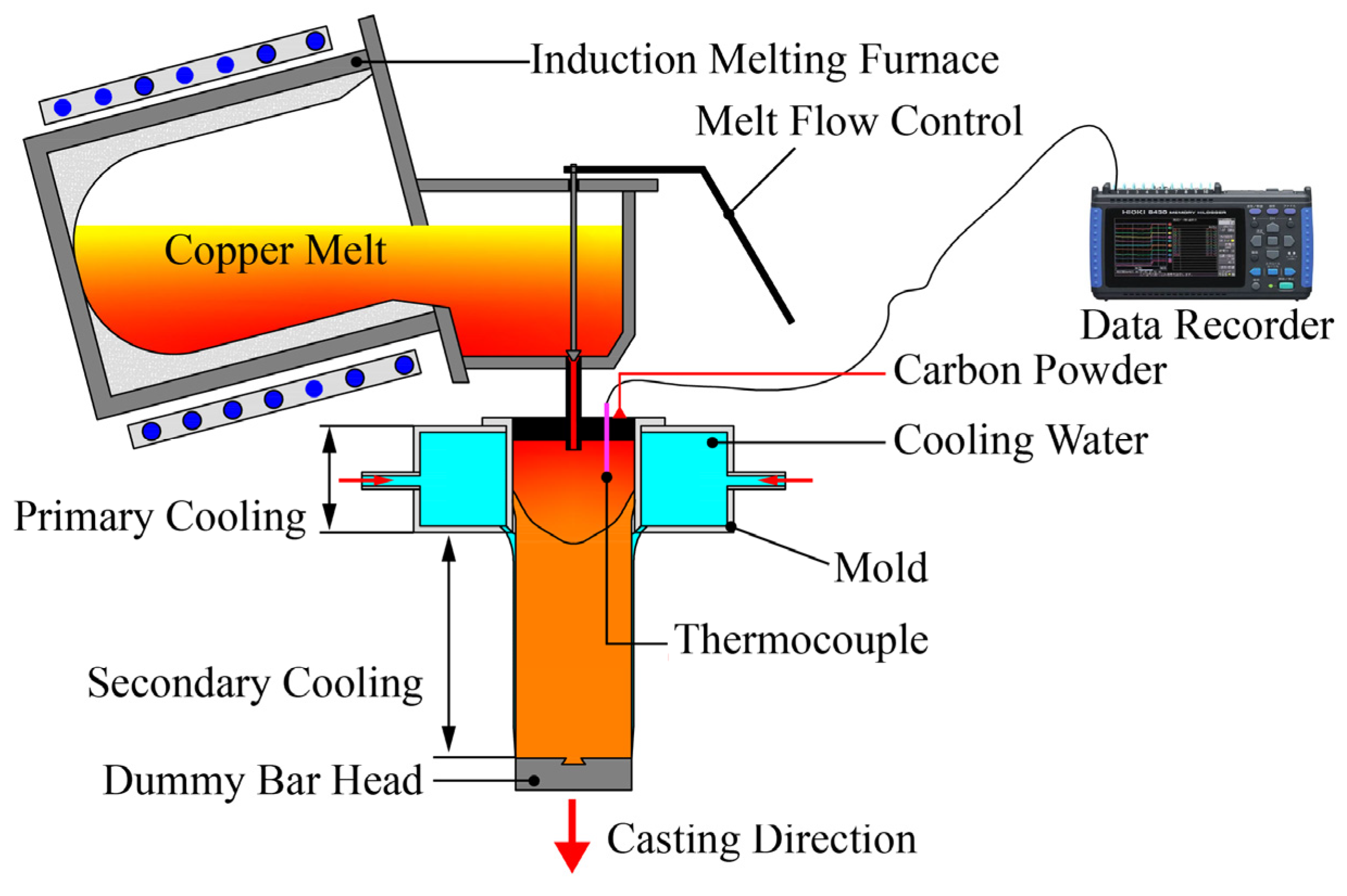
2.1. Experimental Material and Methods
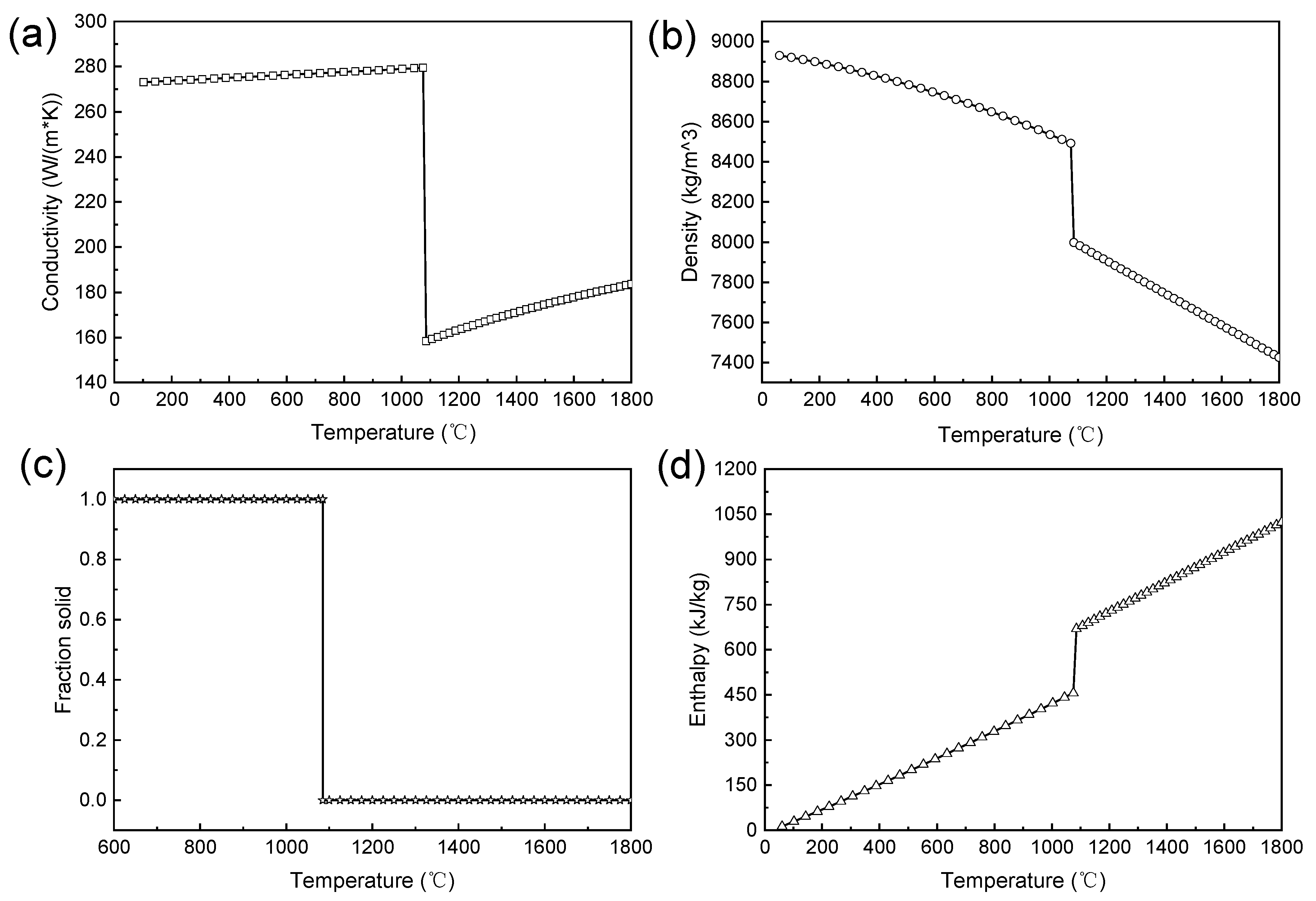
2.2. Heat Transfer Model
2.2.1. Governing Equations
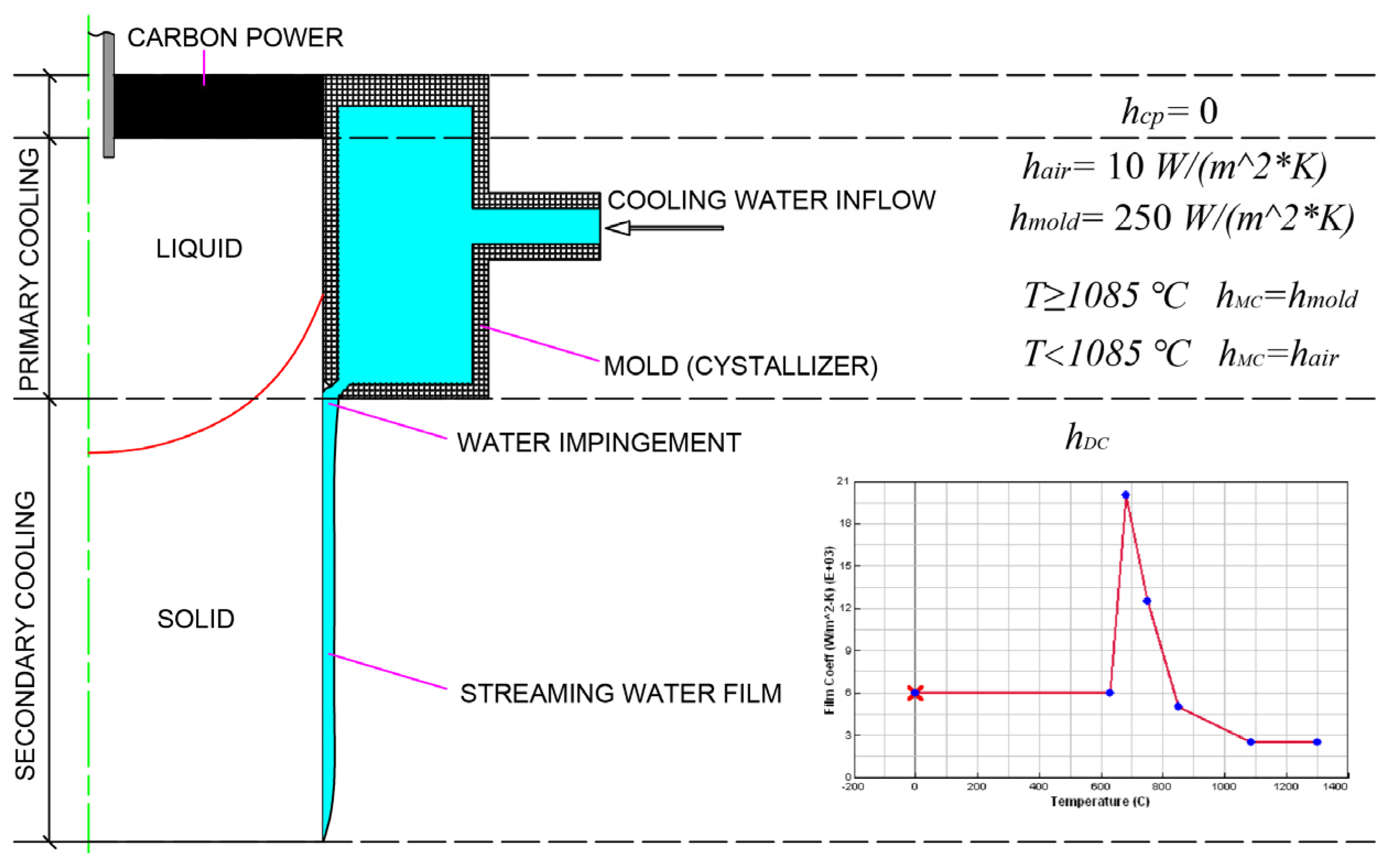
2.2.2. Boundary Conditions
2.3. CAFE Model
2.3.1. Nucleation Model
2.3.2. Growth Kinetics Model
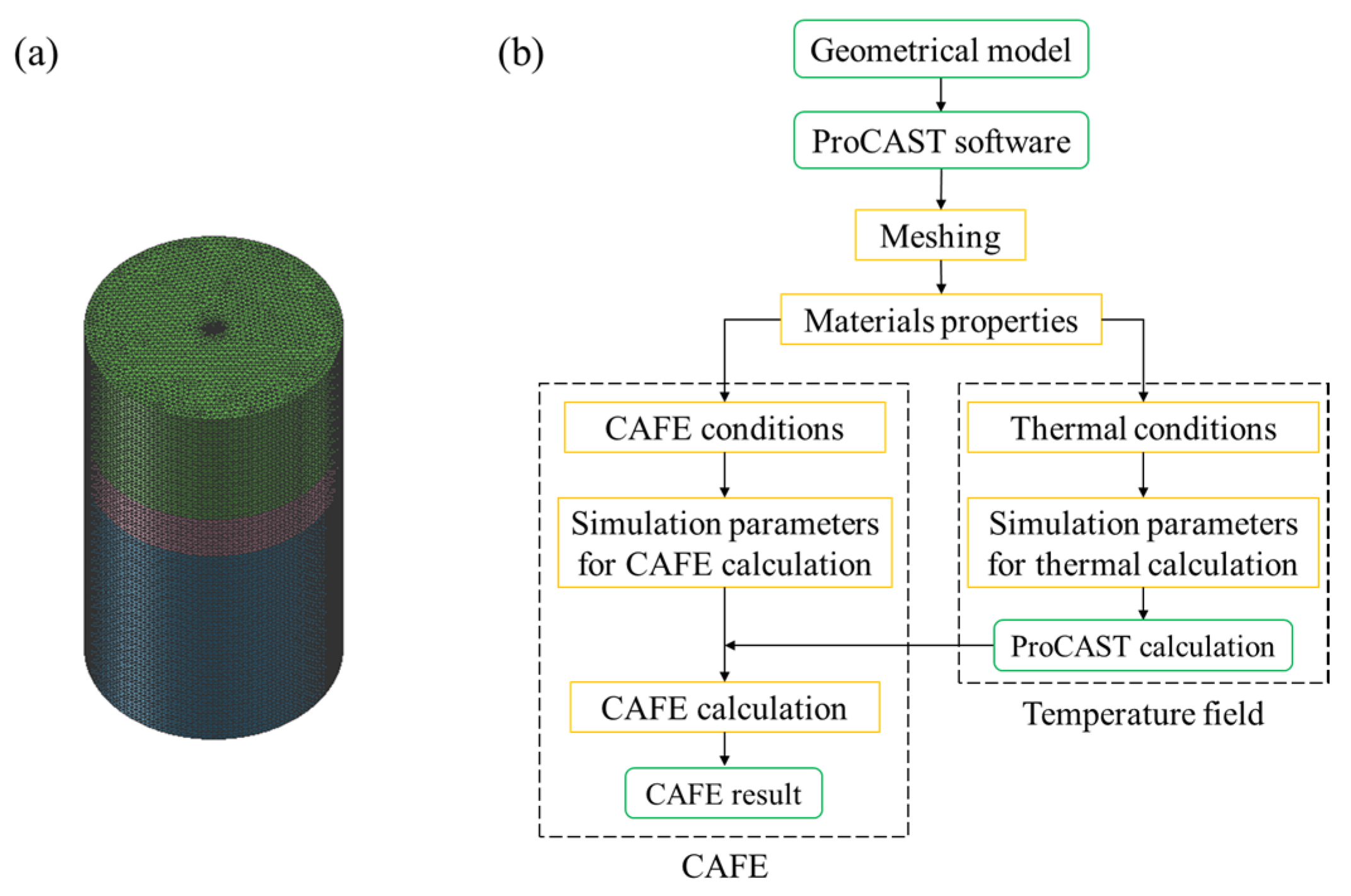
2.3.3. Calculation Procedures
3. Model Validation
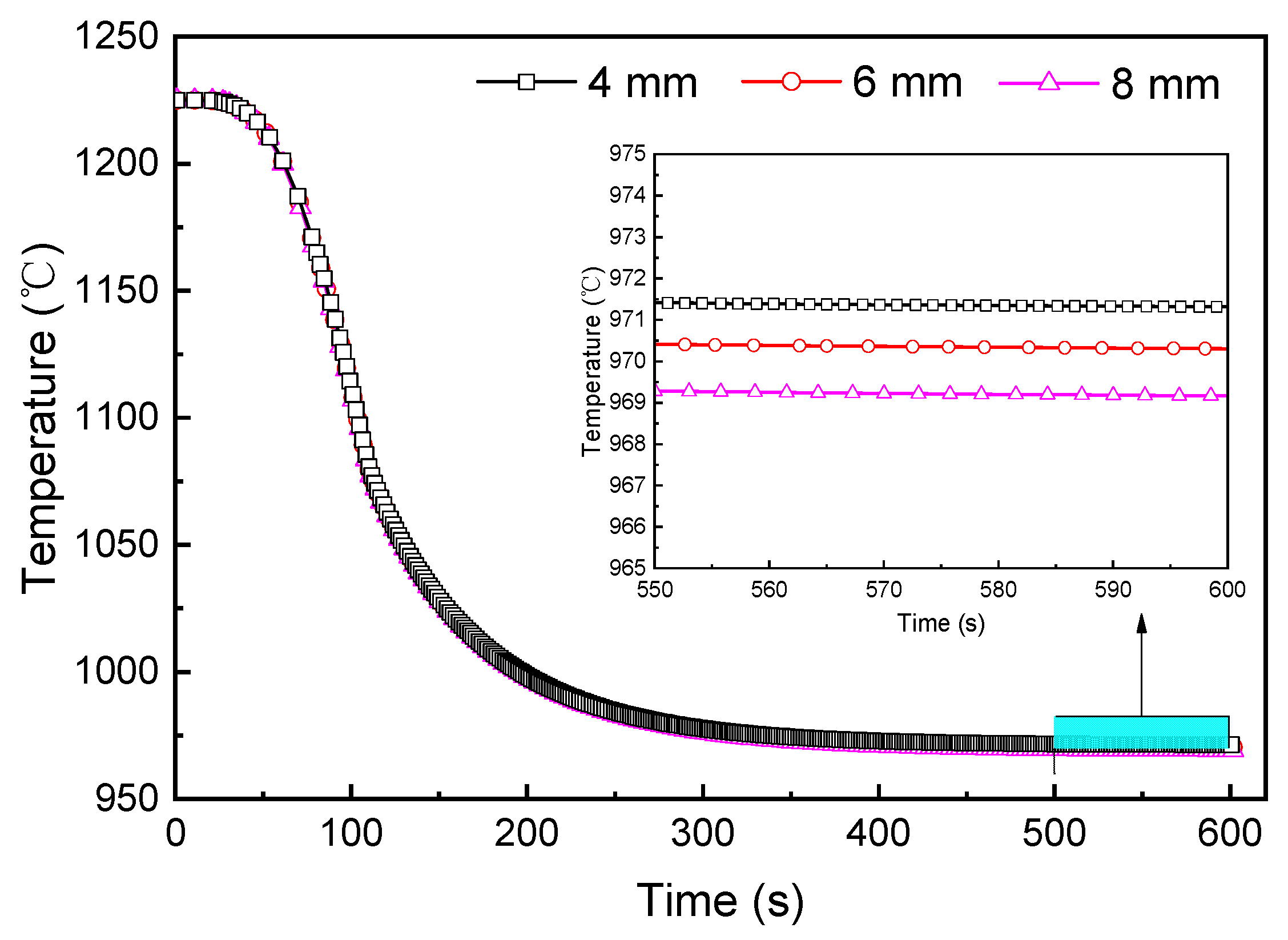
3.1. Mesh Size
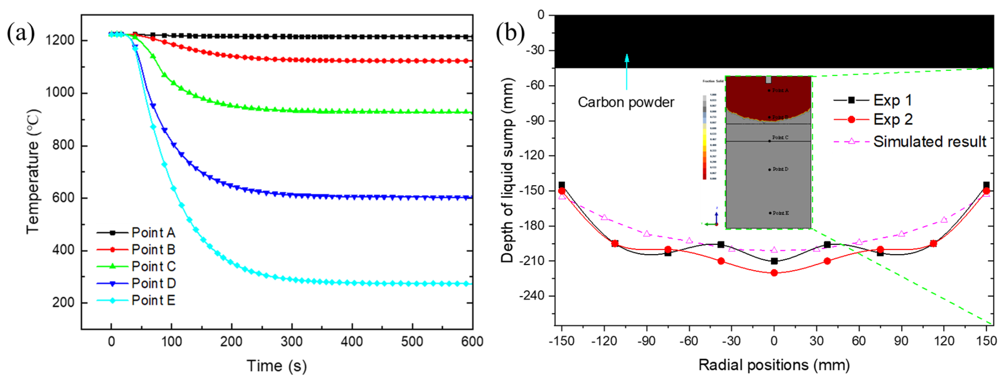
3.2. Comparison of Simulation and Experimental Results
4. Results and Discussion
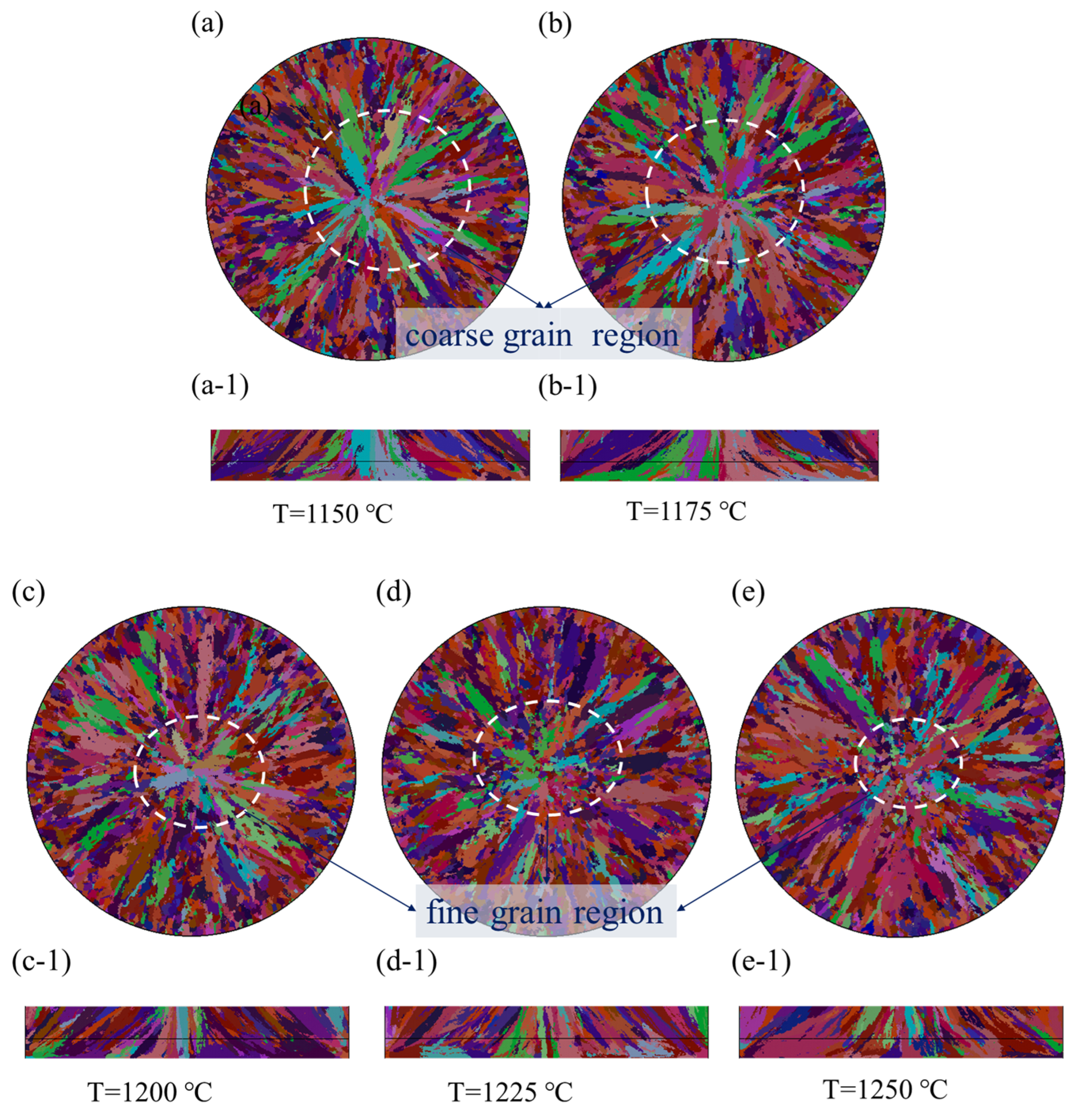
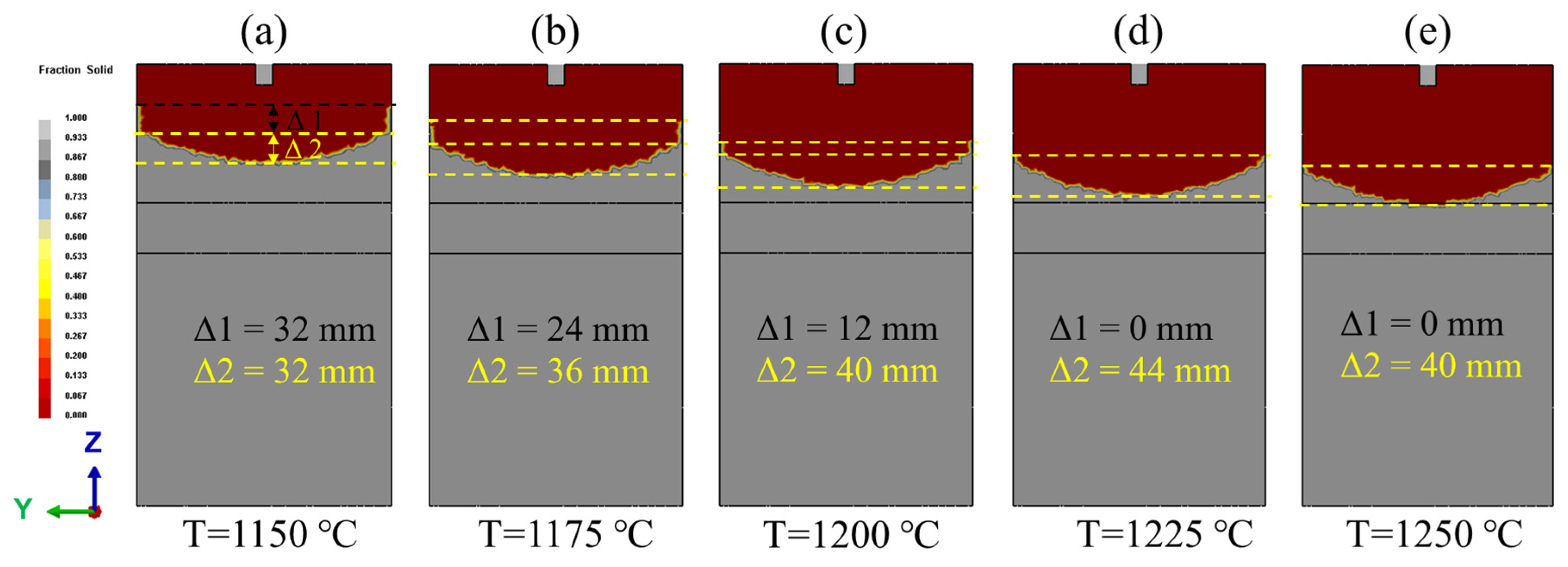
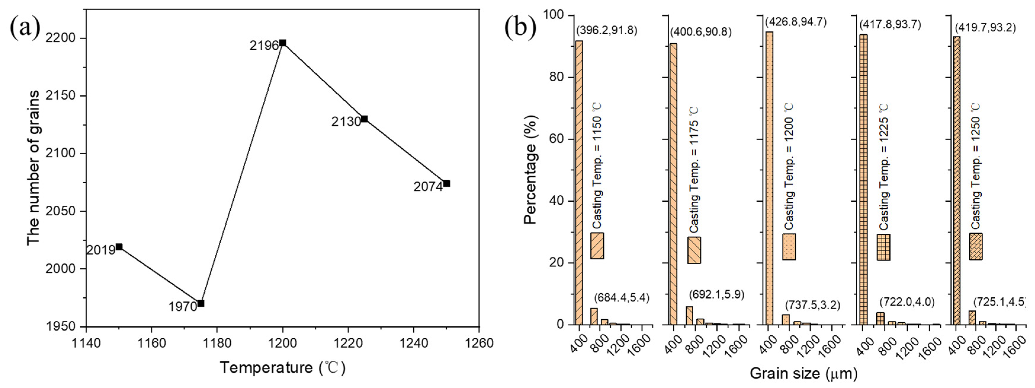
4.1. The Effect of Casting Temperature on Solidification Structure Evolution
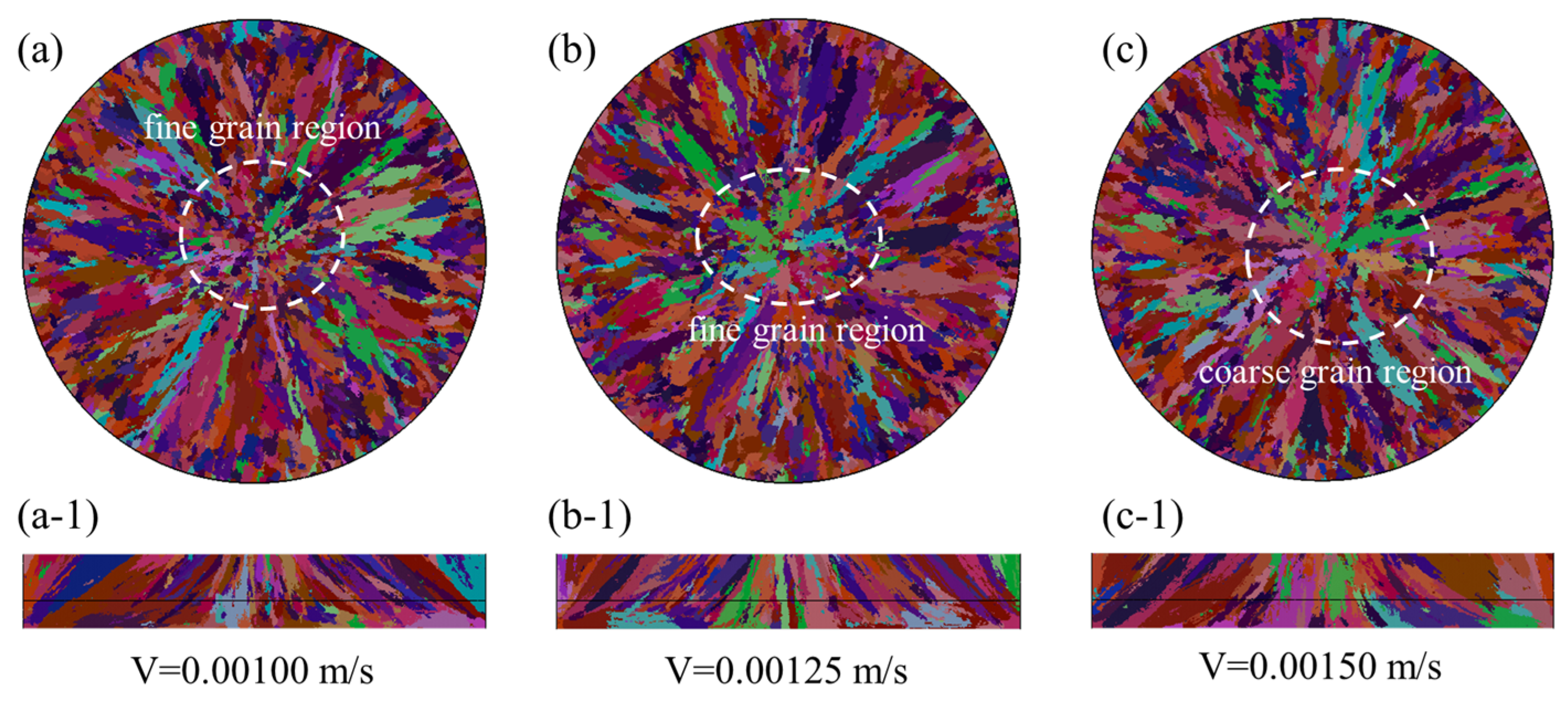
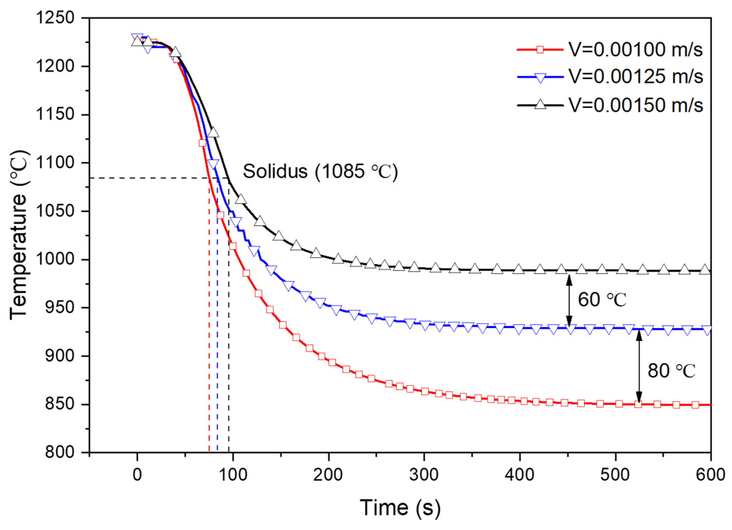
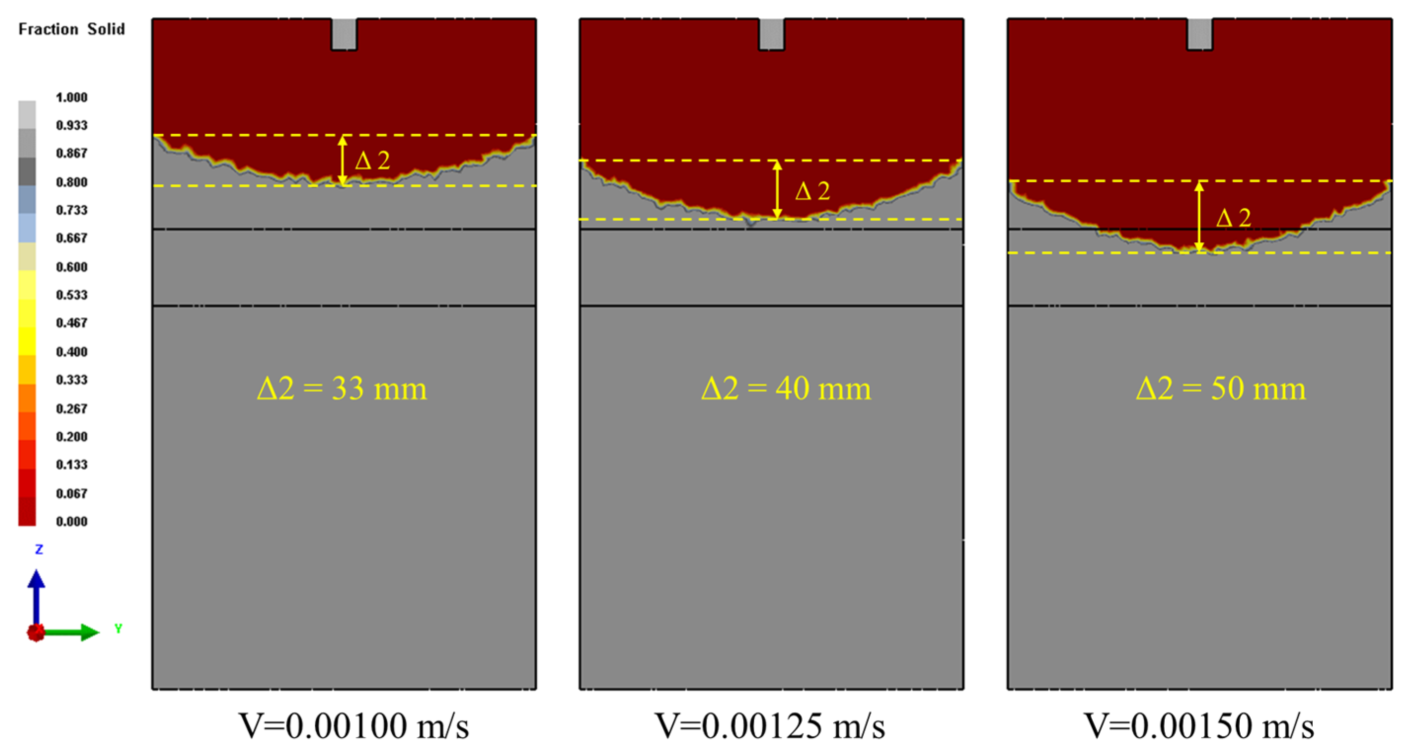
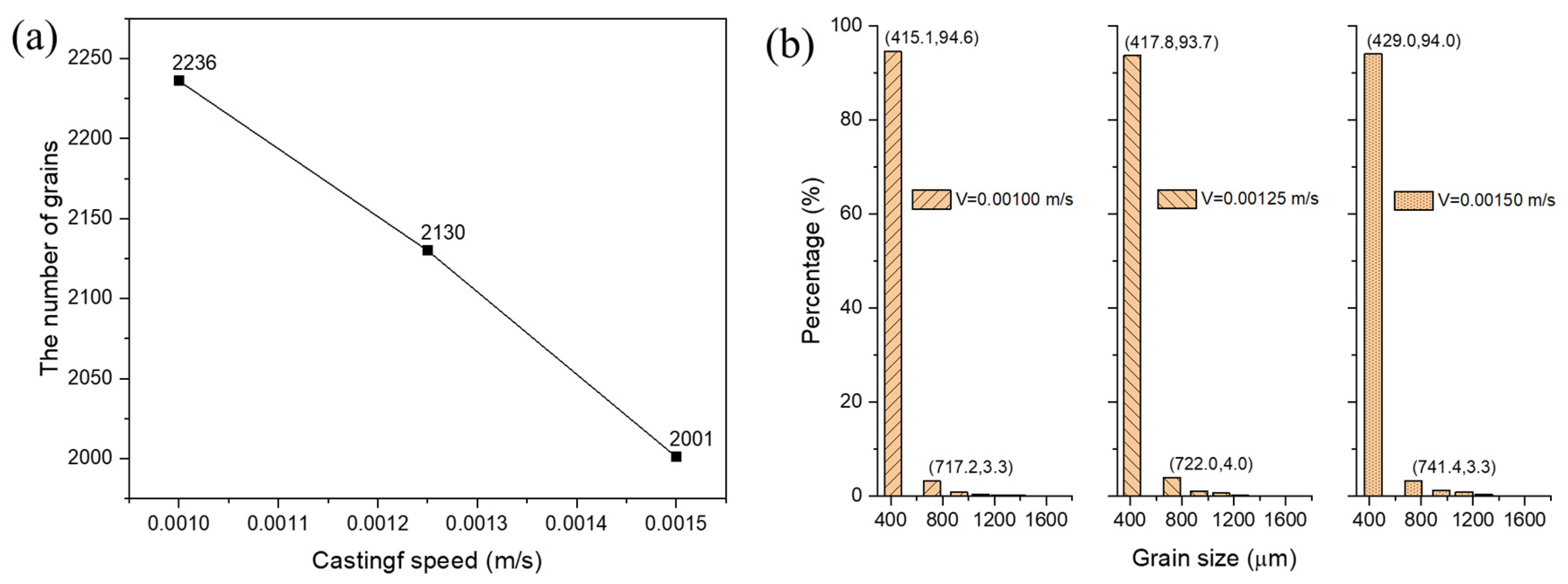
4.2. The Effect of Casting Speed on Solidification Structure Evolution
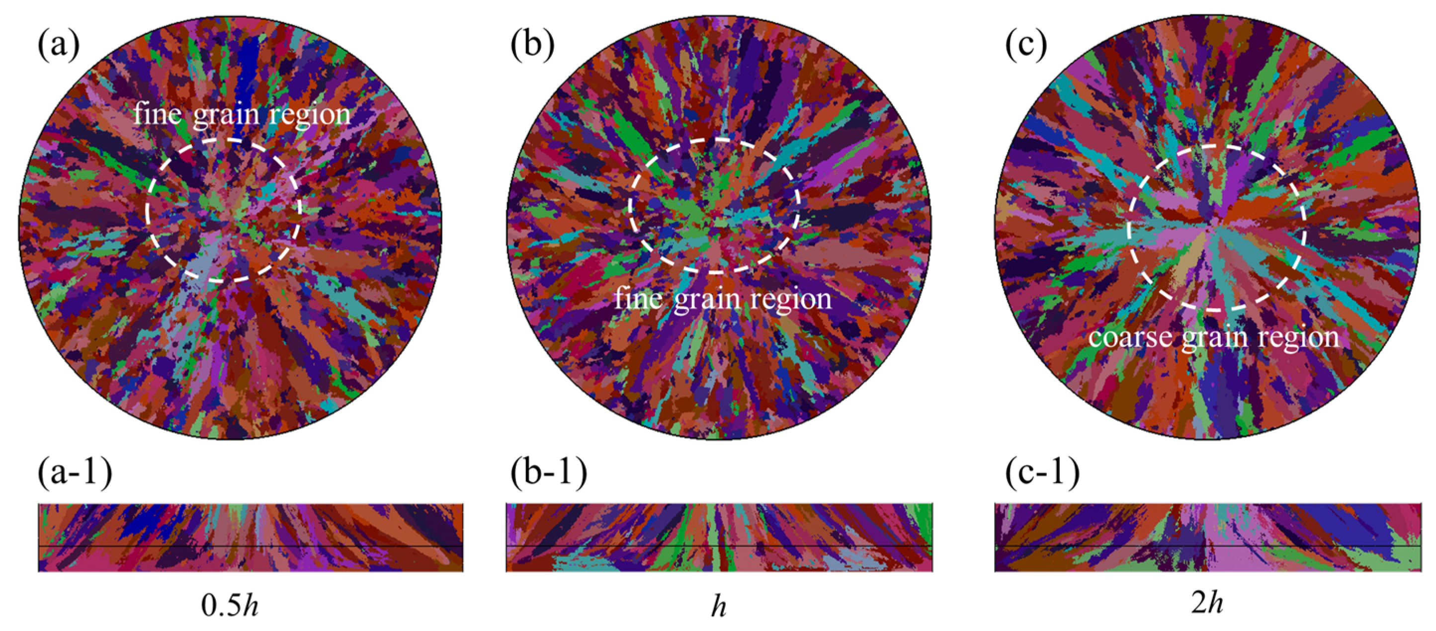
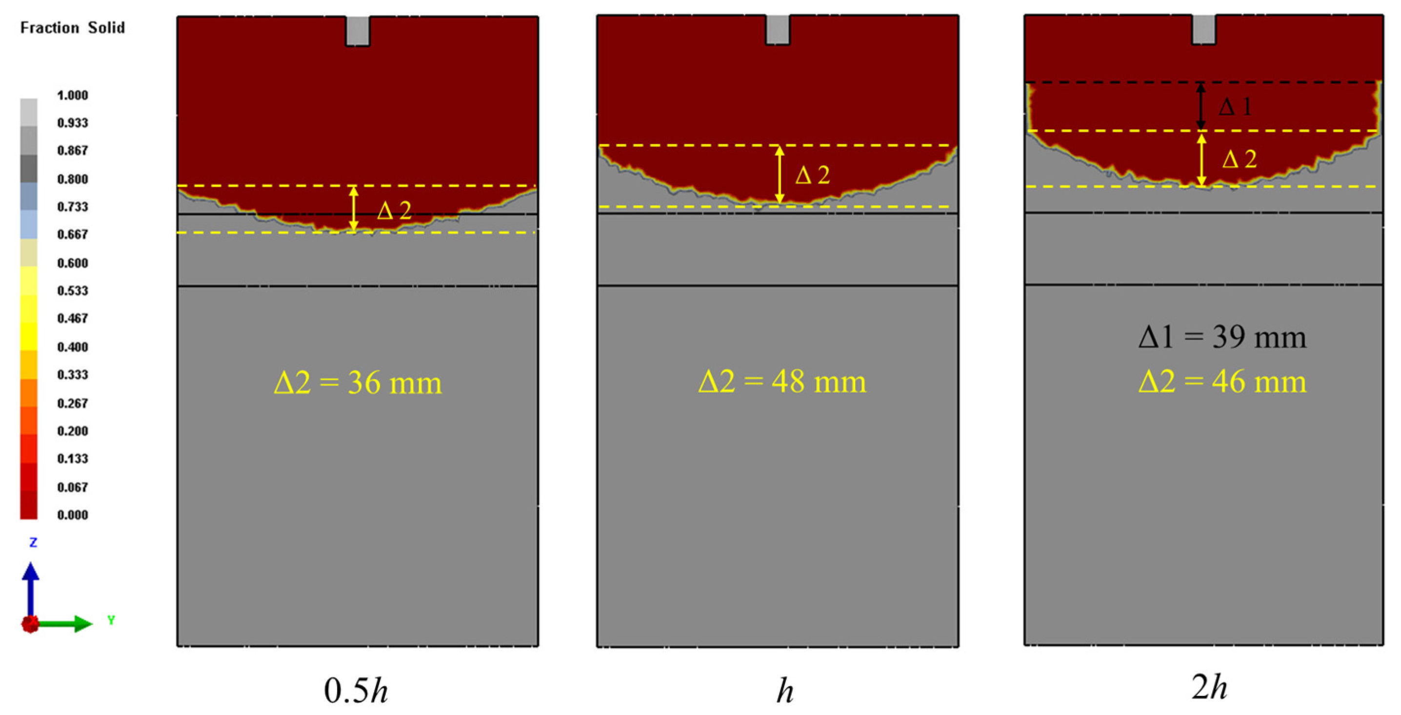
4.3. The Effect of Heat Transfer Coefficient on Solidification Structure Evolution
5. Conclusions
- (1)
- With the increase of casting temperature, the depth of liquid sump increases gradually, but the height of the S/L interface decreases. The grain size decreases first and then increases. There is a compromise between grain size and its uniformity; the grain size is more uniform at higher casting temperature.
- (2)
- With the casting speed increasing, the depth of liquid sump and the height of the S/L interface increase, but the total grain number of the billet cross-section decreases gradually. The structural uniformity of billet is better at lower casting speed.
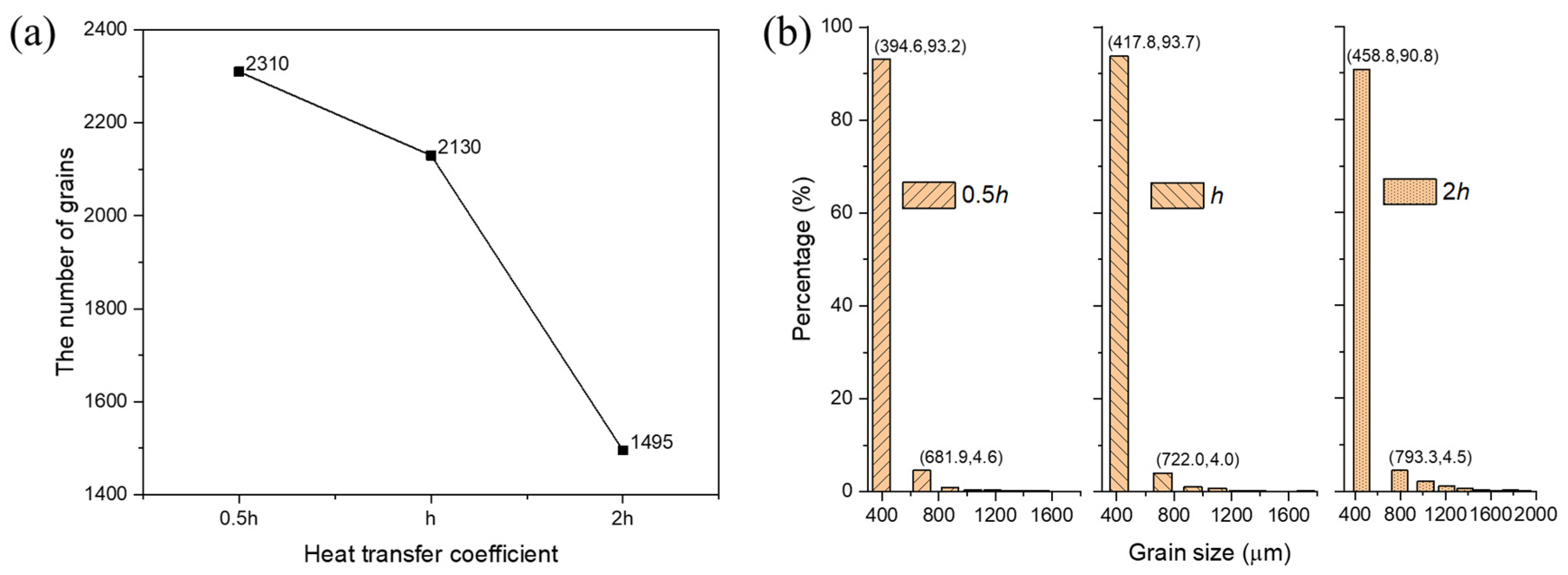
- (3)
- As the heat transfer coefficient increases, the depth of the casting liquid sump becomes shallow, but the height of the solid–liquid interface increases and the grain size increases gradually.
- (4)
- For the preparation of high purity copper billets with large cross-sectional dimensions by DC casting, a fine solidified structure can be obtained by appropriately reducing the casting speed and cooling intensity.
Author Contributions
Funding
Acknowledgments
Conflicts of Interest
References
- Hu, C.-K.; Harper, J.M.E. Copper interconnections and reliability. Mater. Chem. Phys. 1998, 52, 5–16. [Google Scholar] [CrossRef]
- Han, S.Z.; Lee, J.; Lim, S.H.; Ahn, J.H.; Kim, K.; Kim, S. Optimization of conductivity and strength in Cu-Ni-Si alloys by suppressing discontinuous precipitation. Met. Mater. Int. 2016, 22, 1049–1054. [Google Scholar] [CrossRef]
- Fu, H.; Xu, S.; Li, W.; Xie, J.; Zhao, H.; Pan, Z. Effect of rolling and aging processes on microstructure and properties of Cu-Cr-Zr alloy. Mater. Sci. Eng. A 2017, 700, 107–115. [Google Scholar] [CrossRef]
- Lei, Q.; Li, Z.; Gao, Y.; Peng, X.; Derby, B. Microstructure and mechanical properties of a high strength Cu-Ni-Si alloy treated by combined aging processes. J. Alloys Compd. 2017, 695, 2413–2423. [Google Scholar] [CrossRef]
- Li, C.; Le, Q.; Hu, K.; Bao, L.; Ma, B.; Jia, Y.; Wang, X.; Zhou, W.; Xu, G. Study on texture and dynamic recrystallization behavior of high purity copper during reverse extrusion. Mater. Res. Express 2020, 6, 1265e4. [Google Scholar] [CrossRef]
- Yu, H.; Wang, L.; Chai, L.; Li, J.; Lu, C.; Godbole, A.; Wang, H.; Kong, C. High thermal stability and excellent mechanical properties of ultrafine-grained high-purity copper sheets subjected to asymmetric cryorolling. Mater. Charact. 2019, 153, 34–45. [Google Scholar] [CrossRef]
- Yu, Z. Development and Current Tendency of High Purity Copper Sputtering Targets. Shanxi Metall. 2007, 5, 4–6. [Google Scholar]
- Shang, Z.; Jiang, X.; LI, Y.; Yang, Y. Sputtering targets used in integrated circuit. Chin. J. Rare Met. 2005, 29, 475–477. [Google Scholar]
- Lo, C.F.; Draper, D. Method for Fabricating Randomly Oriented Aluminum Alloy Sputting Targets with Fine Grains and Fine Precipitates. U.S. Patent No 5,993,575, 30 November 1999. [Google Scholar]
- Liu, X.; Liao, W.; Yang, Y. Thermal characteristics and uniformity of microstructures during temperature controlled mold continuous casting profiled copper alloy strip. Int. Commun. Heat Mass Transf. 2020, 110, 104414. [Google Scholar] [CrossRef]
- Tsai, D.C.; Hwang, W.S. Numerical simulation of the solidification processes of copper during vacuum continuous casting. J. Cryst. Growth 2012, 343, 45–54. [Google Scholar] [CrossRef]
- Fu, Y.; Jie, C.; Ning, L.; Luo, D.; Yin, G. Preparation of large sized billets of 99.999% ultrahigh-purity copper by directional solidification directing vacuum melting. Rare Met. Mater. Eng. 2011, 40, 103–106. [Google Scholar]
- Xu, G.; Chen, G.; Yao, Y.; Luo, Y. The new technology of continuous extrusion oxygen-free copper bar. Spec. Cast. Nonferrous Alloys. 2014, 34, 559–560. [Google Scholar]
- Stefanescu, D.M. Science and Engineering of Casting Solidification, 2nd ed.; Springer: Berlin, Germany, 2009. [Google Scholar]
- Rappaz, M.; Gandin, C.-A. Probabilistic modelling of microstructure formation in solidification processes. Acta Metall. Et Mater. 1993, 41, 345–360. [Google Scholar] [CrossRef]
- Wang, T.; Wei, J.; Wang, X.; Yao, M. Progress and application of microstructure simulation of alloy solidification. Acta Metallurgica Sinica 2017, 54, 193–203. [Google Scholar]
- Luo, S.; Zhu, M.; Louhenkilpi, S. Numerical Simulation of Solidification Structure of High Carbon Steel in Continuous Casting Using Cellular Automaton Method. ISIJ Int. 2012, 52, 823–830. [Google Scholar] [CrossRef] [Green Version]
- Tsai, D.-C.; Hsu, M.-S.; Hwang, W.-S.; Jiang, C.-S. Mathematical Modeling of Solidification Microstructure of Pure Copper by Vacuum Continuous Casting and Its Experimental Verification. ISIJ Int. 2010, 50, 1843–1850. [Google Scholar] [CrossRef] [Green Version]
- Hou, Z.; Jiang, F.; Cheng, G. Solidification Structure and Compactness Degree of Central Equiaxed Grain Zone in Continuous Casting Billet Using Cellular Automaton-Finite Element Method. ISIJ Int. 2012, 52, 1301–1309. [Google Scholar] [CrossRef] [Green Version]
- Li, B.; Wang, Q.; Wang, F.; Chen, M. A Coupled Cellular Automaton–Finite-Element Mathematical Model for the Multiscale Phenomena of Electroslag Remelting H13 Die Steel Ingot. JOM 2014, 66, 1153–1165. [Google Scholar] [CrossRef]
- Skrzypczak, T. Sharp Interface Numerical Modeling of Solidification Process of Pure Metal. Arch. Metall. Mater. 2012, 57, 1189–1199. [Google Scholar] [CrossRef] [Green Version]
- Kurz, W.; Giovanola, B.; Trivedi, R. Theory of microstructural development during rapid solidification. Acta Met. 1986, 34, 823–830. [Google Scholar] [CrossRef]
- Gandin, C.-A.; Rappaz, M. Coupled finite element-cellular automation model for the prediction of dendritic grain structures in solification processes. Acta Metall. Et Mater. 1994, 42, 2233–2246. [Google Scholar] [CrossRef]
- Beddoes, J.; Bibby, M.J. Solidification and casting processes. In Principles of Metal Manufacturing Processes; Butterworth-Heinemann: Oxford, UK, 1999; pp. 18–66. ISBN 978-0-340-73162-8. [Google Scholar]
- Kurz, W.; Fisher, D.J. Foundamentals of Solidification, 2nd ed.; Trans Tech Publications: Stafa-Zurich, Switzerland, 1989. [Google Scholar]
- Pryds, N.H.; Huang, X. The effect of cooling rate on the microstructures formed during solidification of ferritic steel. Met. Mat Trans A 2000, 31, 3155–3166. [Google Scholar] [CrossRef]
- Karakulak, E. A review: Past, present and future of grain refining of magnesium castings. J. Magnes. Alloy. 2019, 7, 355–369. [Google Scholar] [CrossRef]
- Ali, Y.; You, G.; Pan, F.; Zhang, M.-X. Grain Coarsening of Cast Magnesium Alloys at High Cooling Rate: A New Observation. Met. Mat Trans A 2017, 48, 474–481. [Google Scholar] [CrossRef]


| Parameters | Values |
|---|---|
| Diameter of the billet (m) | 0.300 |
| Height of the billet (m) | 0.525 |
| Height of the mold (m) | 0.265 |
| Liquidus (°C) | 1085 |
| Solidus (°C) | 1084 |
| Casting temperature, (°C) | 1150 |
| 1175 | |
| 1200 | |
| 1225 | |
| 1250 | |
| Casting speed (m/s) | 0.00100 |
| 0.00125 | |
| 0.00150 | |
| The intensity of cooling water (W/(m2·K)) | 0.5h (Figure 2) |
| h (Figure 2) | |
| 2h (Figure 2) |
| Cell size (μm) | Number of Cells in a Block | Nucleation Parameters | |||||
|---|---|---|---|---|---|---|---|
| Volume Nucleation | Surface Nucleation | ||||||
(°C) | (°C) | (m−3) | (m−3) | (°C) | (m−2) | ||
| 600 | 10 × 10 × 10 | 1 | 0.1 | 2 × 10⁶ | 0.1 | 0.1 | 5 × 10⁴ |
© 2020 by the authors. Licensee MDPI, Basel, Switzerland. This article is an open access article distributed under the terms and conditions of the Creative Commons Attribution (CC BY) license (http://creativecommons.org/licenses/by/4.0/).
Share and Cite
Jia, Y.; Zhao, D.; Li, C.; Bao, L.; Le, Q.; Wang, H.; Wang, X. Study on Solidification Structure Evolution of Direct-Chill Casting High Purity Copper Billet Using Cellular Automaton-Finite Element Method. Metals 2020, 10, 1052. https://0-doi-org.brum.beds.ac.uk/10.3390/met10081052
Jia Y, Zhao D, Li C, Bao L, Le Q, Wang H, Wang X. Study on Solidification Structure Evolution of Direct-Chill Casting High Purity Copper Billet Using Cellular Automaton-Finite Element Method. Metals. 2020; 10(8):1052. https://0-doi-org.brum.beds.ac.uk/10.3390/met10081052
Chicago/Turabian StyleJia, Yonghui, Dazhi Zhao, Chunyu Li, Lei Bao, Qichi Le, Hang Wang, and Xuan Wang. 2020. "Study on Solidification Structure Evolution of Direct-Chill Casting High Purity Copper Billet Using Cellular Automaton-Finite Element Method" Metals 10, no. 8: 1052. https://0-doi-org.brum.beds.ac.uk/10.3390/met10081052