Article

Renewable Hydrogen Production Processes for the Off-Gas Valorization in Integrated Steelworks through Hydrogen Intensified Methane and Methanol Syntheses

1
Scuola Superiore Sant’Anna, TeCIP Institute, Via Moruzzi 1, 56124 Pisa, Italy
2
Chemical Process and Energy Resources Institute (CPERI), Centre for Research and Technology Hellas (CERTH), 6th km. Charilaou-Thermi, 57001 Thessaloniki, Greece
*
Author to whom correspondence should be addressed.
Submission received: 3 November 2020 / Revised: 14 November 2020 / Accepted: 16 November 2020 / Published: 18 November 2020

Abstract

:
Within integrated steelmaking industries significant research efforts are devoted to the efficient use of resources and the reduction of CO2 emissions. Integrated steelworks consume a considerable quantity of raw materials and produce a high amount of by-products, such as off-gases, currently used for the internal production of heat, steam or electricity. These off-gases can be further valorized as feedstock for methane and methanol syntheses, but their hydrogen content is often inadequate to reach high conversions in synthesis processes. The addition of hydrogen is fundamental and a suitable hydrogen production process must be selected to obtain advantages in process economy and sustainability. This paper presents a comparative analysis of different hydrogen production processes from renewable energy, namely polymer electrolyte membrane electrolysis, solid oxide electrolyze cell electrolysis, and biomass gasification. Aspen Plus® V11-based models were developed, and simulations were conducted for sensitivity analyses to acquire useful information related to the process behavior. Advantages and disadvantages for each considered process were highlighted. In addition, the integration of the analyzed hydrogen production methods with methane and methanol syntheses is analyzed through further Aspen Plus®-based simulations. The pros and cons of the different hydrogen production options coupled with methane and methanol syntheses included in steelmaking industries are analyzed.

1. Introduction

The steel industry is energy intensive, being the second-largest industrial energy consumer and one of the most relevant CO2 emission sources [1,2]. Steel production is mainly based on fossil fuels for energy supply and accounts for about 4–5% of total world CO2 emissions [3,4]. In particular, for every ton of steel produced, 1.9 tons of CO2 are emitted [4].
The primary steel production in integrated steelworks needs more energy than the steel manufacturing in electric arc furnace (EAF), where scrap is used and no chemical energy to reduce iron ore is necessary [5]. The blast furnace (BF) and the basic oxygen furnace (BOF) exploit an amount of energy in the range of 13–14 GJ/t of produced steel, while the scrap/EAF route needs 4–6 GJ per ton of produced steel [6]. Generally, in the steelworks energy costs account for about 20% of the total operation costs [7,8].
The ever increasing international attention toward environmental issues, landscape and health protection, as well as tightening of environmental regulations, exert a further pressure on steel companies in order to increase the sustainability of their production cycles [9]. During the last United Nations Climate Change Conference in Paris (COP 25), governments around the world approved that international climate policy should limit the increase of global average temperature to less than 2 °C with respect to pre-industrial period [10]. To reach this target a substantial reduction of anthropogenic green house gases (GHG) emissions is required in all sectors. European process industries are therefore focusing many actions and research activities toward the optimization of resource management and the reduction of climate-changing emissions. In this scenario, it is undeniable that the European steel industry is committed to achieve important objectives in terms of production costs, environmental impact, and sustainability [4]. This can be observed, for instance, in the work described in [11] where different simulation techniques have been exploited for analyzing future scenarios dedicated to improving the management of water or solid by-products streams in integrated steelmaking. The importance of improving the sustainability of steelworks, including the electric one, is also evident in the work presented in [12], where Aspen Plus® simulation model is applied in order to study the correlations among electric energy consumption, steel grade, slag quantity, and composition. The objectives of sustainability and reduction of costs are usually linked, as an efficient use of energy and resources allows reducing production costs, GHG emissions and environmental impact [13]. Therefore, energy saving is essential to guarantee the competitiveness of steel companies, as it also entails significant reductions of operative costs [2,5]. Over the last few decades, the steel industry has reduced its energy consumption by 50%. Currently, significant further reductions of the fossil fuel derived energy consumption and carbon emissions cannot be achieved unless introducing breakthrough steelmaking technologies that can use renewable energy most likely in the form of hydrogen [4].
Integrated steelworks are relevant resource consumers, but they also produce an important volume of by-products, among which are the off-gases. A correct and efficient management of all by-products [14], including process gases, can play a decisive role in increasing the economic and environmental sustainability of the integrated steel production route [15].
Process off-gases are generated in the three main steps of steel production in an integrated steel plant: Coke oven gas (COG), blast furnace gas (BFG), and basic oxygen furnace gas (BOFG). These by-products are a very precious source of energy and a valid alternative to natural gas (NG) in several operations: They can be exploited to meet the energy demand of production processes, to produce steam and as energy sources for power plants, which can both satisfy internal electricity demand and offer part of their production to the external energy market [16]. The formation of off-gases is obviously related to production steps and it cannot be avoided, but a reliable prediction of its production or demand can improve their management and reuse, as shown in detail in [17], where the description of two models based on Echo State Neural Networks (ESN) is reported. These models aim to forecast the amount and energy content of BFG and its demand by main users, in order to obtain useful information for the optimization of the off-gases management by a decision support system. The strong interaction between production scheduling and off-gases network makes the management of these by-products very complex, and their distribution is often difficult to optimize, as discussed by Maddaloni et al. [18], who presented a quadratic programming for the optimization of off-gas management. In particular, when an overproduction of off-gases occurs, the excess gas needs to be flared with consequent waste of energy and CO2 emissions, while, when their production is not sufficient to meet the demand, NG is used leading to economic and environmental costs. An optimal exploitation of those off-gases plays a crucial role in integrated steelworks sustainability. Therefore, in the last few years, companies and research institutions have developed several projects, aimed at investigating the best use of this important resource. For instance, a decision support system based on flowsheeting static models forecasting gas consumption and demands was developed by Porzio et al. in [19]. Multi-objective optimization techniques have been intensively applied to find optimal distribution of process gases, such as Genetic Algorithms (GA) [20] and Mixed Integer Linear Programming (MILP) [21,22], which are suitable to face the multiple and often complex constraints which characterize this optimization problem and allow considering also the cost of gas network structural modifications [20]. Further studies compared such approaches [23], while a more recent study introduced multi-period optimization to this purpose [24].
A step ahead in the internal off-gas optimized management was carried out in the project co-funded by the European Union through the Research Fund for Coal and Steel (RFCS), which is entitled “Optimization of the management of the process gases network within the integrated steelworks—GASNET” [17,18,25]. Within this project a Decision Support System (DSS) was developed helping plant managers to optimally exploit process off-gases by minimizing energy wastes and flaring and considering environmental and economic constraints as well as synergies among producers and consumers of gas, heat, electricity, and steam.
As far as the utilization of integrated steelworks off-gases within different chemical processes is concerned, Maruoka and Akiyama in [26] investigated the topics of methanol production by first steps of methane production through steam reforming and ad-hoc energy recovery process. Other works have also aimed at investigating the use of exhaust gases for the production of chemical substances, as analyzed in [27]. Some recent projects and researches, such as VALORCO [28], Carbon2Chem [29], Renewable-Steel-Gases [30], and the works of Kim and Han [31], of Gao et al. [32], and of Shin et al. [33], were dedicated to the production of methane, methanol, ammonia and other chemicals through adequate exploitation of off-gases. However, often the composition of these gases is not suitable to reach high reaction yield in the production of methane and methanol. Indeed, the content of hydrogen (H2) in off-gases is often insufficient to reach the required stoichiometric ratio for the reactions involved in the methane and methanol productions. To avoid this problem, the addition of further H2 is a key element in methane and methanol syntheses when steelworks off-gases are used as feed. Therefore, a suitable hydrogen production process must be selected in order to obtain advantages in terms of process economy and sustainability.
The work presented in this paper is part of the project entitled “Integrated and intelligent upgrade of carbon sources through hydrogen addition for the steel industry (i3upgrade)” co-founded by the European Union through the RFCS, which aims at valorizing off-gases for the production of methane and methanol through the improvement of steelworks off-gases by adding hydrogen. In this way, besides economic advantages, carbon dioxide emissions can be reduced, if added H2 is produced through “green” technologies. The CO2 emission reduction is obviously not only obtained through a suitable technology choice for H2 production, but it is also due to the adopted system operating conditions and to the exploitation of renewable material and energy sources.
In particular, the paper presents a comparative analysis of different H2 production processes exploiting renewable sources for identifying advantages and limitations for their integration in methane and methanol syntheses, whose investigation is also introduced in the paper. The selected and investigated processes are polymer electrolyte membrane (PEM) electrolysis, solid oxide electrolyzer cell (SOEC) electrolysis and biomass gasification. The comparison was carried out through Aspen Plus® V11-based simulations exploiting ad-hoc developed models. Sensitivity analyses have been carried out in order to analyze the modelled processes’ behavior at different operating conditions.
The main novelties of the proposed work lie in the modelling approach adopted for the three considered technologies for green hydrogen production that allow both a comprehensive analysis of the considered technologies and especially the integration of the developed models with further models related to methanol and methane syntheses, as well as in the carried out simulation analyses. In order to consider a credible inclusion in the steel industrial context, some realistic scenarios are analyzed related to a medium size integrated steelmaking plant regarding different utilization options of the off-gases.
The paper is organized as follows: Section 2 presents a state-of-the-art related to technologies of H2 production with low environmental impact and suitable for integration in steelworks. It also contains a brief summary of methane and methanol syntheses. In Section 3 the Aspen Plus®-based simulations of the selected hydrogen production methods are reported and their integration in methane and methanol synthesis of steelworks off-gases is introduced. Section 4 discusses the main results and Section 5 reports the main concluding remarks of this work.

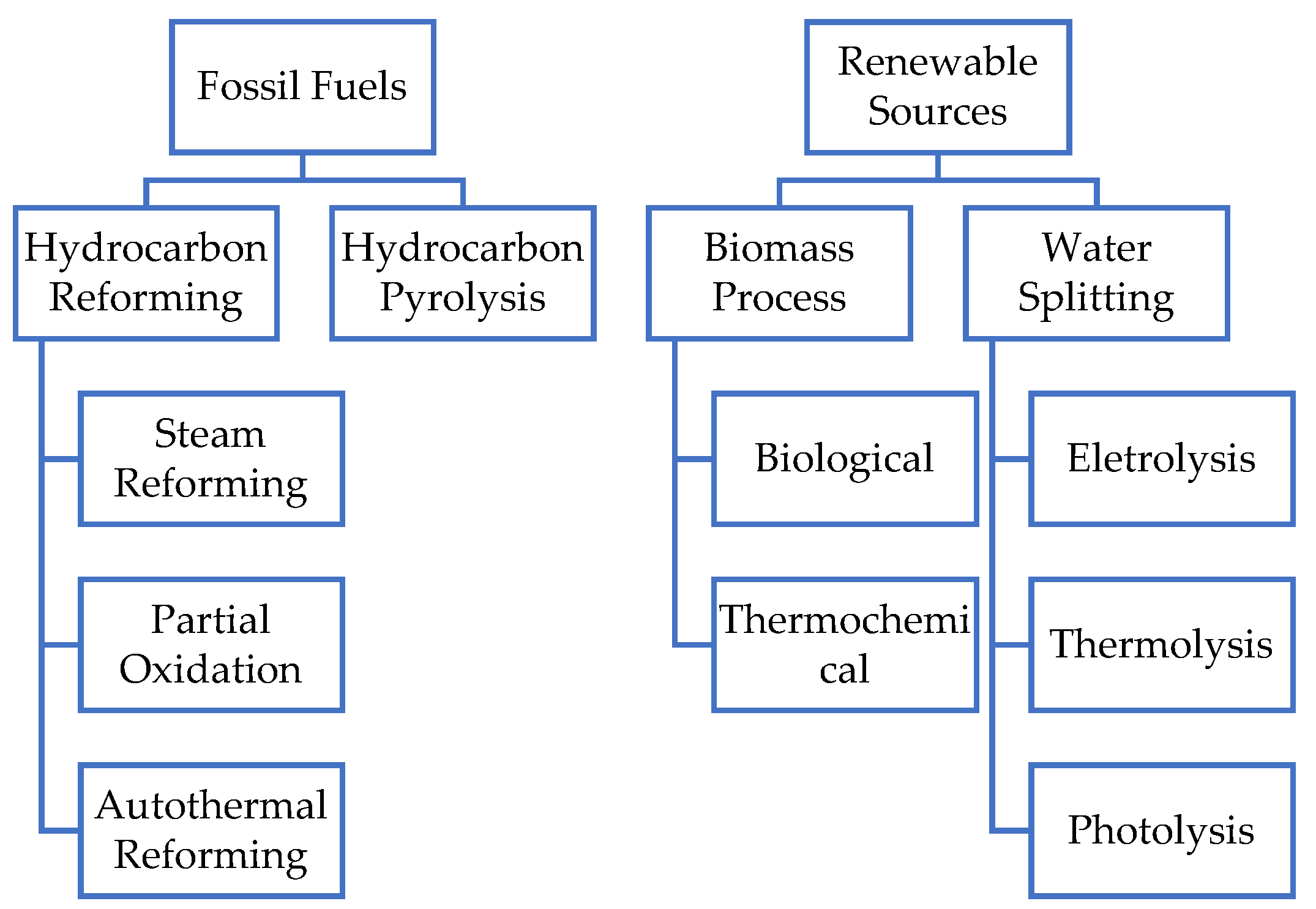
2. Sustainable Hydrogen Production
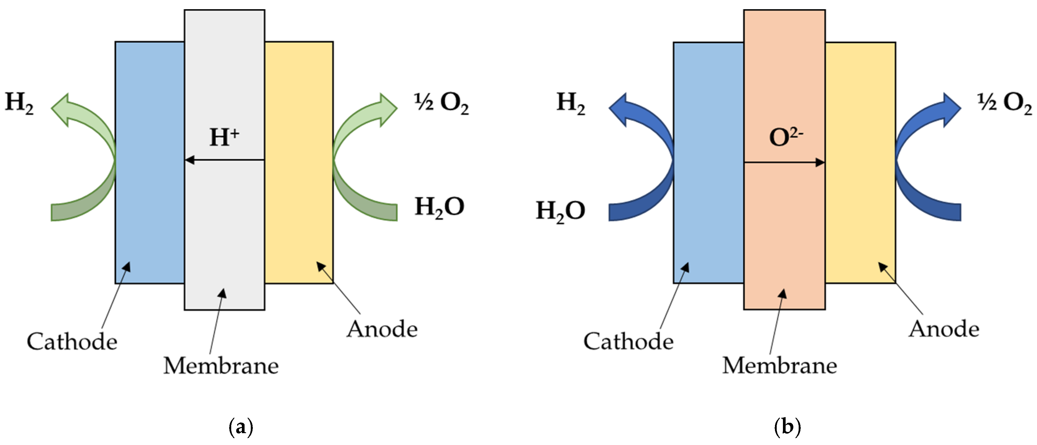
Hydrogen is a clean gas and a source of environmentally friendly energy, but it is not easily obtainable in nature. There are different processes for hydrogen production from conventional and alternative energy sources, as schematically summarized in Figure 1 [34]. Presently, the global hydrogen production mainly derives from fossil fuels and the most developed technologies are pyrolysis [34] and hydrocarbon reforming, such as steam methane reforming (SMR) that is the most common and cheapest method used to produce hydrogen in large scale [35,36].
In the present work, an accurate literature analysis [34,37,38,39,40,41,42,43,44,45] has been conducted in order to study and compare different techniques for the hydrogen production. According to the state-of-the-art investigation, water electrolysis and biomass gasification are the most promising sustainable technologies with low environmental impact and with an appropriate development degree for the integration in steelworks. The following two subparagraphs provide a description of both approaches.

2.1. Electrolysis

Water electrolysis is an electrochemical process: The water is separated in hydrogen and oxygen by exploiting electrical and thermal energy [46]. The anode and the cathode are immersed in the electrolytes and the separation of hydrogen takes place when electrical current is applied [34]: At the cathode the reduction occurs and the hydrogen is produced, while at the anode an oxidation reaction allows the production of oxygen [47].
This technology produces hydrogen with very high purity without carbon and sulfur contamination [36,46]. The main issues are Joule effect and parasite reactions within solution that cause high-power dissipation with a consequent costs increase [48].
The electrolysis technique is generally indicated for producing hydrogen close to the users, especially due to the compactness of the required plant, and for small-scale applications [36]. This process is energy intensive, but can be coupled to renewable energy sources in order to achieve a completely “green” and sustainable hydrogen production [49]. Considering these aspects, the renewable hydrogen system can be one of the solutions to be followed to obtain hydrogen without impact on carbon footprint. In addition, the use of solar and wind energy with hydrogen storage system can result in using renewable and clean resources as well as in environmental protection [39].
There are different technologies for electrolysis process, the main are: Low temperature (70–90 °C) alkaline electrolysis (AEL), proton exchange membrane (PEM), and high temperature (650–850 °C) solid oxyde electrolyzers cells (SOEC). In particular, the last two methods are more suitable for the purpose of the present investigation, as AEL is sensitive to the effects of fluctuations in power supply (i.e., in the case of renewables): Its efficiency is compromised by presenting large inertia in transporting ions [50]. A further pioneering technology is anion exchange membrane (AEM) electrolysis. The AEM combines the low cost of alkaline electrolysis and the high power of PEM, but this technology is still under development [51].

2.1.1. PEM Electrolysis

The PEM electrolysis is characterized by the use of thin splitting polymer membrane of Nafion® instead of the electrolytic liquid in the AEL process. The thickness of the membrane is usually 0.2 mm to ensure a close proximity of the electrodes [52,53]. A simplified scheme of PEM is depicted in Figure 2a.
At the anode the oxidation of water occurs, as follows:
H 2 O     1 2   O 2   +   2 H +   +   2 e .
At the cathode, the hydrogen ions are reduced, according to the following reaction, and pass through the membrane [52,53]:
2H+ + 2e → H2.
In general, the following operating conditions hold for PEM:
  • Operation temperature To = 40 ÷ 80 °C [52,54,55];
  • pressure of the cathode section Pcat < 35 bar [52,56];
  • pressure of the anode section Pan < 3.5 bar [52,56];
  • fresh water consumption of 0.9 ÷ 1 L of H2O/Nm3 of H2 (10.1 ÷ 11.2 kg of H2O/kg of H2) [57,58,59,60]; and
  • energy demand of 54 ÷ 80 kWh/kg of H2 [55,57,58,59,61].
PEM is not sensitive to the effects of fluctuations in power supply thanks to the rapid response of the proton transport across the polymeric membrane. For this reason, it is suitable to the use when renewable energy sources are available. On the other hand, the investment costs are high, as the membranes and the electrodes are composed of noble metals [50].

2.1.2. SOEC Electrolysis

The SOEC electrolysis is composed by three-layer solid structure (porous cathode, electrolyte, and porous anode) and an interconnect plate as shown in Figure 2b [45,62].
The steam at high temperature is introduced at the cathode side and reduced into hydrogen, producing oxide anions, according to the following reaction:
2H2O + 4e → 2H2 + 2O2−.
At the anode, the oxide anions, that have migrated through the electrolyte, are combined to form oxygen molecules, releasing electrons, according to the following reaction [45,62]:
2O2− → O2 + 4e.
The SOEC electrolysis operating conditions are:
  • To = 600 ÷ 1000 °C [52,62,63];
  • Pstack = 1 ÷ 30 bar [64];
  • fresh water consumption of 9.1 kg of H2O/kg of H2 [55]; and
  • energy demand of about 50.3 kWh/kg of H2 (i.e., it requires less electric power than other water electrolysis technologies) [55].
This technology allows achieving a higher energy conversion efficiency with respect to other water electrolysis techniques [62]. On the other hand, SOEC technologies need high purity of the water as feedstock to avoid corrosion and early degradation of components [64]. The high temperature operating mode leads to high maintenance costs and generally the SOEC is convenient when a high-temperature heat source is available [52,64].

2.1.3. Hydrogen Production from Biomass

Presently, in the case of hydrogen production from biomass, the most important thermochemical conversion technologies are pyrolysis and gasification [43,65]. Among these technologies, steam gasification can provide the highest yields of hydrogen that can reach 52% (thermal-to-hydrogen) [34].
The biomass gasification process converts biomass into a gaseous fuel (syngas) at high temperature and without combustion with a controlled amount of air, oxygen and/or steam [34,66].
Bio-syngas contains mostly CO and H2, and the other elements are CO2, CH4, light hydrocarbons (HC), coal, and tar [43,67]. Absorbers and special membranes are generally exploited to separate the hydrogen from the gas stream [66].
The gasification processes of biomass are divided into three main groups (which are summarized in Table 1), depending on the type of gasifying agent [67].
Among the different biomass gasification processes, the steam gasification is the best compromised in terms of hydrogen efficiency and costs for the purpose of this work.

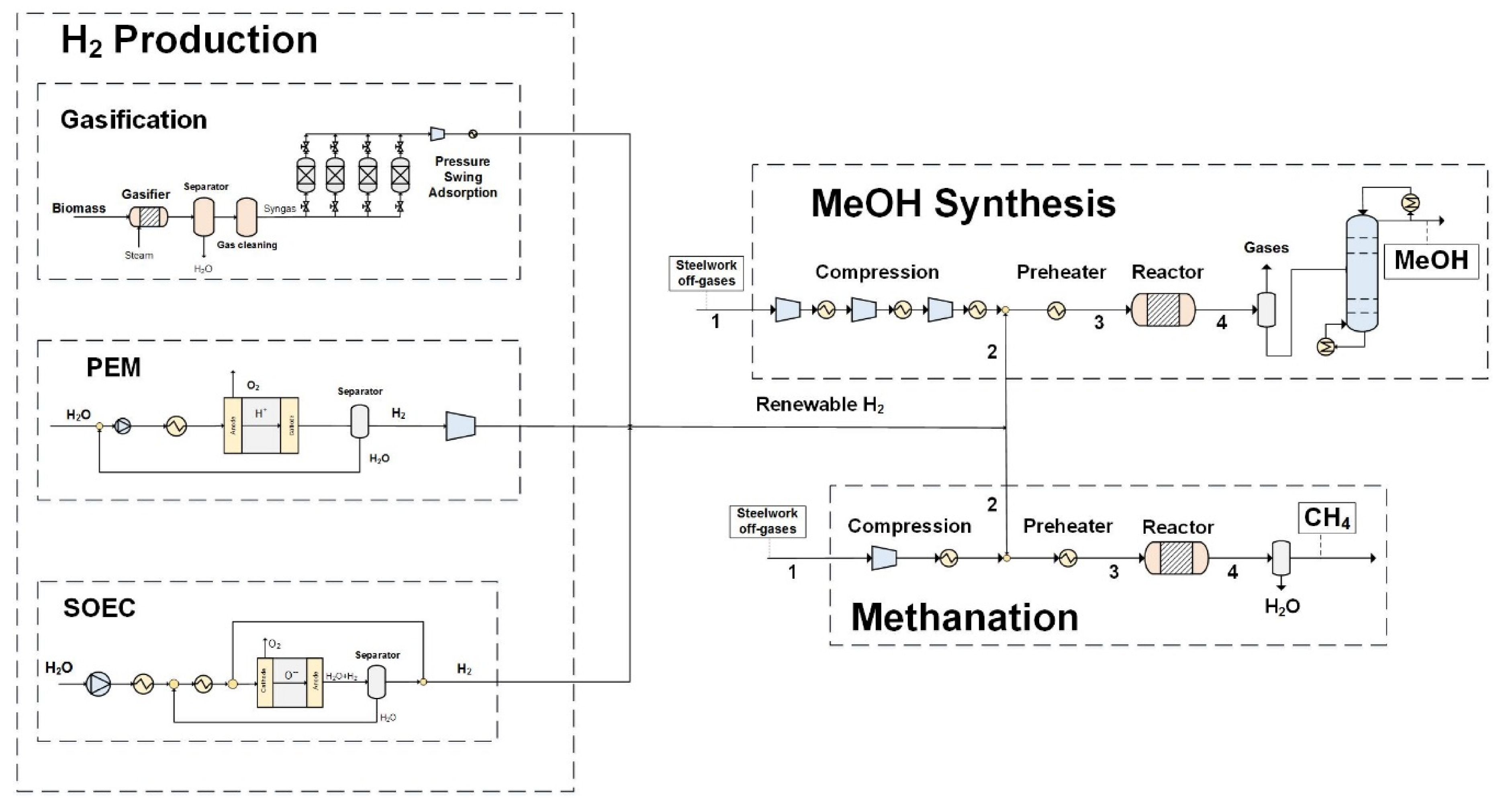
2.2. Integration of Hydrogen Production with Methane and Methanol Synthesis

The integration of the sustainable hydrogen production with methane and methanol synthesis based on steelwork off-gases as feedstock is necessary in order to achieve the required stoichiometric ratio because the compositions of steelworks gases are often not suitable without hydrogen addition. The typical volume compositions of steelworks process gases are:
  • BFG: CO 23%, H2 4.5%, CO2 21%, N2 51%;
  • BOFG: CO 60.9%, H2 4.3%, CO2 17.2%, N2 15.5%, CH4 0.1%; and
  • COG: CO 4.6%, H2 48.9%, CO2 3.2%, N2 3.75%, CH4 21.35%, CxHy 1.9% [16].
The methanation is a method to obtain methane from carbon monoxide and carbon dioxide with the addition of the required stoichiometric hydrogen. In the last few years this process has gained the attention of researchers as it is considered a promising solution to store energy in future energy systems. Therefore, many recent studies and projects are studying the possibility of improving this technology or simplifying the process itself to make it competitive. For instance, Neubert et al. in [68] proposes a new catalytic methanation reactor with heat pipe integration into a structured reactor, that can be considered suitable alternatives to classical reactors for CO2 methanation due its efficient temperature control; Leimert et al. in [69] suggests the combination of heat pipe reformer biomass gasification process with hydrogen intensified methanation. Further studies on the production of methane from biomass are reported in [70,71,72], as well as from COG in [73]. In this last work the use of COG for methanol (MeOH) synthesis is also described. The catalytic methanol synthesis is exothermic and thermodynamically favored by lower temperatures and higher pressures. Today most of the world methanol production is covered with natural gas derived synthesis gas that after H2/CO ratio adjustment is catalytically processed at 50–100 bar and temperatures between 200–300 °C (temperatures required for the activation of the employed catalyst). The stoichiometric number ( S N ) characterizes the hydrogen input related to CO and CO2 components for MeOH synthesis:
S N = [ H 2 ] [ C O 2 ] [ C O ] [ C O 2 ]
where [ H 2 ] , [ C O ] and [ C O 2 ] denote the molar flows of the feed components. If SN = 2, the reaction is stoichiometric, although the most favorable case is slightly over-stoichiometric [74]. Methanol synthesis normally results in conversion close to what the thermodynamic equilibrium regulates. Thus, any additional input hydrogen is not consumed in the process and remains unexploited in the product gases [75]. Table 2 shows the reaction equations for the methane and methanol syntheses from CO and CO2 [69,76].

3. Materials and Methods

The software Aspen Plus® was adopted for the simulation of hydrogen production with the selected renewable technologies. In the following paragraphs each model is described.

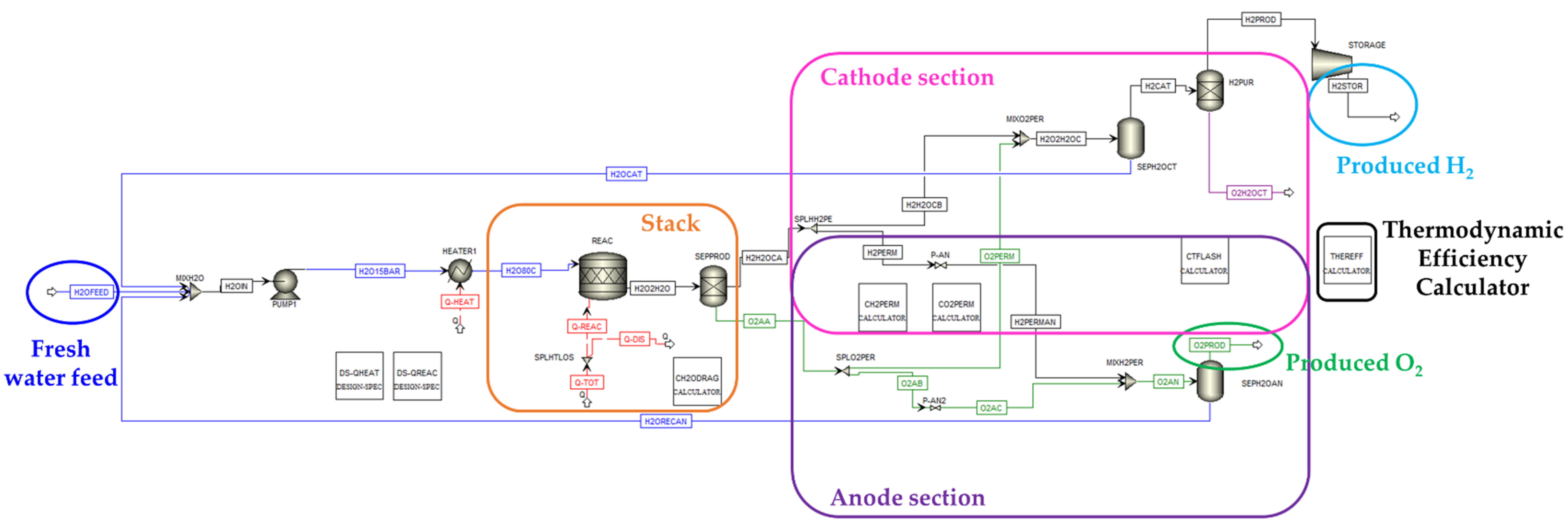
3.1. PEM Electrolysis

The model has been developed, tuned and validated by considering both literature data [52,53,54,55,56,64] and producers’ information [57,58,59,60,61,77]; some assumptions and simplifications have been carried out. The model is stationary and the Aspen Plus® flowsheet is depicted in Figure 3.
The input stream of the model is fresh water, which is assumed to be already deionized, at a temperature of Tin = 25 °C and a pressure Pin = 1 bar. The needed heat is provided in the heater block “HEATER” in order to reach the temperature of 80 °C. Moreover, the values Pcat = 15 bar and Pan = 1.5 bar (10% of cathode section pressure) are considered [52,54,55,56].
The stack is the crucial component in the PEM Electrolysis model; it is represented in the orange square in the Figure 3 and it is where water split reaction occurs. In the reactor “REAC” energy is supplied until the outlet temperature reaches the maximum value of 90 °C (maximum difference between inlet and outlet is set to 10 °C in order to avoid the overheating of the stack) [64].
The hydrogen and oxygen are separated between the cathode and the anode sections. In particular, the permeation of the produced gases through the membrane, which are indicated as H 2 p e r m and O 2 p e r m , respectively, is represented with the combination of separators units and ad-hoc written calculator blocks (i.e., “CH2PERM” and “CO2PERM”) according to the following relations [57,64]:
H 2 p e r m = ( 0.0009 · e 0.025 T ) · Δ P · A
where T is the temperature, ΔP is the pressure difference between cathode and anode, A is the active area (estimated) [54,56].
O 2 p e r m = 0.5 ·   H 2 p e r m
In addition, in order to consider the water dragging by hydrogen ions (protons) from anode to cathode, it is assumed that two moles of water are dragged per mole of hydrogen [56,64,78].
All the steps required for the purification of the hydrogen are included in the cathode section in the fuchsia square in Figure 3. In particular:
  • The flash unit “SEPH2OCT” removes the dragged water, that is recovered and recycled at the inlet of the PEM;
  • the block “H2PUR” represents the last separation step that purifies the hydrogen stream from the remaining water and from the oxygen traces that is permeated from the anode (the molar fraction composition of stream “H2CAT” before the purification is: H2 = 0.951, H2O = 0.048, O2 = 0.001).
On the other hand, the anode section contains the flash unit “SEPH2OAN,” which represents the separation step of water from the produced oxygen (the molar fraction composition of stream “O2PROD” before the separation step is: O2 = 0.867, H2O = 0.133, H2 trace); separated water is recycled.
The final step is the compression of hydrogen to achieve a storage pressure of 30 bar; the related compressor “STORAGE” provides the required power.
A further block is the thermodynamic efficiency calculator “THEREFF,” which calculates the thermodynamic efficiency of the electrolyzer η e l e c t r o l i z e r through the following equation [52]:
η e l e c t r o l i z e r = m H 2 · L C V H 2 E c o n s
where m H 2 is volumetric flow of produced H2 [Nm3/s], L C V H 2 is the low calorific value (LCV) of H2 [MJ/Nm3] and E c o n s is the Total consumed energy [MW].

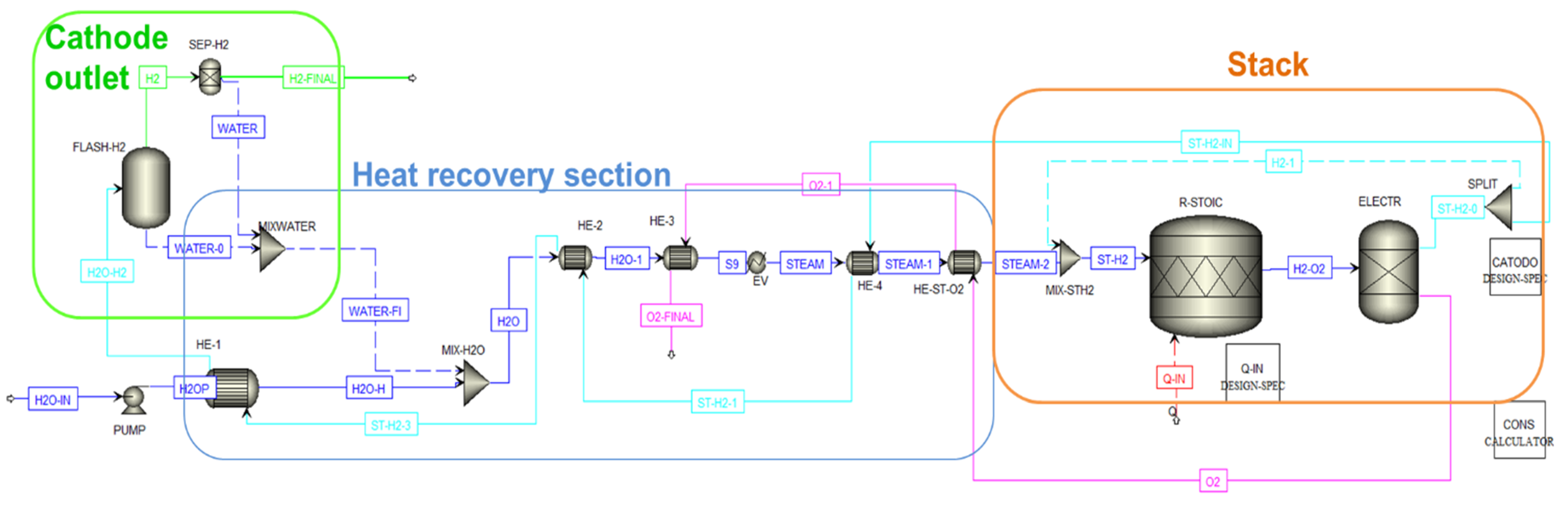
3.2. SOEC Electrolysis

The SOEC model has been built considering the following main assumptions and simplifications:
  • The simulation is developed under the assumption of thermo-neutral conditions [54,64,79];
  • at the cathode outlet of the stack, there is always a mixture of steam and hydrogen because the steam conversion in the stack is lower than 100%, therefore the yield of conversion of steam into hydrogen is fixed at 75% [54,64];
  • SOEC is supposed as an isothermal steady-state system [54,62,80];
  • a fraction of the cathode outlet flow is recirculated to the cathode inlet in order to exploit the hydrogen capacity of counteracting undesired oxidation of the electrodes by the action of pure steam and to preheat the fresh inlet stream [45,54,62,81,82];
  • at the cathode, the flash unit is fed with steam and recycled hydrogen. At the anode, the formation of oxygen is ensured by the recombination of the oxide anions, produced on the cathode and transported through the solid electrolyte [50,83]; and
  • perfect thermal insulation on the stack is considered and heat losses toward the environment are neglected [54].
The Aspen Plus® flowsheet of SOEC model is depicted in Figure 4.
The fresh water already deionized (as high water purity is required [64]), is the input stream of the model with Tin = 20 °C and Pin = 1 bar [55].
The first step of the model is the increasing of the fresh water pressure up to 30 bar [64]. The temperature of the water rises to 749 °C in the heat recovery section (blue frame in Figure 4) and high temperature steam is obtained.
In the stack (orange square in Figure 4), at the operative conditions of 877 °C and 30 bar, the water split occurs [64] and the produced hydrogen and oxygen are separated in the cathode and anode sections of the model. The cathode outlet flow is characterized by a mixture of steam and hydrogen. In order to supply the hydrogen required in the gas feeding mixture (10% mol of H2 and 90% mol of H2O), preventing the oxidation of the electrode material and preheating the feed, a fraction of the cathode outlet flow is sent to the cathode inlet [45,63,83].
In the last step, the pure hydrogen is achieved by condensing the steam in “HE-1” block [54] and separating it from water in the flash unit “FLASH-H2” (stream H2: Mole fraction H2 95%, H2O 5%) followed by the separator block “SEP-H2”. The condensed water is reused in the process [27].
The simulation is carried out considering several literature data with particular attention to the data related to energy and water consumption reported in [55], that are mainly employed for the validation of the model.

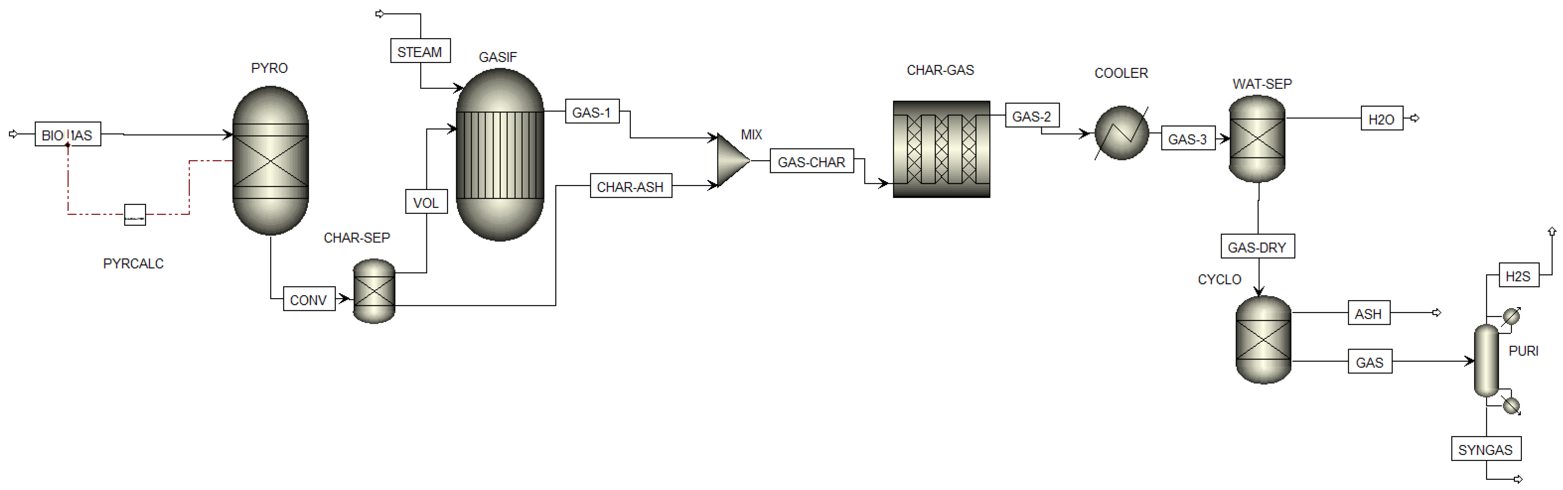
3.3. Biomass Gasification

The biomass gasification model has been developed considering the following main assumptions and simplifications:
  • The process is considered steady state and isothermal;
  • the operations occur at atmospheric pressure (~1 bar);
  • the pressure and temperature are considered uniform inside the gasifier;
  • the heat losses occurring in the gasifier are neglected;
  • the ash and tar formations are neglected: Char has been simplified as pure carbon;
  • sulfur (S) is converted to H2S; and
  • pressure drops are ignored [84,85,86,87].
The biomass input of the model is wood residue with a low content of water, therefore, the drying step is not required. The biomass and the ash are specified as non-conventional components. The proximate analysis and ultimate analysis inserted in Aspen Plus® are illustrated in Table 3 [85].
The Aspen Plus® flowsheet of the model is illustrated in Figure 5. The decomposition of biomass in its chemical compounds (i.e., hydrogen, carbon monoxide, carbon dioxide, oxygen, nitrogen, and sulfur) with pyrolysis process is the first step and it is carried out in the reactor “PYRO”. In the separator block “CHAR-SEP” the separation of solid (char) from volatile part takes place. The steam, which is necessary for the gasification, enters the block “GASI” at 150 °C and 1 atm. The gasification occurs in the reactor “GASI” based on Gibbs free energy minimization by using as calculation option the “Restrict chemical equilibrium”. The reactions are showed in Table 4.
The char gasification occurs in plug flow reactor “CHAR-GAS”, where the kinetic reaction is inserted. The power law reaction kinetic has been used with the parameters reported in [88].
The cleaning of the produced syngas is the last stage of biomass gasification; this stage allows removing water, ash and H2S and obtaining a syngas with high content of hydrogen. It is carried out in the simulation by different separation units in series.
The validation of the model has been conducted using literature data, especially the ones provided by [89].

3.4. Integration of Hydrogen in Methanol and Methane Synthesis

The integration of the three types of renewable hydrogen production, described in previous paragraphs, with methanol and methane syntheses by using steelworks off-gases as feedstock is shown in the simplified overall process flowsheet depicted in Figure 6. In a further part of the work carried out in i3upgrade project, methane and methanol syntheses from steelworks off-gases utilizing renewable hydrogen have been modelled by Aspen Plus®. However, the description of these models is out of the scope of the present paper and only a brief overview is provided here.
The first step for methanol synthesis is the compression to about 70 bar of the feed gas in three stages with intermediate cooling and free water removal to reduce compression costs and avoid unwanted side-effects of liquid water in the machinery and the reactor. Subsequently, H2 is added in the required stoichiometric ratio and the inlet mixture is preheated before entering the synthesis reactor. After the reactor there is a separation step in which the liquid (mainly methanol and water) and gaseous (unreacted hydrogen and the rest of the carbonaceous feedstock) products are flashed. The last step is the purification of methanol in a distillation column, which removes the contained product water.
The first step for methanation only requires a moderate compression of the gaseous feed at <10 bar, with single stage compression applied. After the compression, renewable H2 is added and the mixture is preheated and directed to the reactor. The products contain water that is separated via a flash separator as liquid.

4. Results and Discussion

4.1. Hydrogen Production Model Results

As mentioned before, the hydrogen produced is necessary to the enrichment of off-gases from integrated steelworks. From preliminary analyses about different possible case studies related to partial or complete use of steelworks off-gases produced in a medium size integrated steelworks (with about 6 Mton of annual steel production capacity) for methane and/or methanol production, on an average base, the amount of needed hydrogen is about 10 kg/s. Although this H2 demand is significant, it serves as the calculation basis hereafter; deeper details about the problems related to the required quantity of hydrogen are provided in Section 4.2. The developed hydrogen production models have been used in order to simulate the generation of this amount of hydrogen and the results reported in Table 5 and Table 6 have been obtained. They are in line with literature and producers’ data as can be seen by comparing them with the information reported in Section 2.1 and Section 2.2.
As expected, the PEM electrolysis requires more water and power than the SOEC as shown in Table 5 but as described in Section 2.1, it is particularly suitable to address power supply fluctuations of green energy with respect to SOEC. In addition, in both cases the required power is composed of different contributions:
  • In the case of PEM, 72.20% of the power is required for electrolysis, 26.21% are dissipations, 0.75% is needed for water heating, 0.03% for pumping and 0.81% for H2 compression;
  • for SOEC, 84.98% of the power is required from the stack, 15.00% is needed for steam generation and the remaining 0.02% for pumping.
Obviously, SOEC requires a considerable energy amount for steam generation and, for this reason, it is convenient if a high-temperature heat source is available, such as in the case of steelworks.
On the other hand, although a renewable source is used, the biomass process produces a considerable amount of carbon dioxide as shown in Table 6, that negatively affects both the purity of hydrogen, which thus requires highly efficient separation steps, and carbon footprint of the process.
A series of sensitivity analyses have been conducted by varying different operating conditions, in order to better understand the behavior of the three processes and finding useful indications.

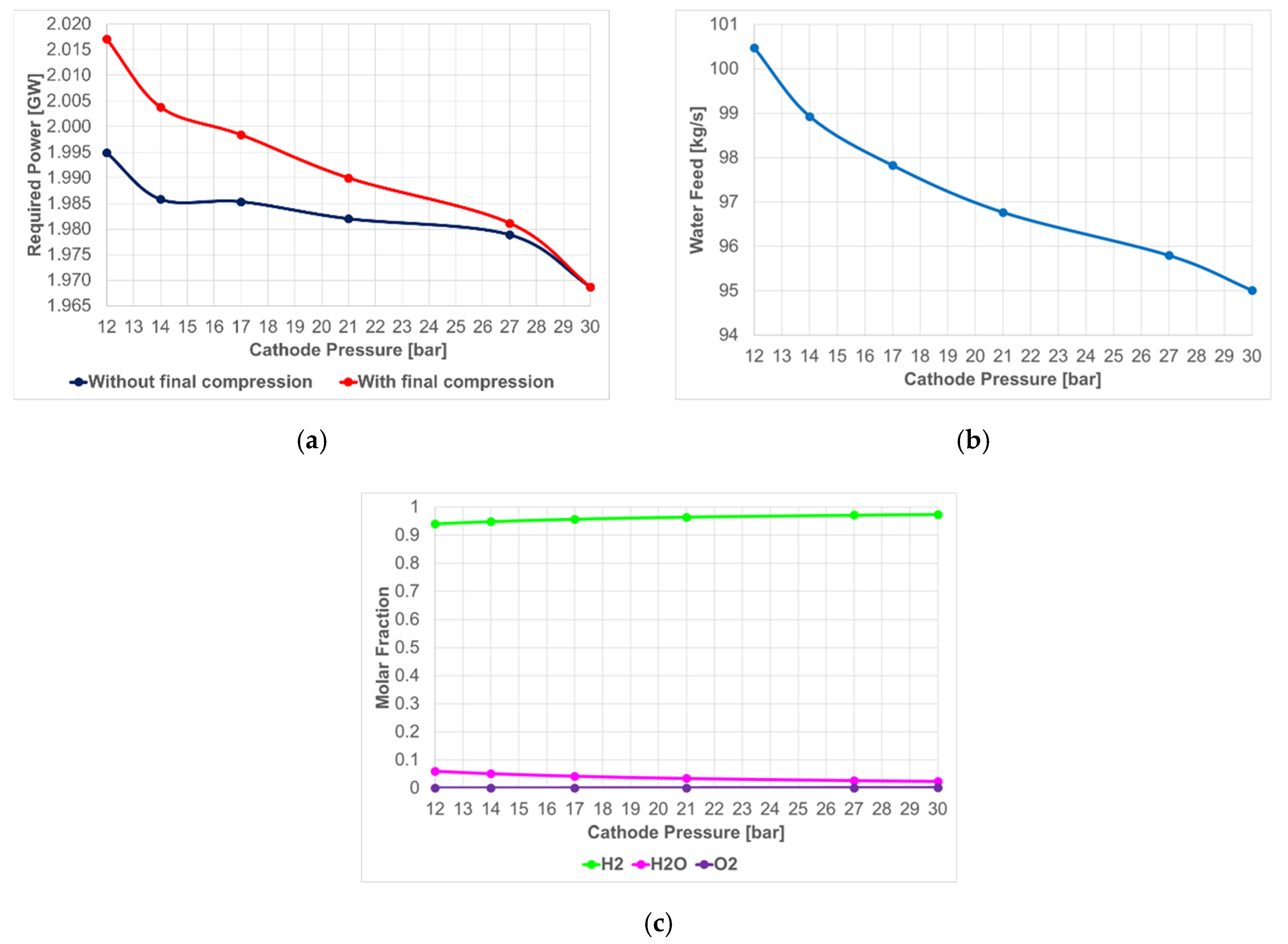
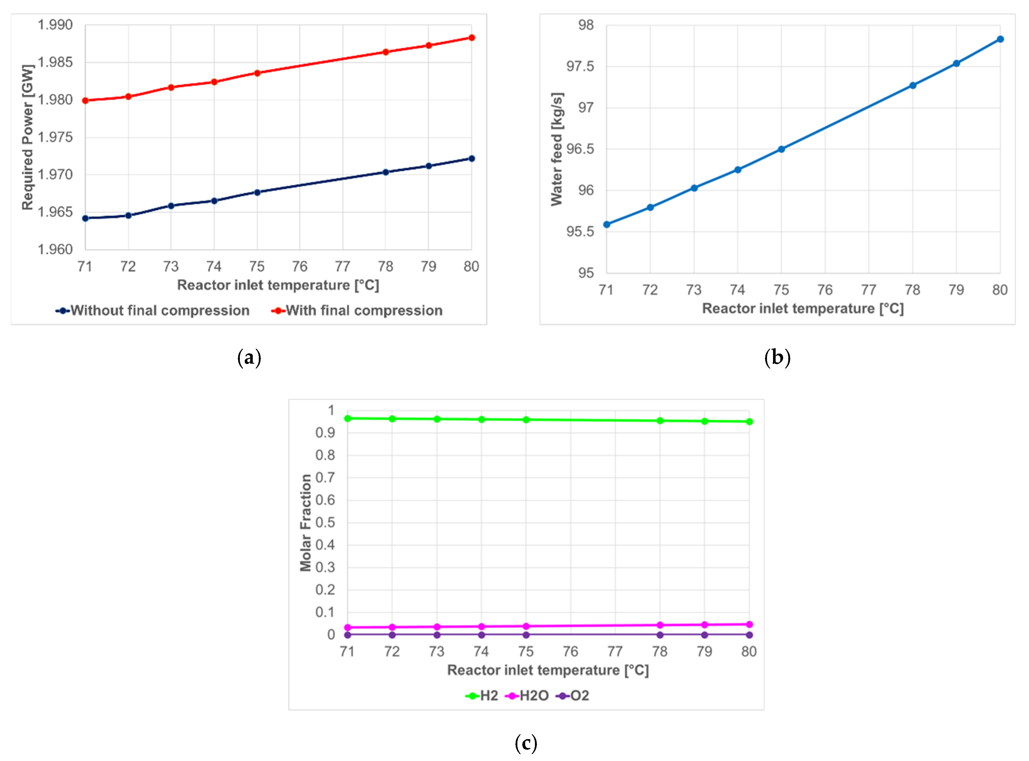
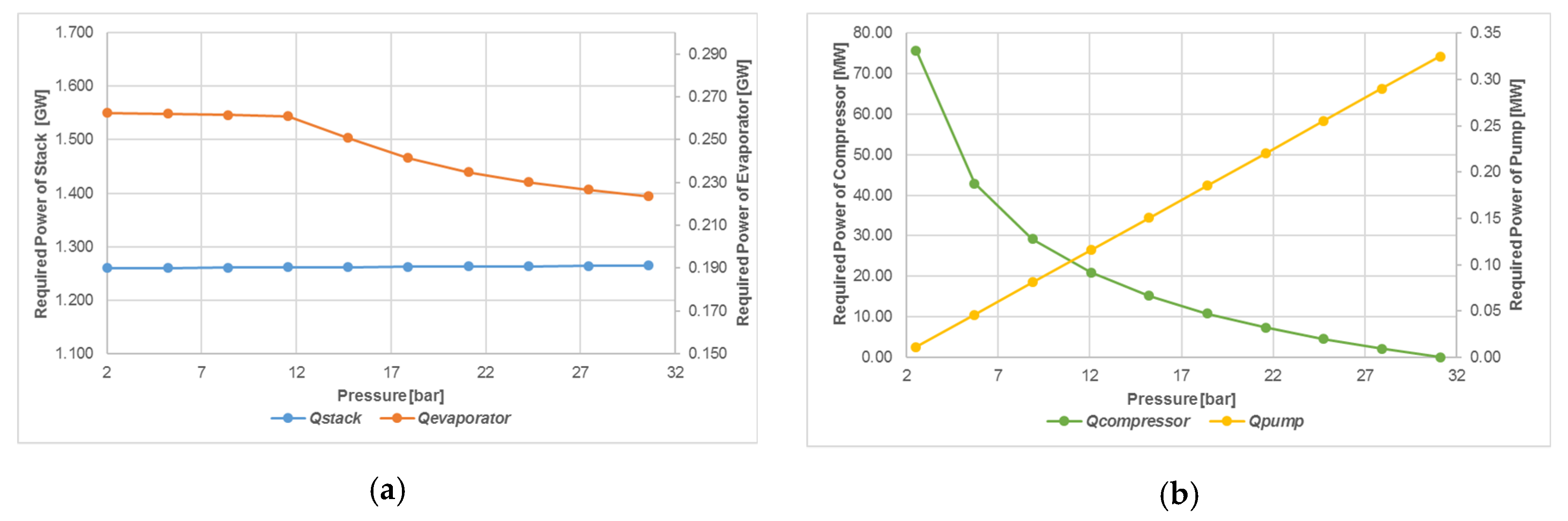
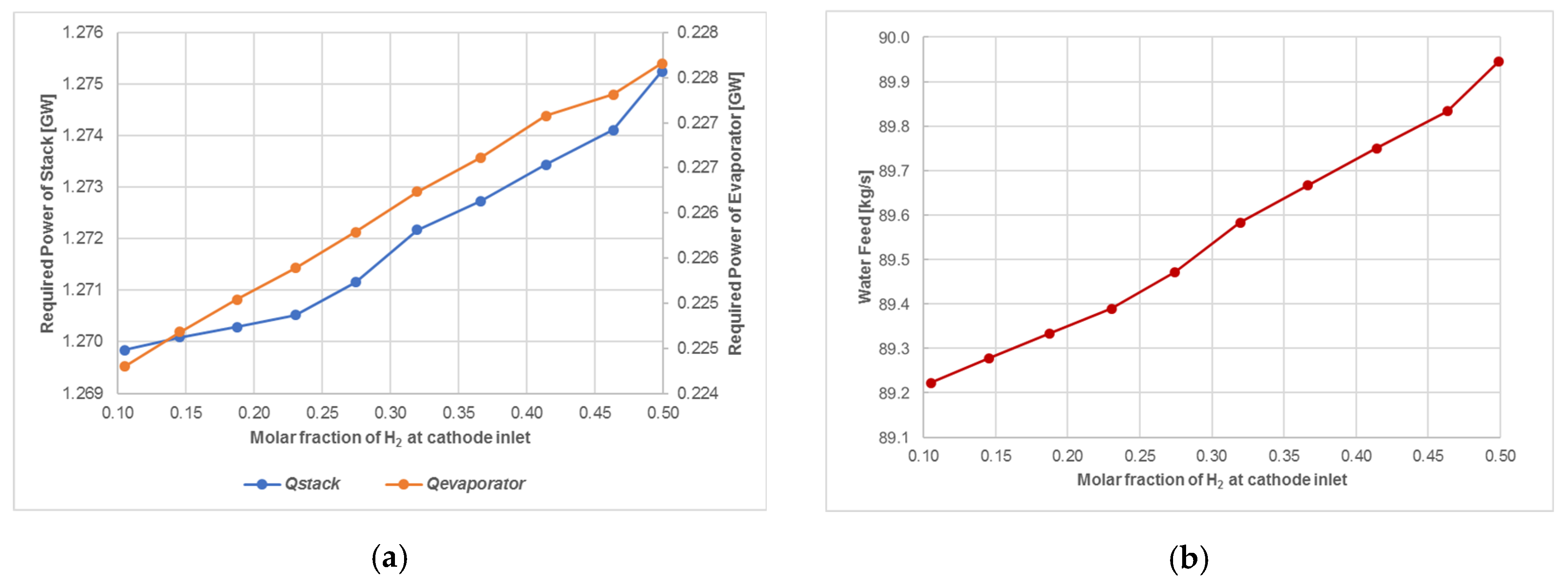
4.1.1. PEM Electrolysis

In the PEM electrolysis model, the operating pressure and temperature have been changed and the following variables have been monitored:
  • Required power (before and after the final compression to obtain H2 stored at 30 bar);
  • water feed; and
  • composition of gas stream produced in the cathode section before the final purification step.
The cathode pressure is varied between 12 bar and 30 bar (anode section is always considered 10% of cathode ones) and the results are shown in Figure 7.
The increasing of pressure leads to a decrease of the required power and water feed. In particular, if there is an increase of the operating pressure, energy consumption for compressing the produced hydrogen can be avoided. In addition, Figure 7c shows that the purity of hydrogen stream in the cathode section, before the last step of separation, slightly increases, despite the higher pressure difference between the two electrolyzer sections tends to rise the permeation of undesired products from cathode to anode sections and vice versa. Therefore, the increase in the efficiency of the electrolysis reaction has a preponderant influence over the undesired permeation and the last step of purification can be less efficient (and thus less expensive). Although the advantages of operating at higher pressures, it is necessary considering the materials and the units suitable for high pressure. Therefore, a compromise is required.
The effects of increasing the reactor inlet temperature between 71 °C and 80 °C, by keeping the maximum difference between inlet and outlet temperature at 10 °C, are reported in Figure 8. The increase of temperature leads to an almost linear and slight rise of the amount of required power (especially related to the water heating) and water feed. Obviously, the final compression of hydrogen increases the amount of total required power. However, the amount of power required for compression is negligibly affected by the reactor inlet temperature, such as shown by the almost constant difference between the two curves in Figure 8a. On the other hand, the composition of hydrogen stream before the last step of purification appears not considerably affected by the temperature change. It could be that the increase of the operating temperature allows a faster electrolysis but it cannot be evaluated by exploiting the developed and used stationary model.

4.1.2. SOEC Electrolysis

In SOEC Electrolysis the temperature and the pressure are the key parameters in energy requirement of the system. For this reason, the sensitivity analyses by changing the temperature between 600–1000 °C and the pressure between 1–30 bar have been carried out.
The Figure 9 shows the variation of required thermal power of stack and required thermal power of evaporator. The power of pump required for increasing the fresh water pressure up to 30 bar is constant and equal to 325.9 kW.
The increase of temperature leads to a linear increase of stack thermal power; on the other hand, the power required by the evaporator decreases because more thermal energy is recovered in the heat exchangers. The total required power (including stack, evaporator and water pump) increases from 1482 MW up to 1499 MW, with an increment of 1%. From these results, it emerges that, in terms of required power, it seems better to work at lower temperatures to reduce the required power, but according to literature this leads to a decrease in the efficiency of the stack due to the decrease of electrode activity, the increase of overpotential and polarization losses [90]; however, the developed model type cannot allow the monitoring of this aspect. Furthermore, if higher operative temperatures are reached by increasing steam temperature, the electrical energy demand in the stack is reduced in favor of the thermal energy demand that is required to reach the desired steam temperature and that replaces part of the electric energy required for the reactions to occur. This is advantageous because it offers more opportunities to recover industrial waste heat or to use alternative heat sources, such as geothermal source [91]. Therefore, it is necessary to find a compromise between energy resources, efficiency and costs (high temperatures increase the material costs). Obviously, if a heat source is available, such as geothermal source or industrial waste heat, its temperature will be a dominant factor in the choice of operative temperature of the stack and will provide some constraints for the entire system.
Figure 10 represents the effect of water feed pressure on the required power of the SOEC.
The increase of inlet water pressure has advantages in terms of required power, in fact, although the power needed for the pump increases, the benefits in the reduction of required power for hydrogen compression up to 30 bar and steam generation (evaporator) are greater. The total required power decrease from 1598 MW to 1489 MW with a reduction of 6.9%.
Another important parameter in SOEC electrolysis is the amount of hydrogen recirculated in the cathode inlet, essential to prevent the creation of oxidizing environment by pure steam at elevated temperature and to preheat the fresh inlet stream. The molar fraction of H2 at the cathode inlet has been varied between 0.1 (reference case: 10% mol of H2 and 90% mol of H2O) and 0.5 by changing the amount of recirculated hydrogen. Figure 11 shows the effect of the molar fraction of hydrogen on the required power of the SOEC and on the consumed water.
The increasing of molar fraction of H2 in the gas feeding mixture leads to an increase of required power and a reduction of the produced H2 by the electrolysis reaction with consequent slight increase of required water feed to reach the desired amount of 10 kg/s of H2. In addition, if a high amount of hydrogen is present at the cathode inlet, the reaction will not occur normally because the quantity of water for electrolysis is too little. The results of this analysis confirm the choice of operating with a low content of hydrogen in the mixture at the cathode inlet: A fraction of 10–20% mol of H2 is sufficient to avoid the oxidation of the electrode and to guarantee a sufficient preheating of the feed and an effective electrolysis reaction [63].

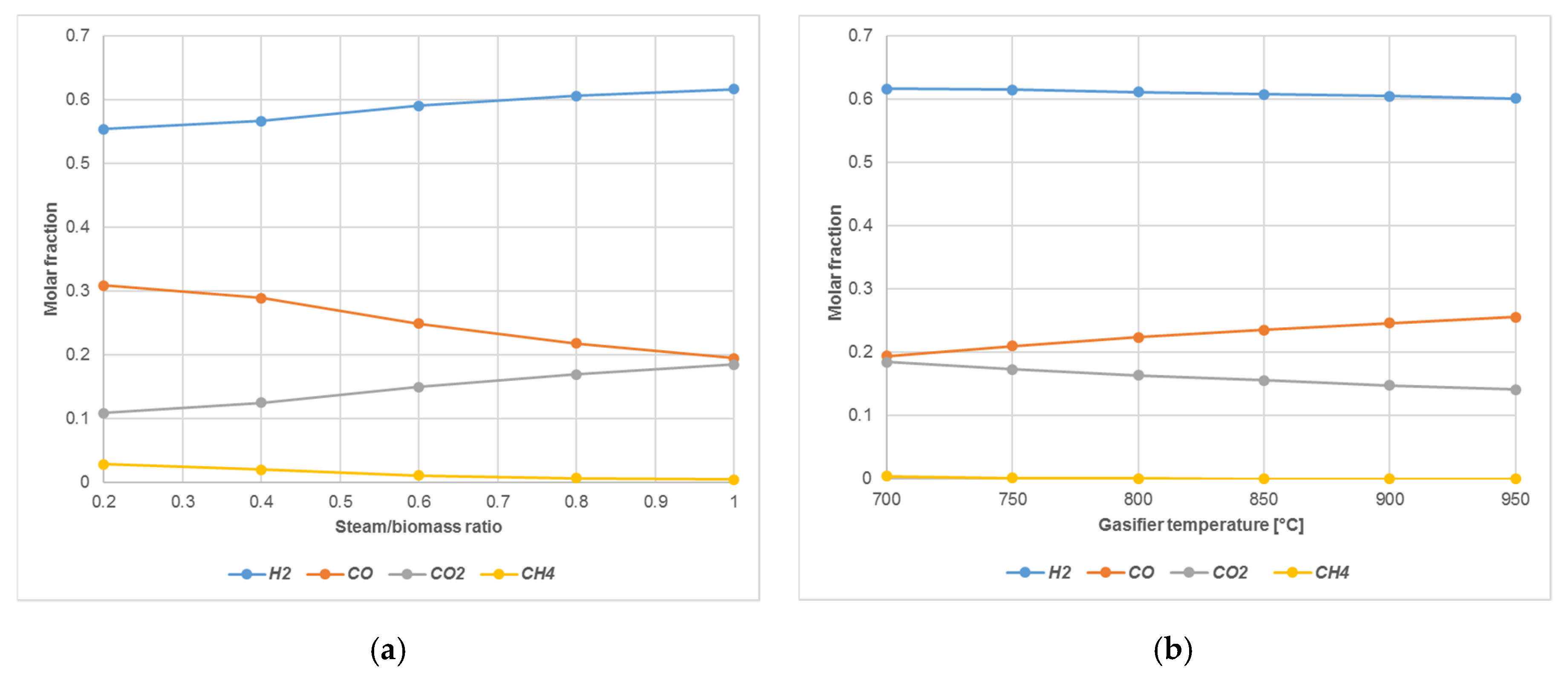
4.1.3. Biomass Gasification

In the biomass gasification the steam/biomass ratio and the temperature of gasifier are the main parameters that impact the composition of syngas. Figure 12a depicts the effect of steam/biomass ratio on composition in mole fractions of dry syngas, while Figure 12b shows how this composition is affected by the gasifier temperature.
The increase of steam/biomass ratio leads to an increase of the H2 and CO2 yields in the syngas at the expense of CO and CH4. Instead, the temperature does not significantly affect the H2 amount in the produced syngas but increases the amount of carbon monoxide with a linear behavior. Therefore, a good compromise should be achieved, according to the availability of steam, on the cost related to its production and to the separation of produced hydrogen and the reduction of carbon dioxide.

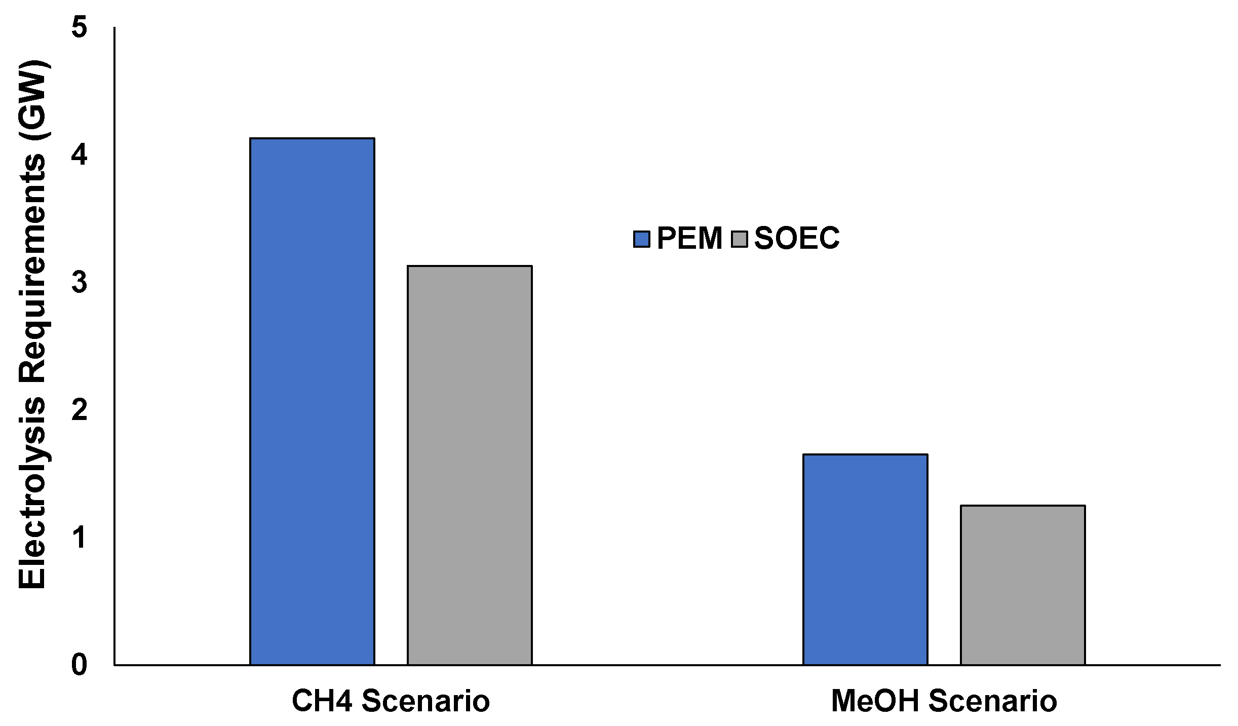
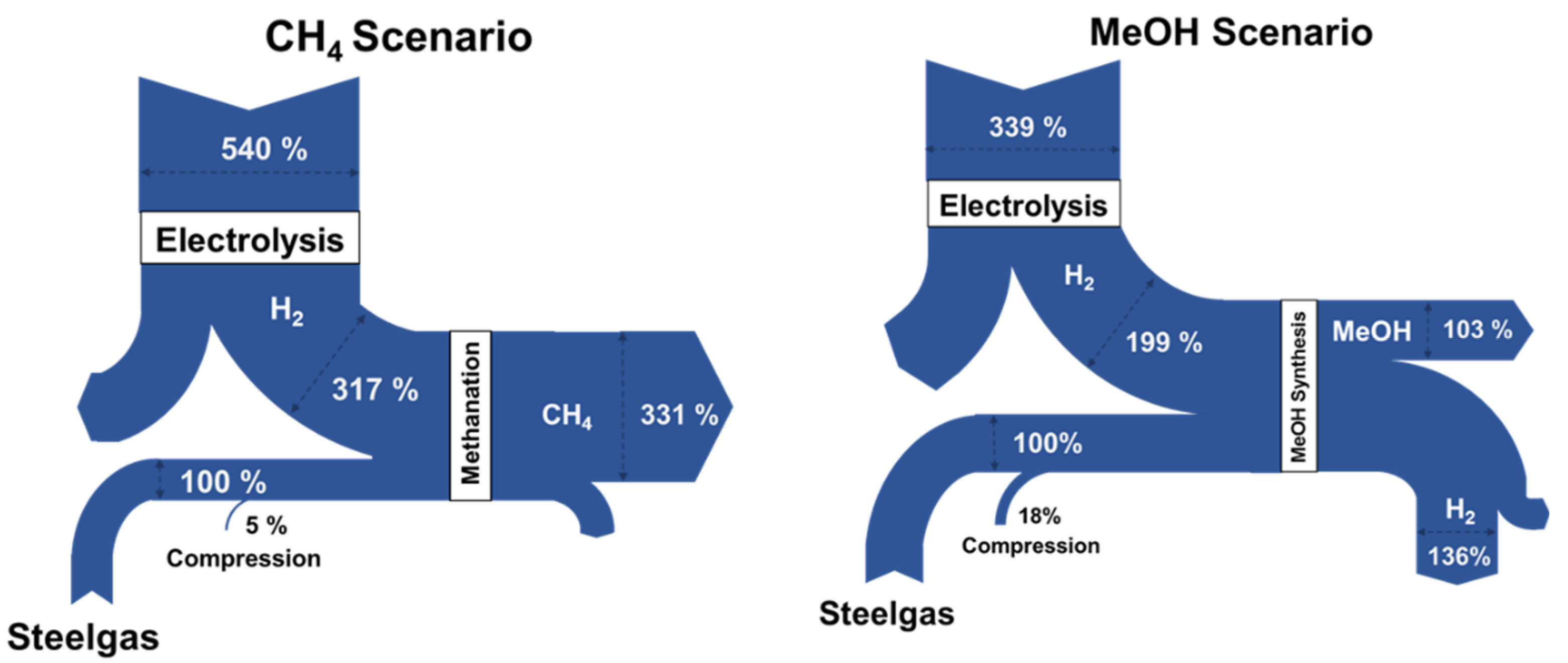
4.2. Integration of Hydrogen in Methanol and Methane Synthesis

Hydrogen intensified methane and methanol syntheses in the steel industry has been studied by coupling the hydrogen models with methane and methanol production ones by considering two base scenarios. A medium size integrated steelmaking facility with an annual steel production capacity of about 6 Mt of steel was considered.
In particular, the CH4 scenario and the MeOH scenario are defined as follows:
  • CH4 scenario: 100% exploitation of by-product gases produced in an integrated steelmaking plant for generation of methane: In this scenario the entire available amount of off-gases is used to produce methane (assuming that the vast natural gas market and transporting infrastructure can uptake easily such production). The renewable hydrogen produced either by PEM or SOEC is inserted in basic stoichiometric ratio to produce methane.
  • MeOH scenario: Methanol synthesis of a fraction of the by-product gases (~65%) due to the fact that MeOH is a product that has a limited market compared to the natural gas market and infrastructure. Again, the production of H2 is assumed to be coming from either PEM or SOEC.
Table 7 presents the results of the AspenPlus® simulations of the two scenarios focused on the hydrogen requirements and consumption, electrolysis demands, product yields, and carbon conversion.
Considering the high amount of required hydrogen for enriching the steelworks off-gases, the study shows that the use of electrolyses-based production process is preferred to the biomass-based ones. Apart from the purity of the obtainable H2, the electrolysis processes do not affect the steelworks carbon footprint if they use renewable energies than the biomass process. However, the energy content and cost of the required hydrogen used exceed the energy off-set of the steelwork plants.
In Figure 13 the PEM and SOEC electrolysis requirements are represented in the range of GWs. It is evident that both the cases are restrictive for employment in full-scale, considering also that the capacities of current available biggest commercial electrolyzers are about two order of magnitude lower.
Starting from the results of the two simulated scenarios and converting each material streams in energy content, Figure 14 reports Sankey diagrams which allow comparing the energy content of the feedstock and the electrolysis requirements (in case of PEM use) for the two scenarios. In the CH4 scenario, 540% of the energy content of the feedstock is required for PEM electrolysis, while for the MeOH scenario 339%.

5. Conclusions

Different selected renewable hydrogen production processes have been analyzed by means of AspenPlus® flowsheet simulations in order to obtain indications on the most suitable technologies for hydrogen-based enrichment of integrated steelworks off-gas to be used as feedstock in methane and methanol syntheses. In particular, PEM electrolysis, SOEC electrolysis and biomass gasification have been examined. Simulations and sensitivity analyses have been carried out in order to examine the advantages and drawbacks of the considered technologies and operating conditions, especially in terms of purity of produced hydrogen, consumed energy and water and thermodynamic efficiency, by taking into account that their application requires the coupling with renewable energy sources (in the case of electrolysis) and with the synthesis processes of methane and methanol starting from steelworks off-gases. The study shows that the use of electrolyses-based production process is preferred to the biomass-based ones: Biomass gasification appears less suitable for enrichment of steelworks gases, as less pure hydrogen is obtained with considerable production of CO2.
The study highlighted that the change in operating condition can lead to improvement of the performances: For instance, higher operating pressure leads to decrease of global amount of required energy in PEM and in SOEC systems and, in the case of PEM electrolysis, it leads to a less water consumption and to a purer hydrogen stream before the final purification stage that thus can be less efficient and with less economic impact. The sensitivity analysis also demonstrates that temperature is a key parameter in SOEC design: Its increase leads to an increase of total required power, but working at lower temperature leads to a decrease in the efficiency of the stack. Furthermore, higher operative temperature reduces the electrical energy demand in favor of the thermal energy demand. In terms of energy and water consumption SOEC technology seems to be more efficient than PEM. However, PEM shows the advantage of being more stable in case of fluctuations of power supply (as due to green power) and to be carried out with lower temperatures (the pressure is similar) and, consequently, less issues related to the equipment or corrosion issues related to the use of hot steam. On the other hand, SOEC electrolysis appears attractive if a high temperature heat source is available and if a considerable amount of industrial waste heat can be recovered.
The two analyzed scenarios for methane and methanol syntheses from off-gases of medium capacity steelworks show the importance of hydrogen and how it represents the greater energy costs in the overall process. Therefore, future works should focus on the recycling and reuse of any residual hydrogen from the synthesis processes in order to have a significant reduction in the electrolysis requirements, by making the process sustainable within the integrated steelworks in terms of both environmental and economic impacts. In addition, considering that the capacity of currently available commercial electrolyzers are not suitable to meet the required hydrogen demand, the design of novel electrolyzers or the assembly of multiple electrolyzers should be investigated in order to obtain a suitable hydrogen production by also exploiting the advantages of the scale economy.
For these reasons, an accurate economic analysis is under development in order to evaluate the full scale feasibility considering the already analyzed scenarios and furthermore specific ones (e.g., with reuse of residual hydrogen) for the implementation in real industrial contest. Concrete business case studies will be analyzed taking into account the volatility of energy green markets and the application of a dispatch controller. Indeed, the results of the simulations represent the basis for further work about the implementation of innovative advanced control system, namely dispatch controller, that will manage and will optimize the use and distribution of steelworks off-gases and H2 from volatile power sources in the methane and methanol syntheses. Also, the optimization of OPEX related to H2 intensified methane and methanol syntheses by using steelworks off-gases will start by considering the results of this work.

Author Contributions

Conceptualization, I.M., K.P., M.B., and V.C.; methodology, I.M., K.P., M.B., and V.C.; software, I.M., A.Z., A.P., S.D., and V.I.; validation I.M., V.C., and T.A.B.; formal analysis, I.M. and V.C.; investigation, A.Z., A.P., I.M., T.A.B., S.D., V.I., and V.C.; resources, V.C.; data curation, A.Z., A.P.; writing—original draft preparation, A.Z. and A.P.; writing—review and editing, V.C., I.M., T.A.B., K.P., M.B., S.D., and V.I.; visualization, A.Z. and A.P.; supervision, V.C. and I.M.; project administration, V.C.; funding acquisition, V.C. All authors have read and agreed to the published version of the manuscript.

Funding

This research was funded by the European Union through the Research Fund for Coal and Steel (RFCS), Grant Agreement No 800659.

Acknowledgments

The work described in this paper was developed within the project entitled “Integrated and intelligent upgrade of carbon sources through hydrogen addition for the steel industry”, i3upgrade) (i3upgrade, GA No. 800659), which has received funding from the Research Fund for Coal and Steel of the European Union. The sole responsibility of the issues treated in this paper lies with the authors; the Commission is not responsible for any use that may be made of the information contained therein.

Conflicts of Interest

The authors declare no conflict of interest.

References

  1. Sohn, H. Energy Consumption and CO2 Emissions in Ironmaking and Development of a Novel Flash Technology. Metals 2020, 10, 54. [Google Scholar] [CrossRef] [Green Version]
  2. Development Organisation for Economic Co-Operation (OECD). Energy Efficiency in the Steel Sector: Why It Works Well, But Not Always. 2015. Available online: http://www.oecd.org/sti/ind/Energy-efficiency-steel-sector-1.pdf (accessed on 28 September 2020).
  3. Baumert, K.; Herzog, T.; Pershing, J. Navigating the Numbers: Greenhouse Gas Data and International Climate Policy. World Resources Institute Report Washington 2005. Available online: www.oecd.org/dataoecd/28/43/36448807.pdf (accessed on 28 July 2020).
  4. Worldsteel. Steel’s Contribution to a Low Carbon Future: Worldsteel Position Paper. Available online: https://www.worldsteel.org/en/dam/jcr:7ec64bc1-c51c-439b-84b8-94496686b8c6/Position_paper_climate_2020_vfinal.pdf (accessed on 19 June 2020).
  5. Worldsteel Association. Fact Sheet: Energy Use in the Steel Industry. Available online: https://www.worldsteel.org/en/dam/jcr:f07b864c-908e-4229-9f92-669f1c3abf4c/fact_energy_2019.pdf (accessed on 19 June 2020).
  6. International Energy Agency. Energy Technologies Perspective 2017: Catalysing Energy Technology Transformations. Available online: https://0-www-oecd--ilibrary-org.brum.beds.ac.uk/energy/energy-technology-perspectives-2017_energy_tech-2017-en (accessed on 19 June 2020).
  7. Worldsteel Association. Energy Use in the Steel Industry Report Available Now. Available online: https://www.worldsteel.org/media-centre/press-releases/2015/energy-use-in-the-steel-industry-report-available-now.html (accessed on 22 June 2020).
  8. American Iron and Steel Institute. A New Roadmap for Transformation of Steelmaking Processes. Saving One Barrel of Oil Per Ton [SOBOT]. Available online: https://steel.org/~/media/Files/AISI/Public%20Policy/saving_one_barrel_oil_per_ton.pdf (accessed on 22 June 2020).
  9. Ki-Hoon, L. Drivers and Barriers to Energy Efficiency Management for Sustainable Development. Sustain. Dev. 2014, 23, 16–25. [Google Scholar]
  10. United Nation. Paris Agreement 2015. Available online: https://unfccc.int/files/essential_background/convention/application/pdf/english_paris_agreement.pdf (accessed on 22 June 2020).
  11. Matino, I.; Colla, V.; Romaniello, L.; Rosito, F.; Portulano, L. Simulation Techniques for an Efficient Use of Resources: An Overview for the Steelmaking Field. In Proceedings of the World Congress on Sustainable Technologies, London, UK, 14–16 December 2015. [Google Scholar]
  12. Matino, I.; Colla, V.; Colucci, V.; Lamia, P.; Baragiola, S.; Cecca, C.D. Improving Sustainability of Electric Steelworks through Process Simulations. CEt 2016, 52, 763–768. [Google Scholar]
  13. Florens, F.; Rübbelke, D.; Vögele, S. An analysis of the economic determinants of energy efficiency in the European iron and steel industry. J. Clean. Prod. 2015, 104, 250–263. [Google Scholar]
  14. Branca, T.; Colla, V.; Algermissen, D.; Granbom, H.; Martini, U.; Morillon, A.; Pietruck, R.; Rosendahl, S. Reuse and Recycling of By-Products in the Steel Sector: Recent Achievements Paving the Way to Circular Economy and Industrial Symbiosis in Europe. Metals 2020, 10, 345. [Google Scholar] [CrossRef] [Green Version]
  15. Conejo, A.; Birat, J.-P.; Dutta, A. A review of the current environmental challenges of the steel industry and its value chain. J. Environ. Manag. 2020, 259, 109782. [Google Scholar] [CrossRef]
  16. Remus, R.; Aguado-Monsonet, M.; Roudier, S.; Delgado-Sancho, L. Best Available Techniques (BAT) Reference Document for Iron and Steel Production. Industrial Emissions Directive 2010/75/EU (Integrated Pollution Prevention and Control). 2013. Available online: http://publications.jrc.ec.europa.eu/repository/bitstream/JRC69967/lfna25521enn.pdf (accessed on 30 September 2020).
  17. Matino, I.; Dettori, S.; Colla, V.; Weber, V.; Salame, S. Forecasting blast furnace gas production and demand through echo state neural network-based models: Pave the way to off-gas optimized management. Appl. Energy 2019, 253, 113578. [Google Scholar] [CrossRef]
  18. Maddaloni, A.; Matino, R.; Matino, I.; Dettori, S.; Zaccara, A.; Colla, V. A Quadratic Programming Model for the Optimization of Off-Gas Network in Integrated Steelworks. Matériaux Tech. 2020, 107, 5. [Google Scholar] [CrossRef]
  19. Porzio, G.; Fornai, B.; Amato, A.; Matarese, N.; Vannucci, M.; Chiappelli, L.; Colla, V. Reducing the energy consumption and CO2 emissions of energy intensive industries through decision support systems - An example of application to the steel industry. Appl. Energy 2013, 112, 818–833. [Google Scholar] [CrossRef]
  20. Maddaloni, A.; Porzio, G.; Nastasi, G.; Colla, V.; Branca, T. Multi-objective optimization applied to retrofit analysis: A case study for the iron and steel industry. Appl. Therm. Eng. 2015, 91, 638–646. [Google Scholar] [CrossRef]
  21. Zhao, X.; Bai, H.; Lu, X.; Shi, Q.; Han, J. A MILP model concerning the optimisation of penalty factors for the short-term distribution of byproduct gases produced in the iron and steel making process. Appl. Energy 2015, 148, 142–158. [Google Scholar] [CrossRef]
  22. Kong, H.; Qi, E.; Li, H.; Li, G.; Zhang, X. A MILP model for optimization of by-product gases in the integrated iron and steel plant. Appl. Energy 2009, 87, 2156–2163. [Google Scholar] [CrossRef]
  23. Porzio, G.; Nastasi, G.; Colla, V.; Vannucci, M.; Branca, T. Comparison of multi-objective optimization techniques applied to off-gas management within an integrated steelwork. Appl. Energy 2014, 136, 1085–1097. [Google Scholar] [CrossRef]
  24. de Oliveira Junior, V.B.; Pena, J.C.; Salles, J.F. An improved plant-wide multiperiod optimization model of a byproduct gas supply system in the iron and steel-making process. Appl. Energy 2016, 164, 462–474. [Google Scholar] [CrossRef]
  25. Colla, V.; Matino, I.; Dettori, S.; Petrucciani, A.; Zaccara, A.; Weber, V. Assessing the efficiency of the off-gas network management in integrated steelworks. Mater. Tech. 2019, 107, 104. [Google Scholar] [CrossRef]
  26. Maruoka, N.; Akiyama, T. Exergy recovery from steelmaking off-gas by latent heat storage for methanol production. Energy 2006, 31, 1632–1642. [Google Scholar] [CrossRef]
  27. Uribe-Soto, W.; Portha, J.; Commenge, J.; Falk, L. A review of thermochemical processes and technologies to use steelworks off-gases. Renew. Sustain. Energy Rev. 2017, 74, 809–823. [Google Scholar] [CrossRef]
  28. Dreillarda, M.; Broutina, P.; Huarda, T.; Lettat, A. Application of the DMXTM CO2 Capture Process in Steel Industry. Energy Procedia 2017, 114, 2573–2589. [Google Scholar] [CrossRef]
  29. Deerberg, G.; Oles, M.; Schlögl, R. The Project Carbon2Chem®. Chem. Ing. Tech. 2018, 90, 1365–1368. [Google Scholar] [CrossRef]
  30. Mission Innovation Austria. Austria’s Way into the Future of Energy: Strategies and Success Stories. 2019. Available online: http://mission-innovation.net/wp-content/uploads/2019/05/MI-Austrias-Way-Into-the-Future-of-Energy-May-2019.pdf (accessed on 30 September 2020).
  31. Kim, D.; Han, J. Techno-economic and climate impact analysis of carbon utilization process for methanol production from blast furnace gas over Cu/ZnO/Al2O3 catalyst. Energy 2020, 198, 117355. [Google Scholar] [CrossRef]
  32. Gao, R.; Zhang, C.; Kwakc, G.; Lee, Y.-J.; Kang, S.C.; Guan, G. Techno-economic evaluation of methanol production using by-product gases from iron and steel works. Energy Convers. Manag. 2020, 213, 112819. [Google Scholar] [CrossRef]
  33. Shin, S.; Lee, J.-K.; Lee, I.-B. Development and techno-economic study of methanol production from coke-oven gas blended with Linz Donawitz gas. Energy 2020, 200, 117506. [Google Scholar] [CrossRef]
  34. Nikolaidis, P.; Poullikkas, A. A comparative overview of hydrogen production processes. Renew. Sustain. Energy Rev. 2017, 67, 597–611. [Google Scholar] [CrossRef]
  35. Hajjaji, N.; Pons, M.-N.; Houas, A.; Renaudin, V. Exergy analysis: An efficient tool for understanding and improving hydrogen production via the steam methane reforming process. Energy Policy 2012, 42, 392–399. [Google Scholar] [CrossRef]
  36. Acar, C.; Dincer, I. Comparative assessment of hydrogen production methods from renewable and non-renewable sources. Int. J. Hydrogen Energy 2014, 39, 1–12. [Google Scholar] [CrossRef]
  37. Dincer, I.; Acar, C. Review and evaluation of hydrogen production methods for better sustainability. Int. J. Hydrogen Energy 2015, 40, 11094–11111. [Google Scholar] [CrossRef]
  38. Joshi, A.S.; Dincer, I.; Reddy, B.V. Solar hydrogen production: A comparative performance assessment. Int. J. Hydrogen Energy 2011, 36, 1124–1257. [Google Scholar] [CrossRef]
  39. Khosravi, A.; Koury, R.; Machado, L.; Pabon, J. Energy, exergy and economic analysis of a hybrid renewable energy with hydrogen storage system. Energy 2018, 148, 1087–1102. [Google Scholar] [CrossRef]
  40. Bicakova, O.; Straka, P. Production of hydrogen from renewable resources and its effectiveness. Int. J. Hydrogen Energy 2012, 37, 1156–11578. [Google Scholar] [CrossRef]
  41. Ozbilen, A.; Dincer, I.; Rosen, M.A. Comparative environmental impact and efficiency assessment of selected hydrogen production methods. Environ. Impact Assess. Rev. 2013, 42, 1–9. [Google Scholar] [CrossRef]
  42. Azwar, M.; Hussain, M.; Abdul-Wahab, A. Development of biohydrogen production by photobiological, fermentation and electrochemical processes: A review. Renew. Sustain. Energy Rev. 2014, 31, 158–173. [Google Scholar] [CrossRef]
  43. Balat, H.; Kirtay, E. Hydrogen from biomass—Present scenario and future prospects. Int. J. Hydrogen Energy 2010, 35, 7416–7426. [Google Scholar] [CrossRef]
  44. Kotay, S.M.; Das, D. Biohydrogen as a renewable energy Resource-Prospects and potentials. Int. J. Hydrogen Energy 2008, 33, 258–263. [Google Scholar]
  45. Cai, Q.; Luna-Ortiz, E.; Adjiman, C.S.; Brandon, N.P. The Effects of Operating Conditions on the Performance of a Solid Oxide Steam Electrolyser: A Moldel-Based Study. Fuel Cells 2010, 10, 1114–1128. [Google Scholar] [CrossRef]
  46. Amikam, G.; Nativ, P.; Gendel, Y. Chlorine-free alkaline seawater electrolysis for hydrogen production. Int. J. Hydrogen Energy 2018, 43, 6504–6514. [Google Scholar] [CrossRef]
  47. Sellamia, M.; Loudiyi, K. Electrolytes behaviour during hydrogen production by solar energy. Renew. Sustain. Energy Rev. 2017, 70, 1331–1335. [Google Scholar] [CrossRef]
  48. Chakik, F.E.; Kaddami, M.; Mikou, M. Effect of operating parameters on hydrogen production by electrolysis of water. Int. J. Hydrogen Energy 2017, 42, 25550–25557. [Google Scholar] [CrossRef]
  49. Zeng, K.; Zhang, D. Recent progress in alkaline water electrolysis for hydrogen production and applications. Prog. Energy Combust. Sci. 2010, 36, 307–326. [Google Scholar] [CrossRef]
  50. Bhandari, R.; Trudewind, C.A.; Zapp, P. Life Cycle Assessment of Hydrogen Production via Electrolysis – A review. J. Clean. Prod. 2013, 85, 151–163. [Google Scholar] [CrossRef]
  51. Vincent, I.; Bessarabov, D. Low cost hydrogen production by anion exchange membrane electrolysis: A review. Renew. Sustain. Energy Rev. 2018, 81, 1690–1704. [Google Scholar] [CrossRef]
  52. de Araujo, F.H.M.; Braga, L.B.; Colombaroli, T.S.; Pedroso, D.T.; da Silva, M.E.; Silveira, J.; Tapia, L.C.F.; Tuna, C.E.; Vane, L.F.; Vigouroux, R.Z. Sustainable Hydrogen Production Processes, 1st ed.; José, L.S., Ed.; Springer: Sao Paolo, Brazil, 2017. [Google Scholar]
  53. Ursua, A.; Gandia, L.M.; Sanchis, P. Hydrogen Production from Water Electrolysis: Current Status and Future Trends. Proc. IEEE 2011, 100, 410–426. [Google Scholar] [CrossRef]
  54. Ferrero, D.; Lanzini, A.; Santarelli, M.; Leone, P. A comparative assessment on hydrogen production from low- and high-temperature electrolysis. Int. J. Hydrogen Energy 2013, 38, 3523–3536. [Google Scholar] [CrossRef]
  55. Mehmeti, A.; Angelis-Dimakis, A.; Arampatzis, G.S.; McPhail, J.; Ulgiati, S. Life Cycle Assessment and Water Footprint of Hydrogen Production Methods: From Conventional to Emerging Technologies. Enviroments 2018, 5, 24. [Google Scholar] [CrossRef] [Green Version]
  56. Medina, P.; Santarelli, M. Analysis of water transport in a high pressure PEM electrolyzer. Int. J. Hydrogen Energy 2010, 35, 5173–5186. [Google Scholar] [CrossRef]
  57. Barbir, F. PEM electrolysis for production of hydrogen from renewable energy sources. J. Sol. Energy 2005, 78, 661–669. [Google Scholar] [CrossRef]
  58. The World’s Most Efficient and Reliable Electrolyser. Available online: www.nelhydrogen.com (accessed on 15 July 2020).
  59. Hydrogen Generation HyLYZER® PEM Electrolysis Technology. Available online: www.hydrogenics.com (accessed on 26 May 2020).
  60. Profit Generators. HOGEN® On-Site Hydrogen Generation Systems. Available online: www.linde-gas.com (accessed on 26 May 2020).
  61. PEMELECTROLYSERS: Today’s Flexible&Cost Effective Technology. Available online: www.arevah2gen.com (accessed on 26 May 2020).
  62. Im-orb, K.; Visitdumrongkul, N.; Seabea, D.; Patcharavorachot, Y.; Arpornwichanop, A. Flowsheet-based model and exergy analysis of solid oxide electrolysis cells for clean hydrogen production. J. Clean. Prod. 2018, 170, 1–13. [Google Scholar] [CrossRef]
  63. KOH, J.; YOON, D.; OH, C.H. Simple Electrolyzer Model Development for High-Temperature Electrolysis System Analysis Using Solid Oxide Electrolysis Cell. J. Nucl. Sci. Technol. 2010, 47, 599–607. [Google Scholar] [CrossRef]
  64. Rivera-Tinoco, R.; Farran, M.; Bouallou, C.; Aupretre, F.; Valentin, S.; Millet, P.; Ngameni, J. Investigation of power-to-methanol processes coupling electrolytic hydrogen production and catalytic CO2 reduction. Int. J. Hydrogen Energy 2016, 41, 4546–4559. [Google Scholar] [CrossRef]
  65. Bridgwater, A.V. Review of fast pyrolysis of biomass and product upgrading. Biomass Bioenergy 2012, 38, 68–94. [Google Scholar] [CrossRef]
  66. Hydrogen Production: Biomass Gasification. Available online: https://www.energy.gov/eere/fuelcells/hydrogen-production-biomass-gasification (accessed on 26 July 2020).
  67. Parthasarathy, P.; Narayanan, K.S. Hydrogen production from steam gasification of biomass: Influence of process parameters on hydrogen yield—A review. J. Renew. Energy 2014, 66, 570–579. [Google Scholar] [CrossRef]
  68. Neubert, M.; Hauser, A.; Pourhossein, B.; Dillig, M.; Karl, J. Experimental evaluation of a heat pipe cooled structured reactor as part of a two-stage catalytic methanation process in power-to-gas applications. Appl. Energy 2018, 229, 289–298. [Google Scholar] [CrossRef]
  69. Leimert, J.M.; Neubert, M.; Treiber, P.; Dillig, M.; Karl, J. Combining the Heatpipe Reformer technology with hydrogen-intensified methanation for production of synthetic natural gas. Appl. Energy 2018, 217, 37–46. [Google Scholar] [CrossRef]
  70. Schildhauer, T.J.; Biollaz, S.M.A. Synthetic Natural Gas from Coal and Dry Biomass, 1st ed.; John Wiley & Sons: Hoboken, NJ, USA, 2016. [Google Scholar]
  71. Koytsoumpa, E.I.; Karellas, S.; Kakaras, E. Modelling of Substitute Natural Gas production via combined gasification and power to fuel. J. Renew. Energy 2019, 135, 1354–1370. [Google Scholar] [CrossRef]
  72. Thema, M.; Weidlich, T.; Hörl, M.; Bellack, A.; Mörs, F.; Hackl, M.K.F.; Gleich, J.; Stabenau, C.; Huber, H.; Hafenbradl, D.; et al. Biological CO2-Methanation: An Approach to Standardization. Energies 2019, 12, 1670. [Google Scholar] [CrossRef] [Green Version]
  73. Razzaq, R.; Li, C.; Zhang, S. Coke oven gas: Availability, properties, purification, and utilization in China. Fuel 2013, 113, 287–299. [Google Scholar] [CrossRef]
  74. Bozzano, G.; Manenti, F. Efficient methanol synthesis: Perspectives, technologies and optimization strategies. Prog. Energy Combust. Sci. 2016, 56, 71–105. [Google Scholar] [CrossRef]
  75. Schittkowski, J.; Ruland, H.; Laudenschleger, D.; Girod, K.; Kahler, K.; Kaluza, S.; Muhler, M.; Schlogl, R. Methanol Synthesis from Steel Mill Exhaust Gases: Challenges for the Industrial Cu/ZnO/Al2O3 Catalyst. Chem. Ing. Tech. 2018, 90, 1419–1429. [Google Scholar] [CrossRef] [Green Version]
  76. Graaf, G.H.; Winkelman, J.G.M.; Stamhuis, E.J.; Beenackers, A.A.C.M. Kinetics of the three phase methanol synthesis. Chem. Eng. Sci. 1988, 43, 2161–2168. [Google Scholar] [CrossRef]
  77. Smolinka, T.; Gunther, M.; Garche, J. NOW-Studie: Stand und Entwicklungspotenzial der Wasserelektrolyse zur Herstellung von Wasserstoff aus Regenerativen Energien; Technical Report; Fraunhofer ISE: Freiburg, Germany, 2011. [Google Scholar]
  78. PEM Electrolyzer Types. Available online: https://ntrs.nasa.gov/search.jsp?R=20170009573 (accessed on 26 July 2020).
  79. Houaijia, A.; Breuer, S.; Thomey, D.; Brosig, C.; Säck, J.P.; Roeb, M.; Sattler, C. Solar Hydrogen by High-temperature Electrolysis: Flowsheeting and Experimental Analysis of a Tube-type Receiver Concept for Superheated Steam Production. Energy Procedia 2014, 49, 1960–1969. [Google Scholar] [CrossRef] [Green Version]
  80. Ioraa, P.; Chiesa, P. High efficiency process for the production of pure oxygen based on solid oxide fuel cell–solid oxide electrolyzer technology. J. Power Sources 2009, 190, 408–416. [Google Scholar] [CrossRef]
  81. Henke, M.; Hillius, S.; Riedel, M.; Kallo, J.; Friedrich, K.A. Gas recirculation at the hydrogen electrode of solid oxide fuel cell and solid oxide electrolysis cell systems. Fuel Cells 2016, 16, 584–590. [Google Scholar] [CrossRef]
  82. Bernadet, L.; Moncasi, C.; Torrell, M.; Tarancón, A. High-performing electrolyte-supported symmetrical solid oxide electrolysis cells operating under steam electrolysis and co-electrolysis modes. Int. J. Hydrogen Energy 2020, 45, 14208–14217. [Google Scholar] [CrossRef]
  83. Udagawa, J.; Aguiar, P.; Brandon, N. Hydrogen production through steam electrolysis: Control strategies for a cathode-supported intermediate temperature solid oxide electrolysis cell. J. Power Sources 2018, 180, 354–364. [Google Scholar] [CrossRef]
  84. Pala, L.P.R.; Wang, Q.; Kolb, G.; Hessel, V. Steam gasification of biomass with subsequent syngas adjustment using shift reaction for syngas production: An Aspen Plus model. J. Renew. Energy 2017, 101, 484–492. [Google Scholar] [CrossRef]
  85. Doherty, W.; Reynolds, A.; Kennedy, D. Aspen Plus Simulation of Biomass Gasification in a Steam Blown Dual Fluidised Bed. In Materials and Processes for Energy: Communicating Current Research and Technological Developments; Méndez-Vilas, A., Ed.; Formatex Research Centre: Badajoz, Spain, 2013. [Google Scholar]
  86. Begum, S.; Rasul, M.; Akbar, D.; Ramzan, N. Performance Analysis of an Integrated Fixed Bed Gasifier Model for Different Biomass Feedstocks. Energies 2013, 6, 6508–6524. [Google Scholar] [CrossRef] [Green Version]
  87. Nikoo, M.B.; Mahinpey, N. Simulation of biomass gasification in fluidized bed reactor using ASPEN PLUS. Biomass Bioenergy 2008, 32, 1245–1254. [Google Scholar] [CrossRef]
  88. Matsui, I.; Kunii, D.; Furusawa, T. Study of Fluidized Bed Steam Gasification of Char by Thermogravimetrically Obtained Kinetics. J. Chem. Eng. Jpn. 1985, 18, 105–113. [Google Scholar] [CrossRef] [Green Version]
  89. Fremaux, S.; Beheshti, S.; Ghassemi, H.; Shahsavan-Markadeh, R. An experimental study on hydrogen-rich gas production via steam gasification of biomass in a research-scale fluidized bed. Energy Convers. Manag. 2015, 91, 427–432. [Google Scholar] [CrossRef]
  90. Mingyi, L.; Bo, Y.; Jingming, X.; Jing, C. Thermodynamic analysis of the efficiency of high-temperature steam electrolysis system for hydrogen production. J. Power Sources 2008, 177, 493–499. [Google Scholar] [CrossRef]
  91. Ni, M.; Leung, M.K.H.; Leung, D.Y.C. Energy and exergy analysis of hydrogen production by solid oxide steam electrolyzer plant. Int. J. Hydrogen Energy 2007, 32, 4648–4660. [Google Scholar] [CrossRef]
Figure 1. Hydrogen production methods [34].
Metals 10 01535 g001
Figure 2. (a) Schematic representation of polymer electrolyte membrane (PEM) electrolysis; (b) Schematic representation of solid oxide electrolyzer cell (SOEC) electrolysis.
Metals 10 01535 g002
Figure 3. Aspen Plus® flowsheet of PEM electrolysis model.
Metals 10 01535 g003
Figure 4. Aspen Plus® flowsheet of SOEC electrolysis model.
Metals 10 01535 g004
Figure 5. Aspen Plus® flowsheet of biomass gasification model.
Metals 10 01535 g005
Figure 6. Integration of hydrogen production with methanol and methane synthesis: Stream 1—feed, stream 2—H2 feed, stream 3—reactor inlet, stream 4—reactor outlet.
Metals 10 01535 g006
Figure 7. Results related to cathode operating pressure changes for 10 kg/s H2 production: (a) Total required power; (b) water feed rate; (c) molar fraction in gas flow obtained in cathode section.
Metals 10 01535 g007
Figure 8. Results related to reactor inlet temperature changes for 10 kg/s H2 production: (a) Total required power; (b) water feed rate; and (c) molar fraction in gas flow obtained in cathode section.
Metals 10 01535 g008
Figure 9. Effect of temperature change in the power requirement of stack and evaporator for 10 kg/s H2 production.
Metals 10 01535 g009
Figure 10. (a) Effect of pressure on required power for the operation of the stack and the evaporator for 10 kg/s H2 production; (b) Effect of pressure on required power of pump and compressor for 10 kg/s H2 production.
Metals 10 01535 g010
Figure 11. (a) Effect of H2 recirculation at the cathode inlet on the power requirements; (b) effect of H2 recirculation at the cathode inlet on the water feed rate (for 10 kg/s H2 production).
Metals 10 01535 g011
Figure 12. (a) Effect of steam/biomass ratio and gasifier temperature on the water free composition of the produced syngas; (b) effect of gasifier temperature on the water free composition of the produced syngas.
Metals 10 01535 g012
Figure 13. PEM and SOEC electrolysis requirements (MeOH: S.N. = 1.7, CH4: Stoichiometric).
Metals 10 01535 g013
Figure 14. Sankey diagram—energy analysis of CH4 scenario and MeOH scenario.
Metals 10 01535 g014
Table 1. Comparison between biomass gasification processes [67].
Air GasificationOxygen GasificationSteam Gasification
Product heating value (MJ/Nm3)Low, 4–6Medium, 10–15High, 15–20
ProductsCO, H2, Water, CO2, HC, Tar, N2CO, H2, HCs, CO2H2, CO, CO2, CH4, light HCs, tar
Average product gas compositionH2 15%, CO 20%, CH4 2%, CO2 15%, N2 48%H2 40%, CO 40%, CO2 20%H2 40%, CO 25%, CH4 8%, CO2 25%, N2 2%
Reactor temperature (°C)900–11001000–1400700–1200
CostLowHighMedium
Table 2. Reaction equations for the methane and methanol synthesis of CO and CO2 [69,76].
Reaction EquationReaction Enthalpy ΔH0 (kJ/mol)
Methane synthesisCO + 3H2 → CH4 + H2O−206
CO2 + 4H2 → CH4 + 2H2O−165
CO2 + H2 → CO + H2O+41
Methanol synthesisCO + 2H2 → CH3OH−90
CO2 + 3H2 → CH3OH + H2O−49
CO2 + H2 → CO + H2O+41
Table 3. Proximate analysis and ultimate analysis inserted in the model [85].
Wood Residue → Moisture 5.01 wt.%
Proximate Analysis (wt.%, dry)Ultimate Analysis (wt.%, dry)
Volatile matter81.81C50.08
Fixed carbon17.83H6.70
Ash0.36O42.51
N0.16
S0.20
Cl-
Ash0.36
Table 4. Restricted chemical equilibrium in the GASI reactor.
Reaction NumberReaction SchemeReaction NameHeat of Reaction ΔH (kJ/mol)
1C + O2 → CO2Carbon combustion−393.0
2C + 0.5 O2 → COCarbon partial oxidation−112.0
3C + CO2 → 2 COBoudouard reaction+172.0
4C + H2O → CO + H2Water gas shift reaction+131.0
5CO + H2O → CO2 + H2Water gas shift reaction−41.0
6C + 2 H2 → CH4Methanation of carbon−74.0
7H2 + 0.5 O2 → H2OHydrogen partial combustion−242.0
8CH4 + H2O → CO + 3 H2Steam reforming of methane+206.0
9H2 + S → H2SH2S formation−20.2
Table 5. Hydrogen production results based on PEM and SOEC models.
H2O Feed
(kg/s)
Required Power
(MW)
Required Energy
(kWh/kg of H2)
H2O Feed
(kg/kg of H2)
Thermodynamic Electrolyser Efficiency
(%)
PEM97.81988.954.89.862.60
SOEC89.21494.541.68.983.50
Table 6. Hydrogen production results based on biomass gasification model.
Biomass Feed
(kg/s)
Efficiency
(%)
Syngas Molar Composition
(%)
77.3912.90CO2 = 18.4
CH4 = 0.4
H2 = 61.7
CO = 19.4
Table 7. Main results of the analyzed scenarios.
CH4 ScenarioMeOH Scenario
Off-gas feed (kg/s)190.3125.3
Feed Compression (MW)38.385.4
H2 Feed (kg/s)20.98.4
H2 Consumption (%)98.437.4
CH4 Product (kg/s)50.4-
CH3OH Product (kg/s)-25.1
Carbon Conversion (%)98.638.8
CO2 Utilization (%)96.95.8
Publisher’s Note: MDPI stays neutral with regard to jurisdictional claims in published maps and institutional affiliations.

