Numerical Investigation of Blast Furnace Operation with Scrap Charging


State Key Laboratory of Advanced Metallurgy, University of Science and Technology Beijing, Beijing 100083, China
*
Author to whom correspondence should be addressed.
Metals 2020, 10(12), 1666; https://0-doi-org.brum.beds.ac.uk/10.3390/met10121666
Submission received: 17 November 2020
/
Revised: 7 December 2020
/
Accepted: 10 December 2020
/
Published: 13 December 2020
(This article belongs to the Special Issue Sustainable Steel Industry: Energy and Resource Efficiency, Low-Emissions and Carbon-Lean Production)
Abstract
:One approach to reduce CO2 emission in the steelmaking industry is to recycle scrap to the blast furnace/basic oxygen furnace (BF/BOF) production system. This paper performed a numerical investigation on the BF operation with scrap charging. The investigated BF was with an inner volume of 820 m3, producing 2950 tons of hot metal per day (tHM/d). The simulated results indicated the following: Extra scrap addition in BF causes the decrease of shaft temperature, the decrease of local gas utilization, and the lowering of cohesive zone position, leading to an unstable BF running. The partial replacement of sinter with scrap in BF can mitigate the negative effects induced by scrap charging. The optimal scrap rate in the BF is 178 kg/tHM, under which the BF reaches a productivity of 3310 tHM/d, a top-gas utilization of 48.5%, and a top-gas temperature of 445 K. Compared to the base case, in the BF operation with scrap charging, the BF productivity is increased by 360 kg/tHM, its pulverized-coal rate and coke rate are decreased by 16.3 kg/tHM and 39.8 kg/tHM, respectively.
1. Introduction
The steelmaking industry is a large energy user in the manufacturing sector. CO2 from the steelmaking industry contributed approximately 9% of the total anthropogenic CO2 emission in 2019 [1,2]. Therefore, the social pressure to reduce CO2 emission towards the steelmaking industry is getting stronger. Steelmaking uses coal as the primary reducing agent. Carbon is the major component of coal and is finally released into the environment as CO2. Therefore, the CO2 emission in this industry is equivalent to the energy consumption. The traditional blast furnace/basic oxygen furnace (BF/BOF) route produces approximately 72% of total crude steel and consumes plenty of energy in the entire process [3]. Therefore, the BF/BOF production route can play a dominant role in reducing CO2 emissions.
One approach to reducing CO2 emission is to increase the metallic Fe input to the BF/BOF steelmaking system, normally in the shape of scrap [4]. Scrap is a renewable resource that can be recycled. Scrap is fully reduced, so it only needs energy for heating and further melting into molten iron [5,6]. With the fast development of the world’s economy, steel accumulation increases fast [7]. Together with the quick increase in steel accumulation, the occurrence of scrap is also increasing since steel products are incessantly scrapped after their service life ends. For example, in China, the annual output is 210 Mt in 2020 and will reach 350 Mt by 2030 [8]. Therefore, recycling scrap is expected to be an effective countermeasure to construct a more sustainable steelmaking industry. In the BF/BOF route, scrap is now used as a supplementary raw material in BOF. Due to the limitation of converter smelting technology, the scrap ratio in BOF steelmaking in China is from 11% to 17% [9,10]. Another choice is to use the scrap as a BF burden [11,12,13]. BF ironmaking is a more robust process than BOF steelmaking, so BF can absorb various low grade or poor quality scraps. In addition to being less dependent on sintering, using scrap in BF ironmaking offers the benefits of decreasing the reducing agent rate, increasing productivity, and mitigating environmental pollutions, which have been demonstrated by several industrial practices in China [14,15]. To improve the BF performance, technologies of the BF operation with scrap charging deserve further studies.
By numerical investigations, the present research intended to give a complete understanding of the influence of scrap on the BF in-furnace state, and thereafter, its operation parameters were optimized, and the level of energy-saving is estimated.
2. Simulation Conditions
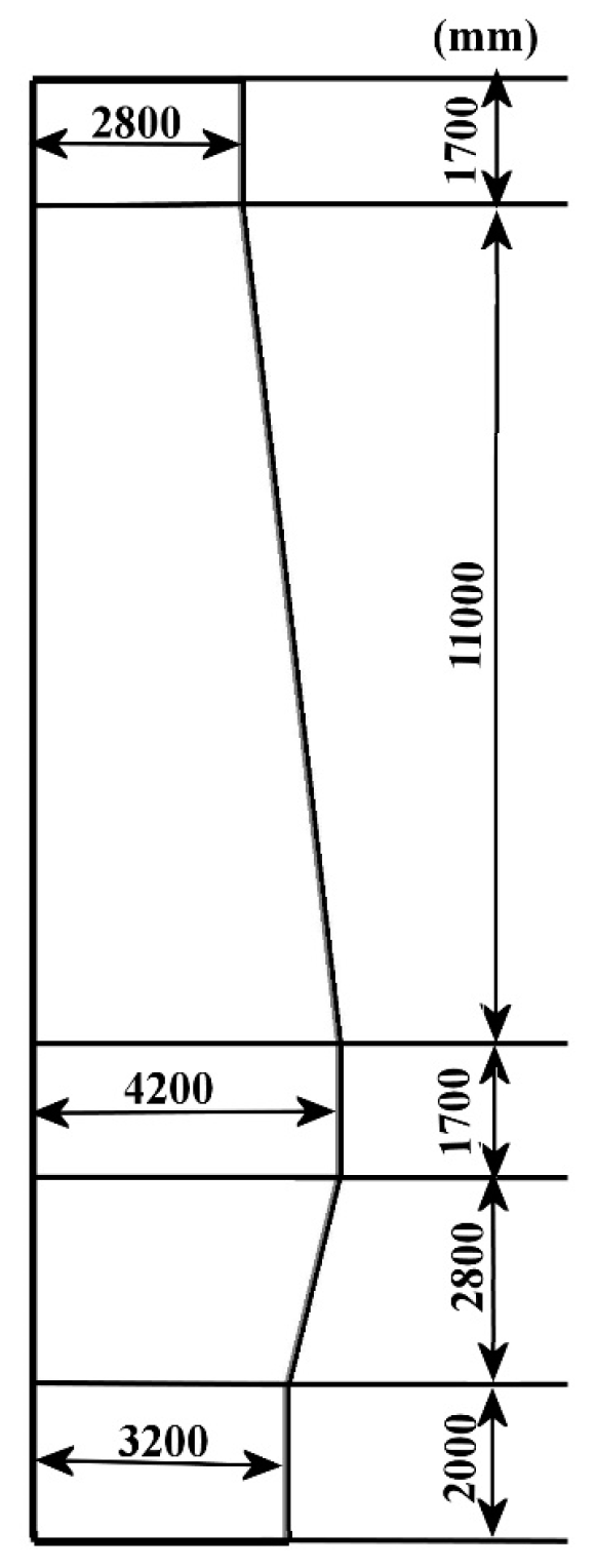
The BF for investigation is with an inner volume of 820 m3, producing 2950 tons of hot metal per day (tHM/d). Eighteen tuyeres are installed on its lower sidewall. Its schematic diagram and size are shown in Figure 1. The normal operation conditions of BF are listed in Table 1. The properties of scrap are shown in Table 2. The slight oxidation on the scrap surface is ignored.
In the BF operation with scrap charging, the scrap charging region covers from the mid radius to the wall, and the amount of scrap in the ore batch is fixed at 3.2 t, which is approximately 12% of the original ore-batch weight. Seven cases were investigated and their conditions are listed in Table 3. The thermal conditions of the raceway (PC injection rate and blast flow rate) are constant in all cases.
3. Model Development
The BF ironmaking is a very complex process, so nowadays novel processes involved in BF are usually investigated by numerical simulations. Numerical simulations can offer the scholars very detailed information to examine their feasibility, understand their mechanisms, and optimize their parameters [16,17,18]. A computational fluid dynamic (CFD) model based on a full-scale BF was developed by the current authors previously [19]. The model is two-dimensional, axisymmetric, and steady. In the model, the gas-phase and solid-phase behaviors in BF are represented by the conservation of mass, momentum, energy, and species. The behaviors of other phases (molten iron, molten slag, and pulverized coal fines) are treated using simplified methods. The model is modified to accommodate the BF operation with scrap charging. Definitions or values of most variables in the model are detailed in [19].
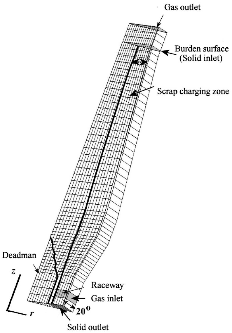
The grid used for the simulation is a two-dimensional structure grid, including 780 cells (Figure 2). The calculation of the cell volumes is based on 20 degrees in the circumferential direction. The deadman zone and the raceway zone are predetermined in the grid according to the research of Austin [20] and Gupta [21]. The porosity of the cohesive zone (CZ), dripping zone (DZ), and deadman are 0.15, 0.30, and 0.15, respectively.
The reactions involved in the model are listed in Table 4. The iron in scrap and the iron in sinter are treated separately, since they undergo different reaction schemes. After the scrap is charged into the blast furnace, it is heated up through heat exchange with the ascending gas. When the scrap continues to descend and enters the high-temperature zone, softening and melting of the scrap take place. Therefore, only Reaction (9) in Table 4 is involved in the scrap. Rate of Reaction (9) is similar to that of the sinter. The scrap melting onset temperature is taken to be the iron eutectic point of 1423 K, therefore, the temperature range of Reaction (9) is from 1423 to 1673 K [11].
The gas flow is considered as the gas flow through the porous bed. The porosity and particle size of the solid burden vary in BF and are calculated according to the method given by Austin [20]. The gas phase is considered to be an ideal gas. The general governing equation for the gas phase is Equation (1), in which, the superficial gas velocity is adopted. The terms to represent φ, Γφ, and Sφ in Equation (1) are listed in Table 5.
A non-slip wall condition for the gas velocity and an impermeable condition for the gas species are defined on the BF wall. The heat loss rate of the gas energy on the BF wall is calculated by . The PC particles are gasified in the raceway zone reaching a burnout rate of more than 90% within 20 ms [22]. Therefore, the combustion products of the blast and the PC through Reaction (4) form the inlet condition for the gas phase in the model. At the gas outlet, a fully-developed gas flow is assumed.
The solid flow in BF could be treated as a viscous flow. The viscous model [23] and the treatment method of the deadman zone given by Austin [24] are applied. The solid phase consists of coke, sinter, and scrap. Each component has its physical properties. Above the CZ, the overall physical properties of the solid phase are calculated by averaging the physical properties of the components based on their volume fractions. The general governing equation of the solid phase is Equation (2), in which, the solid bulk density and the solid physical velocity are adopted. The terms to represent ϕ, Γϕ, and Sϕ in Equation (2) are listed in Table 6. For ensuring a stable solid flow, the reaction rate of the coke is not included in Table 6.
A fluid-slip boundary is applied for the solid velocity on the BF wall. Heat loss of the solid phase on the BF wall is not considered. The inlet conditions of the solid phase are established according to the BF operation conditions. At the solid outlet, the solid phase reaches a fully-developed flow.
The above two sets of equations (Equations (1) and (2)) are solved numerically using the commercial software package PHOENICS [25] and an in-house developed code. All the equations are solved simultaneously. In addition to the examination of the convergence of gas and solid flow fields, the mass balance of the removable element O and the element Fe are examined. The convergence criteria are Equations (3) and (4):
where is the mass supply rate of element O in the solid phase at the solid inlet, and is the mass supply rate of element Fe in the solid phase at the solid inlet.
The gas and solid inlet conditions of all investigated cases are shown in Table 7, which is calculated based on Table 2 and Table 3. The results of case A are kept as reference values for other cases. For each case, the coke supply rate is determined using a trial and error method. The convergence criteria for the mass balance of element C in the coke is Equation (5):
where and are the mass supply rates of element C in the coke, and element Fe in the solid burden at the solid inlet, respectively; [%C] is the carbon content in molten iron; and is the rate of carbon consumed by other reactions, such as silica and manganese oxide reductions, which is determined by the base case (case A).
4. Results and Discussion
4.1. Effect of Charging Scrap on the BF Internal State
Cases A, B, and F were investigated and compared at first. Case A (the base case) represents the BF normal operation, Case B is the BF operation with extra scrap addition, and case F is the BF operation with an equal-mass replacement of sinter with scrap.
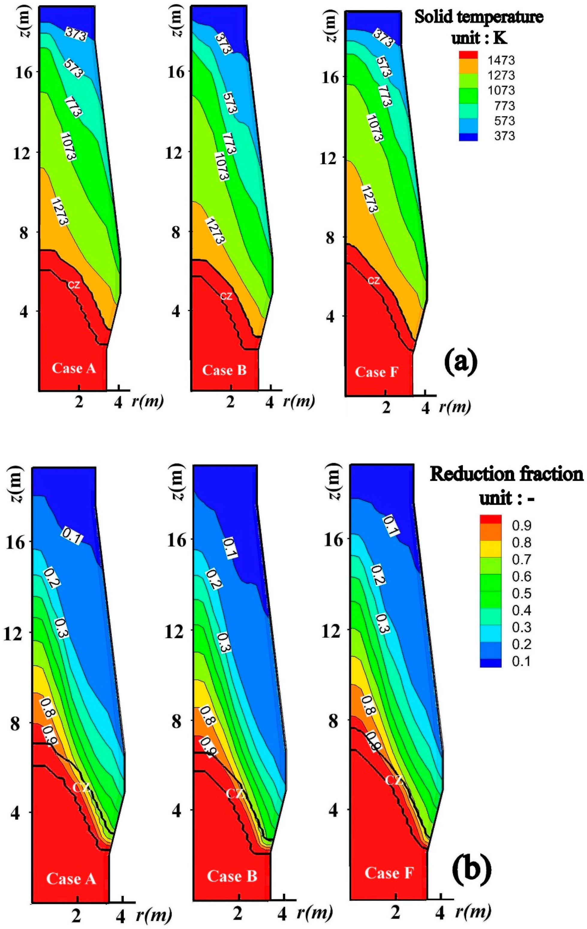
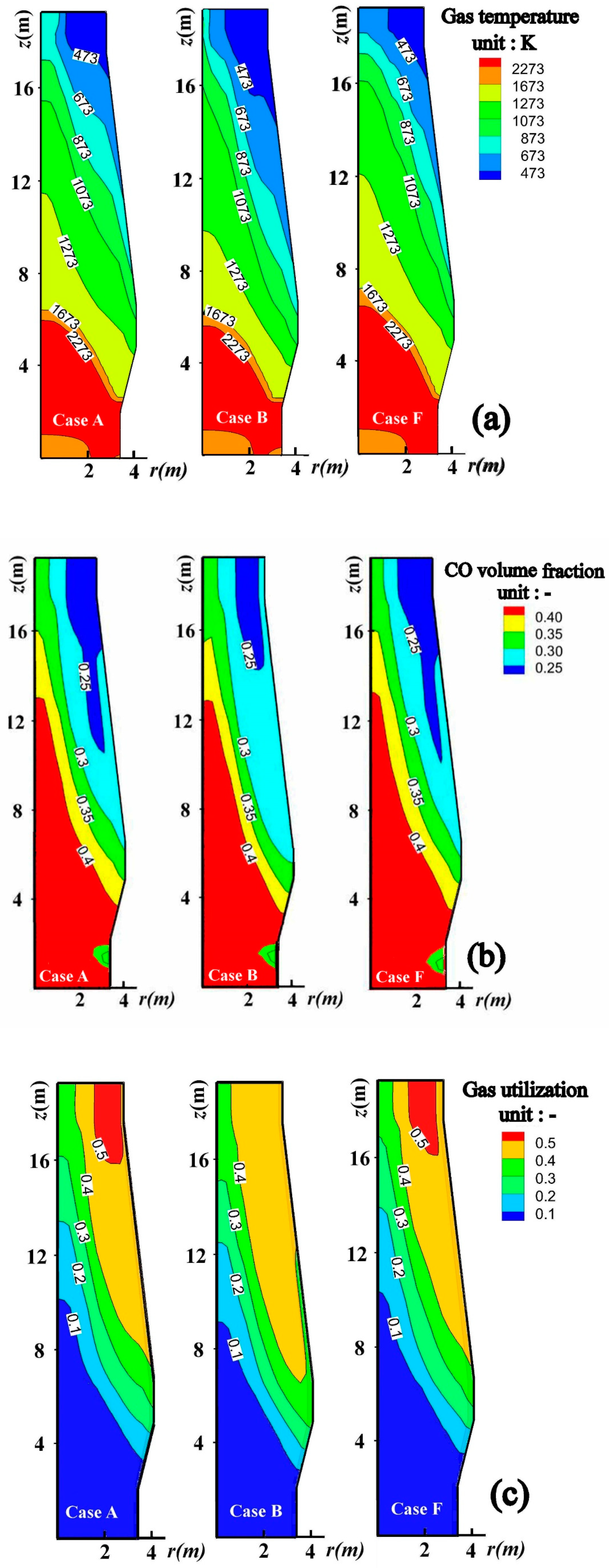
The simulation results of the in-furnace state in cases A, B, and F are shown in Figure 3 and Figure 4. Figure 3 shows the results of the solid behavior and Figure 4 shows the results of the gas behavior. The simulation results of case B in Figure 3 and Figure 4 reveal the influence of the extra scrap addition on the BF in-furnace state. Compared to case A, the increase of the solid-phase temperature is delayed (e.g., comparing cases A and B in Figure 3a, the lines 673 and 1073 K in case B move downward), the CZ position becomes lower, and the gas-phase temperature also shows a faster decrease in the upper BF in case B (e.g., comparing cases A and B in Figure 4a, lines 673 and 1073 K in case B move downward). The extra scrap addition in BF leads to an increase of the heat demand of solid burden (both sensible and latent heat) and an increase of the charging rate of solid burden, but the input heat is maintained as the blast flow rate and the PC injection rate is constant. As a result, the scrap exhibits a cooling effect on the shaft. Since the sinter reduction has a strong temperature dependence [26], its reduction is retarded by charging scrap (e.g., comparing cases A and B in Figure 3b, the distance between lines 0.1 and 0.4 in case B becomes larger). A decrease of sinter gaseous reduction in the upper BF will cause an increase of direct reduction, so the CO generating rate in the lower BF is increased by adding scrap. Therefore, the CO fraction in the upper BF tends to be increased (e.g., in Figure 4b, the lines 0.25 and 0.3 in case B move upward in comparison to case A); and accordingly, the local gas utilization decreases (e.g., in Figure 4c, the line 0.5 exists in case A, however, it disappears in case B). Though extra scrap addition can improve the BF productivity and thermal efficiency, its deficiencies are evident. It causes a decrease in local gas utilization, a decrease of sinter reduction in upper BF, and the lowering of CZ position. CZ with a too low position is not favored, since it suppresses the activity of lower BF and destroys the bosh gas distribution, leading to the unstable BF running [27,28].
The simulation results in case F in Figure 3 and Figure 4 reveal the influence of partial replacement of the sinter with scrap on BF the in-furnace state. By the substitution of sinter with scrap, the heat consumption for sinter reduction and heating is reduced, compensating the heat requirement of the scrap. As a result, the solid-phase temperature increase becomes faster in the upper BF (in Figure 3a, lines 673 and 1073 K in case F move upward in comparison to case B), the CZ moves upward, and the gas-phase temperature presents a slower decrease during its ascending (e.g., in Figure 4a, lines 473 and 1073 K in case F move upward in comparison to case B). The higher shaft temperature is beneficial for the sinter reduction (e.g., in Figure 3b, the distance between lines 0.1 and 0.4 becomes smaller in case F in comparison to case B), therefore, by the equal-mass replacement of sinter with scrap, the local CO fraction tends to be decreased (e.g., in Figure 4b, the lines 0.25 and 0.30 in case F move downward in comparison to case B), and correspondingly, the local gas utilization becomes higher (e.g., in Figure 4c, the line 0.5 exists in case F but it disappears in case B). The above analysis indicates that the partial replacement of sinter with scrap in BF can mitigate the negative effects induced by scrap charging and make the BF performance better.
4.2. Optimization of BF Operation with Scrap Charging
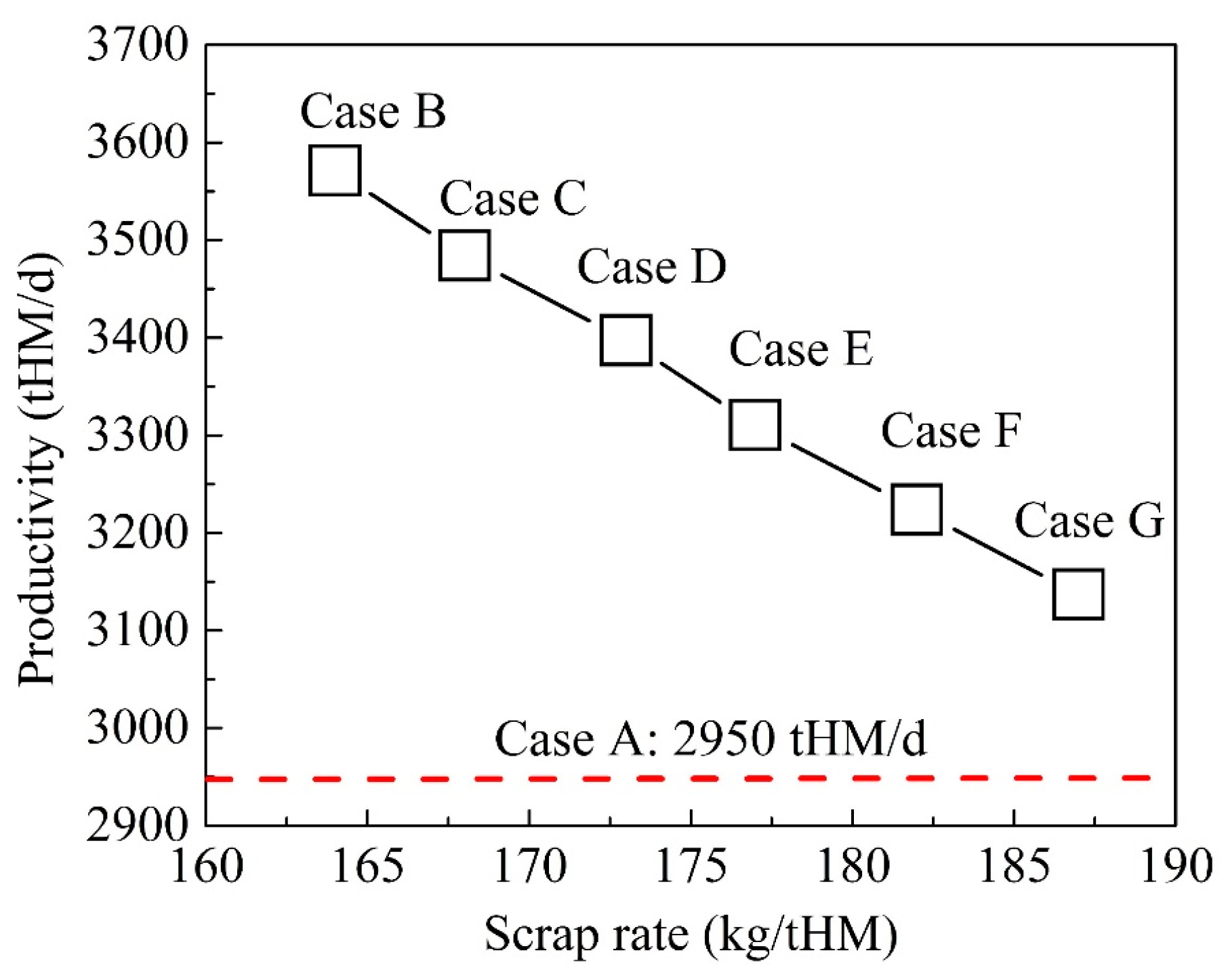
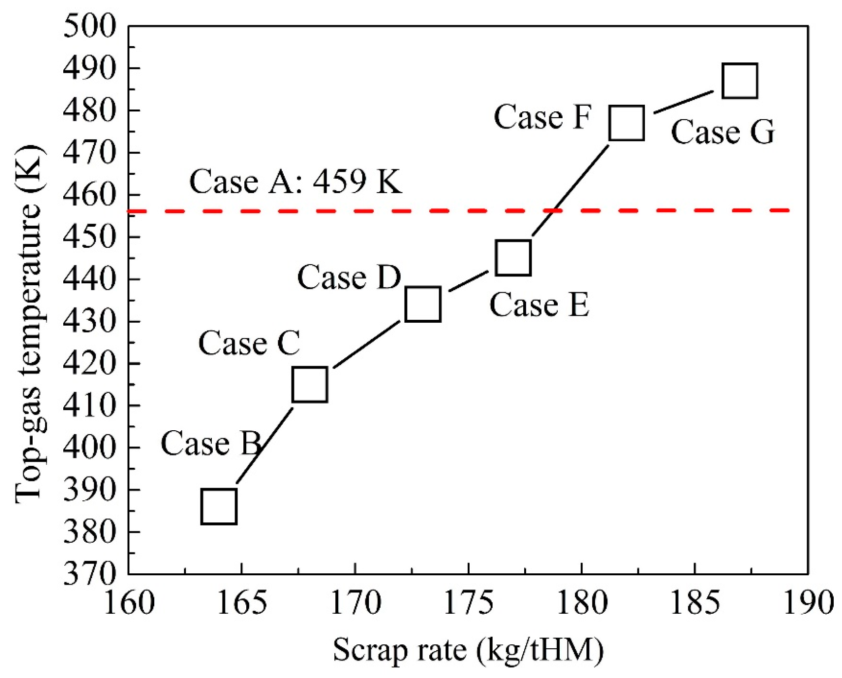
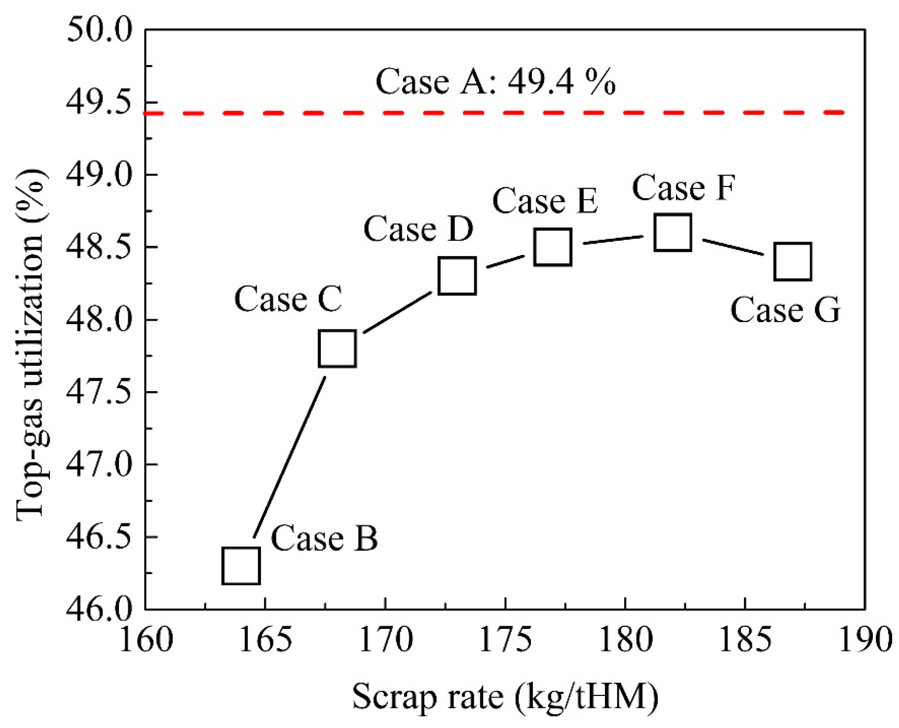
The scrap rate (scrap weight in producing one-ton hot metal) and ore rate in all individual cases in Table 3 were calculated based on the Fe balance and the results are shown in Table 8. From Table 8, it could be seen that less sinter is needed in producing one-ton hot metal by introducing scrap. The main operation indices of all cases were calculated and their respective relations with the scrap rate are plotted in Figure 5, Figure 6 and Figure 7 to determine optimal conditions for the BF operation with scrap charging.
Figure 5 is the change in BF productivity with the scrap rate. Due to the iron content of approximately 100% in scrap, all individual cases with scrap charging have a higher BF productivity than the base case. Figure 5 also shows that BF productivity decreases linearly with the increase in the scrap rate. Figure 6 is the change in the BF top-gas temperature with the scrap rate. It is seen that the top-gas temperature increases with the increase of scrap rate. At the scrap rate of 178 kg/tHM, the top-gas temperature is close to that of the base case. Therefore, when the scrap rate is beyond 178 kg/tHM, the BF thermal efficiency will be lower than that of the base case; otherwise, it is higher. Figure 7 is the change in the BF top-gas utilization with the scrap rate. The top-gas utilization reaches its maximum value of 48.5% at a scrap rate of 183 kg/tHM. When the scrap rate is below 183 kg/tHM, the sinter reduction is accelerated as the shaft temperature is improved by the replacement of sinter with scrap, so the top-gas utilization improves. However, when the scrap rate surpasses 183 kg/tHM, the sinter fraction in the ore batch is considerably reduced and thus, the conversion of CO to CO2 in the gas-phase becomes slower, resulting in a decrease in top-gas utilization.
In the BF operation, in addition to smooth running, the top-gas temperature is required to be beyond 423 K for the subsequent dust-removing process from BF gas [29,30], and it is desired that the top-gas utilization is as high as possible. Considering BF thermal efficiency and top-gas utilization, the operation conditions in case E are optimal. In case E, the BF productivity is 3310 tHM/d, the BF top gas utilization is 48.5%, and the BF top gas temperature is 445 K.
4.3. Estimation on Energy Saving
Reducing agent consumptions in cases E and A were compared and the results are listed in Table 9. In Table 9, the coke consumption rate is calculated using in item I, using in item II, and using in item III. Moreover, it is calculated assuming that the carbon content in molten iron is 5 wt% in item IV and is determined by the carbon balance using the reference case (case A) in item V. Furthermore, the coke consumption rate in item V is not changed by mixing approximately 10% scrap in the ore burden in the BF operation.
Table 9 shows that the PC rate (evaluated in kg/tHM) in case E is decreased by 16.3 kg/tHM in comparison to case A. The decrease is attributed to an increase in BF productivity. Table 9 also shows that the coke rate (evaluated in kg/tHM) in case E decreases by 39.8 kg/tHM in comparison to case A. In the decrease of the coke rate, 7.7 kg/tHM is from the reduced consumption in the solution-loss reaction, 11.1 kg/tHM from the reduced consumption in the molten slag direct reduction, and the remaining is from the increase in BF productivity.
5. Conclusions
A numerical investigation was carried out on the BF operation with scrap charging using a BF with an inner volume of 820 and a productivity of 2950 tHM/d. The following conclusions can be drawn.
(1) Extra scrap addition in the ore batch is not favored. Although the BF productivity and thermal efficiency are improved, it has negative effects, including the decrease of shaft temperature, the decrease of local gas utilization, and the lowering CZ position, leading to an unstable BF running.
(2) Partial replacement of sinter with scrap in the ore batch can mitigate the negative effects induced by extra scrap charging. It can be applied to make the BF performance better.
(3) Scrap rate of 178 kg/tHM is optimal, under which, the BF reaches a productivity of 3310 tHM/d, a top-gas utilization of 48.5%, and a top-gas temperature of 445 K. Compared with the base case, in the BF operation with scrap charging, the BF productivity is increased by 360 kg/tHM, while its PC rate and coke rate are decreased by 16.3 kg/tHM and 39.8 kg/tHM, respectively.
Author Contributions
Conceptualization, H.T. and X.S.; methodology, H.T.; software, H.T.; validation, Z.L. and Z.Y.; formal analysis, Z.L.; investigation, Z.Y.; resources, X.S.; data curation, Z.L.; writing—original draft preparation, Z.L., and Z.Y.; writing—review and editing, H.T.; visualization, Z.L.; supervision, Q.X. All authors have read and agreed to the published version of the manuscript.
Funding
The National Natural Science Foundation of China (grant number: U1960205).
Acknowledgments
The authors thank the National Natural Science Foundation of China for supporting this work.
Conflicts of Interest
The authors declare no conflict of interest.
Nomenclature
| Aface | cell face area, m2 |
| A | specific area, m2/m3 |
| ak | rate coefficient of interface k of the three-interface shrinking core model, m/s |
| Cp | heat capacity, J/(kg⋅K) |
| d | diameter, m |
| E | enthalpy source, J/(m3·s) |
| H | total enthalpy, J/kg |
| ΔHi | reaction heat of reaction i, J/kmol |
| k | reaction rate constant/mass transfer coefficient, 1/s, m/s |
| M | molar weight (kg/kmol) |
| m | mass supply/consumption rate of the given element, kg/s |
| P | pressure, Pa |
| Pr | Prandtal number, - |
| Ri | reaction rate of reaction i, kmol/(m3⋅s) |
| Re | Reynolds number, - |
| S | source term, units vary |
| Sc | Schmidt number, - |
| T | temperature, K |
| VCell | volume of cell, m3 |
| y | mass fraction, - |
| Vector | |
| gas flow resistance, N/m3 | |
| normal unit vector on the cell face | |
| gas superficial velocity vector, m/s | |
| solid physical velocity vector, m/s | |
| Greek symbol | |
| ϕ, φ | general dependent variable |
| Γ | general diffusion coefficient |
| α | volume fraction, - |
| ⍴ | density, bulk density of solid phase and its species or element, kg/m3 |
| η | fraction of the liquid phase, - |
| λ | thermal conductivity, W/(m⋅K) |
| ε | porosity, - |
| μ | fluid viscosity, kg/(m⋅s) |
| Subscript | |
| s | solid variable |
| g | gas variable |
| l | liquid variable |
| coke | coke variable |
| ore | ore variable |
| scrap | scrap variable |
| species or element name variable of assigned species or element | |
References
- World Steel Association. Steel’s Contribution to a Low Carbon Future and Climate Resilient Societies—World Steel Position Paper; World Steel Association: Brussels, Belgium, 2020; ISBN 978-2-930069-83-8. Available online: https://www.worldsteel.org/en/dam/jcr:7ec64bc1-c51c-439b-84b8-94496686b8c6/Position_paper_climate_2020_vfinal.pdf (accessed on 5 October 2020).
- Holappa, L. A general vision for reduction of energy consumption and CO2 emissions from the steel industry. Metals 2020, 10, 1117. [Google Scholar] [CrossRef]
- Wang, C.; Ryman, C.; Dahl, J. Potential CO2 emission reduction for BF–BOF steelmaking based on optimised use of ferrous burden materials. Int. J. Greenh. Gas Control 2009, 3, 29–38. [Google Scholar] [CrossRef]
- Jaimes, W.; Maroufi, S. Sustainability in steelmaking. Curr. Opin. Green Sustain. Chem. 2020, 24, 42–47. [Google Scholar] [CrossRef]
- Yamamoto, T.; Ujisawa, Y.; Ishida, H.; Takatani, K. Operation and design of scrap melting process of the packed bed type. ISIJ Int. 1999, 39, 705–714. [Google Scholar] [CrossRef]
- Janke, D.; Savov, L.; Weddige, H.J.; Schulz, E. Scrap-based steel production and recycling of steel. Mater. Tehnol. 2000, 34, 387. [Google Scholar]
- Oda, J.; Akimoto, K.; Tomoda, T. Long-term global availability of steel scrap. Resour. Conserv. Recyl. 2013, 81, 81–91. [Google Scholar] [CrossRef]
- Vercammen, S.; Chalabyan, A.; Ramsbottom, O.; Ma, J.; Tsai, C.; The Growing Importance of Steep Scrap in China. McKinsey Company 2017. Available online: https://www.mckinsey.com/~/media/mckinsey/industries/metals%20and%20mining/our%20insights/the%20growing%20importance%20of%20steel%20scrap%20in%20china/the-growing-importance-of-steel-scrap-in-china.pdf (accessed on 5 October 2020).
- Huang, J.; Lin, C. Analysis of Cost Benefit Change Brought by Scrap Ratio Increase in Crude Steel Industry; Chinese Logistics and Purchasing: Beijing, China, 2019; pp. 49–50. (In Chinese) [Google Scholar]
- Liu, K.; Xu, D.; Mei, Z.; Wan, J.; Zhu, Z. Technological measures for increasing scrap ratio. China Steel Focus 2020, 9, 1–2. (In Chinese) [Google Scholar]
- Austin, P.R.; Nogami, H.; Yagi, J. Computational investigation of scrap charging to the blast furnace. ISIJ Int. 1998, 38, 697–703. [Google Scholar] [CrossRef]
- Ryman, C.; Larsson, M. Reduction of CO2 emissions from integrated steelmaking by optimised scrap strategies: Application of process integration models on the BF–BOF system. ISIJ Int. 2006, 46, 1752–1758. [Google Scholar] [CrossRef] [Green Version]
- Deng, Y.; Zhang, J.; Liu, R.; Jiao, K.; Yan, B. Smelting practice of scrap addition in blast furnace and theoretical analysis of cost saving. J. Iron Steel Res. Int. 2020, 27, 1005–1010. [Google Scholar] [CrossRef]
- Li, H.; Mo, C.; Tang, Z.; Wang, Z.; Pan, J. Analysis and practice of cost reduction based on addition of scrap steel in Liusteel 5# blast furnace. Ind. Furn. 2018, 40, 39–42. (In Chinese) [Google Scholar]
- Liu, L.; Chen, S.; Chen, Y. Experiment of increasing output based on addition of scrap steel in Shaosteel 6# blast furnace. Ironmaking 2019, 38, 37–39. (In Chinese) [Google Scholar]
- Chu, M.; Yang, X.; Shen, F.; Yagi, J.; Nogami, H. Numerical simulation of innovative operation of blast furnace based on multi-fluid model. J. Iron Steel Res. Int. 2006, 13, 8–15. [Google Scholar] [CrossRef]
- Okosun, T.; Silaen, A.K.; Zhou, C.Q. Review on computational modeling and visualization of the ironmaking blast furnace at Purdue University Northwest. Steel Res. Int. 2019, 90, 1900046. [Google Scholar] [CrossRef]
- Shen, Y.; Guo, B.; Chew, S.; Austin, P.; Yu, A. Three-dimensional modeling of flow and thermochemical behavior in a blast furnace. Metall. Mater. Trans. B 2015, 46, 432–448. [Google Scholar] [CrossRef]
- Tang, H.; Rong, T.; Fan, K. Numerical investigation of applying high-carbon metallic briquette in blast furnace ironmaking. ISIJ Int. 2019, 59, 810–819. [Google Scholar] [CrossRef] [Green Version]
- Austin, P.R.; Nogami, H.; Yagi, I.J. A mathematical model of four phase motion and heat transfer in the blast furnace. ISIJ Int. 2019, 37, 458–467. [Google Scholar] [CrossRef]
- Gupta, G.S.; Rudolph, V. Comparison of blast furnace raceway size with theory. ISIJ Int. 2006, 46, 195–201. [Google Scholar] [CrossRef] [Green Version]
- Mathieson, J.G.; Truelove, J.S.; Rogers, H. Toward an understanding of coal combustion in blast furnace tuyere injection. Fuel 2005, 84, 1229–1237. [Google Scholar] [CrossRef]
- Chen, J.; Akiyama, T.; Nogami, H.; Yagi, I.J.; Takahashi, H. Modeling of solid flow in moving beds. ISIJ Int. 1993, 33, 664–671. [Google Scholar] [CrossRef]
- Austin, P.R.; Nogami, H.; Yagi, J.I. A mathematical model for blast furnace reaction analysis based on the four fluid model. ISIJ Int. 1997, 37, 748–755. [Google Scholar] [CrossRef]
- CHAM. PHOENICS User Document; CHAM Ltd.: London, UK, 2000. [Google Scholar]
- Tokuda, M.; Yoshikoshi, H.Y.; Ohtani, M. Kinetics of the reduction of iron ore. Trans. ISIJ. 1973, 13, 351–363. [Google Scholar] [CrossRef]
- Ueda, S.; Kon, T.; Kurosawa, H.; Natsui, S.; Ariyama, T.; Nogami, H.J.I.I. Influence of shape of cohesive zone on gas flow and permeability in the blast furnace analyzed by DEM-CFD model. ISIJ Int. 2015, 55, 1232–1236. [Google Scholar] [CrossRef] [Green Version]
- Nath, N.K. Simulation of gas flow in blast furnace for different burden distribution and cohesive zone shape. Mater. Manuf. Process. 2002, 17, 671–681. [Google Scholar] [CrossRef]
- Wang, J.; Guo, Z.; Wang, Z. Application and practice of fully dry cloth-bag dust removing technology of No. 4 BF in baogang. Energy Metall. Ind. 2007, 1, 5–11. (In Chinese) [Google Scholar]
- Li, H.; Tao, W.; Feng, X.; Sun, Z. Application of the dry cloth-bag dedusting technology in baosteel no. 1 blast furnace. Baosteel Technol. 2010, 5, 15–19. (In Chinese) [Google Scholar]
Figure 1.
Schematic diagram of the Blast Furnace (BF) and its size (mm).

Figure 2.
Mesh placement of the model.

Figure 3.
Simulation results of solid phase in the BF of cases A, B, and F: (a) Profile of solid-phase temperature; and (b) profile of sinter reduction fraction.
Figure 3.
Simulation results of solid phase in the BF of cases A, B, and F: (a) Profile of solid-phase temperature; and (b) profile of sinter reduction fraction.

Figure 4.
Simulation results of gas phase in the BF of cases A, B, and F: (a) Profile of gas-phase temperature; (b) profile of CO volume fraction; and (c) profile of local gas utilization.
Figure 4.
Simulation results of gas phase in the BF of cases A, B, and F: (a) Profile of gas-phase temperature; (b) profile of CO volume fraction; and (c) profile of local gas utilization.

Figure 5.
Change in BF productivity with scrap rate.

Figure 6.
Change in BF top-gas temperature with scrap rate.

Figure 7.
Change in BF top-gas utilization with scrap rate.


Table 1.
Normal operation conditions of BF.
| Parameter | Value |
|---|---|
| Output (t/d) | 2950 |
| Blast temperature (K) | 1423 |
| Blast flow rate (Nm3/min) | 2100 |
| Blast oxygen enrichment (%) | 4.5 |
| BF top pressure (Pa) | 2.0 × 10⁵ |
| PC injection rate (kg/s) | 5.12 |
| Weight of ore batch (t) | 27.0 |
| Weight of coke batch (t) | 2.9 |
| Solid temperature (K) | 300 |
| Properties of ore burden (78% sinter, 14% pellet, and 8% lump ore) | Composition: TFe: 56.3 wt%, FeO: 7.19 wt%, CaO: 8.60 wt%, SiO2: 7.07 wt%, Al2O3: 2.19 wt%; Porosity: 0.35; Bulk density: 1750 kg/m3; Average size: 20 mm; Ore rate: 1698 kg/tHM. |
| Properties of coke | Composition: Fixed carbon: 88.0 wt%, ash: 12.0 wt%; porosity: 0.50; Bulk density: 500 kg/m3; Average size: 40 mm; Coke rate: 385 kg/tHM. |
| Properties of pulverized coal (PC) | Composition C: 80.0 wt%, H: 4.0 wt%, O: 3.5 wt%, N: 2.0 wt%, and S: 0.32 wt%; H2O: 4.0 wt%, ash: 7.0 wt%; Average size: 90 µm; PC rate: 150 kg/tHM. |
| Properties of molten iron and molten slag | Molten iron: [% C]: 5.0 wt%, Temperature: 1773 K, Average heat capacity: 1000 J/kg; Slag rate: 360 kg/tHM |
Table 2.
Properties of scrap.
| Average Size (mm) | Bulk Density (kg/m3) | Porosity (-) | Chemical Composition (wt%) | ||||
|---|---|---|---|---|---|---|---|
| C | Si | Mn | P | S | |||
| 12 | 5320.0 | 0.3 | 0.24 | 0.31 | 1.39 | 0.024 | 0.027 |
Table 3.
Simulation conditions.
| Case | Weight of Ore Batch (t) | Sinter Weight in Ore Batch (t) | Scrap Weight in Ore Batch (t) | Decrease of Sinter in Ore Batch (t) |
|---|---|---|---|---|
| A (base case) | 27.0 | 27.0 | 0 | 0 |
| B | 30.2 | 27.0 | 3.2 | 0 |
| C | 29.4 | 26.2 | 3.2 | 0.8 |
| D | 28.6 | 25.4 | 3.2 | 1.6 |
| E | 27.8 | 24.6 | 3.2 | 2.4 |
| F | 27.0 | 23.8 | 3.2 | 3.2 |
| G | 26.2 | 23.0 | 3.2 | 4.0 |
Table 4.
Chemical reactions involved in the model.
| No. | Reaction | Reaction Rate, kmol/(m3⋅s) | Expression |
|---|---|---|---|
| 1 | 3Fe2O3(s) + CO(g) = 2Fe3O4(s) + CO2(g) | R1 | |
| 2 | Fe3O4(s) + CO(g) = 3FeO(s) + CO2(g) | R2 | |
| 3 | FeO(s) + CO(g) = Fe(s) + CO2(g) | R3 | |
| 4 | C(coke) + 1/2O2(g) = CO(g) | R4 | , , , . For reaction (4), , . For reaction (5), , . |
| 5 | C(coke) + CO2(g) = 2CO(g) | R5 | |
| 6 | Fe(s) = Fe(l) | R6 | . for reactions (6–8); and for reaction (9). |
| 7 | FeO(s) = FeO(l) | R7 | |
| 8 | Gangue(s) = Slag(l) | R8 | |
| 9 | Fe(scrap,s) = Fe(l) | R9 | |
| 10 | FeO(l) + C(s) = Fe(l) + CO(g) | R10 |
Table 5.
Terms in Equation (1) for the gas flow.
| Equation | |||
|---|---|---|---|
| Mass | 1 | 0 | |
| Momentum | |||
| Enthalpy | |||
| Species | 0 | ||
Table 6.
Terms in Equation (2) for the solid flow.
| Equation | |||
|---|---|---|---|
| Continuity | 1 | 0 | |
| Momentum | |||
| Enthalpy | |||
| Species | 0 | 0 | |
| 0 | |||
| 0 | |||
| 0 | |||
| 0 | |||
| 0 | |||
| 0 |
Table 7.
Gas and solid inlet conditions of different cases (1/20 BF volume).
| Condition | Variables | Case A | Case B | Case C | Case D | Case E | Case F | Case G |
|---|---|---|---|---|---|---|---|---|
| Solid inlet conditions | Ore supply rate (kg/s) | 2.90 | 2.90 | 2.81 | 2.73 | 2.64 | 2.56 | 2.47 |
| Scrap supply rate (kg/s) | 0 | 0.34 | 0.34 | 0.34 | 0.34 | 0.34 | 0.34 | |
| Coke supply rate (kg/s) | 0.657 | - | - | - | - | - | - | |
| Solid temperature (K) | 300 | |||||||
| Gas inlet conditions | Gas supply rate (kg/s) | 2.53 | ||||||
| Gas composition (mass fraction) | CO: 0.18, O2: 0.16, and N2: 0.66 | |||||||
| Gas temperature (K) | 2441 | |||||||
Table 8.
Scrap rate in simulated cases.
| Case | A | B | C | D | E | F | G |
|---|---|---|---|---|---|---|---|
| Scrap rate (kg/tHM) | 0 | 165 | 169 | 174 | 178 | 183 | 188 |
| Ore rate (kg/tHM) | 1698 | 1403 | 1396 | 1388 | 1380 | 1371 | 1362 |
Table 9.
Reducing agent rate in cases A and E.
| Reducing Agent | Item | Case A (Base) (kg/tHM) | Case E (kg/tHM)) | |
|---|---|---|---|---|
| PC | I | Combustion at raceway | 150 | 133.70 |
| - | Total | 150 | 133.70 | |
| Coke | I | Combustion at raceway | 196.0 | 175.0 |
| II | Solution loss in upper BF | 36.76 | 29.09 | |
| III | Direct reduction of molten FeO in lower BF | 75.64 | 64.50 | |
| IV | Carburization of molten iron | 57.00 | 57.00 | |
| V | Other (SiO2, and MnO reduction, etc.) | 19.60 | 19.60 | |
| - | Total | 385.00 | 345.20 | |
Publisher’s Note: MDPI stays neutral with regard to jurisdictional claims in published maps and institutional affiliations. |
© 2020 by the authors. Licensee MDPI, Basel, Switzerland. This article is an open access article distributed under the terms and conditions of the Creative Commons Attribution (CC BY) license (http://creativecommons.org/licenses/by/4.0/).
Share and Cite
MDPI and ACS Style
Liu, Z.; Yu, Z.; She, X.; Tang, H.; Xue, Q. Numerical Investigation of Blast Furnace Operation with Scrap Charging. Metals 2020, 10, 1666. https://0-doi-org.brum.beds.ac.uk/10.3390/met10121666
AMA Style
Liu Z, Yu Z, She X, Tang H, Xue Q. Numerical Investigation of Blast Furnace Operation with Scrap Charging. Metals. 2020; 10(12):1666. https://0-doi-org.brum.beds.ac.uk/10.3390/met10121666
Chicago/Turabian StyleLiu, Zhu, Zi Yu, Xuefeng She, Huiqing Tang, and Qingguo Xue. 2020. "Numerical Investigation of Blast Furnace Operation with Scrap Charging" Metals 10, no. 12: 1666. https://0-doi-org.brum.beds.ac.uk/10.3390/met10121666
Note that from the first issue of 2016, this journal uses article numbers instead of page numbers. See further details here.