
The Effect of Different Annealing Strategies on the Microstructure Development and Mechanical Response of Austempered Steels

 , , and
Abstract
:1. Introduction
2. Materials and Methods
3. Results
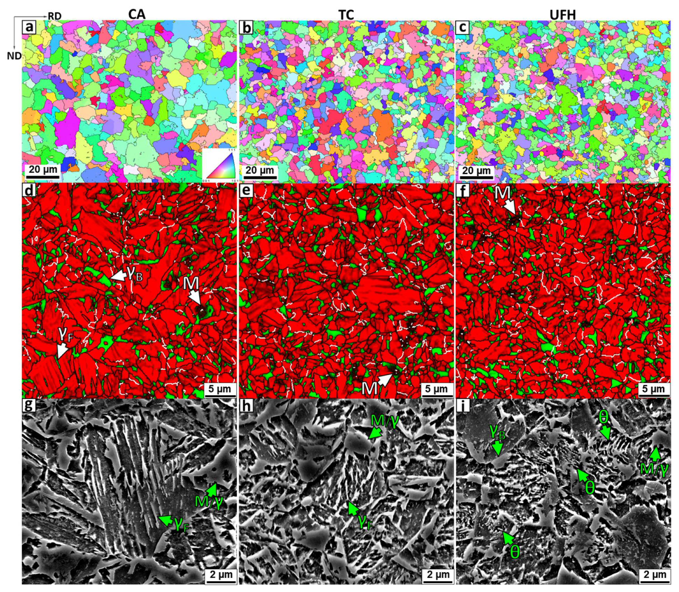
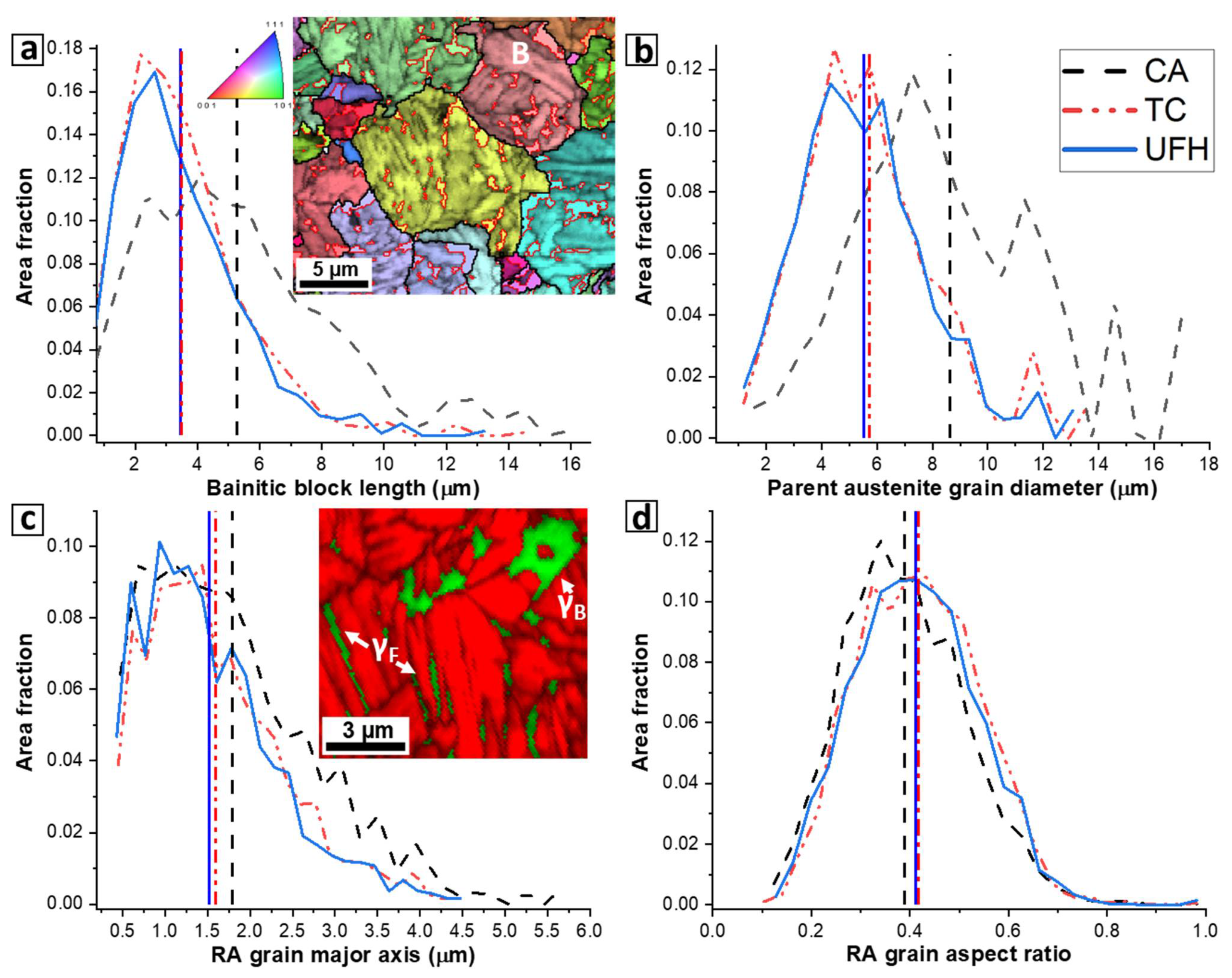
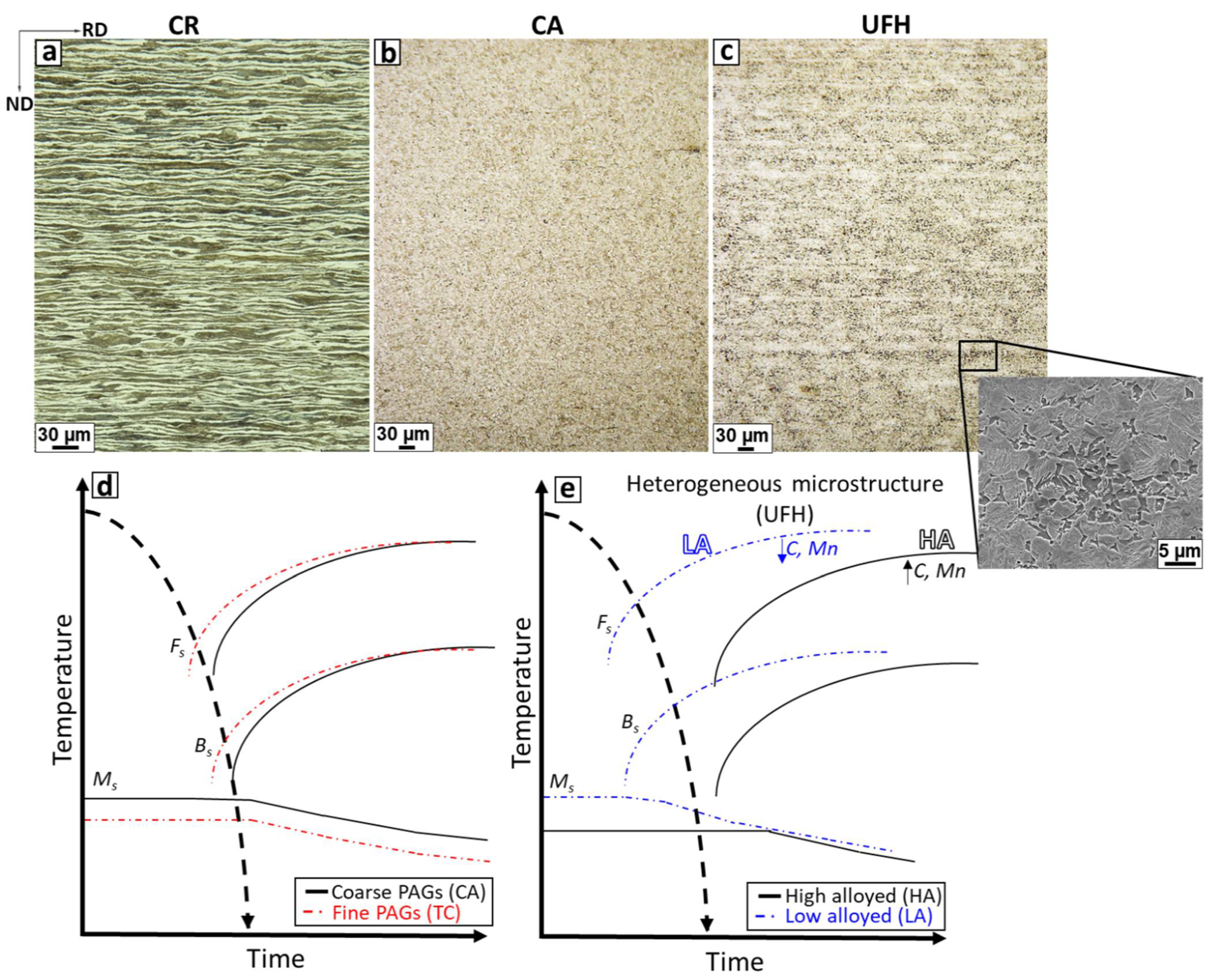
3.1. Microstructure
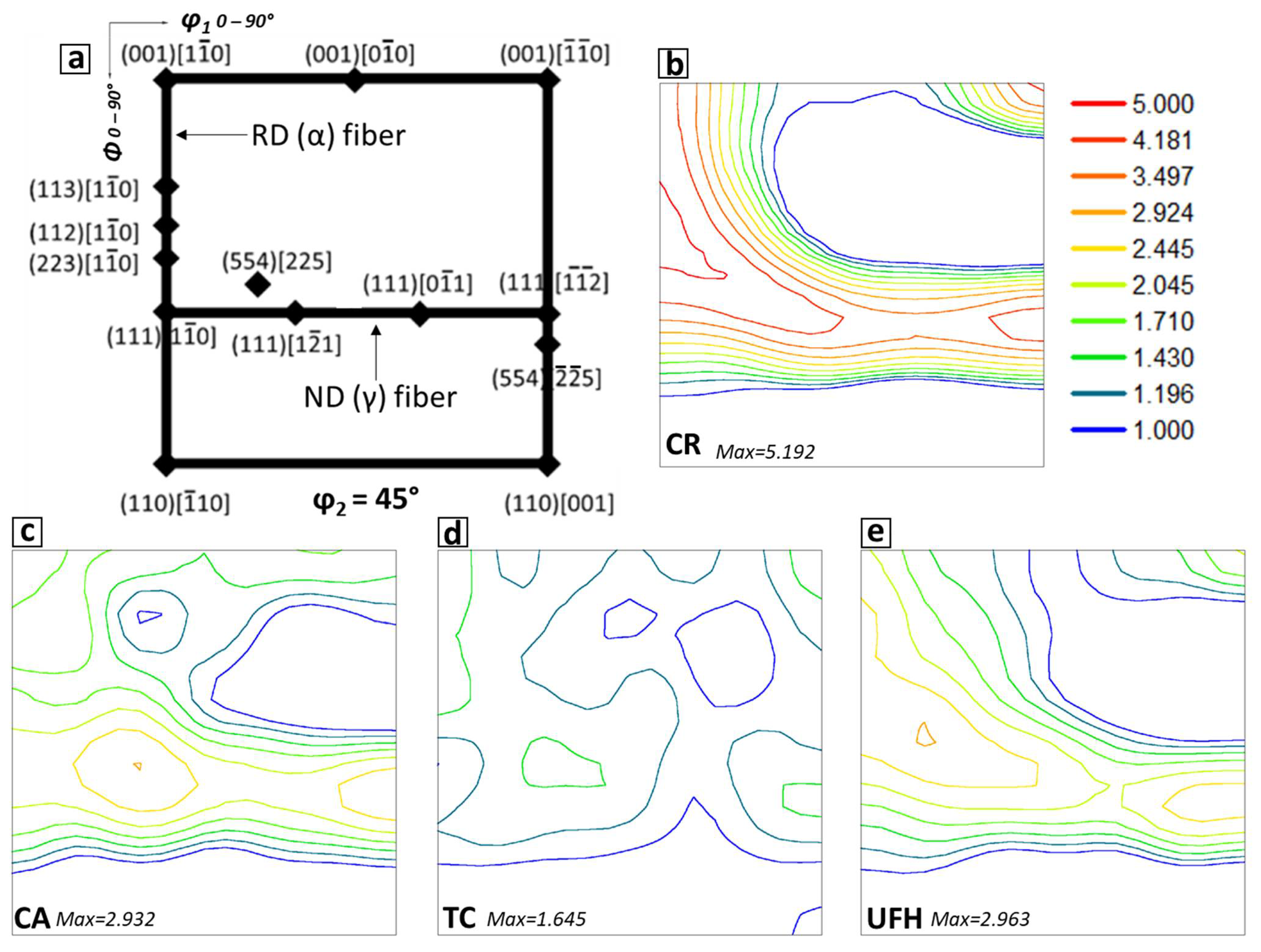
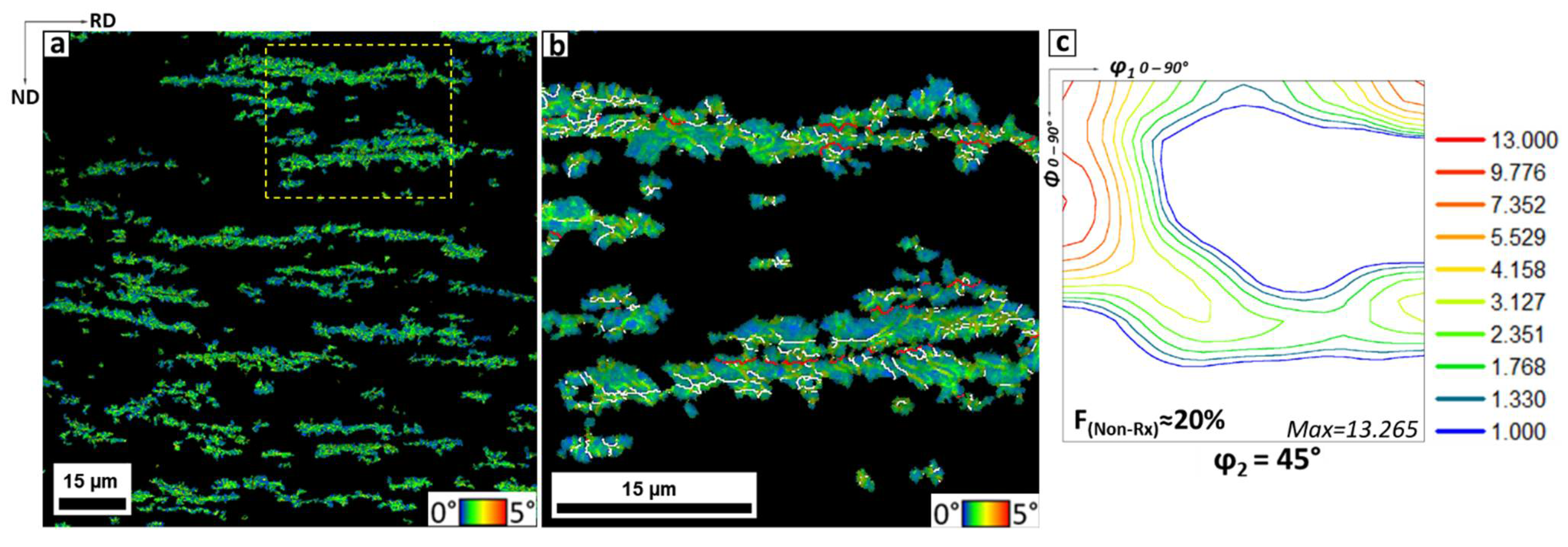
3.2. Textures
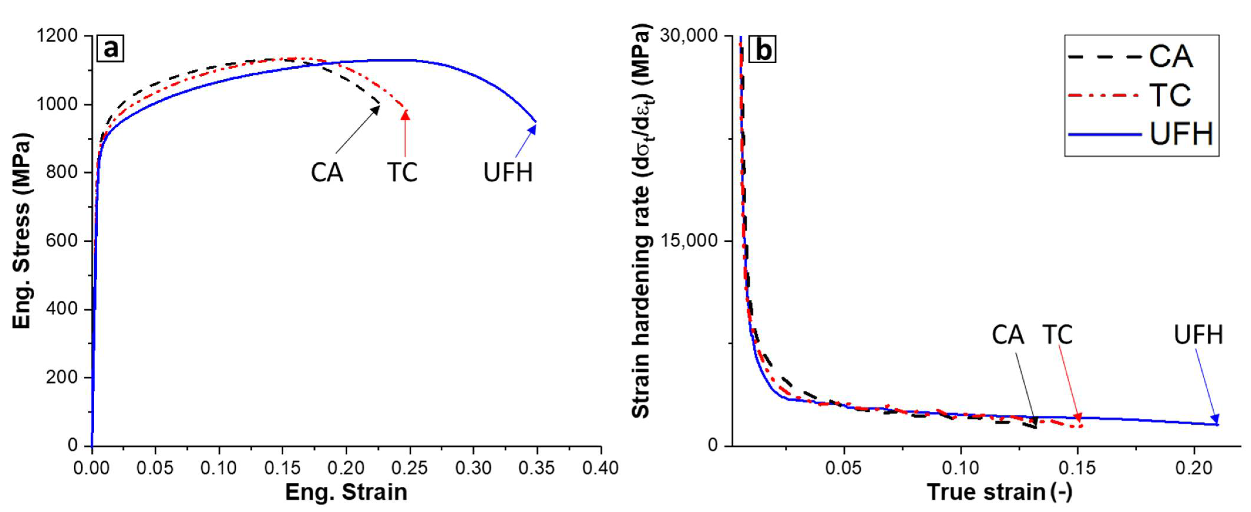
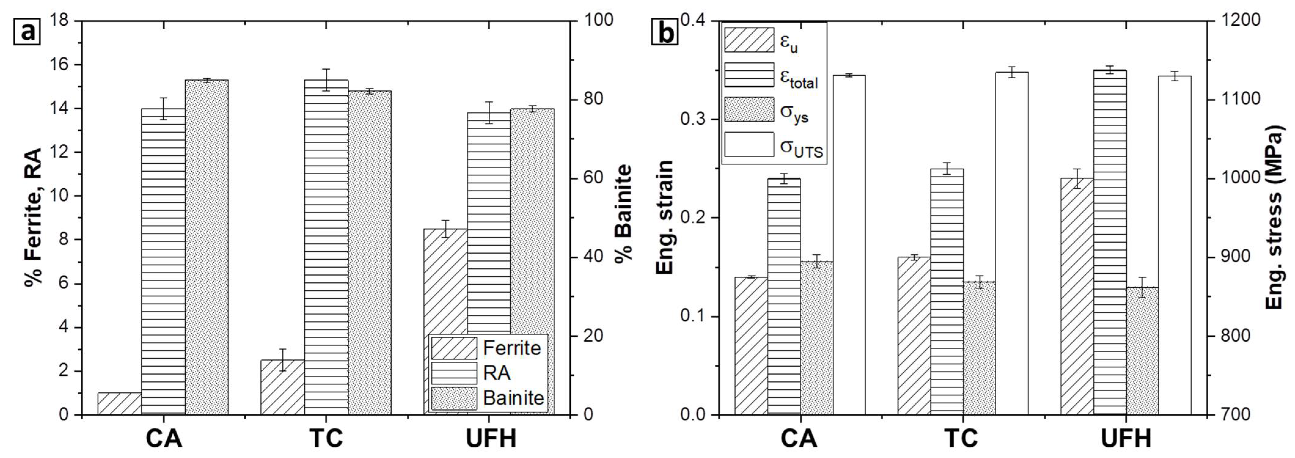
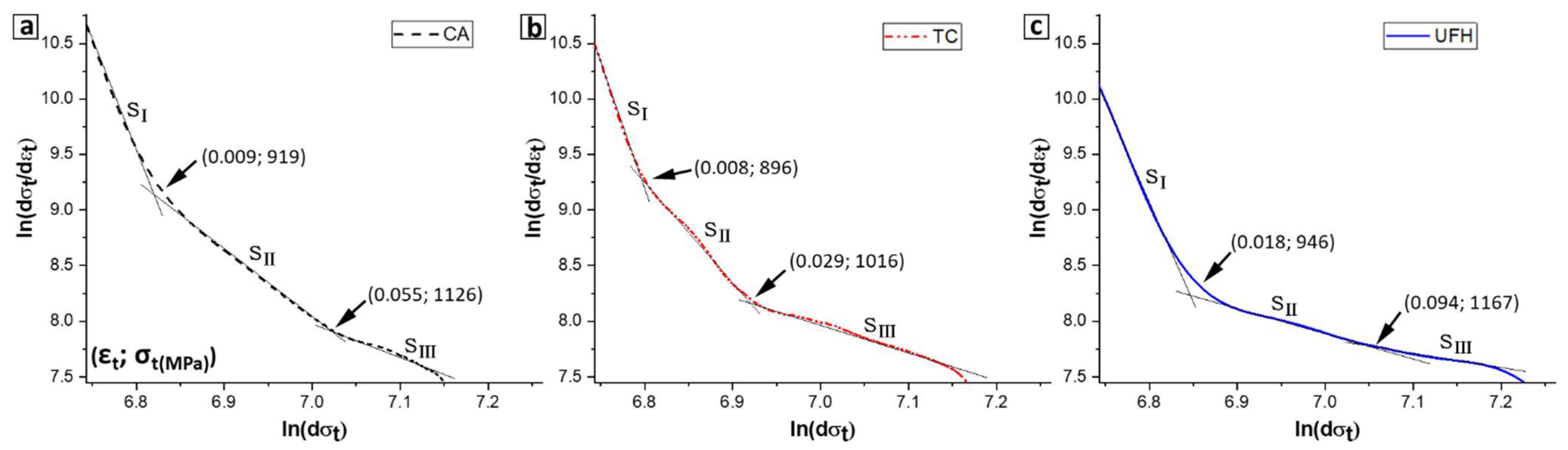
3.3. Mechanical Properties
4. Discussion
5. Conclusions
- Four-step thermo-cycling and ultrafast heating above the AC3 led to finer microstructures than conventional annealing. Retained austenite grain distributions were not greatly influenced by the prior annealing treatment.
- The microstructural refinement attained via thermo-cycling does not show a significant influence on the mechanical response for the studied steels.
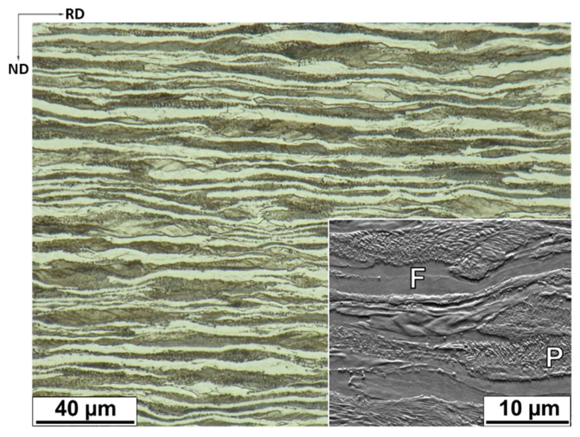
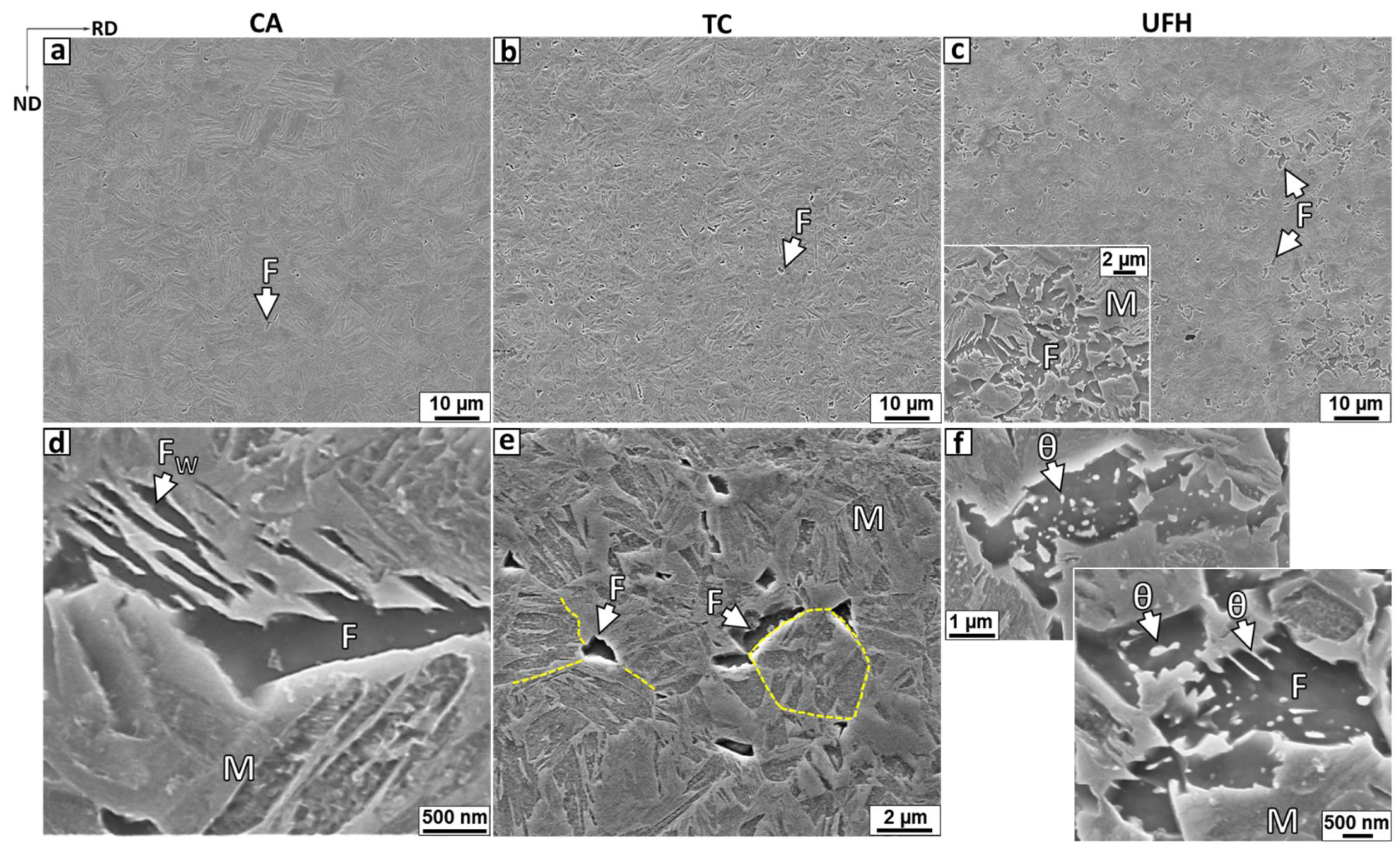
- Ultrafast heating above the AC3 followed by fast cooling to room temperature retains a banded microstructure mainly composed of martensite and ferrite. The banded characteristics of the heat-treated material are similar to the observed in the as-received ferritic–pearlitic steel. Microstructural analysis suggested that the banded microstructure developed after heat treatment arises from local chemical heterogeneities in the parent austenite due to insufficient time for diffusion of alloying elements during the UFH process.
- In contrast to the conventional annealed sample, the grain refined-heterogeneous microstructure produced via a combination of UFH and austempering led to an increase of 40% in total elongation and 50% in energy absorbed measured under uniaxial strain to fracture.
- The enhancement of ductility of the UFH-bainitic steel is reached without sacrificing the strength level. The obtained results suggest that the formation of heterogeneous microstructures via ultrafast heating annealing has a greater influence on the mechanical response than the attained level of grain refinement.
Author Contributions
Funding
Institutional Review Board Statement
Informed Consent Statement
Data Availability Statement
Acknowledgments
Conflicts of Interest
References
- Morrison, W. Effect of grain size on the stress-strain relationship in low-carbon steel. Trans. ASM 1966, 59, 824–846. [Google Scholar]
- Hanamura, T.; Torizuka, S.; Tamura, S.; Enokida, S.; Takech, H. Effect of Austenite Grain Size on the Mechanical Properties in Air-Cooled 0.1c-5Mn Martensitic Steel; Trans Tech Publications Ltd.: Stafa-Zurich, Switzerland, 2014; Volume 783–786, pp. 1027–1032. [Google Scholar] [CrossRef]
- Tomita, Y.; Okabayashi, K. Heat treatment for improvement in lower temperature mechanical properties of 0.40 pct C-Cr-Mo ultrahigh strength steel. Metall. Trans. A 1983, 14, 2387–2393. [Google Scholar] [CrossRef]
- Garcia-Mateo, C.; Caballero, F.G.; Sourmail, T.; Kuntz, M.; Cornide, J.; Smanio, V.; Elvira, R. Tensile behaviour of a nanocrystalline bainitic steel containing 3wt% silicon. Mater. Sci. Eng. A 2012, 549, 185–192. [Google Scholar] [CrossRef] [Green Version]
- Yokota, T.; Mateo, C.G.; Bhadeshia, H.K.D.H. Formation of nanostmctured steels by phase transformation. Scr. Mater. 2004, 51, 767–770. [Google Scholar] [CrossRef] [Green Version]
- Furuhara, T.; Kikumoto, K.; Saito, H.; Sekine, T.; Ogawa, T.; Morito, S.; Maki, T. Phase transformation from fine-grained austenite. ISIJ Int. 2008, 48, 1038–1045. [Google Scholar] [CrossRef] [Green Version]
- Grange, R.A. Strengthening steel by austenite grain refinemet. Trans. ASM 1966, 59, 26–48. [Google Scholar]
- Grange, R.A. The rapid heat treatment of steel. Metall. Trans. 1971, 2, 65–78. [Google Scholar] [CrossRef]
- Baker, T.N. Microalloyed steels Microalloyed steels. Ironmak. Steelmak. 2016, 43, 264–307. [Google Scholar] [CrossRef] [Green Version]
- Buchmayr, B. Thermomechanical Treatment of Steels—A Real Disruptive Technology Since Decades. Steel Res. Int. 2017, 87, 1–14. [Google Scholar] [CrossRef]
- Zhao, J.; Jiang, Z. Thermomechanical processing of advanced high strength steels. Prog. Mater. Sci. 2018, 94, 174–242. [Google Scholar] [CrossRef]
- Dai, Z.; Chen, H.; Ding, R.; Lu, Q.; Zhang, C.; Yang, Z.; Van Der Zwaag, S. Fundamentals and application of solid-state phase transformations for advanced high strength steels containing metastable retained austenite. Mater. Sci. Eng. R 2021, 143, 100590. [Google Scholar] [CrossRef]
- Celada-Casero, C.; Sietsma, J.; Santofimia, M.J. The role of the austenite grain size in the martensitic transformation in low carbon steels. Mater. Des. 2019, 167, 107625. [Google Scholar] [CrossRef]
- Matlock, D.K.; Kang, S.; De Moor, E.; Speer, J.G. Applications of rapid thermal processing to advanced high strength sheet steel developments. Mater. Charact. 2020, 166, 110397. [Google Scholar] [CrossRef]
- Banis, A.; Bouzouni, M.; Gavalas, E.; Papaefthymiou, S. The formation of a mixed martensitic/bainitic microstructure and the retainment of austenite in a medium-carbon steel during ultra-fast heating. Mater. Today Commun. 2021, 26, 101994. [Google Scholar] [CrossRef]
- Liu, G.; Li, T.; Yang, Z.; Zhang, C.; Li, J.; Chen, H. On the role of chemical heterogeneity in phase transformations and mechanical behavior of flash annealed quenching & partitioning steels. Acta Mater. 2020, 201, 266–277. [Google Scholar] [CrossRef]
- Cola, G.M. Replacing hot stamped, boron, and DP1000 with “room temperature formable” Flash®® Bainite 1500 advanced high strength steel. In Proceedings of the 28th Heat Treating Society Conference, (HEAT Treating 2015), Detroit, MI, USA, 20–22 October 2015; pp. 21–28. [Google Scholar]
- De Knijf, D.; Puype, A.; Föjer, C.; Petrov, R. The influence of ultra-fast annealing prior to quenching and partitioning on the microstructure and mechanical properties. Mater. Sci. Eng. A 2015, 627, 182–190. [Google Scholar] [CrossRef]
- Da Costa-Reis, A.; Bracke, L.; Petrov, R.; Kaluba, W.J.; Kestens, L. Grain Refinement and Texture Change in Interstitial Free Steels after Severe Rolling and Ultra-short Annealing. ISIJ Int. 2003, 43, 1260–1267. [Google Scholar] [CrossRef]
- Petrov, R.H.; Sidor, J.; Kestens, L.A.I. Texture formation in high strength low alloy steel reheated with ultrafast heating rates. Mater. Sci. Forum 2012, 702–703, 798–801. [Google Scholar] [CrossRef]
- Petrov, R.; Kestens, L.; Kaluba, W.; Houbaert, Y. Recrystallization and austenite formation in a cold rolled TRIP steel during ultra fast heating. Steel Grips 2003, 289–294, 221–225. [Google Scholar]
- Hudd, R.C.; Lyons, L.K.; De Paepe, A.; Stolz, C.; Collins, J. The Ultra Rapid Heat Treatment of Low Carbon Strip; European Commission Project Contract No 7210-MB/818/203/819; Office for Official Publications of the European Communities: Luxembourg, 1998. [Google Scholar]
- Griffay, G.; Anderhuber, M.; Klinkenberg, P.; Tusset, V. New Continuous Annealing Technology with High-Speed Induction Heating Followed by Ultra-Fast Cooling; European Commission Project Contract No 7210-PR/026; Office for Official Publications of the European Communities: Luxembourg, 2002. [Google Scholar]
- Hernandez-Duran, E.I.; Corallo, L.; Ros-Yanez, T.; Castro-Cerda, F.M.; Petrov, R.H. Influence of Mo-Nb-Ti additions and peak annealing temperature on the microstructure and mechanical properties of low alloy steels after ultrafast heating process. Mater. Sci. Eng. A 2021, 808, 140928. [Google Scholar] [CrossRef]
- Dai, J.; Meng, Q.; Zheng, H. An innovative pathway to produce high-performance quenching and partitioning steel through ultra-fast full austenitization annealing. Mater. Today Commun. 2020, 25, 101272. [Google Scholar] [CrossRef]
- Speich, G.; Szirmae, A. Formation of Austenite from Ferrite and Ferrite-Carbide Aggregates. Trans. Metall. Soc. AIME 1969, 245, 1063–1074. [Google Scholar]
- Castro Cerda, F.M.; Sabirov, I.; Goulas, C.; Sietsma, J.; Monsalve, A.; Petrov, R.H. Austenite formation in 0.2% C and 0.45% C steels under conventional and ultrafast heating. Mater. Des. 2017, 116, 448–460. [Google Scholar] [CrossRef]
- Thomas, L.S.; Matlock, D.K. Formation of Banded Microstructures with Rapid Intercritical Annealing of Cold-Rolled Sheet Steel. Metall. Mater. Trans. A Phys. Metall. Mater. Sci. 2018, 49, 4456–4473. [Google Scholar] [CrossRef]
- Mishra, S.; DebRoy, T. Non-isothermal grain growth in metals and alloys. Mater. Sci. Technol. 2006, 22, 253–278. [Google Scholar] [CrossRef]
- Liu, G.; Dai, Z.; Yang, Z.; Zhang, C.; Li, J.; Chen, H. Kinetic transitions and Mn partitioning during austenite growth from a mixture of partitioned cementite and ferrite: Role of heating rate. J. Mater. Sci. Technol. 2020, 49, 70–80. [Google Scholar] [CrossRef]
- Thomas, L. Effect of heating rate on intercritical annealing of low-carbon cold-rolled steel. Ph.D. Thesis, Colorado School of Mines, Golden, CO, USA, 2015. [Google Scholar]
- Azizi-Alizamini, H.; Militzer, M.; Poole, W.J. Austenite formation in plain low-carbon steels. Metall. Mater. Trans. A Phys. Metall. Mater. Sci. 2011, 42, 1544–1557. [Google Scholar] [CrossRef]
- Kaar, S.; Steineder, K.; Schneider, R.; Krizan, D.; Sommitsch, C. New Ms-formula for exact microstructural prediction of modern 3rd generation AHSS chemistries. Scr. Mater. 2021, 200, 113923. [Google Scholar] [CrossRef]
- Matas, S.; Hehemann, R.F. The Structure of Bainite in Hypoeutectoid Steels. Trans. Metall. Soc. AIME 1961, 221, 179–185. [Google Scholar]
- Pierce, D.T.; Coughlin, D.R.; Williamson, D.L.; Clarke, K.D.; Clarke, A.J.; Speer, J.G. Characterization of transition carbides in quench and partitioned steel microstructures by Mossbauer spectroscopy and complementary techniques. Acta Mater. 2015, 90, 417–430. [Google Scholar] [CrossRef] [Green Version]
- Takayama, N.; Miyamoto, G.; Furuhara, T. Effects of transformation temperature on variant pairing of bainitic ferrite in low carbon steel. Acta Mater. 2012, 60, 2387–2396. [Google Scholar] [CrossRef]
- Gomes de Araujo, E.; Pirgazi, H.; Sanjari, M.; Mohammadi, M.; Kestens, L.A.I. Automated reconstruction of parent austenite phase based on the optimum orientation relationship. J. Appl. Crystallogr. 2021, 54, 569–579. [Google Scholar] [CrossRef]
- Aaronson, H.I. The proeutectoid ferrite and the proeutectoid cementite reactions. In Proceedings of the the Decomposition of Austenite by Diffusional Processes, Philadelphia, PA, USA, 19 October 1960; pp. 387–546. [Google Scholar]
- Navarro-López, A.; Hidalgo, J.; Sietsma, J.; Santofimia, M.J. Characterization of bainitic/martensitic structures formed in isothermal treatments below the Ms temperature. Mater. Charact. 2017, 128, 248–256. [Google Scholar] [CrossRef]
- Hofer, C.; Bliznuk, V.; Verdiere, A.; Petrov, R.; Winkelhofer, F.; Clemens, H.; Primig, S. Correlative microscopy of a carbide-free bainitic steel. Micron 2016, 81, 1–7. [Google Scholar] [CrossRef]
- Scott, C.P.; Drillet, J. A study of the carbon distribution in retained austenite. Scr. Mater. 2007, 56, 489–492. [Google Scholar] [CrossRef]
- Caballero, F.G.; Miller, M.; Garcia-Mateo, C. Slow Bainite: An Opportunity to Determine the Carbon Content of the Bainitic Ferrite during Growth Francisca G. Caballero. Solid State Phenom. 2011, 174, 111–116. [Google Scholar] [CrossRef]
- Clarke, A.J.; Speer, J.G.; Miller, M.K.; Hackenberg, R.E.; Edmonds, D.V.; Matlock, D.K.; Rizzo, F.C.; Clarke, K.D.; De Moor, E. Carbon partitioning to austenite from martensite or bainite during the quench and partition (Q&P) process: A critical assessment. Acta Mater. 2008, 56, 16–22. [Google Scholar] [CrossRef]
- Hernandez-Duran, E.I.; Ros-Yanez, T.; Castro-Cerda, F.M.; Petrov, R.H. The influence of the heating rate on the microstructure and mechanical properties of a peak annealed quenched and partitioned steel. Mater. Sci. Eng. A 2020, 797, 140061. [Google Scholar] [CrossRef]
- Hoelscher, M.; Raabe, D.; Lucke, K. Rolling and recrystallization texture in BCC steels. Steel Res. 1991, 62, 567–575. [Google Scholar] [CrossRef]
- Yoshinaga, N.; Inoue, H.; Kawasaki, K.; Kestens, L.; De Cooman, B.C. Factors affecting texture memory appearing through α → γ → α transformation in IF steels. Mater. Trans. 2007, 48, 2036–2042. [Google Scholar] [CrossRef] [Green Version]
- Butrón-Guillén, M.P.; Jonas, J.J.; Ray, R.K. Effect of austenite pancaking on texture formation in a plain carbon and A Nb microalloyed steel. Acta Metall. Mater. 1994, 42, 3615–3627. [Google Scholar] [CrossRef]
- Zheng, C.; Raabe, D. Interaction between recrystallization and phase transformation during intercritical annealing in a cold-rolled dual-phase steel: A cellular automaton model. Acta Mater. 2013, 61, 5504–5517. [Google Scholar] [CrossRef]
- Albutt, K.; Garber, S. Effect of heating rate on the elevation of the critical temperatures of low-carbon mild steel. J. Iron Steel Inst. 1966, 204, 1217–1222. [Google Scholar]
- Verhoeven, J.D. Review of microsegregation induced banding phenomena in steels. J. Mater. Eng. Perform. 2000, 9, 286–296. [Google Scholar] [CrossRef]
- Grange, R.A. Effect of microstructural banding in steel. Metall. Trans. 1971, 2, 417–426. [Google Scholar] [CrossRef]
- Savran, V.I.; Leeuwen, Y.; Hanlon, D.N.; Kwakernaak, C.; Sloof, W.G.; Sietsma, J. Microstructural features of austenite formation in C35 and C45 alloys. Metall. Mater. Trans. A Phys. Metall. Mater. Sci. 2007, 38, 946–955. [Google Scholar] [CrossRef] [Green Version]
- Lolla, T.; Cola, G.; Narayanan, B.; Alexandrov, B.; Babu, S.S. Development of rapid heating and cooling (flash processing) process to produce advanced high strength steel microstructures. Mater. Sci. Technol. 2011, 27, 863–875. [Google Scholar] [CrossRef]
- Sackl, S.; Zuber, M.; Clemens, H.; Primig, S. Induction Tempering vs. Conventional Tempering of a Heat-Treatable Steel. Metall. Mater. Trans. A 2016, 47, 3694–3702. [Google Scholar] [CrossRef]
- Pedraza, J.; Landa-Mejia, R.; Garcia-Rincon, O.; Garcia, I. The Effect of Rapid Heating and Fast Cooling on the Transformation Behavior and Mechanical Properties of an Advanced High Strength Steel (AHSS). Metals 2019, 545, 1–12. [Google Scholar]
- Kumar, A.; Singh, S.B.; Ray, K.K. Influence of bainite/martensite-content on the tensile properties of low carbon dual-phase steels. Mater. Sci. Eng. A 2008, 474, 270–282. [Google Scholar] [CrossRef]
- Ismail, K.; Perlade, A.; Jacques, P.J.; Pardoen, T.; Brassart, L. Impact of second phase morphology and orientation on the plastic behavior of dual-phase steels. Int. J. Plast. 2019, 118, 130–146. [Google Scholar] [CrossRef]
- Bhattacharyya, A.; Sakaki, T.; Weng, G.J. The Influence of Martensite Shape, Concentration, and Phase Transformation Strain on the Deformation Behavior of Stable Dual-Phase Steels. Metall. Trans. A 1993, 24, 301–314. [Google Scholar] [CrossRef]
- Ennis, B.L.; Jimenez-melero, E.; Atzema, E.H.; Krugla, M. Metastable austenite driven work-hardening behaviour in a TRIP-assisted dual phase steel. Int. J. Plast. 2017, 88, 126–139. [Google Scholar] [CrossRef]
- Calcagnotto, M.; Ponge, D.; Demir, E.; Raabe, D. Orientation gradients and geometrically necessary dislocations in ultrafine grained dual-phase steels studied by 2D and 3D EBSD. Mater. Sci. Eng. A 2010, 527, 2738–2746. [Google Scholar] [CrossRef]
- Jimenez-Melero, E.; van Dijk, N.H.; Zhao, L.; Sietsma, J.; Wright, J.P.; Van Der Zwaag, S. In situ synchrotron study on the interplay between martensite formation, texture evolution and load partitioning in low-alloyed TRIP steels. Mater. Sci. Eng. A 2011, 528, 6407–6416. [Google Scholar] [CrossRef]
- Ebner, S.; Schnitzer, R.; Maawad, E.; Suppan, C.; Hofer, C. Influence of partitioning parameters on the mechanical stability of austenite in a Q&P steel: A comparative in-situ study. Materialia 2021, 15, 101033. [Google Scholar] [CrossRef]
- Tomita, Y.; Okabayashi, K. Tensile Stress-Strain Analysis of Cold Worked Metals and Steels and Dual-Phase Steels. Metall. Trans. A 1985, 16, 865–872. [Google Scholar] [CrossRef]
- Soliman, M.; Palkowski, H. Strain Hardening Dependence on the Structure in Dual-Phase Steels. Steel Res. Int. 2021, 92, 1–15. [Google Scholar] [CrossRef]
- Alharbi, F.; Gazder, A.A.; Kostryzhev, A.; De Cooman, B.C.; Pereloma, E.V. The effect of processing parameters on the microstructure and mechanical properties of low-Si transformation-induced plasticity steels. J. Mater. Sci. 2014, 49, 2960–2974. [Google Scholar] [CrossRef] [Green Version]
- De Knijf, D.; Petrov, R.; Föjer, C.; Kestens, L.A.I. Effect of fresh martensite on the stability of retained austenite in quenching and partitioning steel. Mater. Sci. Eng. A 2014, 615, 107–115. [Google Scholar] [CrossRef]
- Movahed, P.; Kolahgar, S.; Marashi, S.P.H.; Pouranvari, M.; Parvin, N. The effect of intercritical heat treatment temperature on the tensile properties and work hardening behavior of ferrite—Martensite dual phase steel sheets. Mater. Sci. Eng. A 2009, 518, 1–6. [Google Scholar] [CrossRef]
- Timokhina, I.B.; Hodgson, P.D.; Pereloma, E. V Transmission Electron Microscopy Characterization of the Bake-Hardening Behavior of Transformation-Induced Plasticity and Dual-Phase Steels. Metall. Mater. Trans. A 2007, 38, 2442–2454. [Google Scholar] [CrossRef] [Green Version]
- Polatidis, E.; Haidemenopoulos, G.N.; Krizan, D.; Aravas, N.; Panzner, T.; Papadioti, I.; Casati, N.; Van Petegem, S.; Van Swygenhoven, H. The effect of stress triaxiality on the phase transformation in transformation induced plasticity steels: Experimental investigation and modelling the transformation kinetics. Mater. Sci. Eng. A 2021, 800, 1–10. [Google Scholar] [CrossRef]
- Pereloma, E.; Gazder, A.; Timokhina, I. Retained Austenite: Transformation-Induced Plasticity. Encycl. Iron. Steel. Their Alloy. 2016, 3088–3103. [Google Scholar] [CrossRef] [Green Version]
- Sugimoto, K.; Kobayashi, M.; Hashimoto, S. Ductility and Strain-Induced Transformation in a High-Strength Transformation-Induced Plasticity-Aided Dual-Phase Steel. Metall. Trans. A 1992, 23, 3085–3091. [Google Scholar] [CrossRef]
- Lyu, H.; Hamid, M.; Ruimi, A.; Zbib, H.M. Stress/strain gradient plasticity model for size effects in heterogeneous nano-microstructures. Int. J. Plast. 2017, 97, 46–63. [Google Scholar] [CrossRef]
- Hassan, S.F.; Al-Wadei, H. Heterogeneous Microstructure of Low-Carbon Microalloyed Steel and Mechanical Properties. J. Mater. Eng. Perform. 2020, 29, 7045–7051. [Google Scholar] [CrossRef]
- Wu, X.; Zhu, Y. Heterogeneous materials: A new class of materials with unprecedented mechanical properties. Mater. Res. Lett. 2017, 5, 527–532. [Google Scholar] [CrossRef]
- Ryu, J.H.; Kim, D.; Kim, S.; Bhadeshia, H.K.D.H. Strain partitioning and mechanical stability of retained austenite. Scr. Mater. 2010, 63, 297–299. [Google Scholar] [CrossRef]


| C | Mn | Si | P | S | FE |
|---|---|---|---|---|---|
| 0.28 | 1.91 | 1.44 | 0.009 | 0.005 | Bal. |
| Sample | Bainite,% * | Ferrite (SEM),% | Martensite (EBSD), % | RA (EBSD), % (0.2) | RA (XRD), % (0.5) | RA Carbon Content (XRD), wt.% |
|---|---|---|---|---|---|---|
| CA | 85.0 (0.5) | <1 | <1 | 11.9 | 14.0 | 1.36 (0.02) |
| TC | 82.2 (0.7) | 2.5 (0.5) | <1 | 12.5 | 15.3 | 1.33 (0.02) |
| UFH | 77.7 (0.7) | 8.5 (0.4) | <1 | 12.3 | 13.8 | 1.40 (0.01) |
| Sample | σys, MPa | σUTS, MPa | σUTS/σys | εu | εtotal | Absorbed Energy, MJ/m3 |
|---|---|---|---|---|---|---|
| CA | 895 (8) | 1131 (2) | 1.26 (0.01) | 0.14 (0.001) | 0.24 (0.005) | 251 (6) |
| TC | 869 (8) | 1135 (7) | 1.31 (0.003) | 0.16 (0.003) | 0.25 (0.006) | 268 (4) |
| UFH | 862 (13) | 1130 (6) | 1.31 (0.003) | 0.24 (0.01) | 0.35 (0.004) | 375 (1) |
Publisher’s Note: MDPI stays neutral with regard to jurisdictional claims in published maps and institutional affiliations. |
© 2021 by the authors. Licensee MDPI, Basel, Switzerland. This article is an open access article distributed under the terms and conditions of the Creative Commons Attribution (CC BY) license (https://creativecommons.org/licenses/by/4.0/).
Share and Cite
Hernandez-Duran, E.; Corallo, L.; Ros-Yanez, T.; Castro-Cerda, F.; Petrov, R.H. The Effect of Different Annealing Strategies on the Microstructure Development and Mechanical Response of Austempered Steels. Metals 2021, 11, 1041. https://0-doi-org.brum.beds.ac.uk/10.3390/met11071041
Hernandez-Duran E, Corallo L, Ros-Yanez T, Castro-Cerda F, Petrov RH. The Effect of Different Annealing Strategies on the Microstructure Development and Mechanical Response of Austempered Steels. Metals. 2021; 11(7):1041. https://0-doi-org.brum.beds.ac.uk/10.3390/met11071041
Chicago/Turabian StyleHernandez-Duran, Eliseo, Luca Corallo, Tanya Ros-Yanez, Felipe Castro-Cerda, and Roumen H. Petrov. 2021. "The Effect of Different Annealing Strategies on the Microstructure Development and Mechanical Response of Austempered Steels" Metals 11, no. 7: 1041. https://0-doi-org.brum.beds.ac.uk/10.3390/met11071041