Article

The Effect of TiN-, TiCN-, TiAlN-, and TiSiN Coated Tools on the Surface Defects and Geometric Tolerances of Holes in Multi-Spindle Drilling of Al2024 Alloy

1
School of Engineering, Edith Cowan University, Joondalup, WA 6027, Australia
2
School of Mechanical and Design Engineering, University of Portsmouth, Portsmouth PO1 3DJ, UK
3
Faculty of Engineering, Department of Mechanical Engineering, Karamanoglu Mehmetbey University, Karaman 70100, Turkey
*
Author to whom correspondence should be addressed.
Submission received: 25 June 2021 / Revised: 9 July 2021 / Accepted: 9 July 2021 / Published: 11 July 2021
(This article belongs to the Special Issue Optimization and Analysis of Metal Cutting Processes)

Abstract

:
The integrity of machined holes depends on many parameters, some of which are related to the cutting tool (geometry, coating, material). Other influential parameters are related to the machining process variables (spindle speed, feed rate, workpiece material), all of which can affect the quality of the hole and drilling induced damage on its surface. This study investigates the effect of uncoated tools and four types of tool coatings (TiN-, TiCN-, TiAlN-, and TiSiN) on the hole quality and its microstructure. The study analyzed several hole geometrical metrics, namely hole size, circularity, cylindricity, and perpendicularity of an Al2024 aluminum alloy using a multi-spindle drilling process that utilizes three drills capable of creating multiple holes simultaneously. The results showed that the uncoated carbide drill gave a high-hole quality at low spindle speed. Regarding the coated drills, TiCN coated drills produced holes with the least deviation, circularity, cylindricity and perpendicularity at high spindle speeds. TiSiN–carbide coated drills produced the most oversized holes and noticeable damage and deformations on their surface following TiAlN and TiN. The common surface damage found on the inner hole surface was smearing, feed marks, and metal debris adhesion. The ANOVA results revealed that the tool type had the highest percentage contribution that mainly affected the hole quality.

1. Introduction

For many manufacturing industries, performing efficient drilling operations is a deciding factor on the structural integrity of the machined parts. Among the various sectors, the aerospace industry is one of those where the drilling process is widely used to create millions of holes, especially for joining large aeronautical structures by means of riveting [1,2]. The drilling process also has a significant role in the production process because it is applied to the final stages during the assembly operations and can significantly affect the total manufacturing cost [3]. Therefore, a credible and efficient drilling process is always desirable to avoid low hole quality, which could eventually lead to part rejection prior to assembly. A high-quality hole must have low surface roughness, minimum burr formation, and lower geometrical deviations of circularity, perpendicularity, cylindricity, and hole size to meet the tight tolerances within the allowable limits for assembling components [4].
Aside from the high-quality holes, manufacturing industries are also interested in increasing productivity by reducing the machining time or eliminating the use of cutting fluids [5]. For example, in the aircraft industry, the drilling process is performed in a dry environment so that the structures do not require cleaning before the rivets are placed [6]. However, the temperature rise is common during dry machining, especially within the cutting zone, which can result in premature tool wear [7] or the formation of the built-up edge during the drilling of metals such as aluminum, which consequently affects the quality of the holes [8]. Therefore, it is important to select the right cutting tool to avoid affecting productivity, cost, and time. Other essential parameters on which the drilling process depends are the spindle speed and feed rate, the tool geometry, tool materials and coatings, and the type of drilling machine to adopt the reliability of the drilling process [9,10,11]. Furthermore, the drilling process is not as simple as the turning operation in terms of process controls, the kinematics, and dynamics of the process and, of course, the chip removal, as there is limited space for the removal of chips in the drill bit’s flutes. In addition, considerable friction is expected between the tool, chip, and the workpiece, which might affect the hole quality [12]. Thus, the drilling process needs more research to reduce the incidence of the above problems to improve the hole quality [13].
Previously, high-speed steel (HSS) drills were the primary choice, with over 90% of usage during the 1980s. However, depending upon the application and development in the research, the introduction of carbide tools has increased the tool performance, thereby resulting in the high economic efficiency of drilling operations. Additionally, hard coatings and internally cooled tools have further enhanced the tool’s performance [12]. However, it is worth noting that even if the coatings are hard and wear-resistant, they will not perform better if the substrate is not hard enough [14]. The literature shows that coatings on carbides result in excellent heat resistance [15] and high hardness than high-speed steels [16]. Hence, the advantages of the carbide substrate include crack resistance, improved toughness, and welding resistance [14]. Therefore, a good combination of substrate-coatings is essential for the adhesion strength of a coating and tool wear resistance [14].
Apart from the high-quality holes and efficient drilling process, the growth of any manufacturing industry depends on productivity, which is possible by reducing machining time [17]. Therefore, to produce high accuracy machine parts and higher productivity, multi-tasking machine tools need to be used to drill multi-holes simultaneously [18]. Poly drill heads or multi-spindle heads are specialized tools that carry multiple spindles and increase the drilling process by simultaneously drilling two or more holes in one operation [19]. These multi-spindle heads also provide high accuracy in the drilling pattern and ensure a reliable machining operation on the same plane [20]. The two types of multi-spindle heads are fixed and flexible. In the fixed multi-spindle heads, the tool positions cannot change. However, in the flexible one, the spindles can be easily adjusted in any position as required within a particular range [21].
Aluminum and its alloys are extensively used in automotive, aerospace, transportation, and building due to their lightweight, durability, strength, mature manufacturing process, corrosion resistance, and low cost [22,23]. Among the common classes, most of the alloys from the 2000 series are used in the airframe structure of aircraft where damage tolerance is the primary design criterion. One well-known example is the Al2024, which is widely used in aircraft fuselage skins because of its good resistance to fatigue crack growth and superior damage tolerance [24,25].
Previously, it was also investigated that the uncoated carbide drills outperformed uncoated high-speed steel (HSS) drills for the drilling of Al2024 [9]. However, the research on the coating in the drilling of Al2024 is limited, sometimes contradictory, and still inadequate. Besides, most studies are limited to focus only on the one-shot drilling process. However, it is noteworthy that high productivity and reduced machining time are the key factors in several industries without compromising hole quality. For that reason, there is a need to investigate multi-spindle drilling performance when several coated drills are used to create multiple holes simultaneously. Therefore, this study investigated the impact of drill coating on microstructure and hole quality metrics (i.e., hole size, circularity, cylindricity, and perpendicularity) during multi-spindle simultaneous drilling of Al2024. The holes produced using uncoated carbide and TiN, TiCN, TiAlN, and TiSiN coated carbide drills were examined, and a comparison was made against one another in terms of the analyzed hole quality metrics. Furthermore, the damage on the borehole surface was examined using scanning electron microscopy to analyze the impact of tool coating and cutting parameters. The aim was to analyze the effect of tool coating specifically; therefore, the geometry (diameter, point angle, helix angle, cutting edge design, chisel edge) and material (solid carbide) of all the cutting tools were fixed, and only the cutting tool coating was varied.

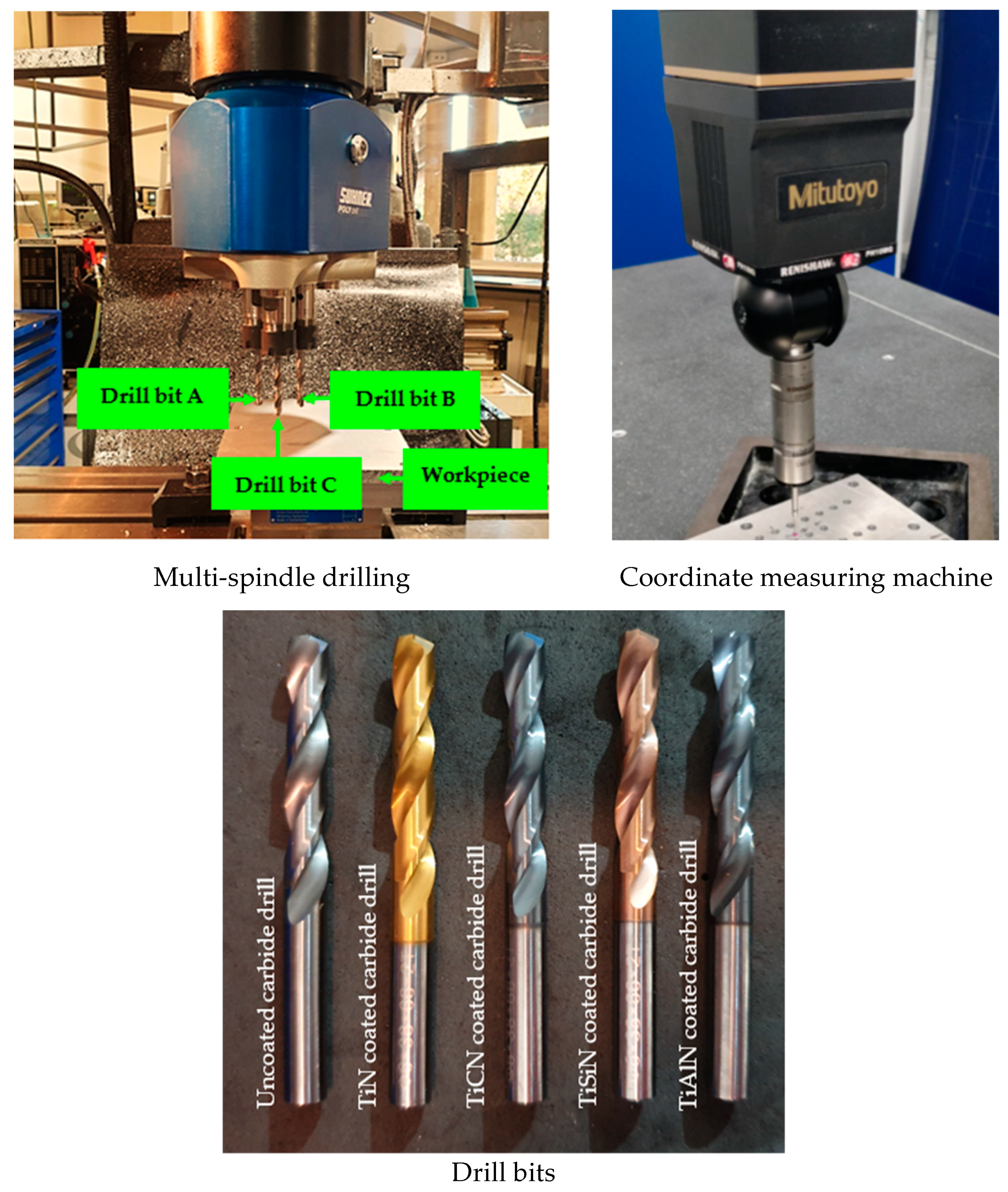
2. Materials and Methods

In this study, Al2024 plate with a size of 200 × 150 mm2 and a thickness of 10 mm was used as the workpiece material for creating holes. The drill bits used were an uncoated and (TiN, TiCN, TiAlN, and TiSiN) coated carbide twist drill with a 6 mm diameter [26]. The selection of coatings was based on their excellent hardness and high thermal and oxidation resistance that contributes to the improvement of holes [27,28]. Some of the properties of drill bits are given in Table 1.
The point angle and helix angle for all the studied drill bits were the same, and the geometries were chosen based on previous studies on one-shot drilling of Al2024 to create high-quality holes [31,32]. Additional details on the drill bits are provided in Table 2.
A type MH 30/13 adjustable multi-spindle drill head (SUHNER Inc., Lupfig, Switzerland) was used for multi-hole drilling. The multi-spindle head has three adjustable spindles that drill three holes simultaneously at the same cutting conditions for high productivity at a high rate without compromising the hole quality. First, a set of three uncoated drills were mounted on the multi-spindle drill head and then the same procedure was applied for TiN, TiCN, TiAlN, and TiSiN coated drills. Therefore, a total of 135 holes were created using all the drill bits to complete the experiments under dry conditions. The experimental setup is given in Figure 1.
A manual milling machine (model: 5KS, 5KV) was used to perform the drilling operations. The machine has the capacity of maximum spindle speed of 3450 rpm. Therefore, the values of spindle speeds used in this study were adjusted each time using a tachometer from low, medium, and high, corresponding to 1007, 2015, and 3025 rpm, respectively. The selected feeds were 0.04, 0.08, and 0.14 mm/rev, which were considered based on the available feed of the vertical milling machine.
After the drilling experiments, the geometric tolerances including the hole size, circularity, perpendicularity and cylindricity of holes were measured using a coordinate measuring machine (CMM,) type Mitutoyo Crysta-Apex S776, Renishaw, Gloucestershire, UK. A 2 mm diameter ruby stylus was used for the measurements. The measurement was taken 1 mm below the top region and 1 above the bottom region of the inside each hole, similar to the previous studies [33]. Finally, circles were generated using the maximum inscribed circle for each measurement.
A scan electron microscopy (model: Hitachi SU5000, Chiyoda, Japan) was used to examine the machined hole surface after the holes were cut in half.
Finally, the percentage contribution of drilling parameters on the studied hole quality parameters was determined using analysis of variance (ANOVA).

3. Results

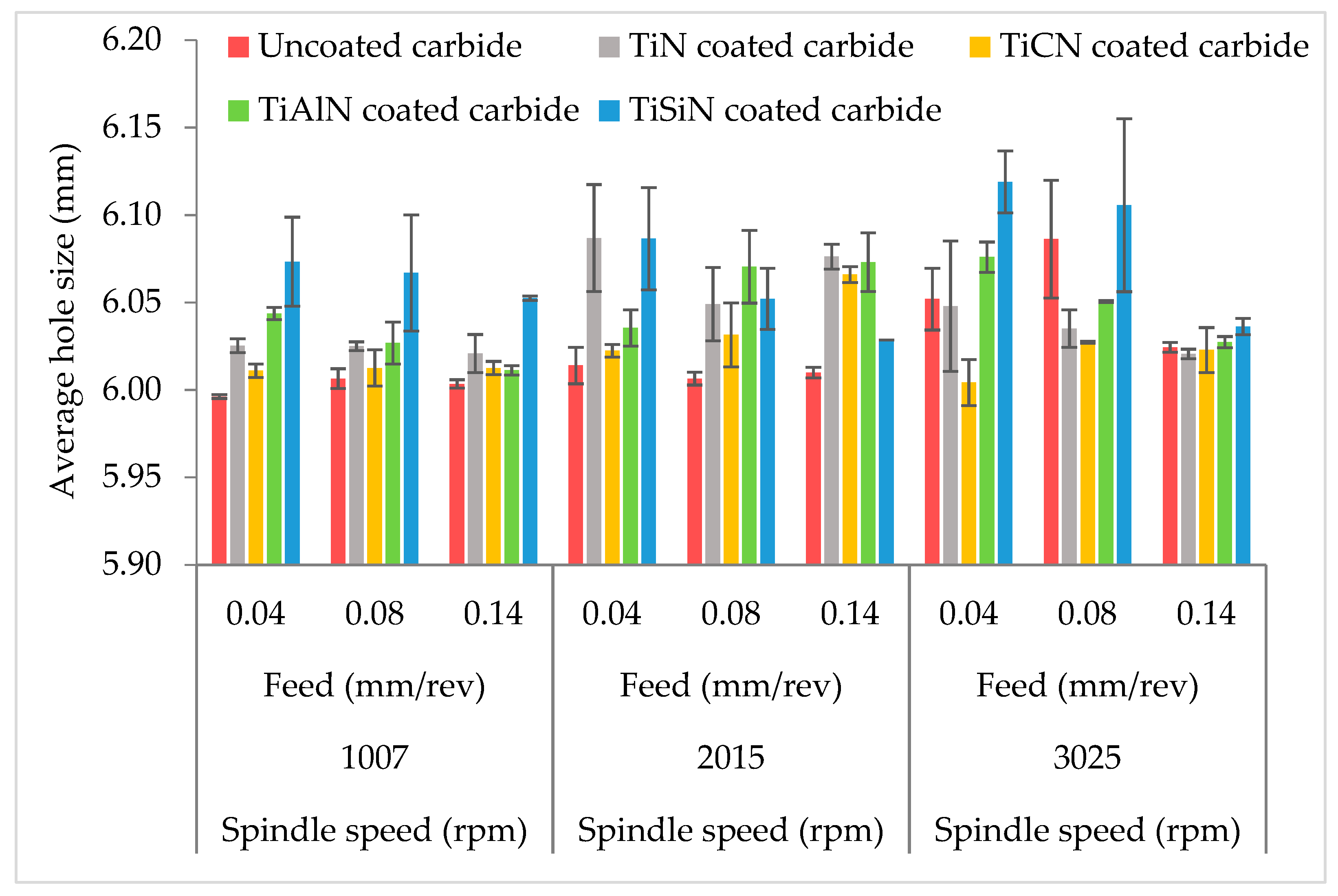
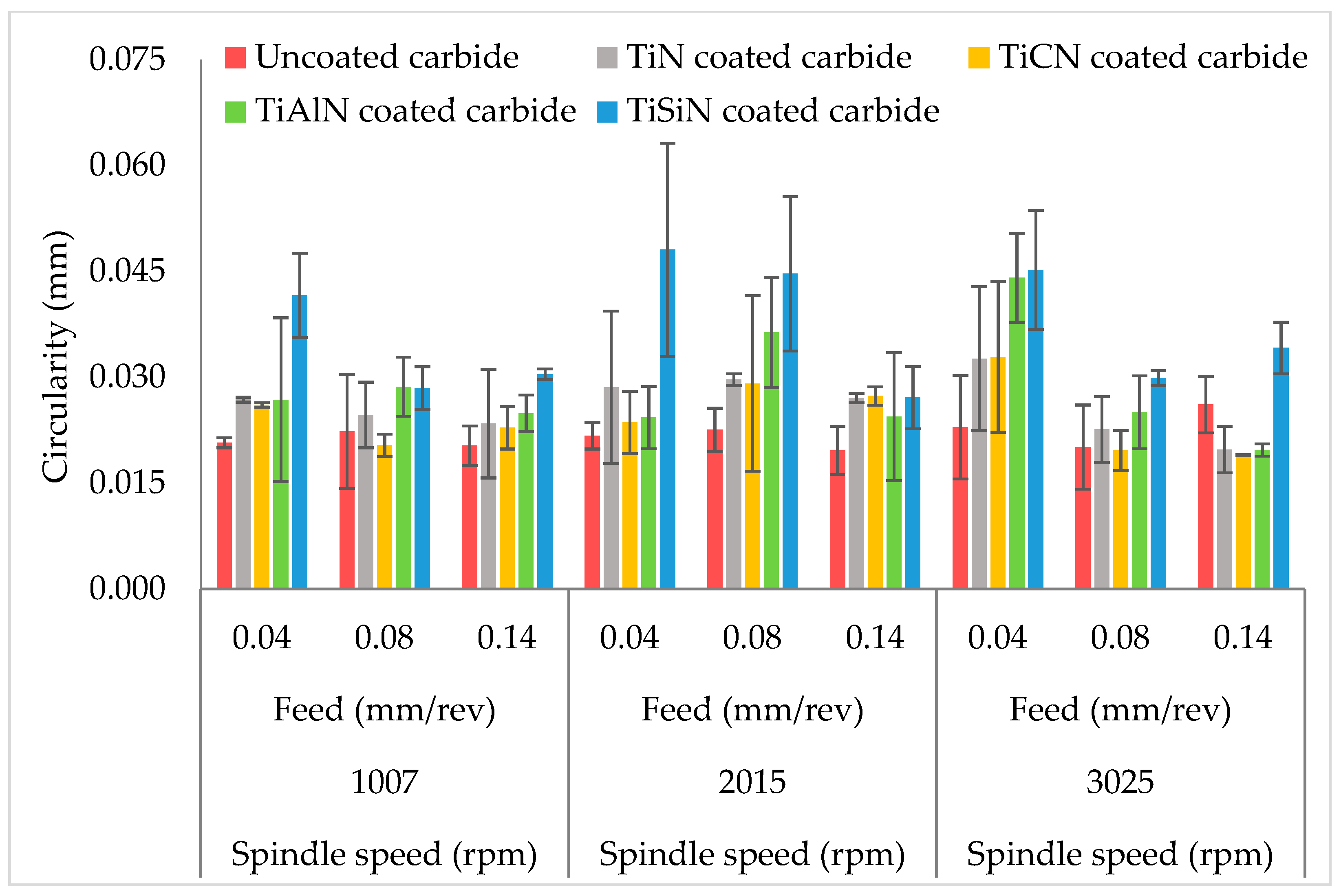
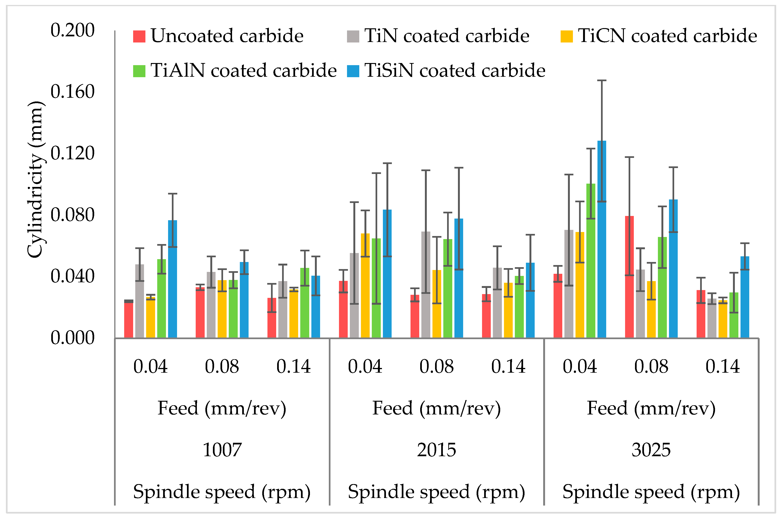
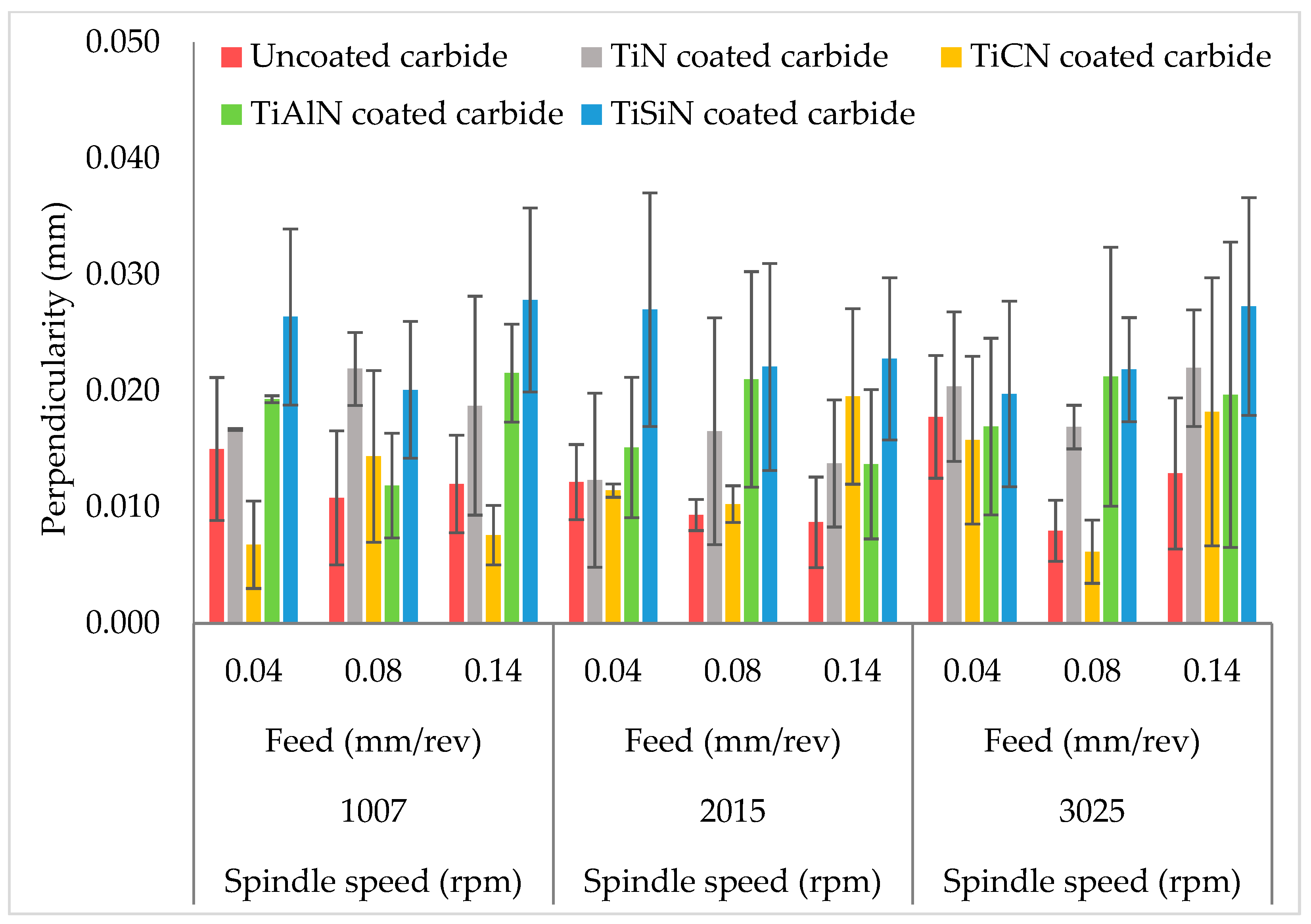
3.1. Hole Size, Circularity, Cylindricity and Perpendicularity

Diametric error is the deviation of holes from the nominal size for achieving high-quality holes [34]. The investigation of hole size in any manufacturing industry is essential when the drilling process is performed under dry conditions since a higher cutting temperature is expected due to the increased friction at the tool–chip interface [35]. Figure 2 shows the deviation of the hole from the nominal size (6 mm) for the uncoated and coated carbide drills (i.e., TiN, TiCN, TiAlN, and TiSiN). The results showed that the maximum hole deviations were found in holes drilled using TiSiN coated carbide drills, followed by TiAlN and TiN, irrespective of the drilling parameters. Interestingly, holes drilled using uncoated carbide drills showed the least deviation of hole size except for TiN and TiCN at high spindle speed. The TiAlN and TiSiN coated carbide drill gave the highest hole deviation under the selected cutting parameters during the multi-hole simultaneous drilling process.
In aerospace industries, stringent geometric tolerances are required where most of the metallic structures should be as relaxed as ±30 microns and as tight as ±12 microns [36]. Furthermore, according to the cutting tool manufacturers, the acceptable hole size can range between ±20 and ±40 microns for aluminum alloys [37]. Table 3 shows the variation of hole size from the uncoated and coated carbide drills, which concludes that hole size investigated in this study falls within the limits of the hole tolerance in the aerospace industry, except for the TiAlN and TiSiN.
Figure 2 also shows that generally, the hole size increased with the increase in the spindle speed. The tool coating showed the highest impact on the hole size with a percentage contribution of 33.97%, following the spindle speed and feed with a contribution of 12.72% and 4.12%, respectively. Another significant factor is the two-way interaction of spindle speed and tool coating, with a contribution of 20.23%.
Another essential characteristic of hole quality is circularity. Circularity or roundness is the radial difference between the concentric circles that must be minimized [38]. Figure 3 showed that the uncoated carbide drill resulted in the lowest circularity error, except when drilling at the highest spindle speed. In the case of carbide coated drills, the TiCN coated carbide drill performed better by giving minimum circularity error following the TiN, TiAlN, and TiSiN. The minimum circularity error obtained in this result was 0.0197 mm for uncoated carbide drills, 0.0198 mm for TiN, 0.0190 mm for TiCN, 0.0197 mm for TiAlN, and 0.0271 mm for TiSiN. Figure 3 also shows that the circularity was also affected by the cutting parameters. Overall, the circularity error increased with the increase in spindle speed. However, in some cases, the circularity error decreased with the increase in the feed, especially at a high feed of 0.14 mm/rev. The highest influence on circularity error was due to the tool coating, as evident from Table 4 with a percentage contribution of 46.37%, followed by 13.77% significance of feed. The contribution of spindle speed was insignificant because ANOVA was run with a confidence interval of 95%. Therefore, p values more than 0.05 in the ANOVA result were considered insignificant [9].
Cylindricity is the three-dimensional version of circularity and refers to an object not only being round, but also straight along its axis [39]. It is defined as the radial difference between two concentric cylinders with the actual cylinder (workpiece) contained within them [38]. Perpendicularity shows the orientation of a hole axis relative to a specified datum where the tolerance zone is represented by a cylinder located at the basic location [40]. Also, the assessment of perpendicularity error is essential for bolted structure joints because holes need to be parallel to the joint’s surface to achieve a better contact area between the outer edges of the nut and the bolt heads with the workpiece to avoid significant stress concentrations and fatigue cracks due to poor connecting holes [40].
The cylindricity and perpendicularity of each hole are given in Figure 4 and Figure 5, respectively. The result indicates that under most of the cutting parameters used in this study, the uncoated carbide drill performed better by giving minimum cylindricity error. The TiSiN gave the highest cylindricity error following the TiAlN and TiN. Similarly, the lowest perpendicularity error was obtained using TiCN drill bits following the uncoated carbide drill bits, TiN, TiAlN, and TiSiN coated drills. The ANOVA results given in Table 4 for the cylindricity indicate that the tool coating had the highest contribution of 30.32% in the investigated range of cutting parameters. On the other hand, the spindle speed and feed had a significance of only 12.09% and 24.22%, respectively. In general, the cylindricity increased with the increase in the spindle speed. The tool coating also had a significant impact on the perpendicularity with a contribution of 61.29%. However, no significant effect of spindle speed, feed, and other interaction was found on the perpendicularity error.

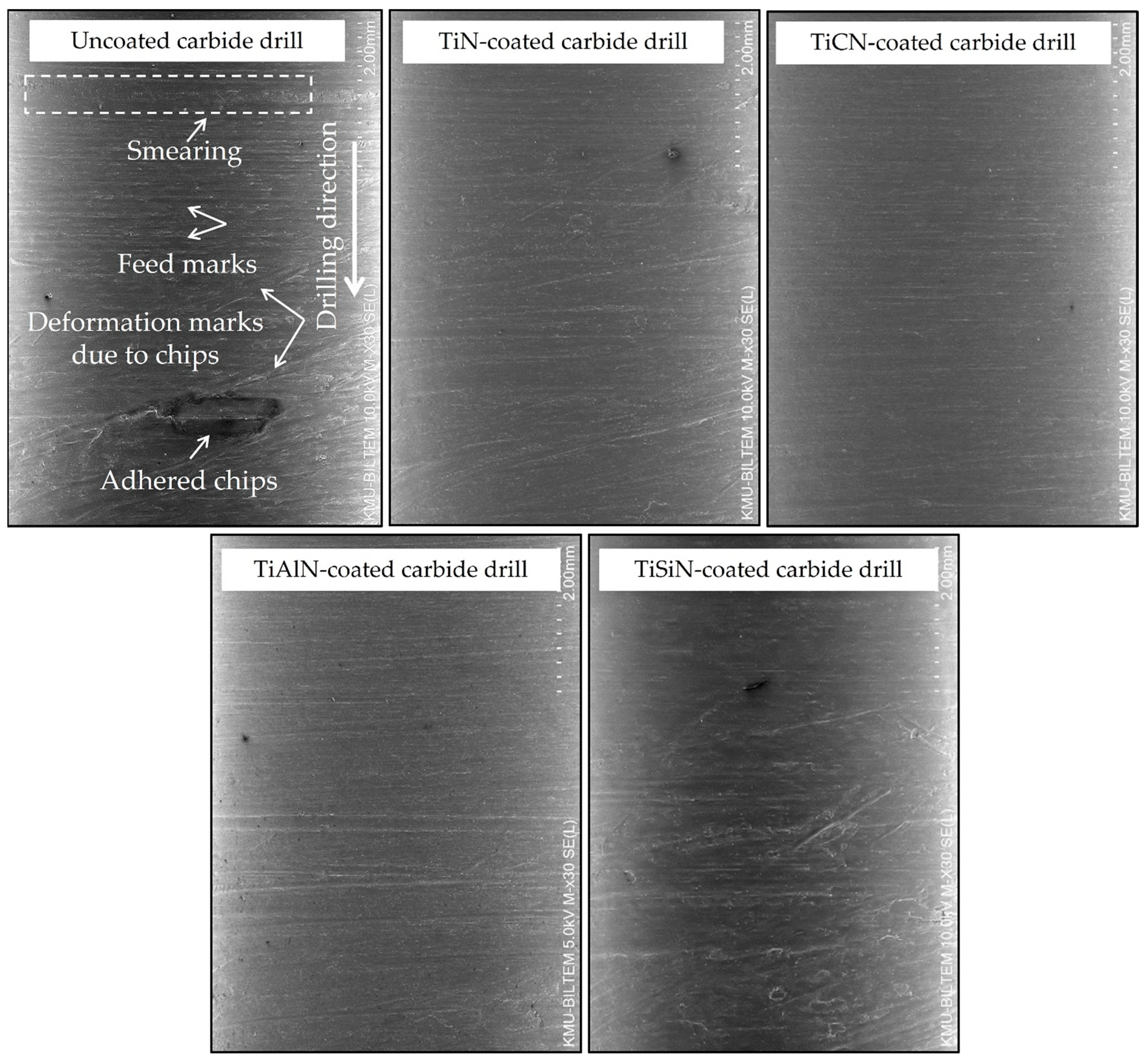
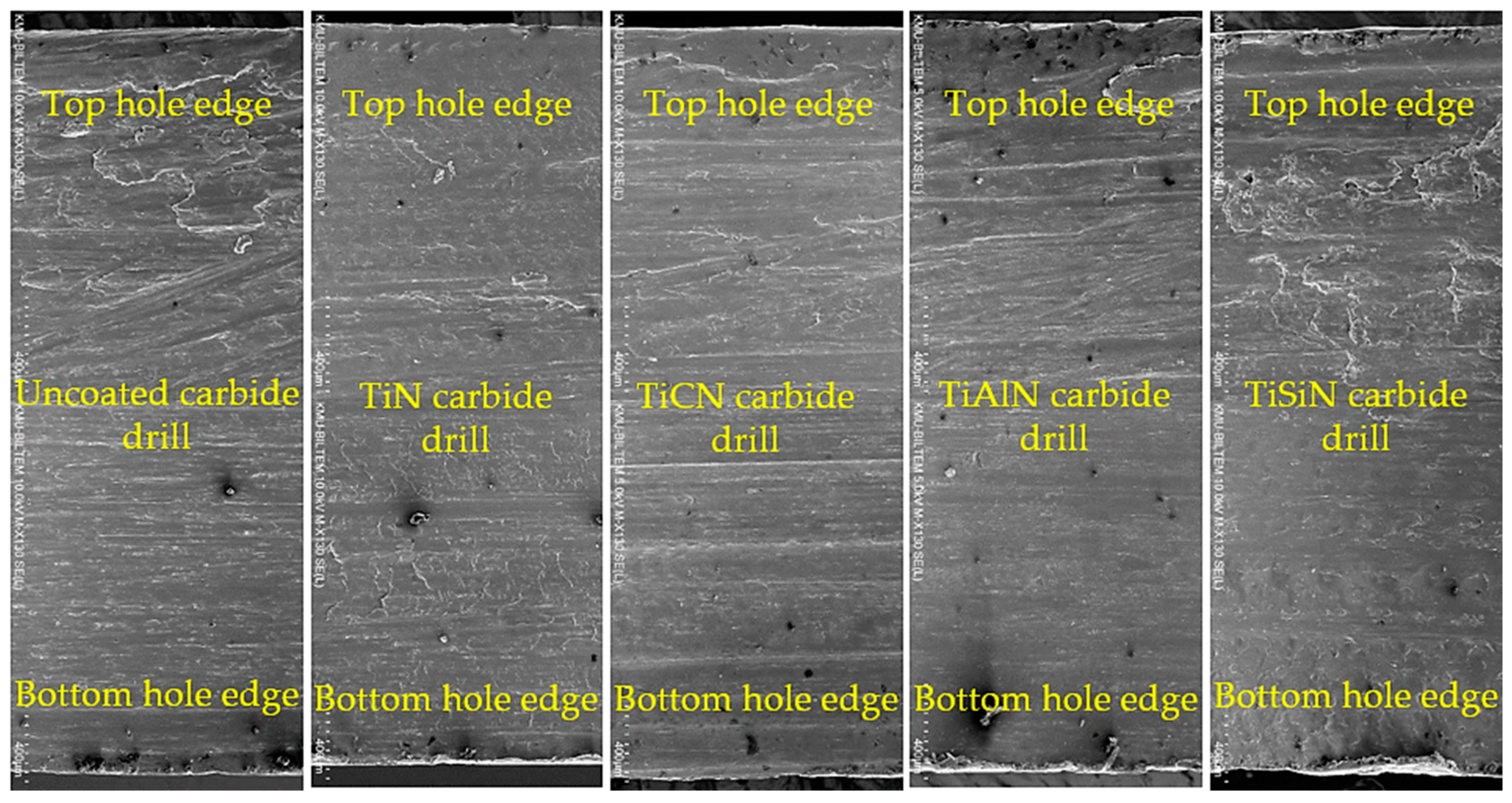
3.2. Surface Damage Analysis

The functional performance of any structural part in a manufacturing industry highly depends on its surface quality. Therefore, the analysis of surface defects is crucial after any material-removing process for improving the surface quality of manufacturing components [41]. Figure 6 shows the scanning electron microscopy (SEM) images of the borehole surface of Al2024 produced by five different carbide drills under different cutting conditions. In general, the SEM micrographs showed the surface defects such as smearing, which is a thin layer of deformation at the hole’s surface that results from the continuous rubbing of the cutting tool with the borehole walls and occurs due to the ductility of the material [42]. According to Liang et al. [41], the rise in spindle speed and feed rate increased the temperature, which leads to the formation of smearing. Smearing also results in random chip debris and adhesive chips on the hole surface during machining. Other forms of damage observed include feed marks and deformation marks due to the collision of evacuated chips through the drill flutes with the borehole walls and chip adhesion. However, it is worth noting that no visible cracks were observed on the surface of all holes investigated during the multi-spindle drilling process. Figure 6 also shows that the smoothest hole surface with the least observable defects were for those drilled using the TiCN coated tools, especially at a high spindle speed of 3025 rpm following the TiN-coated drill. However, it appears that the uncoated carbide drill gave better hole surface, which was possible only at low cutting parameters. It is interesting to note that the damage and distortion of the hole surface were seen more in the hole surface produced by the TiSiN-coated carbide drill bits following TiAlN carbide drills under all the examined cutting conditions.
Similarly, Figure 7 shows the entry and exit side of the hole edges at the high spindle speed of 3025 rpm. The results revealed that the edges of the hole at the top were more regular and uniform than at the bottom of the holes. Therefore, the holes produced more deterioration at the exit side. Moreover, the holes produced by the TiSiN drills showed an irregular appearance at both sides of the hole edges following the TiAlN. The hole edges at the entry and exit holes seem to be the same; however, a closer examination revealed that the TiCN gave better results, followed by uncoated carbide and TiN-coated drills. The results also showed that the surface defects were more affected by the spindle speed than feed. However, in the case of top-and bottom-hole edges, the feed was more influenced than the spindle speed. A detailed discussion of all the results is presented in the following section.

4. Discussion

This section discusses the surface defects and the geometric tolerances of a hole in multi-spindle simultaneous drilling of Al2024. The study suggested that generally, the hole size, circularity, and cylindricity increased with the increase in the spindle speed with a varying percentage contribution from the ANOVA results. It is speculated that the high drilling vibration and high velocity of chip flow due to high spindle speed might have affected the geometric hole tolerance [35,43]. Furthermore, machining temperature at the tool–chip interface is expected to increase with the increase of spindle speed, especially during the dry drilling process due to increased friction. The rise in temperature at the tool–chip interface causes softening of the workpiece materials, and hence the strength of the material decreases against the tool vibration [44]. Although a slower spindle speed compromises productivity, however, a multi-spindle drilling process can compensate for the slower drilling process since it can produce several holes simultaneously, thus providing a balance between productivity and improved hole quality.
Furthermore, the feed has a varying effect on the hole quality. However, it is seen that at the high feed of 0.14 mm/rev, the hole size was less deviated from the nominal size, which was 6 mm in this study, and gave less circularity and cylindricity error. This is in agreement with the machinery’s handbook, where it was recommended that for the twist drills with sizes ranging from 3.175 to 6.35 (mm), the recommended feed range is 0.05–0.15 (mm/rev), and the higher feed should be used for materials like brass or aluminum for better results [45]. In addition, the hole deterioration due to the increase in the feed is likely due to the higher thrust force [46,47]. However, the spindle speed and the feed did not affect the perpendicularity error, as evident from the ANOVA result in Table 4. Furthermore, the variations in the measurement of the hole quality due to an increase in the spindle speed and feed might be due to some other parameters such as vibration, tool deflection, and machine dynamics [37], which were not part of this study and are recommended as future investigations. Additionally, according to Uddin et al. [48], during CMM measurement, it is possible that some debris potentially remained on the surface of the hole walls even after cleaning the hole surface, which might cause such variations in the results.
However, the main objective of the current study was to evaluate the effect of cutting tool coating on the hole geometrical tolerances, and it is worth noting that hole quality is affected by the tool coating selected under all the examined cutting parameters, as evident from the ANOVA results. Among all the drills selected in this study, the uncoated carbide drill performed better by giving high-quality holes at lower cutting parameters. This could be because the cutting forces and temperature at the tool–chip interface were not significantly high when drilling at low cutting parameters. Therefore, the hole quality was not affected by the uncoated carbide drills [31]. Consequently, it can be concluded that under the selected cutting parameters, the coated carbide drills did not improve the machined hole quality, and only the TiCN carbide coated drills can be said to produce a better hole quality at the highest spindle speed used in the current study, followed by the TiN, as evident from the SEM images in Figure 6. However, the TiAlN and TiSiN coated carbide drills did not give high-quality holes under the examined cutting parameters in this study.
Previously, it was investigated by Nouari et al. [32] that coated tools performed better at high spindle speed by providing thermal barriers at high temperatures that reduce the diffusion process during dry drilling of Al2024. However, in this study, only a TiCN-carbide drill performed better by producing high-quality at high spindle speed, which might be due to the high hardness and low coefficient of friction, as given in Table 1 [27]. In addition, according to Hosokawa et al. [49], the higher hardness of the TiCN coated drill bits is due to their carbon contents, which makes them more resistant to adhesion, hence performing somewhat more effectively at high cutting parameters. In addition, previous studies have also shown that the high hardness of TiCN than the TiN coated tools provided better tool life [50].
The TiAlN was also not recommended for high-quality holes during this study. It was reported that aluminum-based coatings tend to stick to the workpiece surface during the machining of aluminum and its alloys. This is because they have abrasive properties that contribute to further adhesion and, consequently, the progression of BUE [51]. However, fewer surface defects were observed in the holes drilled with the TiAlN than TiSiN coated drills. The reason for low-quality holes and high surface defects from TiSiN, despite its high hardness, is attributed to its limited adhesion properties than TiAlN, resulting in a reduction in tool performance [52]. Furthermore, TiAlN has a lower coefficient of friction than the TiSiN coated drills [27], and it is reported in the literature that a low coefficient of friction tends to reduce the BUE [53].
The SEM images in Figure 7 also illustrate that the surface finish of both the top and bottom edges were affected; however, it seems that the exit side of the holes was more deteriorated with the irregular surface than at the entry. Indeed, according to Kurt et al. [35], when the drill bit in is contact with the workpiece, the vibration tends to have maximum values. In addition, as the drill advances through the hole toward its exit, the workpiece material becomes more plastically deformed, and its strength is reduced [54]. The rise in workpiece temperature due to the drilling process was lower at its upper part, and thus, there were fewer chances of inaccuracies and surface defects [55]. Hence, the workpiece material becomes prone to friction in this region and cannot sustain a further plastic deformation under further drilling loads [56].

5. Conclusions

The current study investigated the influence of uncoated and coated carbide drills on the hole dimensional tolerances and the microstructural examinations of holes drilled in Al2024 aluminum alloy during the multi-spindle simultaneous drilling process. Four types of coated tools (TiN, TiCN, TiAlN, and TiSiN) were used to drill holes in the workpiece material under dry conditions. The following can be concluded from this study:
  • The surface damage found on the inner hole surface was metal debris adhesion, smeared material, and feed marks.
  • Uncoated-carbide drills performed better at low cutting parameters, yielded high-quality holes, and fewer defects on the inner hole surface.
  • TiCN-coated carbide drills gave better hole accuracy and less damage in the inner hole wall surface at the highest spindle speed, followed by the TiN.
  • The worst surface finish with irregular patterns around the top and bottom of the hole edges and most oversized holes were obtained by TiSiN-coated carbide drills following the TiAlN.
  • Overall, the uncoated carbide drills outperformed better at low cutting parameters, while the TiN coated drills were recommended for high-quality holes at high cutting parameters selected in this study.
  • Regarding cutting parameters, the hole size, circularity, and cylindricity increased with the increase in the spindle speed with a varying percentage contribution from the ANOVA results. The feed had a varying effect on the hole quality; however, in some cases, it was seen that there was less error in hole size, circularity, and cylindricity error at the high feed. However, further investigation at high cutting parameters is required to better understand the performance of tool coatings at a wider range of cutting parameters using a multi-spindle simultaneous drilling process, which will be the scope of a future study.

Author Contributions

Conceptualization, M.A., and M.T.-R.; Methodology, M.A., M.T.-R., and K.G.; Validation, M.A., M.T.-R., K.G., A.V., U.K., A.D., and W.K.; Investigation, M.A., K.G., U.K., A.D., and W.K.; Writing—original draft preparation, M.A.; Writing—review and editing, M.T.-R., K.G., U.K., and A.V. All authors have read and agreed to the published version of the manuscript.

Funding

This research received no external funding.

Institutional Review Board Statement

Not applicable.

Informed Consent Statement

Not applicable.

Data Availability Statement

The data presented in this study are available on request.

Acknowledgments

The first author would like to thank Edith Cowan University for the awarded (ECU-HDR) higher degree research scholarship.

Conflicts of Interest

The authors declare no conflict of interest.

References

  1. Aamir, M.; Tolouei-Rad, M.; Giasin, K.; Nosrati, A. Recent advances in drilling of carbon fiber–reinforced polymers for aerospace applications: A review. Int. J. Adv. Manuf. Technol. 2019, 105, 2289–2308. [Google Scholar] [CrossRef]
  2. Habib, N.; Sharif, A.; Hussain, A.; Aamir, M.; Giasin, K.; Pimenov, D.Y.; Ali, U. Analysis of Hole Quality and Chips Formation in the Dry Drilling Process of Al7075-T6. Metals 2021, 11, 891. [Google Scholar] [CrossRef]
  3. Efstathiou, C.; Vakondios, D.; Lyronis, A.; Sofiakis, K.; Antoniadis, A. Finite Element Modeling and Experimental Study of Burr Formation in Drilling Processes. In Proceedings of the ASME 2016 International Mechanical Engineering Congress and Exposition, Phoenix, AZ, USA, 13–17 November 2016; p. 9. [Google Scholar]
  4. Aamir, M.; Giasin, K.; Tolouei-Rad, M.; Vafadar, A. A review: Drilling performance and hole quality of aluminium alloys for aerospace applications. J. Mater. Res. Technol. 2020, 9, 12484–12500. [Google Scholar] [CrossRef]
  5. Aamir, M.; Tu, S.; Giasin, K.; Tolouei-Rad, M. Multi-hole simultaneous drilling of aluminium alloy: A preliminary study and evaluation against one-shot drilling process. J. Mater. Res. Technol. 2020, 9, 3994–4006. [Google Scholar] [CrossRef]
  6. Rivero, A.; Aramendi, G.; Herranz, S.; de Lacalle, L.L. An experimental investigation of the effect of coatings and cutting parameters on the dry drilling performance of aluminium alloys. Int. J. Adv. Manuf. Technol. 2006, 28, 1–11. [Google Scholar] [CrossRef]
  7. Iqbal, A.; Zhao, G.; Zaini, J.; Gupta, M.K.; Jamil, M.; He, N.; Nauman, M.M.; Mikolajczyk, T.; Pimenov, D.Y. Between-the-Holes Cryogenic Cooling of the Tool in Hole-Making of Ti-6Al-4V and CFRP. Materials 2021, 14, 795. [Google Scholar] [CrossRef] [PubMed]
  8. Haan, D.; Batzer, S.; Olson, W.; Sutherland, J. An experimental study of cutting fluid effects in drilling. J. Mater. Process. Technol. 1997, 71, 305–313. [Google Scholar] [CrossRef]
  9. Aamir, M.; Tolouei-Rad, M.; Giasin, K.; Vafadar, A. Feasibility of tool configuration and the effect of tool material, and tool geometry in multi-hole simultaneous drilling of Al2024. Int. J. Adv. Manuf. Technol. 2020, 111, 861–879. [Google Scholar] [CrossRef]
  10. Vafadar, A.; Hayward, K.; Tolouei-Rad, M. Drilling reconfigurable machine tool selection and process parameters optimization as a function of product demand. J. Manuf. Syst. 2017, 45, 58–69. [Google Scholar] [CrossRef] [Green Version]
  11. Hanif, M.I.; Aamir, M.; Ahmed, N.; Maqsood, S.; Muhammad, R.; Akhtar, R.; Hussain, I. Optimization of facing process by indigenously developed force dynamometer. Int. J. Adv. Manuf. Technol. 2019, 100, 1893–1905. [Google Scholar] [CrossRef]
  12. Tönshoff, H.; Spintig, W.; König, W.; Neises, A. Machining of holes developments in drilling technology. CIRP Ann. 1994, 43, 551–561. [Google Scholar] [CrossRef]
  13. Sinmazçelik, T.; Avcu, E.; Bora, M.Ö.; Çoban, O. A review: Fibre metal laminates, background, bonding types and applied test methods. Mater. Des. 2011, 32, 3671–3685. [Google Scholar] [CrossRef]
  14. Sahu, S. Performance Evaluation of Uncoated and Multi Layer Tin Coated Carbide Tool in Hard Turning. Master’s Thesis, National Institute of Technology, Rourkela, India, 2012. [Google Scholar]
  15. Armarego, E.; Verezub, S.; Samaranayake, P. The effect of coatings on the cutting process, friction, forces and predictive cutting models in machining operations. Proc. Inst. Mech. Eng. Part B J. Eng. Manuf. 2002, 216, 347–356. [Google Scholar] [CrossRef]
  16. Haron, C.C.; Ginting, A.; Goh, J. Wear of coated and uncoated carbides in turning tool steel. J. Mater. Process. Technol. 2001, 116, 49–54. [Google Scholar] [CrossRef]
  17. Tolouei-Rad, M.; Aamir, M. Analysis of the Performance of Drilling Operations for Improving Productivity. In Drilling; Tolouei-Rad, M., Ed.; IntechOpen: London, UK, 2021; Available online: https://www.intechopen.com/online-first/analysis-of-the-performance-of-drilling-operations-for-improving-productivity (accessed on 18 August 2020).
  18. Aamir, M.; Tu, S.; Tolouei-Rad, M.; Giasin, K.; Vafadar, A. Optimization and modeling of process parameters in multi-hole simultaneous drilling using taguchi method and fuzzy logic approach. Materials 2020, 13, 680. [Google Scholar] [CrossRef] [Green Version]
  19. Vafadar, A.; Tolouei-Rad, M.; Hayward, K. An integrated model to use drilling modular machine tools. Int. J. Adv. Manuf. Technol. 2019, 102, 2387–2397. [Google Scholar] [CrossRef]
  20. Tolouei-Rad, M. Intelligent analysis of utilization of special purpose machines for drilling operations. In Intelligent Systems; Koleshko, V.M., Ed.; InTech: Croatia, 2012; pp. 297–320. ISBN 978-953-51-0054-6. Available online: http://www.intechopen.com/books/intelligent-systems/intelligent-analysis-of-utilization-of-special-purposemachines-for-drilling-operations (accessed on 18 August 2020).
  21. Tolouei-Rad, M. An efficient algorithm for automatic machining sequence planning in milling operations. Int. J. Prod. Res. 2003, 41, 4115–4131. [Google Scholar] [CrossRef]
  22. Sun, D.; Lemoine, P.; Keys, D.; Doyle, P.; Malinov, S.; Zhao, Q.; Qin, X.; Jin, Y. Hole-making processes and their impacts on the microstructure and fatigue response of aircraft alloys. Int. J. Adv. Manuf. Technol. 2018, 94, 1719–1726. [Google Scholar] [CrossRef] [Green Version]
  23. Aamir, M.; Giasin, K.; Tolouei-Rad, M.; Ud Din, I.; Hanif, M.I.; Kuklu, U.; Pimenov, D.Y.; Ikhlaq, M. Effect of Cutting Parameters and Tool Geometry on the Performance Analysis of One-Shot Drilling Process of AA2024-T3. Metals 2021, 11, 854. [Google Scholar] [CrossRef]
  24. Dursun, T.; Soutis, C. Recent developments in advanced aircraft aluminium alloys. Mater. Des. (1980–2015) 2014, 56, 862–871. [Google Scholar] [CrossRef]
  25. Aamir, M.; Tolouei-Rad, M.; Giasin, K.; Vafadar, A. Machinability of Al2024, Al6061, and Al5083 alloys using multi-hole simultaneous drilling approach. J. Mater. Res. Technol. 2020, 9, 10991–11002. [Google Scholar] [CrossRef]
  26. Giasin, K.; Hodzic, A.; Phadnis, V.; Ayvar-Soberanis, S. Assessment of cutting forces and hole quality in drilling Al2024 aluminium alloy: Experimental and finite element study. Int. J. Adv. Manuf. Technol. 2016, 87, 2041–2061. [Google Scholar] [CrossRef]
  27. Statoncoating. Coatings for Cutting Tools. Available online: https://www.statoncoating.com/en/coatings/coatings-cutting-tools (accessed on 18 August 2020).
  28. Al-Tameemi, H.A.; Al-Dulaimi, T.; Awe, M.O.; Sharma, S.; Pimenov, D.Y.; Koklu, U.; Giasin, K. Evaluation of Cutting-Tool Coating on the Surface Roughness and Hole Dimensional Tolerances during Drilling of Al6061-T651 Alloy. Materials 2021, 14, 1783. [Google Scholar] [CrossRef] [PubMed]
  29. Engdahl, N.C. CVD Diamond Coated Rotating Tools for Composite Machining. In Proceedings of the Aerospace Manufacturing and Automated Fastening Conference and Exhibition, Toulouse, France, 12 September 2006; p. 9. [Google Scholar]
  30. Sheikh-Ahmad, J.Y. Machining of Polymer Composites; Springer: Boston, MA, USA, 2009; p. 315. [Google Scholar]
  31. Nouari, M.; List, G.; Girot, F.; Coupard, D. Experimental analysis and optimisation of tool wear in dry machining of aluminium alloys. Wear 2003, 255, 1359–1368. [Google Scholar] [CrossRef]
  32. Nouari, M.; List, G.; Girot, F.; Gehin, D. Effect of machining parameters and coating on wear mechanisms in dry drilling of aluminium alloys. Int. J. Mach. Tools Manuf. 2005, 45, 1436–1442. [Google Scholar] [CrossRef]
  33. Koklu, U.; Morkavuk, S.; Featherston, C.; Haddad, M.; Sanders, D.; Aamir, M.; Pimenov, D.Y.; Giasin, K. The effect of cryogenic machining of S2 glass fibre composite on the hole form and dimensional tolerances. Int. J. Adv. Manuf. Technol. 2021, 115, 125–140. [Google Scholar] [CrossRef]
  34. Aamir, M.; Tolouei-Rad, M.; Giasin, K.; Vafadar, A.; Koklu, U.; Keeble, W. Evaluation of the Surface Defects and Dimensional Tolerances in Multi-Hole Drilling of AA5083, AA6061, and AA2024. Appl. Sci. 2021, 11, 4285. [Google Scholar] [CrossRef]
  35. Kurt, M.; Kaynak, Y.; Bagci, E. Evaluation of drilled hole quality in Al 2024 alloy. Int. J. Adv. Manuf. Technol. 2008, 37, 1051–1060. [Google Scholar] [CrossRef]
  36. Giasin, K.; Hawxwell, J.; Sinke, J.; Dhakal, H.; Köklü, U.; Brousseau, E. The effect of cutting tool coating on the form and dimensional errors of machined holes in GLARE® fibre metal laminates. Int. J. Adv. Manuf. Technol. 2020, 107, 2817–2832. [Google Scholar] [CrossRef] [Green Version]
  37. Giasin, K.; Ayvar-Soberanis, S.; French, T.; Phadnis, V. 3D Finite Element Modelling of Cutting Forces in Drilling Fibre Metal Laminates and Experimental Hole Quality Analysis. Appl. Compos. Mater. 2017, 24, 113–137. [Google Scholar] [CrossRef] [Green Version]
  38. Souza, C.C.; Arencibia, R.V.; Costa, H.L.; Piratelli Filho, A. A contribution to the measurement of circularity and cylindricity deviations. In Proceedings of the ABCM Symposium Series in Mechatronics, Natal, RN, Brazil, 24–28 October 2011; p. 791. [Google Scholar]
  39. Selvarajan, L.; Narayanan, C.S.; Jeyapaul, R.; Manohar, M. Optimization of EDM process parameters in machining Si3N4–TiN conductive ceramic composites to improve form and orientation tolerances. Measurement 2016, 92, 114–129. [Google Scholar] [CrossRef]
  40. Giasin, K. The effect of drilling parameters, cooling technology, and fiber orientation on hole perpendicularity error in fiber metal laminates. Int. J. Adv. Manuf. Technol. 2018, 97, 4081–4099. [Google Scholar] [CrossRef] [Green Version]
  41. Liang, X.; Liu, Z.; Wang, B. State-of-the-art of surface integrity induced by tool wear effects in machining process of titanium and nickel alloys: A review. Measurement 2019, 132, 150–181. [Google Scholar] [CrossRef]
  42. Buehler. Solutions for Materials Preparation, Testing & Analysis: Don’t Smear It! Avoiding Surface Deformation in Polishing. Available online: https://metallography-matters.buehler.com/2018/09/17/dont-smear-it-avoiding-surface-deformation-in-polishing/#:~:text=To%20prevent%20smearing%2C%20it’s%20best,polishing%20surface%20can%20also%20help (accessed on 6 March 2021).
  43. Davoudinejad, A.; Ashrafi, S.A.; Hamzah, R.I.R.; Niazi, A. Experimental analysis of wear mechanism and tool life in dry drilling of Al2024. Adv. Mater. Res. 2012, 566, 217–221. [Google Scholar] [CrossRef]
  44. Sun, F.; Qu, S.; Su, F.; Deng, Z.; Li, X. Effect of micro-void on surface integrity after machining of Ti-6Al-4V workpieces prepared by HIP and forging. Int. J. Adv. Manuf. Technol. 2018, 98, 3167–3177. [Google Scholar] [CrossRef]
  45. Oberg, E. Machinery’s Handbook 29th Edition-Full Book; Industrial Press: New York, NY, USA, 2012. [Google Scholar]
  46. Aamir, M.; Tolouei-Rad, M.; Vafadar, A.; Raja, M.N.A.; Giasin, K. Performance Analysis of Multi-Spindle Drilling of Al2024 with TiN and TiCN Coated Drills Using Experimental and Artificial Neural Networks Technique. Appl. Sci. 2020, 10, 8633. [Google Scholar] [CrossRef]
  47. Aamir, M.; Tolouei-Rad, M.; Giasin, K. Multi-spindle drilling of Al2024 alloy and the effect of TiAlN and TiSiN-coated carbide drills for productivity improvement. Int. J. Adv. Manuf. Technol. 2021, 114, 3047–3056. [Google Scholar] [CrossRef]
  48. Uddin, M.; Basak, A.; Pramanik, A.; Singh, S.; Krolczyk, G.M.; Prakash, C. Evaluating hole quality in drilling of Al 6061 alloys. Materials 2018, 11, 2443. [Google Scholar] [CrossRef] [PubMed] [Green Version]
  49. Hosokawa, A.; Shimamura, K.; Ueda, T. Cutting characteristics of PVD-coated tools deposited by unbalanced magnetron sputtering method. CIRP Ann. 2012, 61, 95–98. [Google Scholar] [CrossRef]
  50. Jindal, P.; Santhanam, A.; Schleinkofer, U.; Shuster, A. Performance of PVD TiN, TiCN, and TiAlN coated cemented carbide tools in turning. Int. J. Refract. Met. Hard Mater. 1999, 17, 163–170. [Google Scholar] [CrossRef]
  51. Thorne, E.J. Cutting Tool Engineering-Aluminum Can Be Hard to Drill, Despite Its Easy Rep. Available online: https://www.ctemag.com/news/articles/aluminum-can-be-hard-drill-despite-its-easy-rep# (accessed on 17 August 2020).
  52. Bouzakis, K.-D.; Skordaris, G.; Gerardis, S.; Katirtzoglou, G.; Makrimallakis, S.; Pappa, M.; LilI, E.; M’Saoubi, R. Ambient and elevated temperature properties of TiN, TiAlN and TiSiN PVD films and their impact on the cutting performance of coated carbide tools. Surf. Coat. Technol. 2009, 204, 1061–1065. [Google Scholar] [CrossRef]
  53. Prengel, H.; Pfouts, W.; Santhanam, A. State of the art in hard coatings for carbide cutting tools. Surf. Coat. Technol. 1998, 102, 183–190. [Google Scholar] [CrossRef]
  54. Ko, S.-L.; Lee, J.-K. Analysis of burr formation in drilling with a new-concept drill. J. Mater. Process. Technol. 2001, 113, 392–398. [Google Scholar] [CrossRef]
  55. Shanmughasundaram, P.; Subramanian, R. Study of parametric optimization of burr formation in step drilling of eutectic Al–Si alloy–Gr composites. J. Mater. Res. Technol. 2014, 3, 150–157. [Google Scholar] [CrossRef] [Green Version]
  56. Mann, J.Y.; Milligan, I.S. Aircraft Fatigue: Design, Operational and Economic Aspects; Elsevier: Amsterdam, The Netherlands, 2013. [Google Scholar]
Figure 1. Experimental setup.
Metals 11 01103 g001
Figure 2. Deviation of holes from the nominal size for the uncoated and coated carbide drills.
Metals 11 01103 g002
Figure 3. Average circularity error.
Metals 11 01103 g003
Figure 4. Average cylindricity error.
Metals 11 01103 g004
Figure 5. Average perpendicularity error.
Metals 11 01103 g005
Figure 6. Inner hole surface of Al2024 using uncoated carbide and coated carbide drills at 3025 rpm and 0.14 mm/rev.
Metals 11 01103 g006
Figure 7. Top- and bottom-hole edges of the uncoated and coated carbide drills.
Metals 11 01103 g007
Table 1. Properties of cutting tools [27,29,30].
CoatingsOxidation Temperature (°C)Hardness (GPa)Friction Coefficient (µ)
Uncoated500260.4–0.6
TiN600230.4–0.5
TiCN400270.2
TiAlN700–800320.5–0.7
TiSiN1000350.6
Table 2. Description of the drill bit.
Specifications
TypeTwist drill
MaterialCarbide
CoatingsTiN, TiCN, TiAlN, and TiSiN
Number of flutes2
Drill diameter6 mm
Point angle140
Helix angle30°
Overall length66 mm
Table 3. Hole deviation from nominal size for the uncoated and coated carbide drills.
Hole Deviation (µm)
Spindle Speed (rpm)Feed (mm/rev)Uncoated CarbideTiNTiCNTiAlNTiSiN
10070.04425114473
10070.08625132767
10070.14321131152
20150.041487223686
20150.08649317052
20150.141076667329
30250.045248476119
30250.0886352751106
30250.142421232736
Table 4. Analysis of variance for hole quality.
SourceHole SizeCircularityCylindricityPerpendicularity
p ValueContributionp ValueContributionp ValueContributionp ValueContribution
Spindle speed0.00112.72%0.22.84%0.212.09%0.4521.95%
Feed0.0494.12%0.00313.77%0.00324.22%0.342.71%
Coating type033.97%046.37%030.32%061.29%
2-Way Interactions0.00640.15%0.19824.28%0.19824.49%0.81815.30%
Spindle speed × Feed0.0457.01%0.01813.09%0.0189.65%0.6932.64%
Spindle speed × Coating type0.00520.23%0.9262.31%0.9266.41%0.7136.25%
Feed × Coating type0.03512.91%0.2718.88%0.2718.43%0.76.41%
Error-9.04%-12.74%-8.88%-18.74%
Total-100.00%-100.00%-100.00%-100.00%
Publisher’s Note: MDPI stays neutral with regard to jurisdictional claims in published maps and institutional affiliations.

