Article

Brazing Tungsten/Tantalum/RAFM Steel Joint for DEMO by Fully Reduced Activation Brazing Alloy 48Ti-48Zr-4Be

1
Department of Materials Science, National Research Nuclear University MEPhI, 115409 Moscow, Russia
2
HSM Lab., Center for Energy Science and Technology, Skoltech, 121205 Moscow, Russia
*
Author to whom correspondence should be addressed.
Submission received: 10 August 2021 / Revised: 2 September 2021 / Accepted: 4 September 2021 / Published: 7 September 2021
(This article belongs to the Special Issue Tungsten and Tungsten Alloys)

Abstract

:
To create a DEMO reactor, it is necessary to develop high-quality technology to join tungsten with reduced-activation ferritic-martensitic (RAFM) steel (Rusfer, Eurofer, CLF-1, etc.). Difficulties arise in their direct connection due to the large difference in the coefficient of thermal expansion (CTE). To suppress the difference of CTE, intermediate interlayers are usually used, such as vanadium or tantalum, and brazing is a prospective technology to conduct the joining. The vast majority of works represent copper- or nickel-based brazing alloys, but their applicability is under significant discussion due to their activation properties. That is why, in this work, fully reduced activation 48Ti-48Zr-4Be wt.% brazing alloy was used. The following joint was made: Rusfer steel/48Ti-48Zr-4Be/Ta/48Ti-48Zr-4Be/W. The brazing was successfully carried out under a mode providing thermal heat treatment of Rusfer. Through EDS and EBSD analysis, the microstructure of the joint was determined. Shear strength of the as-joined composition was measured as 127 ± 20 MPa. The joint endured 200 thermocycles in the temperature range between 300–600 °C, but the fillet regions degraded.

1. Introduction

The DEMO fusion reactor is the next step towards an industrial thermonuclear power plant; projects of DEMO have been developed worldwide [1,2,3,4]. DEMO will focus on the production of electricity. It must demonstrate technological stability, safe power generation and reliable plant maintenance. When designing such a plant, it is necessary to take into account not only the physical requirements, but also the technical and technological constraints. Operating parameters in DEMO will be tougher than for ITER, so tungsten will be the Plasma Facing Material (PFM) for the First Wall, and Reduced Activation Ferritic Martensitic (RAFM) steel, such as Rusfer [5] or Eurofer [6], will be the construction material. Because of this fact, one urgent issue should be solved before construction—the production of a strong joint between tungsten and steel. However, direct connection is tough to achieve because of the big difference in coefficients of thermal expansion (CTE): (10.5–12.3) × 10−6K−1 for steel and (4.3–6.0) × 10−6K−1 for tungsten. A significant difference causes large residual stresses during cooling, and as a result can lead to the destruction of the joint [7,8]. Usually, intermediate layers are used to suppress a mismatch of CTE [9]. In DEMO, in order to relieve these stresses, it is proposed to use Nb [10], V [11], Ti [12], Cu [13], and Ta [14].
Nevertheless, it is necessary to select a reliable manufacturing technology. Several methods have been proposed: brazing with powder alloys [15], galvanic layers [16] and amorphous foils [17], or solid-state technologies for diffusion bonding [12,18,19]. Brazing is considered to be the most reliable technology, because it does not cause creep of the materials which are to be joined, and the cost is lower compared with hot isostatic pressing et al. According to ITER experience, it is also important to use a technology which allows local repair of damaged components during production [20]. However, until now no fully reduced activation brazing alloy has been used, or the strength of the joint was low [21]. Instead, scientists use nickel [17,22,23] or copper [11,24,25,26] brazing alloys, although these materials do not fully satisfy the requirement of reduced activation. To solve this problem, we are attempting to use a fully reduced activation composition, 48Ti-48Zr-4Be wt.%. This alloy has already been successfully used when brazing a self-passivating tungsten alloy [27].
Another advantage of brazing is the possibility of carrying out a simultaneous production process and the heat treatment of the materials to be joined. If a RAFM steel is used in a heat-treated state, a high joining temperature leads to α-γ transition during joining, so the steel is not martensitic anymore [28]. This means that the joining temperature is limited to 500 °C, because the properties of heat-treated RAFM steels significantly decrease after heating above 500 °C [29,30]. Not to spoil the steels’ microstructure during the joining process, brazing should be carried out simultaneously with the heat treatment of the steels.
In addition, it is very important to study mechanical strength, the exact microstructure of the brazed joints, and its changes under working conditions to assess the influence of the technological process, and the composition of the intermediate layers and filler alloys. The information obtained will be useful for the further optimization of the technology. All in all, a good joint for DEMO satisfies the requirement of reduced activation, can withstand heat loads and thermocycling during operation, and the manufacturing process does not spoil the microstructure of the materials to be joined.

2. Materials and Methods

2.1. Materials

In this work the following materials were used:
  • ITER-grade tungsten (W);
  • RAFM Rusfer EK-181 (Rusfer) steel with as-produced (Fe–12Cr–2W–V–Ta–B, wt %) (more information is presented elsewhere [31]);
  • pure tantalum (Ta). We used Ta as a compensating interlayer, as it was earlier shown that it effectively reduces stresses between W and steel [8];
  • 48Ti-48Zr-4Be wt.% (TiZr4Be) STEMET 1412 brazing alloy rapidly solidified into a ribbon of 70 μm thickness by applying spinning technology.
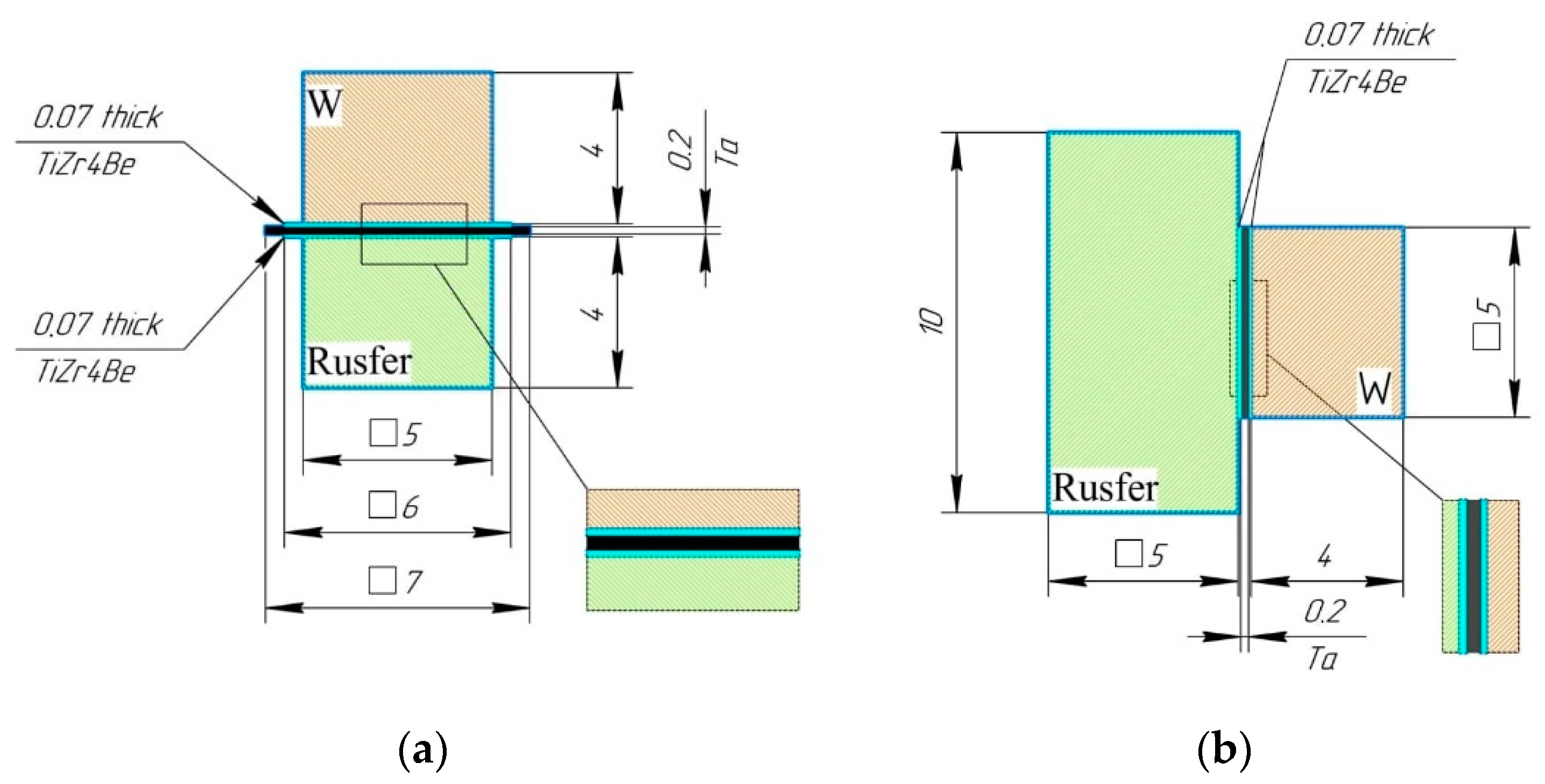
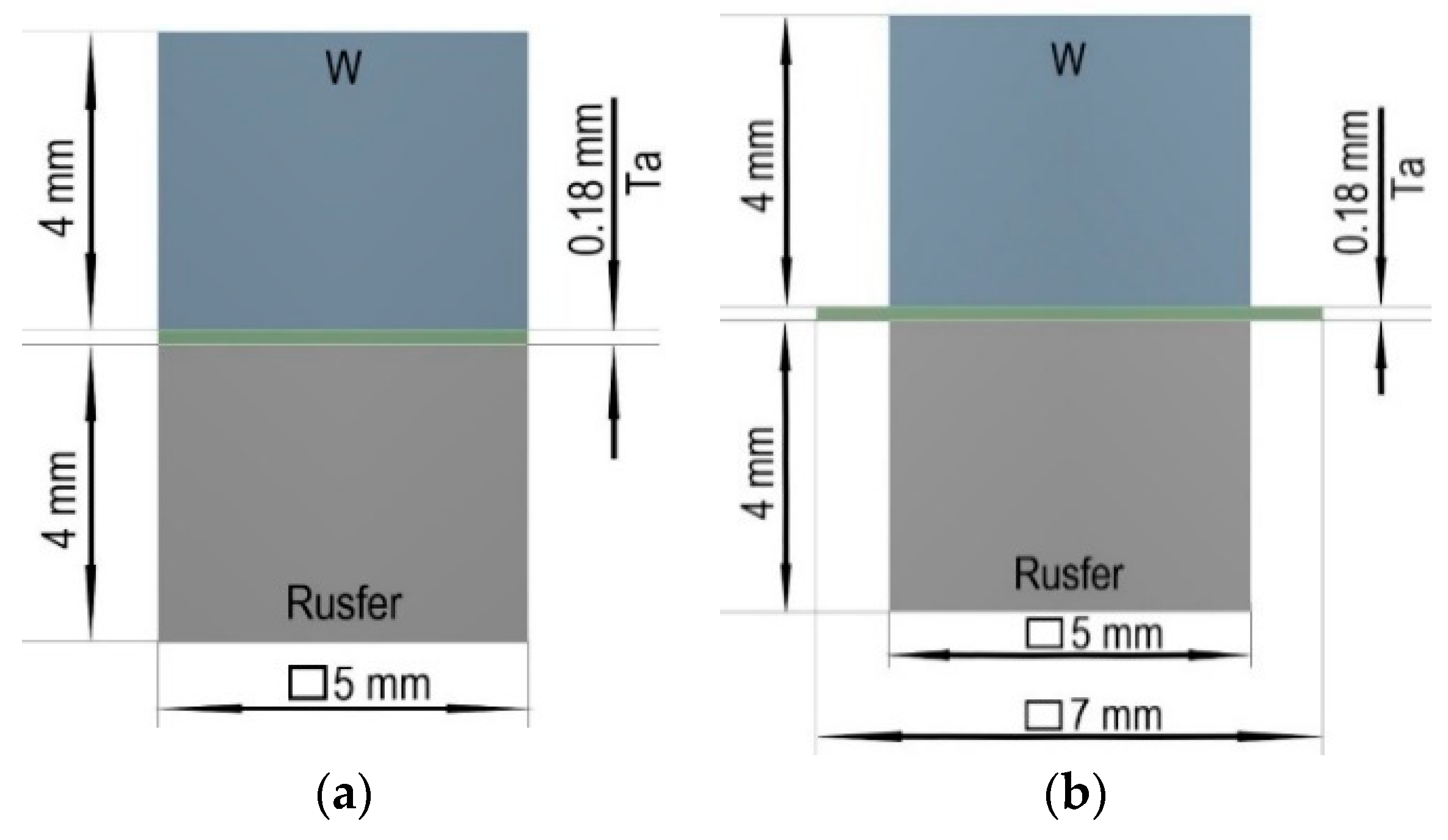
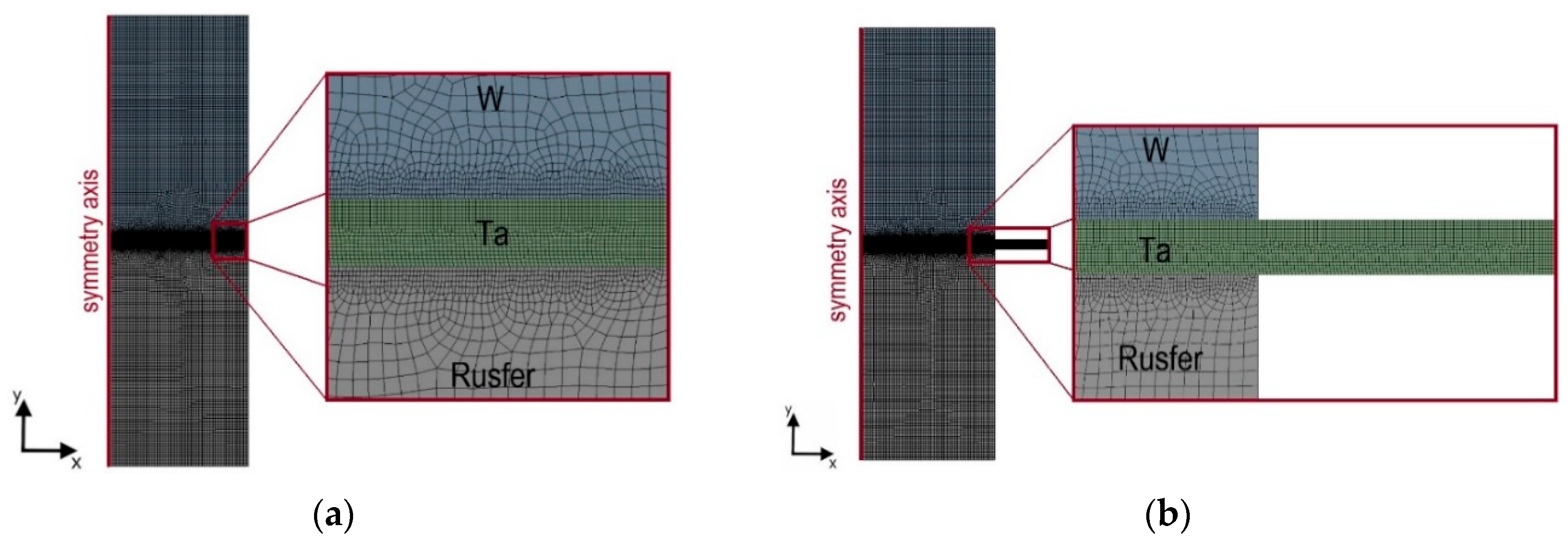
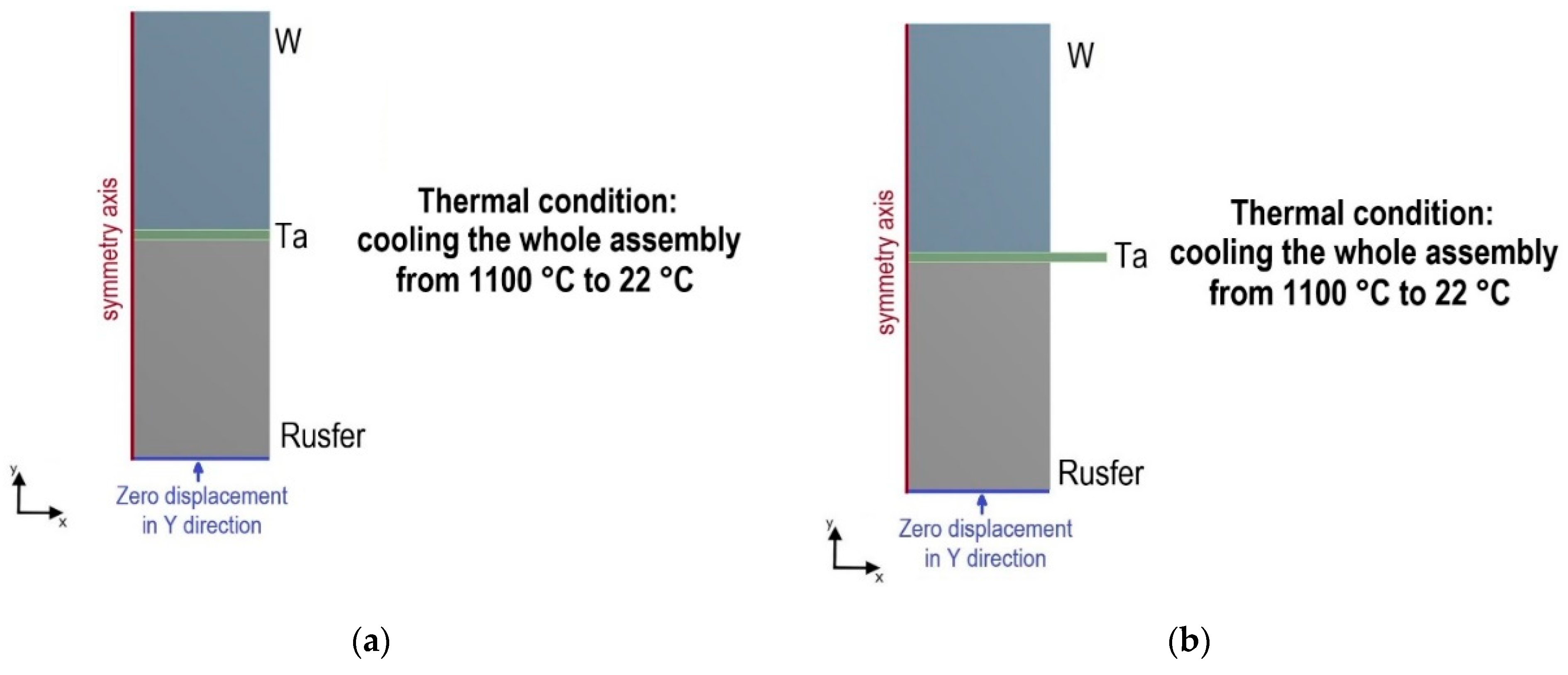
We manufactured the following joint: Rusfer/TiZr4Be/Ta/TiZr4Be/W.
STEMET brazing alloys are widely used in the nuclear, air and automotive industries [32,33,34,35,36]. TiZr4Be alloy has a good glass forming ability (GFA) produced by melt spinning [37], and a high GFA makes it possible to produce flexible foil by this spinning technology. The alloy has an amorphous state with a limited crystalline phase. The liquidus temperature of the alloy is close to 840 °C. The brazing alloy has been investigated in detail elsewhere [38].
Figure 1 shows the schematic view of the specimens in mm, for microstructural observation (a) and for shear tests (b).

2.2. Methods

We carried out brazing in a vacuum furnace (p < 10−5 mmHg). The specimens were fixed by a 200 g load that corresponded to 0.4 MPa. The gap between the base materials corresponded to the thickness of the brazing alloy. We used the brazing mode to arrive at thermal heat treatment of the steel: 1100 °C, 1 h + 720 °C 3 h [39], heating rate (Vh) for the first step 40 °C/min, cooling rate (Vc) 20 °C/min, for the second step Vh = 20 °C/min, Vc = 10 °C/min (we present the graph of the mode in [9]). This means that we carried out brazing simultaneously to the heat treatment of the steel.
The microstructure was investigated on the cross-sections of the brazed samples by MTI MM500T metallographic microscope (MTI Corporation, USA) and JEOL JSM-6610LV scanning electron microscope (SEM) with energy dispersive spectroscopy (EDS) INCA X-ACT (Jeol, Japan). Electron beam scattered diffraction (EBSD) analysis and ultra-high resolution photos were obtained by means of SEM TESCAN CLARA (Tescan, The Czech Republic) equipped with EBSD Oxford Instruments Nordlys Nano and EDS Oxford Instruments Ultim MAX 100 (Oxford Instruments, UK).
The specimens were prepared using a common metallographic procedure. For metallographic microscopy the samples were etched with 20% HNO3 + 20% HF + 60% glycerol solution, and the etching time was 1–3 s to identify the structure of the brazed seam and 20–30 s to identify the steel’s microstructure. Before EBSD analysis, the samples were etched with Technoorg Linda SEMPrep2 (Technoorg, Hungary).
Microhardness HV0.1 (load 0.9807 H, holding time 15 s) in the cross section of a brazed seam was measured by Vickers FM-800 (Future-Tech, Japan) equipment. Shear strength was measured by a Quasar50 (Galdabini, Switzerland) universal testing machine with 1 mm/min crosshead speed. The scheme of the shear test used is presented elsewhere [40]. We chose the shear test to ensure that the joint will fail throughout a seam. If the tensile test had been chosen, a failure could have occurred in the tungsten, because of its brittleness.
Thermocycling tests are very important while developing brazing processes, because phase transformation or a joint degradation can occur [41,42]. In this work we carried out the thermocycling test in an evacuated quartz ampoule with dynamic vacuum of p = 10−2 mmHg; to suppress oxygen concentration, titanium getter was also inserted into the ampoule. Samples were inserted into the ampoule and a thermocouple was as close as the samples. Previously we carried out thermocycling with cooling down by water [8,11] that was used to make express comparison of joints, but in this work we decided to carry out thermocycling closer to operating conditions. RAFM steel working temperature is limited to 550 °C, so we decided to heat up the joint to 600 °C, as the joints’ temperature can be higher. The ampoule was heated up in a tube furnace, and after achieving 600 °C the ampule was pulled out the furnace. Cooling lasted until 300 °C. We chose 300 °C to be close to water coolant temperature. During shut down, the First Wall will be cooled down to the coolant temperature [43]. Figure 2 shows the schematic image of the thermocycling regime. Four samples were subjected to the test, and integrity of the samples was observed every 50 cycles.
In Section 3.2.2. we conducted Fenite Elemental Analysis (FEA) of a specimen to optimize its geometry for further investigation. We calculated brazed joints W/Ta/Rusfer by means of FEA in ANSYS Workbench 18.2. The mechanical and physical properties of the materials, such as Young’s modulus (E), Poisson’s ratio ( ν ), yield strength ( σ 0.2 ), tangent modulus ( σ t a n ), stress-strain curves, and coefficient of thermal expansion ( α ), were taken from [8,44]. Figure 3 shows the resulting dimensions of the joints.
Figure 4 shows the generated mesh. The element size in the tantalum layer and near both contact regions is 0.01 mm. The element size in the tungsten and Rusfer layers is 0.05 mm.
We modeled the process of cooling the assemblies from a joining temperature of 1100 °C to room temperature of 22 °C. Figure 5 shows the boundary conditions for modeling.

3. Results and Discussion

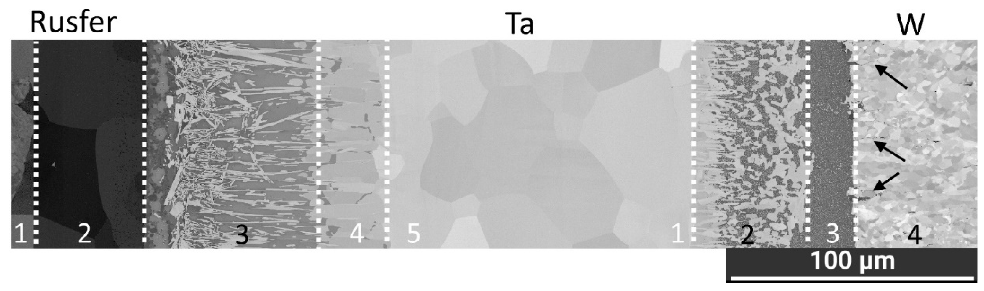
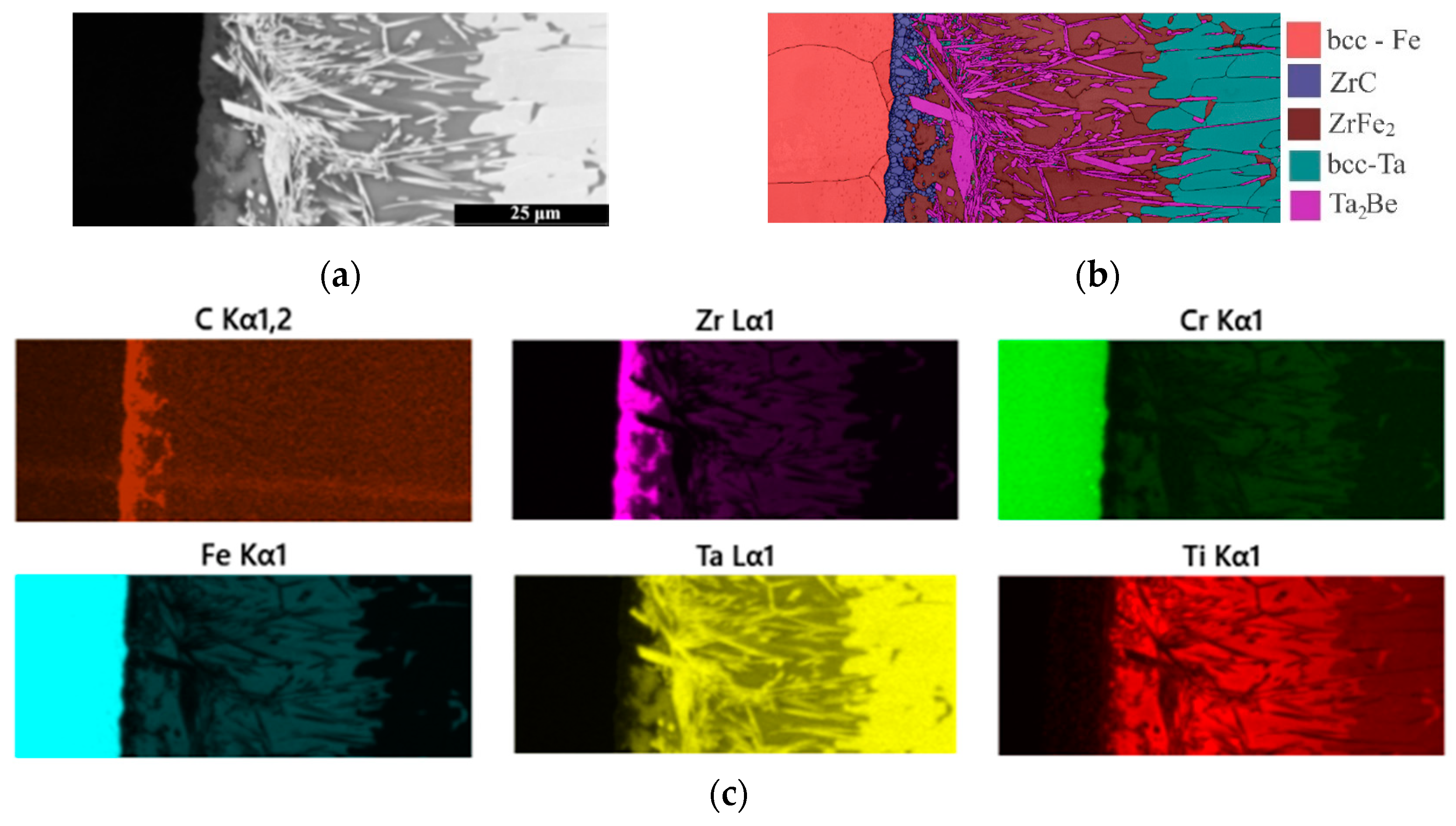
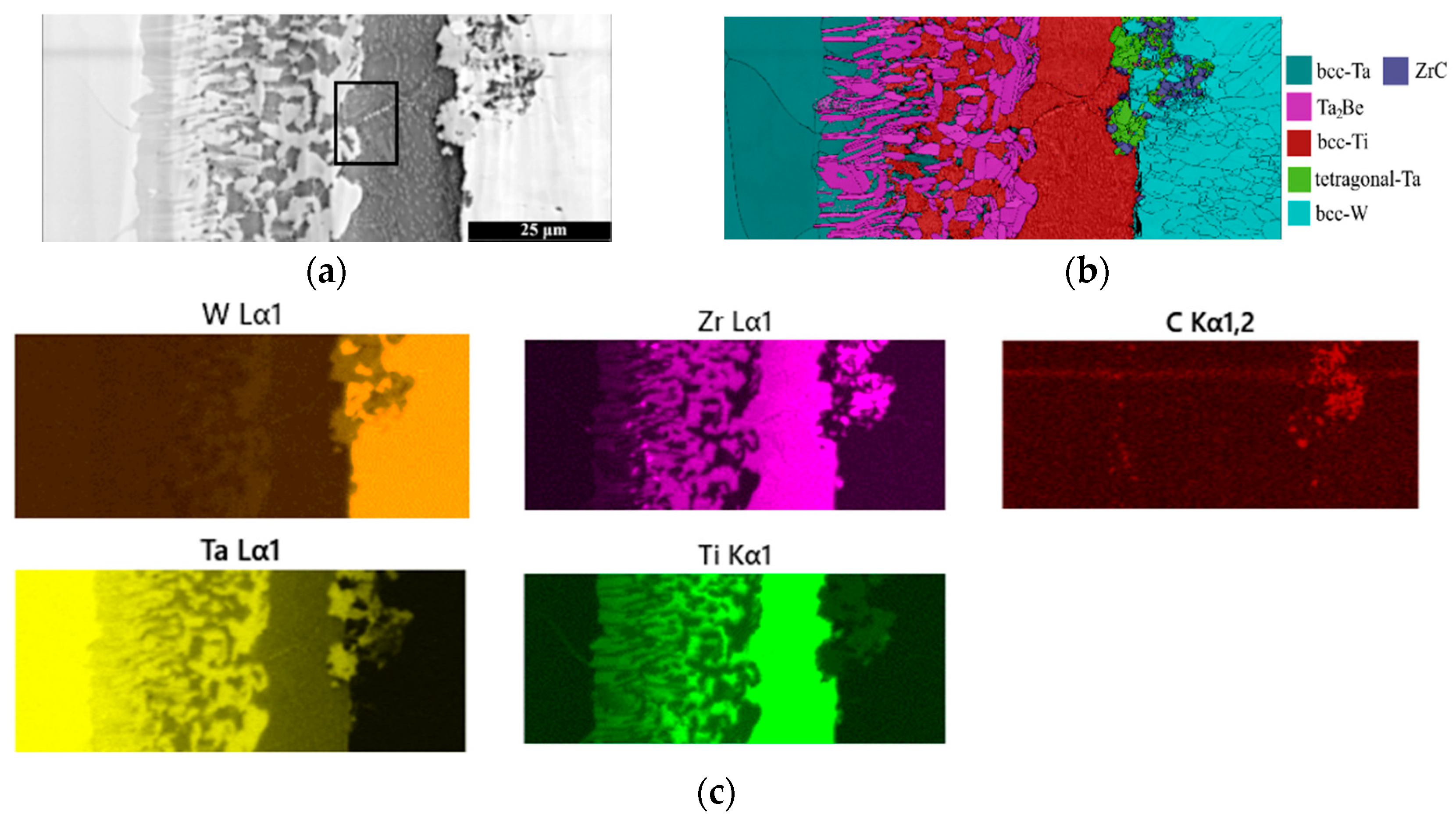
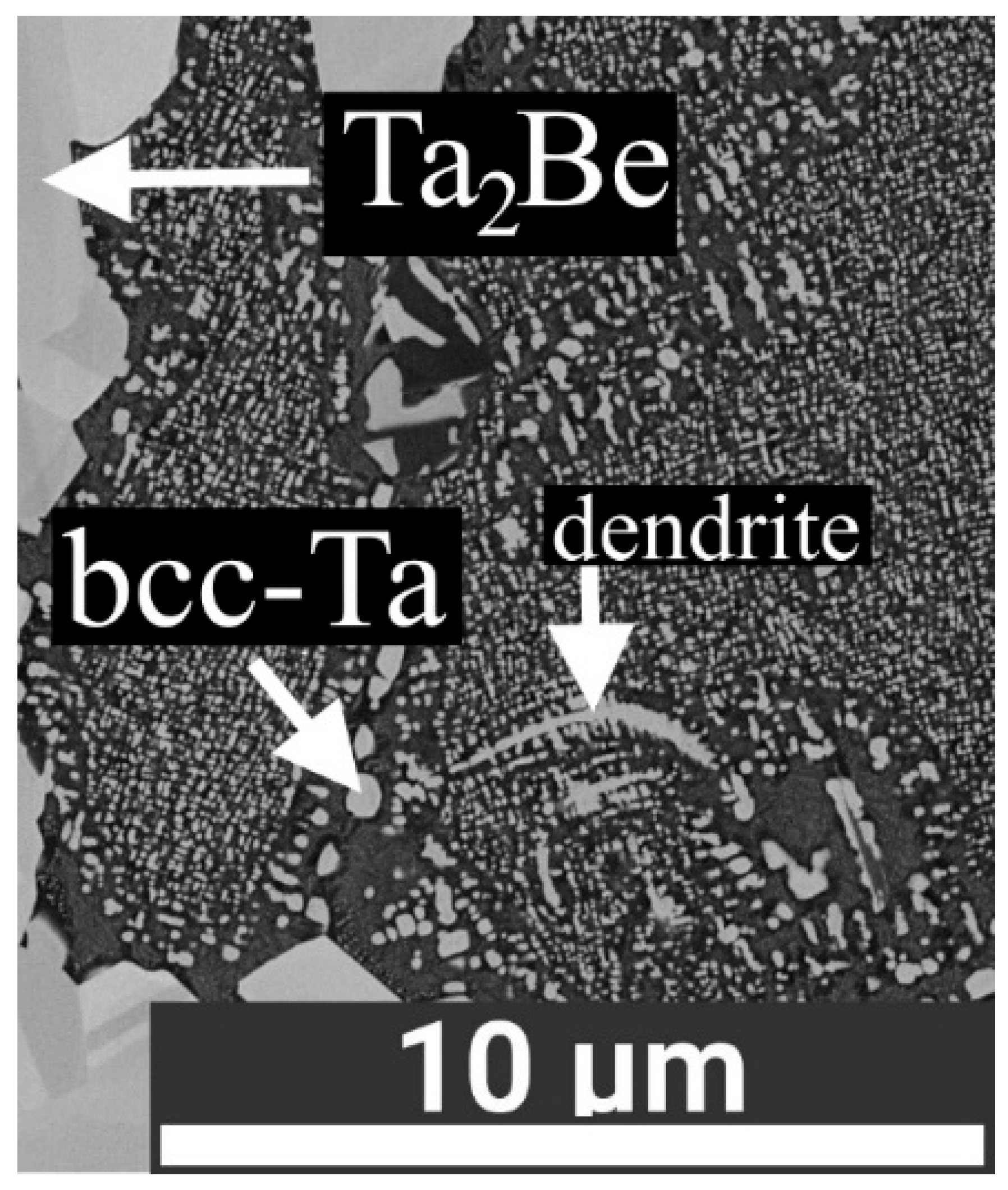
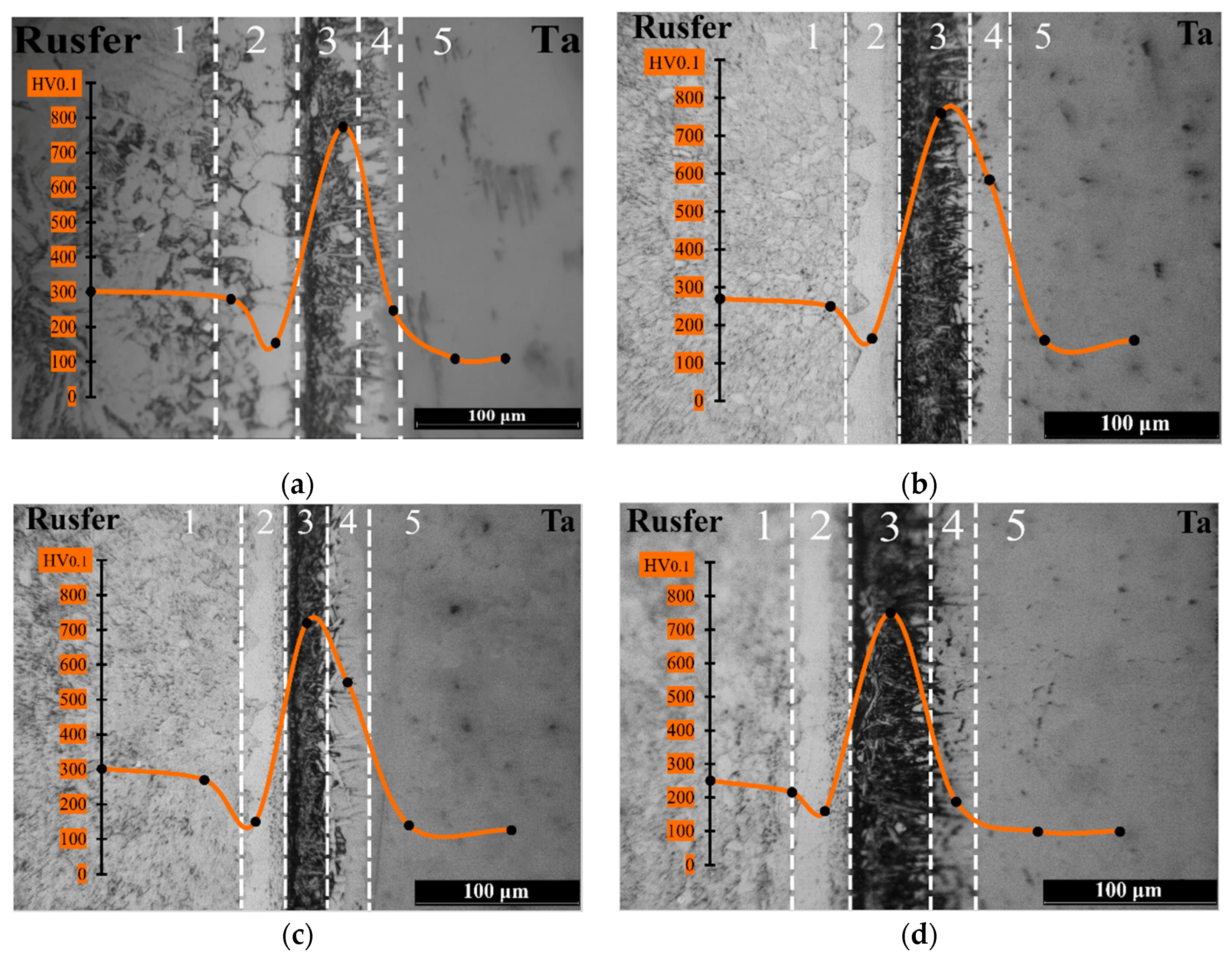
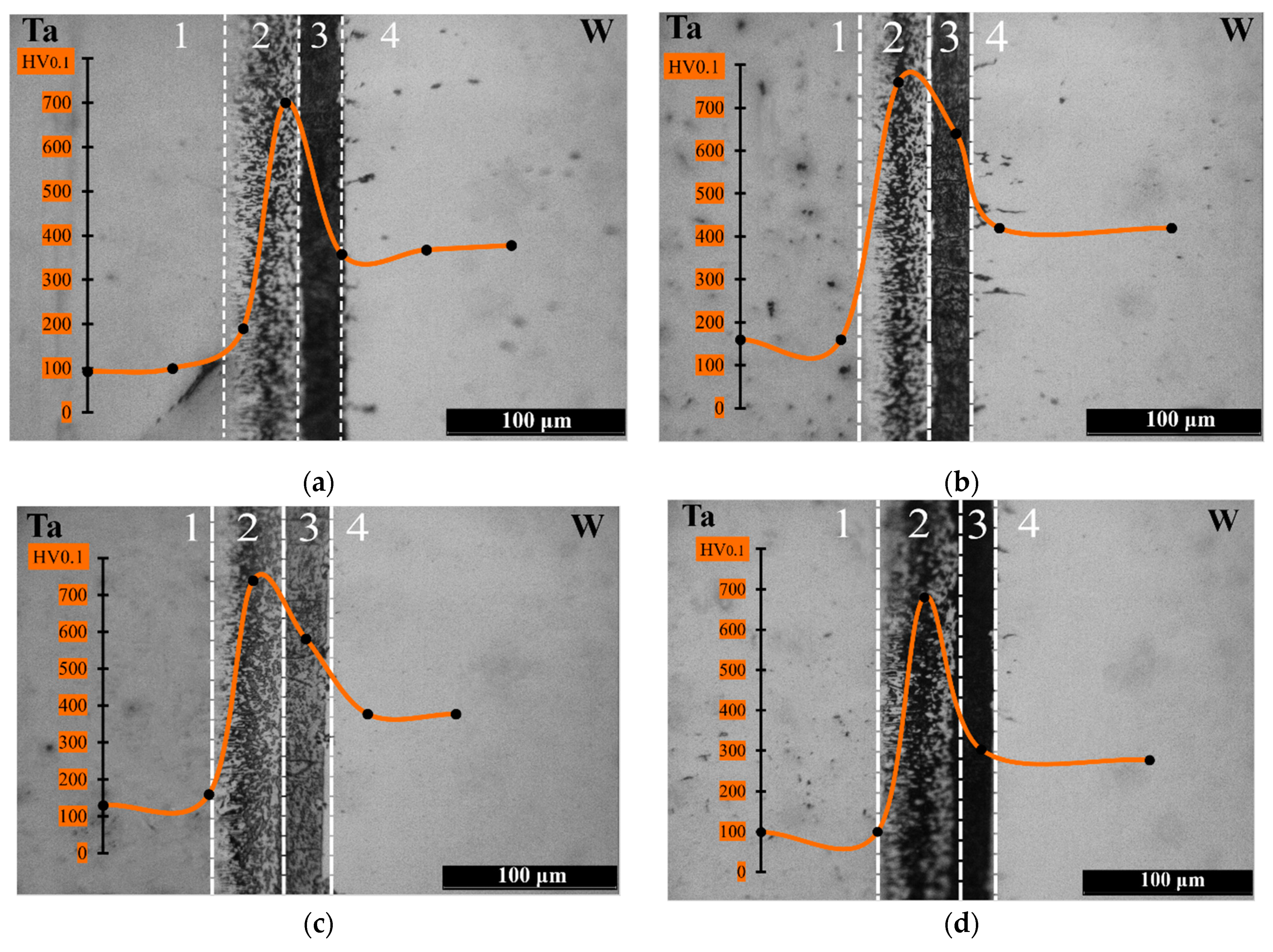
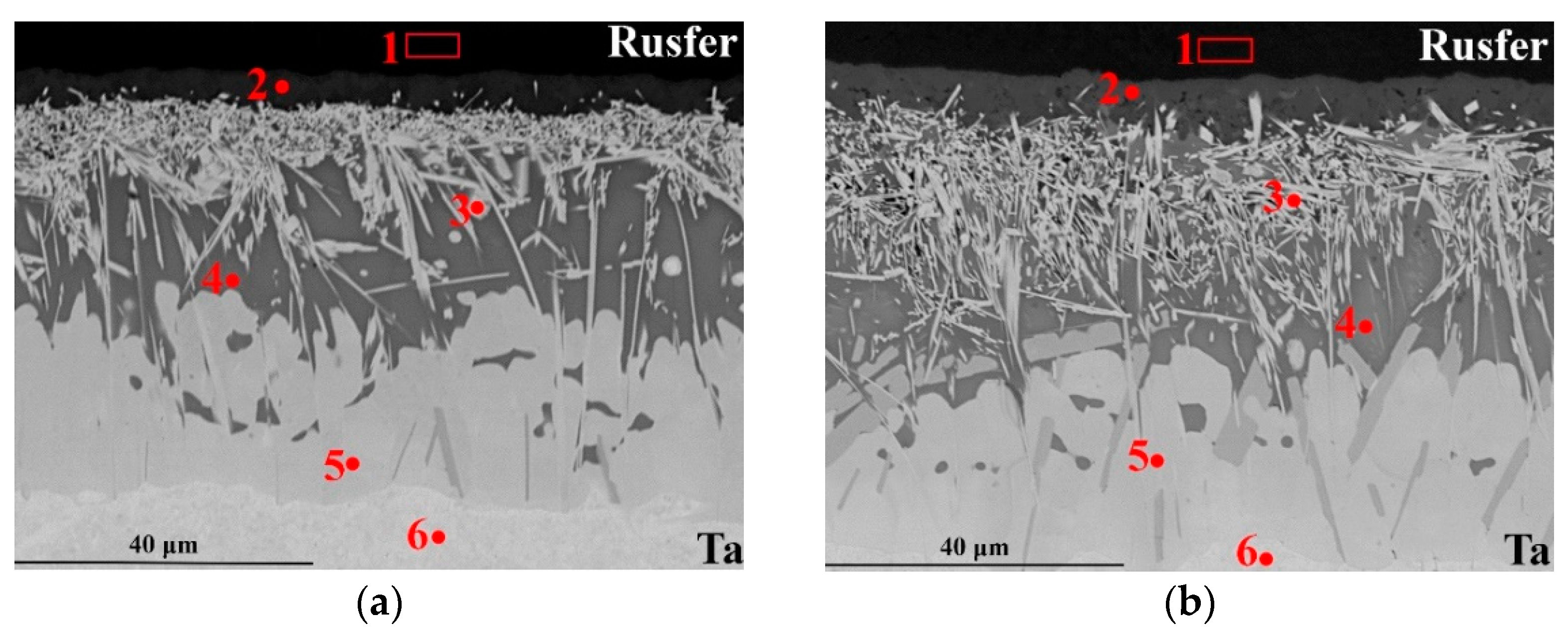
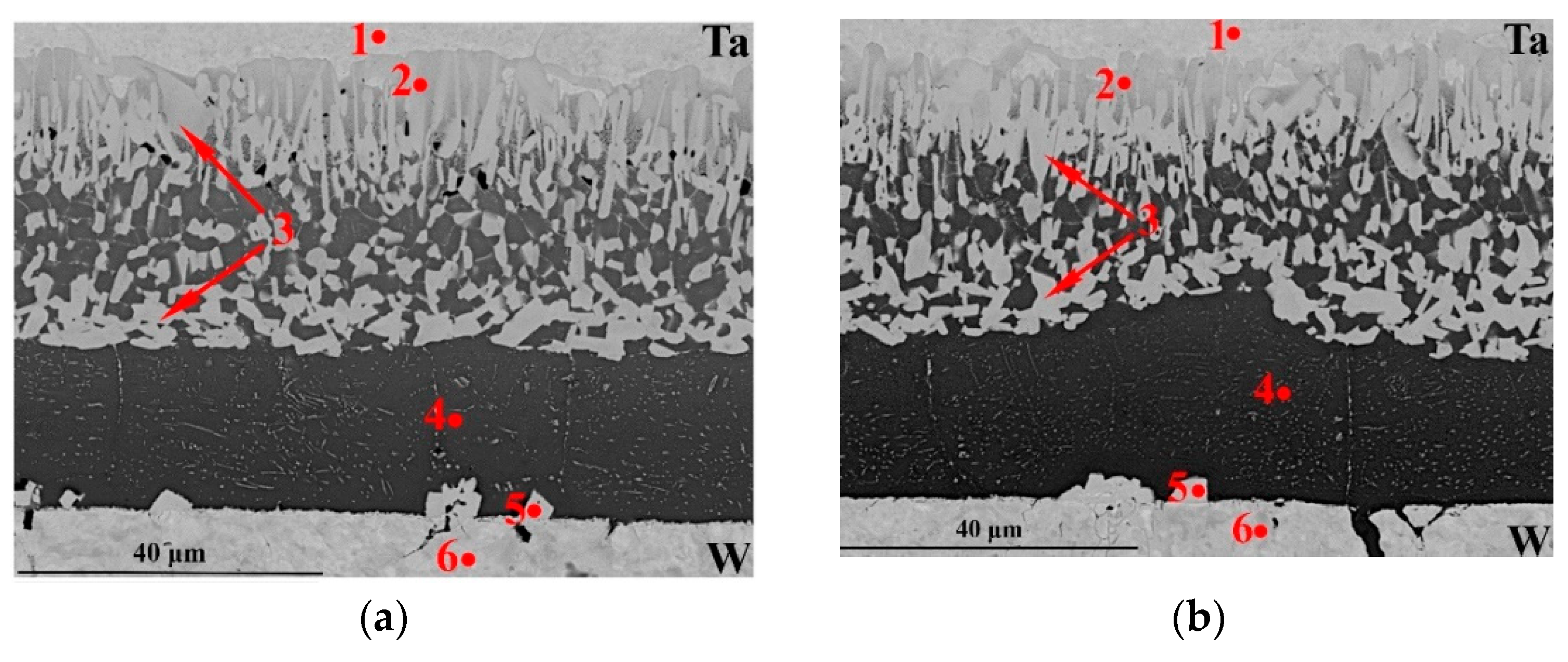
3.1. Microstructural Analysis

Figure 6 shows the micrograph of the whole as-joined sample. We obtained the image in the area close to the fillet region of the sample. No cracks or pores were observed. Rusfer/Ta seam can be divided into the following zones: (1) martensite grains, (2) ferritic grains, (3) interaction zone with sharp phases, (4) interaction zone with elongated grains, (5) pure tantalum. Formation of the ferritic zone was also observed in [15,27,45]. The thickness of the layer increases closer to the fillet, because in Figure 6, a 50 µm ferritic layer formed, but in the central zone of a sample [27], this was 20 µm. In this work (Section 3.2), we present optical images of the central area of the joint, and the thickness is also close to 20–30 µm in different samples. This means that the ferritic layer is thinner while brazing with TiZr4Be compared with Cu-based brazing alloys, where the scientists observed 200 µm [11] and ≈300 µm [46]. We divided the Ta/W seam into the following zones: (1) pure tantalum, (2) mechanical mixture, (3) thick dark layer, (4) pure tungsten. A thin grain boundary depletion of pure W is observed close to the Ta/TiZr4Be/W brazed seam, marked with an arrow in Figure 6.
We used EBSD and EDS analyzes to investigate the seams more precisely. Rusfer/TiZr4Be/Ta seams’ analysis is presented in Figure 7: a—backscattered electron image, b—EBSD phase map, c—EDS maps. Because EDS analysis fails to reliably determine the concentration of light elements (Be, B, H), we do not present Be distribution. By EBSD analysis we determined that the Rusfer/TiZr4Be/Ta seam consists of bcc-Fe, ZrC, Ta2Be, ZrFe2 and bcc-Ta phases. The same microstructure was observed in [27], but no accurate investigation was made there. A ZrC phase formed in the Fe-bcc/ZrFe2 interface, no further appearance of it was observed, and the thickness of the phase varied between 2–10 µm. Ta2Be in the form of sharp needles formed within ZrFe2. Its amount varies in the seam, which can be related to the different gaps between base materials during brazing. The ZrFe2 phase itself also dissolves Ti, Cr, Ta. We presented further quantitative analysis in this article (Section 3.2). Elongated grains after ZrFe2 are bcc-Ta phases. According to EDS maps, strong interaction among the brazing alloy, steel and tantalum occurred. Iron was fully distributed within the interaction layer as well as titanium and zirconium. In addition, tantalum was distributed within the interaction layer.
Figure 8 shows the Ta/W seams’ analysis: a—backscattered electron image, b—EBSD phase map, c–g—EDS maps. By EBSD analysis we determined that the Ta/TiZr4Be/W seam consists of bcc-Ta, Ta2Be, tetragonal-Ta (β-Ta), a solid solution based on bcc-Ti, and ZrC. Formation of ZrC can be related to the mixing of the melts between Rusfer/Ta and Ta/W seams throughout a fillet region [27] that occurs due to high wettability of the brazing alloy. The same morphology of the Ta2Be phase was observed while brazing Ta to boron-nitride [38]. Ta and W dissolved in the brazing alloy melt, which is required for a firm brazed joint. The bcc-Ti based layer dissolved Zr, Ta, and W, which also confirms good interaction. A magnified image of this zone is presented in Figure 9; the image was taken by ultra-high resolution SEM regime. Approximate position of the image is shown in Figure 8a.
Fine bright grains and few dendrites formed on the background of bcc-Ti. By EBSD analysis the grains were seen to be bcc-Ta. We obtained the clear image of the Kukuchi lines only while scanning a phase larger than 0.5 µm. This fine microstructure was likely to be formed during cooling the joint from 1100 °C because of Ti-Ta decay according to the phase diagram [47]. We did not observe such fine grained microstructure while brazing the W-Cr-Y alloy [27].

3.2. Mechanical Characterization

This section presents the results of mechanical tests that included shear tests, thermocycling tests and microhardness measurements.

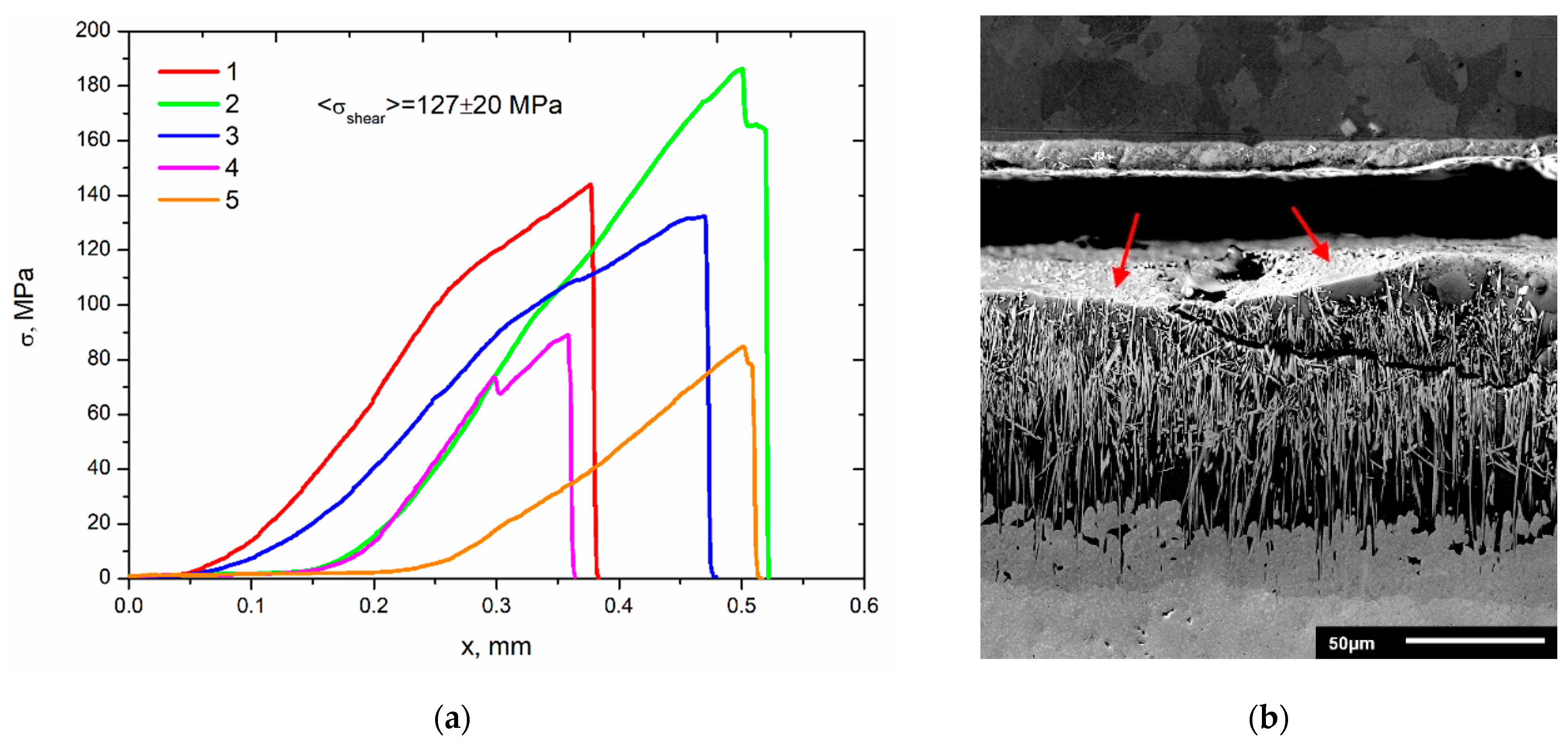
3.2.1. Shear Strength Tests

We measured the shear strength only for as-joined samples. Figure 10a shows the stress-displacement curves of the tested samples. All samples failed along the Rusfer/TiZr4Be/Ta seam. Average shear strength is 127 ± 20 MPa. The lowest shear strength is 80 MPa, whereas the highest is 190 MPa. The test scheme should be improved, because the relative error of 15% is believed to be high. We calculated earlier that a minimum required shear strength for W/steel joint in Water Cooled Lithium Lead blanket is 180 MPa [21], though some attempts can be made to improve the strength of the joint. Figure 10b shows the SEM image in secondary electrons of Rusfer/TiZr4Be/Ta seam after the shear test. The failure occurred throughout the Ta2Be phase. Existence of Ta2Be phase profiles on the failure surface (pointed with arrows in Figure 10b) and a crack propagated through Ta2Be support this assumption. Hence, the dense of this phase should be reduced to improve the shear strength. This can be made by reduction of the brazing alloy melt while using thinner foil. The Ta/TiZr4Be/W seam remained unbroken after the test; hence, it is not necessary to prevent interaction of the melts from Rusfer and W to prevent ZrC phase formation.

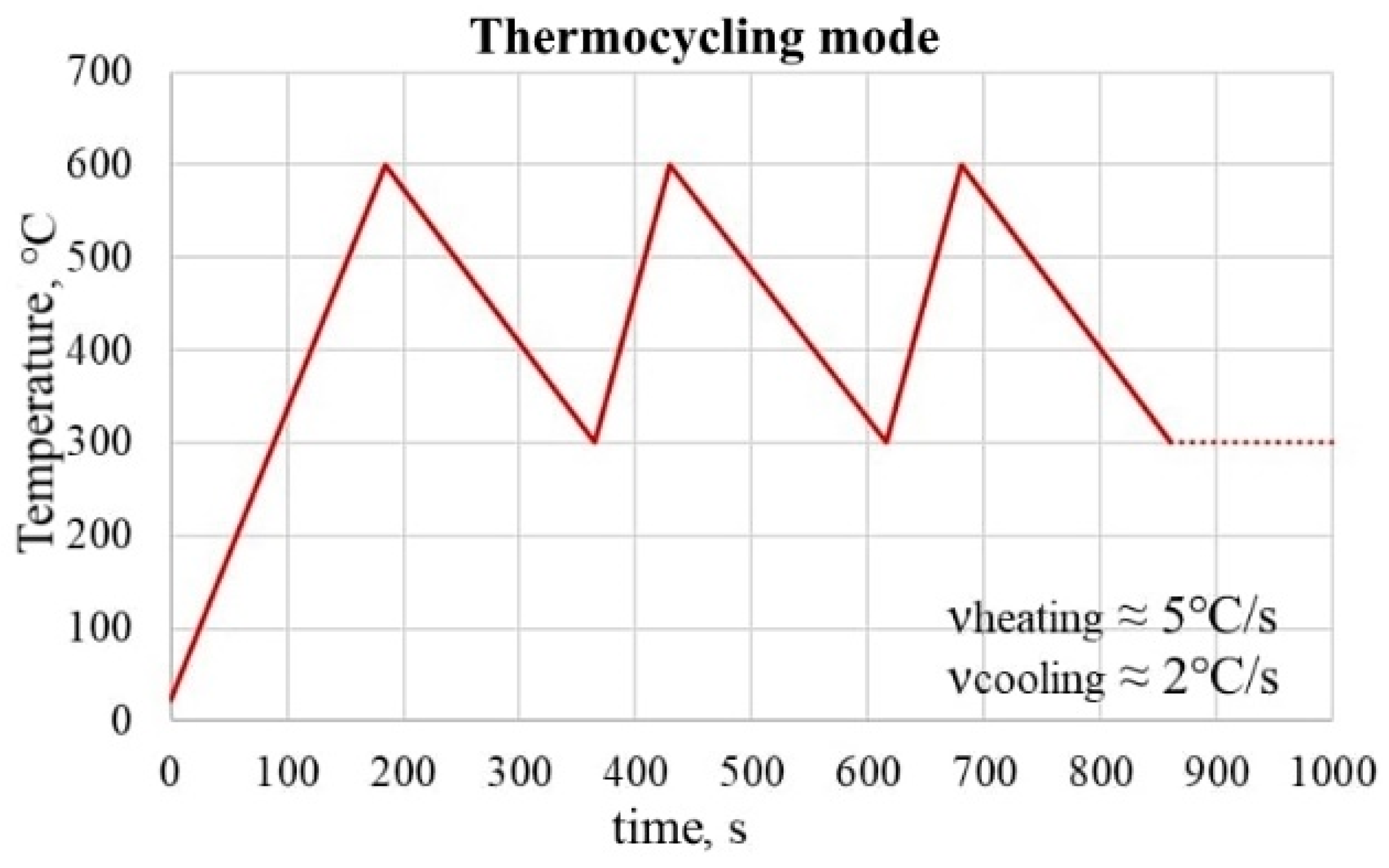
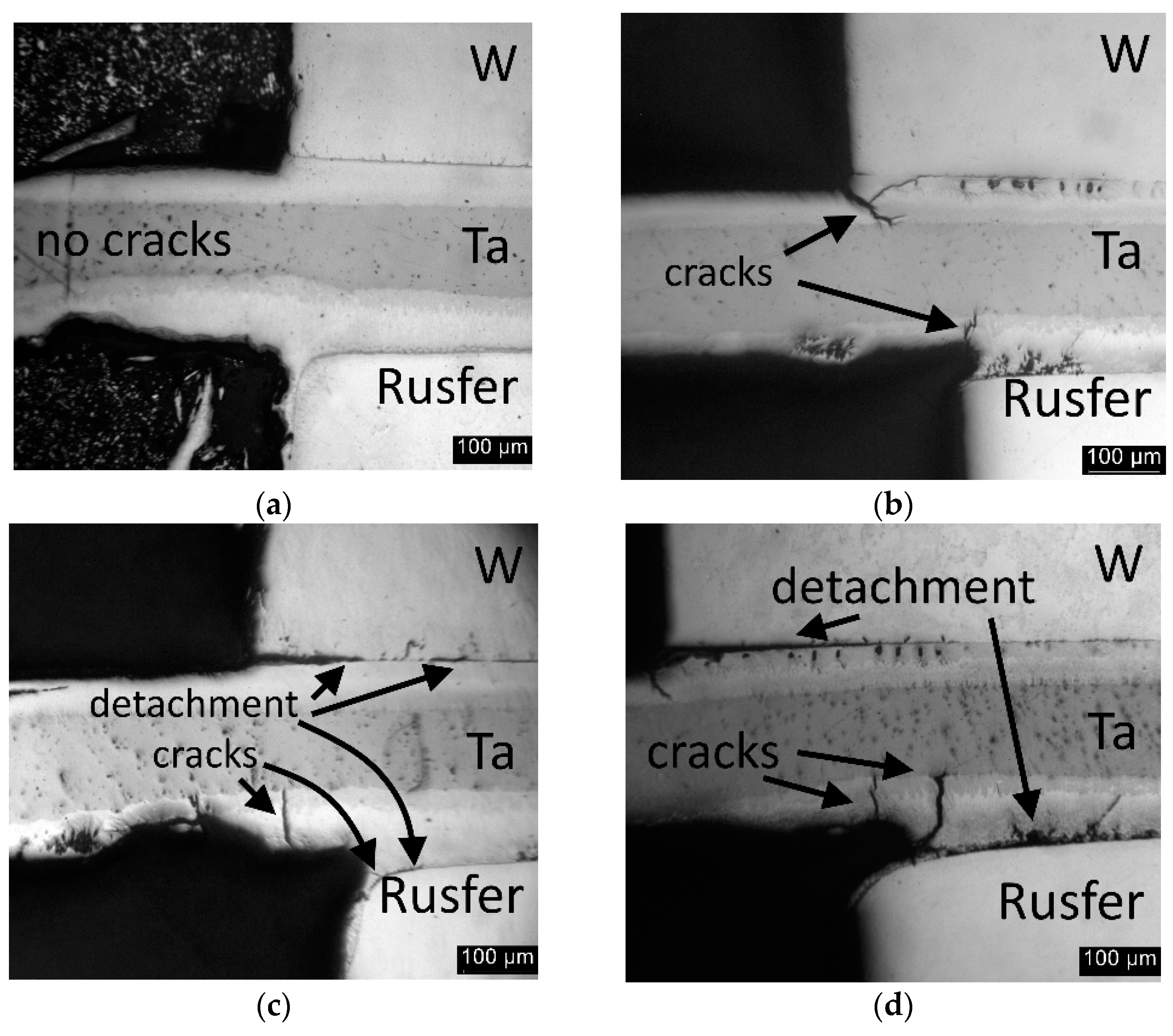
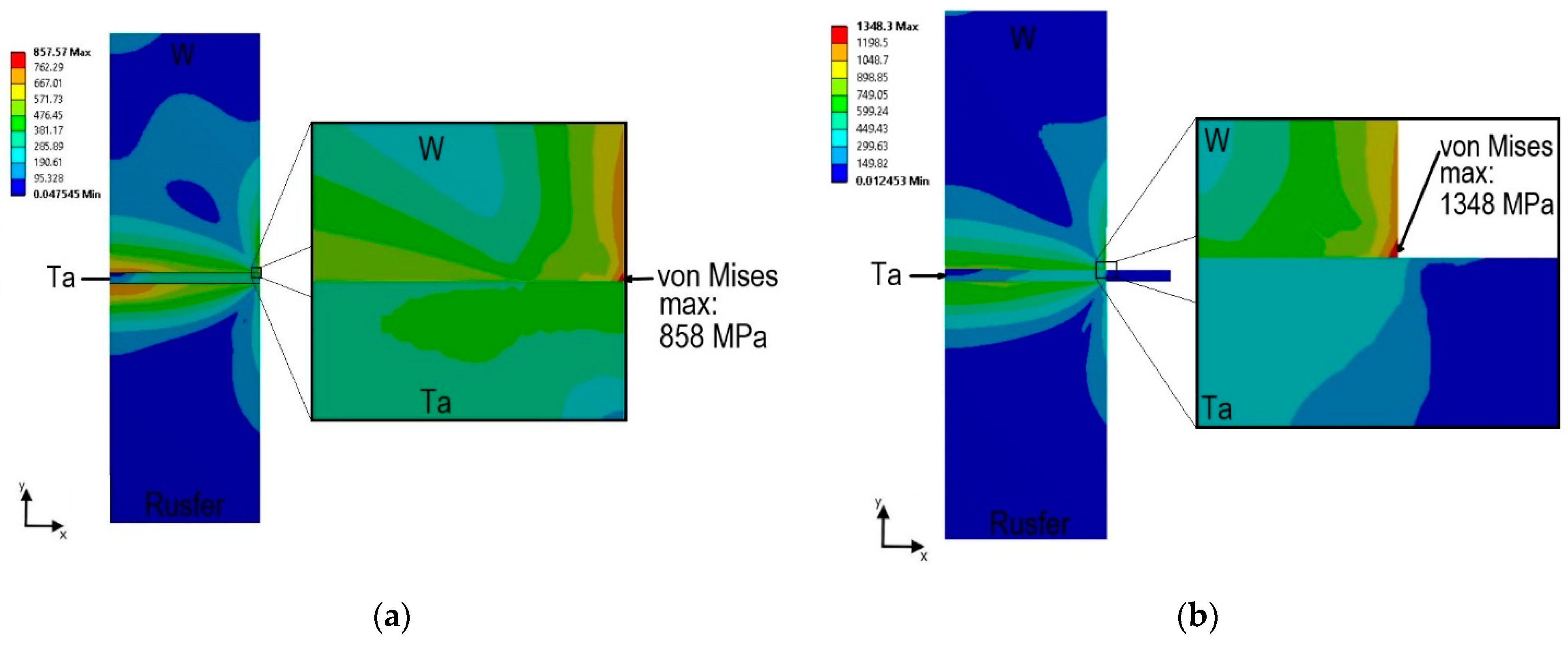
3.2.2. Thermocycling

We subjected four different samples to different numbers of thermocycles: as-joined, 50, 100, and 200. Degradation of the joint accumulated in the fillet region and mostly between tungsten and tantalum which is shown in Figure 11. Some cracks and detachments are observed.
The geometry of a sample is likely to influence the resistance against thermocycling. We calculated that the stress in the fillet region could be reduced by using a tantalum interlayer the same width as the tungsten and steel. Figure 12 shows the results of the FEA calculations. Maximum equivalent von Mises stress is located in the tungsten layer near the edge of the W/Ta contact region in both cases. Its value is 858 MPa when all three layers have the same width and 1348 MPa when the tantalum layer is wider. This means that the geometry with tantalum of the same width as tungsten and steel reduces the stress by 40%.
Magnified and etched images with microhardness profiles are presented further. Figure 13 shows Rusfer/TiZr4Be/Ta seam. Microhardness in the layer 1 is ≈300 HV0.1 which corresponds to thermo-treated Rusfer [48], even when thermocycling microhardness does not decrease, though the temperature higher than 550 °C negatively affects the RAFM steel’s microstructure. After the thermocycling, loss of martensite structure in layer 1 occurred. The scope of this work was aimed at brazing rather than at the steels’ microstructure, so we did not pay close attention to the steel.
Microhardness of ferritic grains in zone 2 is close to 170 HV0.1 in all cases from as-joined to 200 thermo-cycled sample. No further growth of ferritic grains occurred. Ferritization and further carbide formation can be expected if the operation temperature exceeds 700 °C, because the ferritic layer forms during diffusion bonding at a temperature higher than 700 °C [45].
Interaction layer 3 is quite hard: microhardness almost reaches 800 HV0.1 and does not decrease after thermocycling. Microhardness of the layer 4 lies between the third and fifth layer. Pure tantalum characterized with 100 HV0.1 and did not harden after 200 thermocycles, hence no further dissolution of other components was observed.
Figure 14 shows the microstructure of the Ta/TiZr4Be/W brazed joint with the microhardness profiles. The thickness of the seam did not vary from sample to sample as was seen in the Rusfer/TiZr4Be/Ta joint. The microhardness of tantalum in layer 1 is obviously the same as in the Rusfer/TiZr4Be/Ta seam. The mechanical mixture of Ti-based solid solution with Ta2Be phase is close to 700 HV0.1, which should be related to the beryllide phase, because the third layer is softer and more characterized by 300–600 HV0.1. This spread of values can be related to the complex microstructure of this layer, as presented in Figure 6. The microhardness of pure tungsten is ≈420 HV0.1. The microhardness in this joint is higher than for the joints with vanadium interlayer and amorphous Cu-based brazing alloy, where the microhardness in the interaction zone lies in the range between 100–400 HV0.1 [40]. Thermocycling did not lead to any change in the microhardness qualitative and quantitative profile.
Comparing with Rusfer/V/W joints obtained using Cu-Ti [11] and Cu-Ge [40] rapidly solidified into foil brazing alloys, microhardness values in the Rusfer/TiZrBe/Ta/TiZrBe/W joint were higher.
We carried out EDS analysis of the phases forming the seams to check if the thermocycling affects the phase composition. SEM images of the as-joined and 200 thermo-cycled seams are presented in Figure 15 (Rusfer/Ta) and Figure 16 (Ta/W). Table 1 presents the quantitative analysis of the points.
Figure 15a shows the as-joined Rusfer/Ta seam (Figure 15b) after 200 thermocycles. The compositions of 2–6 points are an average number collected from at least three measurements, and the composition of the 1 point is a measurement by a square zone, outlined in Figure 15. Composition of the steel (point 1) did not change after thermocycling, hence no further diffusion from the seam observed. The ZrC phase (point 2) differs mostly with Si, which could have been dissolved from the steel. Compared with the as-joined composition of the Ta2Be phase (point 3), Zr and Cr start to dissolute more in the needles. The ZrFe2 (point 4) phase also dissolves Ti, Ta and Cr. It is hard to conclude whether the compositions differ because of thermocycling, or because of local heterogeneity. The same occurs for the fifth and the sixth points, because on EDS maps (Figure 7) the contrast of the components varies.
Figure 16a shows the as-joined Ta/TiZr4B/W seam, and Figure 16b after 200 thermocycles. The compositions of 1–6 points are an average number collected from at least three measurements. Point 1 is pure Ta for both samples. In this seam we can confidently claim that no further erosion of Ta was observed during 200 thermocycles, because the thickness and morphology of layer 2 are the same. Tantalum in point 2 dissolved a different amount of Ti, which corresponds with the Ta-Ti [47] phase diagram, but did not dissolve Zr. Ta and Ti have mutual solubility, whereas Ta-Zr only form a mechanical mixture at low temperatures [49]. The Ta2Be phase (point 3) remained the same in its morphology and composition after 200 thermocycles, as well as the Ti-based solid solution (point 4). The β-Ta (point 5) has a slightly different composition in the as-joined and 200 thermo-cycled samples, but still based on the tantalum solid solution. Pure tungsten (point 6) remained pure after thermocycling.
Therefore, the morphology and composition of the brazed joint did not change after 200 thermocycles in a range between 300–600 °C.

4. Conclusions

Brazing of the Rusfer/TiZr4Be/Ta/TiZr4Be/W joint was successfully carried out under 1100 °C 1 h + 720 °C 3 h brazing mode. Fully reduced activation 48Ti-48Zr-4Be wt.% (TiZr4Be) rapidly solidified into foil when a brazing alloy 70 μm thick was used. By EDS and EBSD analysis, microstructure of the joint was determined. The Rusfer/TiZr4Be/Ta seam consists of bcc-Fe, ZrC, Ta2Be, ZrFe2 and bcc-Ta phases. The Ta/TiZr4Be/W seam consists of bcc-Ta, Ta2Be, β-Ta, and solid solution based on bcc-Ti, ZrC.
Shear strength of the as-joined composition is 127 ± 20 MPa. Failure occurs along Rusfer/Ta seam throughout the Ta2Be phase.
Thermocycling tests were carried out in a vacuum in the temperature range between 300–600 °C (Vheating = 5 °C/min, Vcooling = 2 °C/min). After thermocycling, neither morphology nor composition of the phases in the seams changed, no did microhardness. Degradation of samples occurred in the fillet region, but the samples remained integrated after 200 thermocycles. Stresses in the fillet region can be reduced by using tantalum of the same width as the tungsten and steel.
TiZr4Be brazing alloy seems to be prospective in the DEMO application; however, further improvement of the Rusfer/TiZr4Be/Ta seam is needed. This can be processed with a reduction of the Ta2Be phase.

Author Contributions

Conceptualization, A.S., methodology, D.B. and A.S.; software, V.V.; validation, D.B., J.G. and V.K.; formal analysis, D.B. and J.G.; investigation, D.B., J.G. and V.K.; resources, P.S. and M.S.; data curation, V.V.; writing—original draft preparation, D.B.; writing—review and editing, A.S.; visualization, V.K.; supervision, O.S.; project administration, O.S.; funding acquisition, A.S. All authors have read and agreed to the published version of the manuscript.

Funding

The work presented in Section 3.1 was supported by the Russian Science Foundation project No. 17-72-20191. The work presented in Section 3.2 was supported by RFBR, project number 20-32-90174.

Institutional Review Board Statement

Not applicable.

Informed Consent Statement

Not applicable.

Data Availability Statement

Data is contained within the article.

Acknowledgments

The authors acknowledge Tescan Russia for technological support and Bochvar High-Technology Research Institute of Inorganic Materials for the supply of Rusfer.

Conflicts of Interest

The authors declare no conflict of interest.

References

  1. Barrett, T.R.; Ellwood, G.; Pérez, G.; Kovari, M.; Fursdon, M.; Domptail, F.; Kirk, S.; Mcintosh, S.C.; Roberts, S.; Zheng, S.; et al. Progress in the Engineering Design and Assessment of the European DEMO First Wall and Divertor Plasma Facing Components. Fusion Eng. Des. 2016, 109111, 917–924. [Google Scholar] [CrossRef] [Green Version]
  2. Subbotin, M.L.; Kurbatov, D.K.; Filimonova, E.A. Review of the state of research of demonstration thermonuclear reactors in the world. VANT Fusion 2010, 3, 55–74. (In Russian) [Google Scholar]
  3. Tobita, K.; Hiwatari, R.; Utoh, H.; Miyoshi, Y.; Asakura, N.; Sakamoto, Y.; Someya, Y.; Homma, Y.; Nakamura, M.; Hoshino, K.; et al. Overview of the DEMO Conceptual Design Activity in Japan. Fusion Eng. Des. 2018, 136, 1024–1031. [Google Scholar] [CrossRef]
  4. Federici, G.; Bachmann, C.; Barucca, L.; Biel, W.; Boccaccini, L.; Brown, R.; Bustreo, C.; Ciattaglia, S.; Cismondi, F.; Coleman, M.; et al. DEMO Design Activity in Europe: Progress and Updates. Fusion Eng. Des. 2018, 136, 729–741. [Google Scholar] [CrossRef]
  5. Ioltukhovsky, A.G.; Kondrat’ev, V.P.; Leont’eva-Smirnova, M.V.; Votinov, S.N.; Shamardin, V.K.; Povstyanko, A.V.; Bulanova, T.M. Metallurgical Aspects of Possibility of 9–12% Chromium Steel Application as a Structural Material for First Wall and Blanket of Fusion Reactors. J. Nucl. Mater. 1996, 233–237, 299–304. [Google Scholar] [CrossRef]
  6. Tavassoli, A.A.F.; Alamo, A.; Bedel, L.; Forest, L.; Gentzbittel, J.M.; Rensman, J.W.; Diegele, E.; Lindau, R.; Schirra, M.; Schmitt, R.; et al. Materials Design Data for Reduced Activation Martensitic Steel Type EUROFER. J. Nucl. Mater. 2004, 329–333, 257–262. [Google Scholar] [CrossRef]
  7. Basuki, W.W.; Aktaa, J. Investigation on the Diffusion Bonding of Tungsten and EUROFER97. J. Nucl. Mater. 2011, 417, 524–527. [Google Scholar] [CrossRef]
  8. Bachurina, D.; Suchkov, A.; Kalin, B.; Sevriukov, O.; Fedotov, I.; Dzhumaev, P.; Ivannikov, A.; Leont’eva-Smirnova, M.; Mozhanov, E. Joining of Tungsten with Low-Activation Ferritic–Martensitic Steel and Vanadium Alloys for Demo Reactor. Nucl. Mater. Energy 2018, 15, 135–142. [Google Scholar] [CrossRef]
  9. Joints, M. Di Ff Usion Bonding and Transient Liquid Phase (TLP) Bonding of Type 304 and 316 Austenitic Stainless Steel—A Review of Similar and Dissimilar Material Joints. Metals 2020, 10, 613. [Google Scholar]
  10. Basuki, W.W.; Aktaa, J. Investigation of Tungsten/EUROFER97 Diffusion Bonding Using Nb Interlayer. Fusion Eng. Des. 2011, 86, 2585–2588. [Google Scholar] [CrossRef]
  11. Bachurina, D.; Suchkov, A.; Gurova, J.; Savelyev, M.; Dzhumaev, P.; Kozlov, I.; Svetogorov, R.; Leont’eva-Smirnova, M.; Sevryukov, O. Joining Tungsten with Steel for DEMO: Simultaneous Brazing by Cu-Ti Amorphous Foils and Heat Treatment. Fusion Eng. Des. 2020, 162, 112099. [Google Scholar] [CrossRef]
  12. Chen, H.Y.; Luo, L.M.; Zhang, J.; Zan, X.; Zhu, X.Y.; Luo, G.N.; Wu, Y.C. Investigation on W/Fe Diffusion Bonding Using Ti Foil and Ti Powder Interlayer by SPS. J. Nucl. Mater. 2015, 467, 566–571. [Google Scholar] [CrossRef]
  13. Liu, W.; Pang, X.; Cai, Q.; Ma, Y.; Zhu, W. Fabrication of W/Steel Joint Using Hot Isostatic Pressing with Ti/Cu/Ti Liquid Forming Interlayer. Fusion Eng. Des. 2018, 135, 59–64. [Google Scholar] [CrossRef]
  14. Kalin, B.A.; Fedotov, V.T.; Sevrjukov, O.N.; Kalashnikov, A.N.; Suchkov, A.N.; Moeslang, A.; Rohde, M. Development of Brazing Foils to Join Monocrystalline Tungsten Alloys with ODS-EUROFER Steel. J. Nucl. Mater. 2007, 367–370B, 1218–1222. [Google Scholar] [CrossRef]
  15. De Prado, J.; Sánchez, M.; Stan, G.; Galatanu, A.; Ureña, A. Effect of Cr and V Coatings on W Base Material in W-Eurofer Brazed Joints for Fusion Applications. Fusion Eng. Des. 2020, 159, 111748. [Google Scholar] [CrossRef]
  16. Zhu, W.; Qiang, J.; Wang, Y.; Sun, J.; Wang, J.; Lian, Y.; Feng, F.; Liu, X. A Ti-Fe-Sn Thin Film Assembly for Joining Tungsten and Reduced Activation Ferritic-Martensitic Steels. Mater. Des. 2017, 125, 55–61. [Google Scholar] [CrossRef]
  17. Liu, W.; Wang, Z.; Ma, Y.; Cai, Q. Investigation of Tungsten/Steel Brazing Using Ta and Cu Interlayer. Fusion Eng. Des. 2016, 113, 102–108. [Google Scholar] [CrossRef]
  18. Tan, C.; Wang, C.; Wang, S.; Wang, G.; Ji, L.; Tong, Y.; Duan, X.M. Investigation on 316L/316L-50W/W Plate Functionally Graded Materials Fabricated by Spark Plasma Sintering. Fusion Eng. Des. 2017, 125, 171–177. [Google Scholar] [CrossRef]
  19. Cai, Q.; Liu, W.; Ma, Y.; Liu, H. Microstructure, Residual Stresses and Mechanical Properties of Diffusion Bonded Tungsten-Steel Joint Using a V/Cu Composite Barrier Interlayer. Int. J. Refract. Met. Hard Mater. 2015, 48, 312–317. [Google Scholar] [CrossRef]
  20. Litunovsky, N.; Alekseenko, E.; Makhankov, A.; Mazul, I. Development of the Armoring Technique for ITER Divertor Dome. Fusion Eng. Des. 2011, 86, 1749–1752. [Google Scholar] [CrossRef]
  21. Bachurina, D.; Vorkel, V.; Suchkov, A.; Gurova, J.; Ivannikov, A.; Penyaz, M.; Fedotov, I.; Sevryukov, O.; Kalin, B. Overview of the Mechanical Properties of Tungsten/Steel Brazed Joints for the Demo Fusion Reactor. Metals 2021, 11, 209. [Google Scholar] [CrossRef]
  22. Ma, Y.Z.; Cai, Q.S.; Liu, W.S.; Liu, S.H. Microstructure and Mechanical Properties of Brazed Tungsten/Steel Joint for Divertor Applications. Mater. Sci. Forum 2014, 789, 384–390. [Google Scholar] [CrossRef]
  23. Cai, Q.; Liu, W.; Ma, Y.; Wang, Z. Diffusion Brazing of Tungsten and Steel Using Ti-Ni Liquid Phase Forming Interlayer. Fusion Eng. Des. 2015, 91, 67–72. [Google Scholar] [CrossRef]
  24. de Prado, J.; Sánchez, M.; Ureña, A. Evaluation of Mechanically Alloyed Cu-Based Powders as Filler Alloy for Brazing Tungsten to a Reduced Activation Ferritic-Martensitic Steel. J. Nucl. Mater. 2017, 490, 188–196. [Google Scholar] [CrossRef]
  25. Bachurina, D.; Suchkov, A.; Gurova, Y.; Sevryukov, O. Investigation of a Brazed Joint EK-181 / V / W Obtained by Cu-Sn and Cu-Ti Amorphous Foils. IOP Conf. Ser. Mater. Sci. Eng. 2020, 1005, 7. [Google Scholar] [CrossRef]
  26. Zhang, Y.; Galloway, A.; Wood, J.; Robbie, M.B.O.; Easton, D.; Zhu, W. Interfacial Metallurgy Study of Brazed Joints between Tungsten and Fusion Related Materials for Divertor Design. J. Nucl. Mater. 2014, 454, 207–216. [Google Scholar] [CrossRef] [Green Version]
  27. Bachurina, D.; Tan, X.-Y.; Klein, F.; Suchkov, A.; Litnovsky, A.; Schmitz, J.; Gonzalez-Julian, J.; Bram, M.; Coenen, J.W.; Wu, Y.-C.; et al. Self-Passivating Smart Tungsten Alloys for DEMO: A Progress in Joining and Upscale for a First Wall Mockup. Tungsten 2021, 3, 101–115. [Google Scholar] [CrossRef]
  28. Heuer, S.; Coenen, J.W.; Pintsuk, G.; Matějíček, J.; Vilémová, M.; Linsmeier, C. Overview of Challenges and Developments in Joining Tungsten and Steel for Future Fusion Reactors. Phys. Scr. 2020, T171, 014028. [Google Scholar] [CrossRef]
  29. Van der Schaaf, B.; Tavassoli, F.; Fazio, C.; Rigal, E.; Diegele, E.; Lindau, R.; LeMarois, G. The Development of EUROFER Reduced Activation Steel. Fusion Eng. Des. 2003, 69, 197–203. [Google Scholar] [CrossRef]
  30. Chernov, V.M.; Leont, M.V.; Mozhanov, E.M.; Nikolaeva, N.S.; Tyumentsev, A.N.; Polekhina, N.A.; Yu Litovchenko, I.; Astafurova, E.G. Thermal Stability of the Microstructure of 12% Chromium Ferritic–Martensitic Steels after Long-Term Aging at High Temperatures. Tech. Phys. 2016, 61, 209–214. [Google Scholar] [CrossRef]
  31. Chernov, V.M.; Leont’eva-Smirnova, M.V.; Potapenko, M.M.; Polekhina, N.A.; Litovchenko, I.Y.; Tyumentsev, A.N.; Astafurova, E.G.; Khromova, L.P. Structure–Phase Transformations and Physical Properties of Ferritic–Martensitic 12% Chromium Steels EK-181 and ChS-139. Tech. Phys. 2016, 61, 97–102. [Google Scholar] [CrossRef]
  32. Ivannikov, A.A.; Sevryukov, O.N.; Vertkov, A.V.; Penyaz, M.A.; Misnikov, V.E.; Kochnov, Y.O.; Morokhov, P.V.; Lyublinskiy, I.E. High-Temperature Brazing of Molybdenum to 12Cr18Ni10Ti Steel with the CTEMET 1301 Rapidly Quenched Nickel Brazing Alloy. Weld. Int. 2017, 31, 767–772. [Google Scholar] [CrossRef]
  33. Kalin, B.A.; Suchkov, A.N.; Fedotov, V.T.; Sevryukov, O.N.; Ivanniko, A.A.; Gervash, A.A. Brazing of Be with CuCrZr-Bronze Using Copper-Based Filler Metal STEMET. Nucl. Mater. Energy 2016, 9, 388–393. [Google Scholar] [CrossRef] [Green Version]
  34. Logvenchev, I.S.; Ivannikov, A.A.; Volkov, A.A.; Arofikin, N.V.; Sevryukov, O.N.; Fedotov, V.T.; Suchkov, A.N.; Fedotov, I.V.; Skrytnyi, V.I. The Brazing of Nickel Alloys for Nuclear Reactor with the Using of the Rapidly-Quenched Filler Metals. Inorg. Mater. Appl. Res. 2014, 5, 263–267. [Google Scholar] [CrossRef]
  35. Fedotov, V.T.; Suchkov, A.N.; Kalin, B.A.; Sevryukov, O.N.; Ivannikov, A.A. Stemet Solders for Brazing of Modern Technology Materials. Tsvetnye Met. 2014, 1, 32–37. [Google Scholar]
  36. Otto, J.L.; Penyaz, M.; Schmiedt-Kalenborn, A.; Knyazeva, M.; Ivannikov, A.; Kalin, B.; Walther, F. Effect of Phase Formation Due to Holding Time of Vacuum Brazed AISI 304L/NiCrSiB Joints on Corrosion Fatigue Properties. J. Mater. Res. Technol. 2020, 9, 10550–10558. [Google Scholar] [CrossRef]
  37. Tanner, L.E.; Ray, R.; Cline, C.F. Amorphous Metal Alloys in the Beryllium-Titanium-Zirconium System. U.S. Patent 4,050,931, 27 September 1977. [Google Scholar]
  38. Fedotov, I.V.; Suchkov, A.N.; Fedotov, V.T.; Sevryukov, O.N.; Kalin, B.A.; Ivannikov, A.A. Brazing of Hexagonal Boron-Nitride Ceramics with VT1-0 Titanium Alloy Using a Rapidly Quenched Titanium-Based Brazing Alloy. Weld. Int. 2015, 29, 222–226. [Google Scholar] [CrossRef]
  39. Leontyeva-Smirnova, M.V.; Agafonov, A.N.; Ermolaev, G.N.; Ioltukhovsky, A.G.; Mozhanov, E.M.; Reviznikov, L.I.; Tsvelev, V.V.; Chernov, V.M.; Bulanova, T.M.; Golovanov, V.N.; et al. Microstructure and Mechanical Properties of Low Activated Ferritic-Martensitic Steel EK-181 (RUSFER-EK-181). Promis. Mater. 2006, 6, 40–52. (In Russian) [Google Scholar]
  40. Bachurina, D.; Suchkov, A.; Filimonov, A.; Fedotov, I.; Savelyev, M.; Sevryukov, O.; Kalin, B. High-Temperature Brazing of Tungsten with Steel by Cu-Based Ribbon Brazing Alloys for DEMO. Fusion Eng. Des. 2019, 146, 1343–1346. [Google Scholar] [CrossRef]
  41. Penyaz, M.A.; Ivannikov, A.A.; Kalin, B.A.; Dzhumaev, P.S. Thermal Fatigue Damage of Steel Joints Brazed with Various Nickel Filler Metals. Non-Ferrous Met. 2019, 46, 33–39. [Google Scholar] [CrossRef]
  42. Fedotov, I.; Suchkov, A.; Sliva, A.; Dzhumaev, P.; Kozlov, I.; Svetogorov, R.; Bachurina, D.; Sevryukov, O.; Corrosion, C. Study of the Microstructure and Thermomechanical Properties of Mo/Graphite Joint Brazed with Ti–Zr–Nb–Be Powder Filler Metal. J. Mater. Sci. 2021, 56, 11557–11568. [Google Scholar] [CrossRef]
  43. Harrington, C. Dynamic Modelling of Balance of Plant Systems for a Pulsed DEMO Power Plant. Fusion Eng. Des. 2015, 98–99, 2147–2151. [Google Scholar] [CrossRef]
  44. Heuer, S.; Weber, T.; Pintsuk, G.; Coenen, J.W.; Matejicek, J.; Linsmeier, C. Aiming at Understanding Thermo-Mechanical Loads in the First Wall of DEMO: Stress–Strain Evolution in a Eurofer-Tungsten Test Component Featuring a Functionally Graded Interlayer. Fusion Eng. Des. 2018, 135, 141–153. [Google Scholar] [CrossRef]
  45. Basuki, W.W.; Aktaa, J. Process Optimization for Diffusion Bonding of Tungsten with EUROFER97 Using a Vanadium Interlayer. J. Nucl. Mater. 2015, 459, 217–224. [Google Scholar] [CrossRef]
  46. de Prado, J.; Sánchez, M.; Ureña, A. Development of Brazing Process for W–EUROFER Joints Using Cu-Based Fillers. Phys. Scr. 2016, T167, 014022. [Google Scholar] [CrossRef]
  47. Ta-Ti Binary Phase Diagram 0–100 at.% Ti: Datasheet from “PAULING FILE Multinaries Edition–2012” in SpringerMaterials. Available online: https://0-materials-springer-com.brum.beds.ac.uk/isp/phase-diagram/docs/c_0103643 (accessed on 7 September 2021).
  48. Tyumentsev, A.N.; Chernov, V.M.; Astafurova, E.G.; Shevyako, N.A.; Litovchenko, I.Y. Features of the Microstructure of Ferrite-Martensitic (12% Cr) Steel EK-181 After Heat Treatment According to Different Modes. J. Tech. Phys. 2012, 8/1, 53–58. (In Russian) [Google Scholar]
  49. Ta-Zr Binary Phase Diagram 0–100 at.% Zr: Datasheet from “PAULING FILE Multinaries Edition–2012” in SpringerMaterials. Available online: https://0-materials-springer-com.brum.beds.ac.uk/isp/phase-diagram/docs/c_0103663 (accessed on 7 September 2021).
Figure 1. Schematic view of a brazed specimen (dimensions in mm): (a) the sample for microstructural observation; (b) the shear test sample.
Metals 11 01417 g001
Figure 2. Thermocycling mode.
Metals 11 01417 g002
Figure 3. The dimensions of the first (a) and second (b) brazed joints for thermocycling tests.
Metals 11 01417 g003
Figure 4. The mesh of the first (a) and second (b) models. Only the right halves of the symmetric assemblies are depicted.
Metals 11 01417 g004
Figure 5. The boundary conditions for the first (a) and second (b) FEA models.
Metals 11 01417 g005
Figure 6. Full view of Rusfer/Ta/W joint brazed by TiZr4Be alloy under 1100 °C, 1 h + 720 °C 3 h brazing mode.
Metals 11 01417 g006
Figure 7. SEM analysis of Rusfer/ TiZr4Be/Ta seam: (a) backscattered electron image; (b) EBSD phase map; (c) EDS distribution maps.
Metals 11 01417 g007
Figure 8. SEM analysis of Ta/TiZr4Be/W seam: (a) backscattered electron image; (b) EBSD phase map; (c) EDS distribution maps.
Metals 11 01417 g008
Figure 9. Magnified image of the zone outlined by the rectangle in Figure 8a in the Ta/TiZr4Be/W seam.
Metals 11 01417 g009
Figure 10. The results of shear strength test: (a) stress—displacement curves: (b) Rusfer/ TiZr4Be/Ta failure zone (secondary electrons).
Metals 11 01417 g010
Figure 11. Optical image of the fillet region of the samples after thermocycling between 300–600 °C: (a)—as-joined, (b)—50 thermocycles, (c)—100 thermocycles, (d)—200 thermocycles.
Metals 11 01417 g011
Figure 12. Contour plots of the equivalent von Mises stress distributions after cooling the first (a) and second (b) assemblies. Only the right halves of the symmetric assemblies are depicted.
Metals 11 01417 g012
Figure 13. Optical image with microhardness profiles of Rusfer/ TiZr4Be/Ta seam after thermocycling test: (a)—as-joined, (b)—50 thermocycles, (c)—100 thermocycles, (d)—200 thermocycles.
Metals 11 01417 g013
Figure 14. Optical image with microhardness profiles of Ta/ TiZr4Be/W seam after thermocycling test: (a)—as-joined, (b)—50 thermocycles, (c)—100 thermocycles, (d)—200 thermocycles.
Metals 11 01417 g014
Figure 15. Quantitative SEM analysis represented in Table 1 of Rusfer/TiZr4Be/Ta seam in: (a)—as-joined (0) and (b)—thermo-cycled (200).
Metals 11 01417 g015
Figure 16. Quantitative SEM analysis represented in Table 1 of Ta/TiZr4B/W seam in: (a)—as-joined (0) and (b)—thermo-cycled (200).
Metals 11 01417 g016
Table 1. EDS analysis of as-joined (0) and thermo-cycled (200) Rusfer/TiZr4Be/Ta/TiZr4Be/W joints, Figure 15 and Figure 16.
Rusfer/TiZr4Be/TaTa/TiZr4Be/W
TCNo.SiTiCrFeZrTaV + Mn + WTCNo.TiZrTaW
01121383101100
2001113831200100
02113842022476
200473833200595
03125830318676
2001214127120010882
04334251621045033152
2002322514362005030143
052613700566825
200151282200397
0610006100
200397200100
Publisher’s Note: MDPI stays neutral with regard to jurisdictional claims in published maps and institutional affiliations.

