Article

Drilling Parameters Analysis on In-Situ Al/B4C/Mica Hybrid Composite and an Integrated Optimization Approach Using Fuzzy Model and Non-Dominated Sorting Genetic Algorithm

by
Palanikumar Kayaroganam
1,
Velavan Krishnan
2,
Elango Natarajan
3,*,
Senthilkumar Natarajan
4 and
Kanesan Muthusamy
3,*
1
Department of Mechanical Engineering, Sri Sai Ram Institute of Technology, Chennai 600044, India
2
Department of Mechanical Engineering, Sathyabama Institute of Science and Technology, Chennai 600119, India
3
Faculty of Engineering, Technology and Built Environment, UCSI University, Kuala Lumpur 56000, Malaysia
4
Department of Mechanical Engineering, Saveetha School of Engineering, Saveetha Institute of Medical and Technical Sciences, Chennai 602105, India
*
Authors to whom correspondence should be addressed.
Submission received: 25 September 2021 / Revised: 6 November 2021 / Accepted: 12 November 2021 / Published: 20 December 2021
(This article belongs to the Special Issue Optimization and Analysis of Metal Cutting Processes)

Abstract

:
In-situ hybrid metal matrix composites were prepared by reinforcing AA6061 aluminium alloy with 10 wt.% of boron carbide (B4C) and 0 wt.% to 6 wt.% of mica. Machinability of the hybrid aluminium metal matrix composite was assessed by conducting drilling with varying input parameters. Surface texture of the hybrid composites and morphology of drill holes were examined through scanning electron microscope images. The influence of rotational speed, feed rate and % of mica reinforcement on thrust force and torque were studied and analysed. Statistical analysis and regression analysis were conducted to understand the significance of each input parameter. Reinforcement of mica is the key performance indicator in reducing the thrust force and torque in drilling of the selected material, irrespective of other parameter settings. Thrust force is minimum at mid-speed (2000 rpm) with the lowest feed rate (25 mm/min), but torque is minimum at highest speed (3000 rpm) with lowest feed rate (25 mm/min). Multi-objective optimization through a non-dominated sorting genetic algorithm has indicated that 1840 rpm of rotational speed, 25.3 mm/min of feed rate and 5.83% of mica reinforcement are the best parameters for obtaining the lowest thrust force of 339.68 N and torque of 68.98 N.m. Validation through experimental results confirms the predicted results with a negligible error (less than 0.1%). From the analysis and investigations, it is concluded that use of Al/10 wt.% B4C/5.83 wt.% mica composite is a good choice of material that comply with European Environmental Protection Directives: 2000/53/CE-ELV for the automotive sector. The energy and production cost of the components can be very much reduced if the found optimum drill parameters are adopted in the production.

1. Introduction

Nowadays, aluminium matrix composites (AMCs) are extensively used in massive engineering parts owing to their lesser density and improved corrosion resistance. Most of the research on AMCs has been aimed at developing new composite materials that can help the aerospace and automobile industry [1]. AMC with high stiffness and high resistance to wear and creep have been produced through novel material processing technologies [2]. In the development of AMC, different ceramic particles have been used as reinforcement to obtain superior properties [3], but the challenge encountered by the machinist is tool wear and surface integrity resulting from the use if these kinds of composites. Metal matrix composites (MMC) may be anisotropic, non-homogeneous in structure and hard-to-machine [4]. As they have high abrasiveness, the cutting wear is higher and hence the tool life is affected. With proper design of tool and choice of appropriate process parameters, the traditional metal cutting processes can be used to machine the MMC materials [5].
Drilling is a common process in product manufacturing. Workpiece material, drill tool geometry and tool material, and cutting conditions are all factors affecting the quality of drilled holes. Twist drill tools are extensively used in most of drilling applications. Special drills are preferred for composite materials and for special applications [6]. For big holes, the several phases of the drilling process are performed using a step drill tool [7] or the pilot drilling process is also adopted to get the desired drilled hole dimensions [8]. The substantial number of research articles available on analysis of Al alloys include the recent article published by Rahman et al. [9]. They investigated the influence of feed rate in surface roughness chip formation in Al alloys. Altunpak et al. [10] examined the machining conditions of drilling of SiC and graphite-reinforced AMC. They reported that incorporation of graphite in the metal matrix reduces the cutting force and the feed rate increase affects the surface finish of the drill hole. Rajmohan et al. [11] optimized the drilling parameters of Al356/SiC-mica metal matrix composites and revealed that feed rate is a dominant parameter in tool wear, surface finish, burr height and thrust force. Chakravarthy et al. [12] investigated cryogenic drilling of SiC-reinforced AMC with carbide tools, while Khanna et al. [13] investigated the cryogenic drilling of Inconel 718 steel. Carbide drill bits with 90° tool angle could result in the minimum surface roughness and burr height. Rameshkumar et al. [14] conducted research on the drilling parameters of Al6061/SiC/B4C/talc hybrid AMC and reported that cutting force is a dominant parameter, while Udaya Prakash et al. [15] investigated boron and fly ash-reinforced AMCs. Gajalakshmi et al. [16] also used grey relational analysis (GRA) to optimize the wear parameters of aluminium alloy. These studies used grey rational analysis for conducting the analysis of parameters, but GRA is not an effective method for large datasets or multigranular data. Subba Rao et al. [17] attempted to use a genetic algorithm (GA) to optimize the drilling parameters of SiC-reinforced AMC. Their research was focused on optimizing the cutting force in twist drill bits. Xiang et al. [18] conducted research on machining of titanium diboride-reinforced AMC and analysed the shear force, shear angle and shear stress, etc. Parasuraman et al. [19] analysed and reported the drilling parameters of titanium diboride- reinforced AMC. Their research was focused on optimizing the weight percentage of filler needed to achieve the minimum cutting force and surface roughness. The analysis of the cutting parameters is required to determine the significant parameters involved in the cutting process. During drilling, the quality of the hole and dimensional tolerance are assembly requirements. These can be improved by utilizing coated drill bits [20]. The thrust force developed during drilling is greatly influenced by drill size and feed rate [21]. These influence the hole quality and chip formation. Habib et al. [22] analysed feed rate and speed of the drill during dry drilling of tempered aluminium alloy and reported their effects on hole quality and chip formation. They revealed that segmented chips are produced at lower speed and higher feed rate. Durao et al. [23] reported that drilling of carbon- reinforced laminates encounters delamination problems which can be overcome by using better geometry of drill bit and drilling parameters. Hassan et al. [24] also reported that improved performance is possible with suitable drill geometry design. Thrust force can be reduced by varying the tool angle.
From the above literature, it is understood that it is essential to perform an analysis of drill parameters and their influence on the hole surface integrity and characteristics. Determination of optimal drill parameters is also important to achieve the best surface at low cost. This type of study in particularly important for ceramic-reinforced composite materials because the inclusion of hard ceramic particles will generate abrasive and adhesive wear, and moreover, ceramic particles are very hard to fracture. Surface integrity will be affected as the ceramic particles get pulled out during machining. Lubricants may be supplemented to augment the surface integrity. This research attempted to utilize the self-lubricant characteristics of mica particles and hence the lubricant can be avoided in drilling. AA6061 aluminium alloy was reinforced with 10 wt.% of B4C, followed by a varying quantity of mica (0, 3 and 6% by weight) to fabricate a hybrid AMC using stir casting method. Mica is added as a solid lubricant to lower the friction between the drill bit and metal surface. Drilling experiments were conducted on the fabricated hybrid AMC samples with multifaceted carbide drill bits having a unique geometry. The response characteristics such as induced thrust and the torque were investigated. An empirical model was established using statistical analysis to estimate the process characteristics. Fuzzy logic was applied to develop the model which does not have fuzziness and uncertainty available in the data. The measured data was then applied into a NSGA-II algorithm to optimize the drilling parameters to concurrently achieve the minimum thrust force and minimum torque.

2. Materials and Methods

European Environmental Protection Directives: 2000/53/CE-ELV for the automotive sector has suggested that automobile materials are to be recycled or reused to protect the environment. AA6061 aluminium alloy is one of the materials that comply with 2000/53/CE-ELV directives. It has Mg and Si as main constituents and hence has good machinability and toughness. It has a wide range of applications, including food beverage containers, aerospace, automotive, home appliances and decorative items. The mechanical properties of this alloy can be enhanced by adding ceramic materials.
AA6061 aluminium alloy was considered as matrix in which B4C and mica particles were incorporated to produce a hybrid composite with excellent wear and mechanical features. 10 wt.% of B4C was reinforced into the base matrix as the primary reinforcement and a varying quantity of mica in the range of 0 to 6 wt.% was added as the secondary reinforcement. The reason for adding mica particles is to improve the frictional properties, while B4C improves the mechanical and wear characteristics. Mica-based composites are widely used in industry for electrical insulation and self-lubricating applications in automotive and aerospace industries. The inclusion of these ceramics into aluminium alloy is a good choice of material for industrial and domestic appliances.

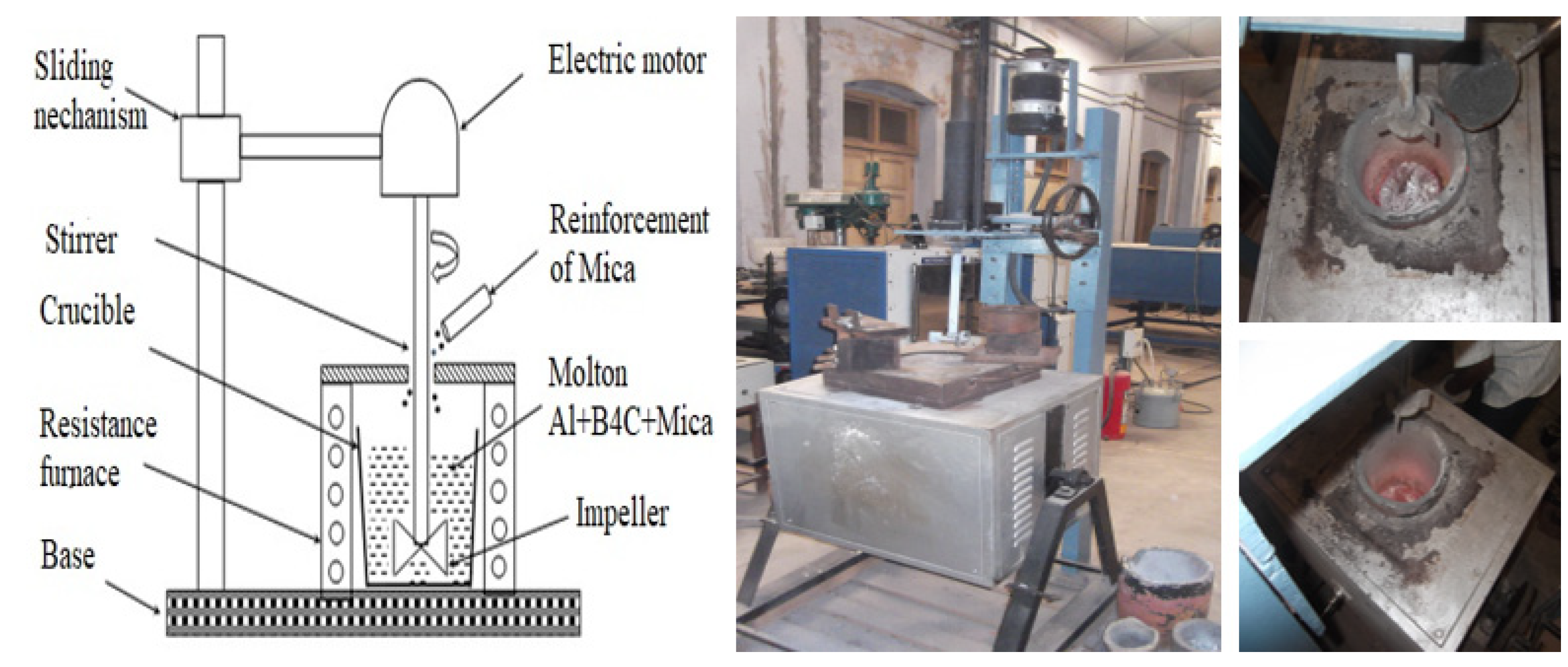
2.1. Preparation of Al/B4C/Mica Hybrid Composite Samples

The stir casting technique was adopted to ensure the even dispersal of the reinforcement particles in Al base matrix. AA6061 alloy was cut into small shards for the compatible loading into a crucible furnace. AA6061 alloy was first melted in the electrical furnace (Shanta Engineering, Chennai, India), while B4C and mica ceramic particles were concurrently preheated to 650 °C. Once the base matrix reached 750 °C, the predetermined quantity of fillers was added, and the mixture agitated uniformly at 500 rev/min for up to 5 to 7 min. The homogenized AMC was then poured to a pre-heated mould to prepare samples of 100 mm × 100 mm × 10 mm in size. The same procedure and process setting was followed for preparing samples with different combinations of ingredients (0 wt.% to 6 wt.% of mica). The stir casting setup is depicted in Figure 1. The mechanical properties of the composites are listed in Table 1 [25].

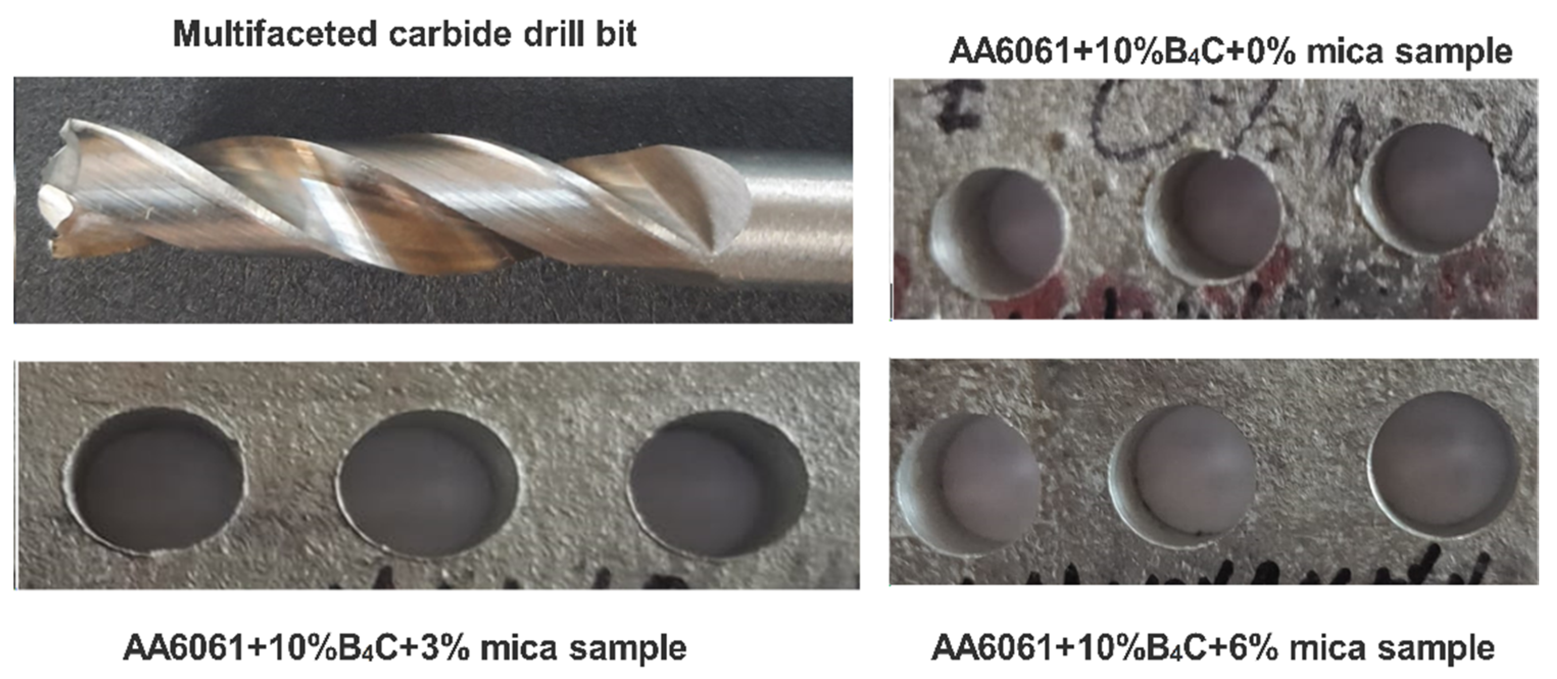
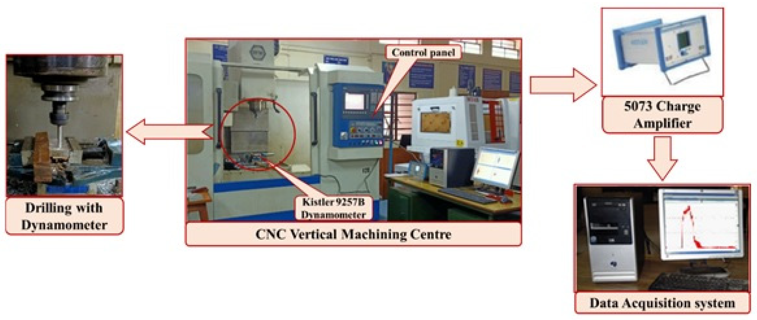
2.2. Experimentation

For drilling samples, a vertical machining centre (VMC, Bharat Fritz Werne, Bangalore, India) was used. The Al/B4C/mica AMC samples were clamped in a special fixture, which accommodates a drill tool dynamometer to measure the torque. Drilling experiments were performed with a multifaceted carbide drill bit. The specification of drill bit is helix angle = 20°, included point angle = 130°, clearance angle = 10°, diameter = 8 mm and 2 flutes. Photographs of the drill bit and drilled samples are shown in Figure 2. The thrust force and torque during drilling of AMC are significant phenomena that decide the drilling-related defects. These were measured using a 9257B type drill tool dynamometer (Kistler, India). Figure 3 depicts the setup used for measuring the thrust force and torque during drilling. The dynamometer converts the drilling forces into signals, while a 5073-charge amplifier amplifies (Kistler, India) the sensed signals and transfers them to the data acquisition system. During drilling, the cutting force dynamometer was fixed on the table and the forces acting during drilling were recorded through the DAQ. Each experiment was repeated three times to achieve consistent results.
SEM images of fabricated hybrid AMC materials are shown in Figure 4 for two different magnifications such as 100× (lower magnification) and 2000× (higher magnification) to clearly visualize the reinforced particles in the aluminium alloy matrix. Micrographs of low loaded (3 wt.%) AMC evidence more evenly distributed B4C and mica fillers. B4C is visualized as grey-colored particles and mica as grey flakes. More uniform distribution of fillers in AMC is the reason for obtaining the better modulus and strength properties [25].
Drilling experiments with different rotational spindle speeds in the range of 1000 to 3000 rpm and drill feeds in the range of 25 to 75 mm/minute were planned. To lessen the number of trials, a design of experiments (DOE) approach was used with a Box-Behnken design (BBD). Rotational spindle speed, feed rate and % of mica reinforcement was considered as three independent variables, while thrust force and torque were considered as the response variables. Table 2 illustrates the range of values used foreach input variable.
Box-Behnken design (BBD) in connection with response surface methodology (RSM) have been frequently used to understand the effects of control variables. With the standard BBD-RSM, the drilling process was evaluated for the identified input parameters. Seventeen different combination of input parameters were used in experiments and the respective thrust force and torque were measured for each experiment. No coolant was used in drilling. Three trials were performed in each experiment to confirm the repeatability. The plan of experiments as per BBD and the responses are listed in Table 3.

2.3. Response Surface Methodology (RSM)

RSM is a broadly used method to establish control factors and the process characteristics. If X 1 , X 2 and X 3 are input variables and Y 1 is the response of three input parameters:
Y 1 = f ( X 1 ) + f ( X 2 ) + f ( X 3 ) + e
In RSM, surface profile plots are used to interpret the response of inputs. Consequently, the foremost objective of RSM is to comprehend the structure of a response in relation with response zone, ridge lines, local minimum and maximum points. It examines an applicable correlation between control variables and process responses and ascertained the best optimal process variables. The experimental data were used to estimate the second order RSM models as listed below:
Thrust   force = 155.3 0.0902 A + 16.869 B 9.20833 C + 0.002012 A × B 0.0089 A × C 0.064667 B × C + 0.000047 A 2 0.10684 B 2 3.89167 C 2
Torque = 333.375 0.0753 A 0725 B 5.76667 C + 0.000614 A × B + 0.000233 A × C 0.11 B × C + 6.38 e 6 A 2 + 0.00484 B 2 2.76944 C 2

2.4. Analysis of Variance (ANOVA)

ANOVA analysis was done to evaluate the influencing input parameter on thrust force and torque (response variables). Table 4a,b shows the output of ANOVA analysis. From the analysis, p < 0.05 is obtained and hence the developed models are seen significant and comply to 95% confidence. F-value of thrust force model is 21.81, predicted R 2 = 97.7% and adjusted R 2 = 94.7%. The parameter % reinforcement is the most influencing parameter, followed by feed rate. In connection with the error term, there is no substantial inadequate fit. Toque is the force required to rotate the drilling tool against the workpiece. The torque during drilling is generated by the couple operating on the main cutting sides, while its magnitude depends on the amount of force exerted and the diameter of the tool. From ANOVA analysis, all three input variables are influencing parameters on torque. The most significant parameter is % reinforcement, followed by rotational speed. The developed model for prediction of torque is significant with p < 0.05, F = 1279.42, R 2 = 99.93%, and adjusted R 2 = 99.9%.

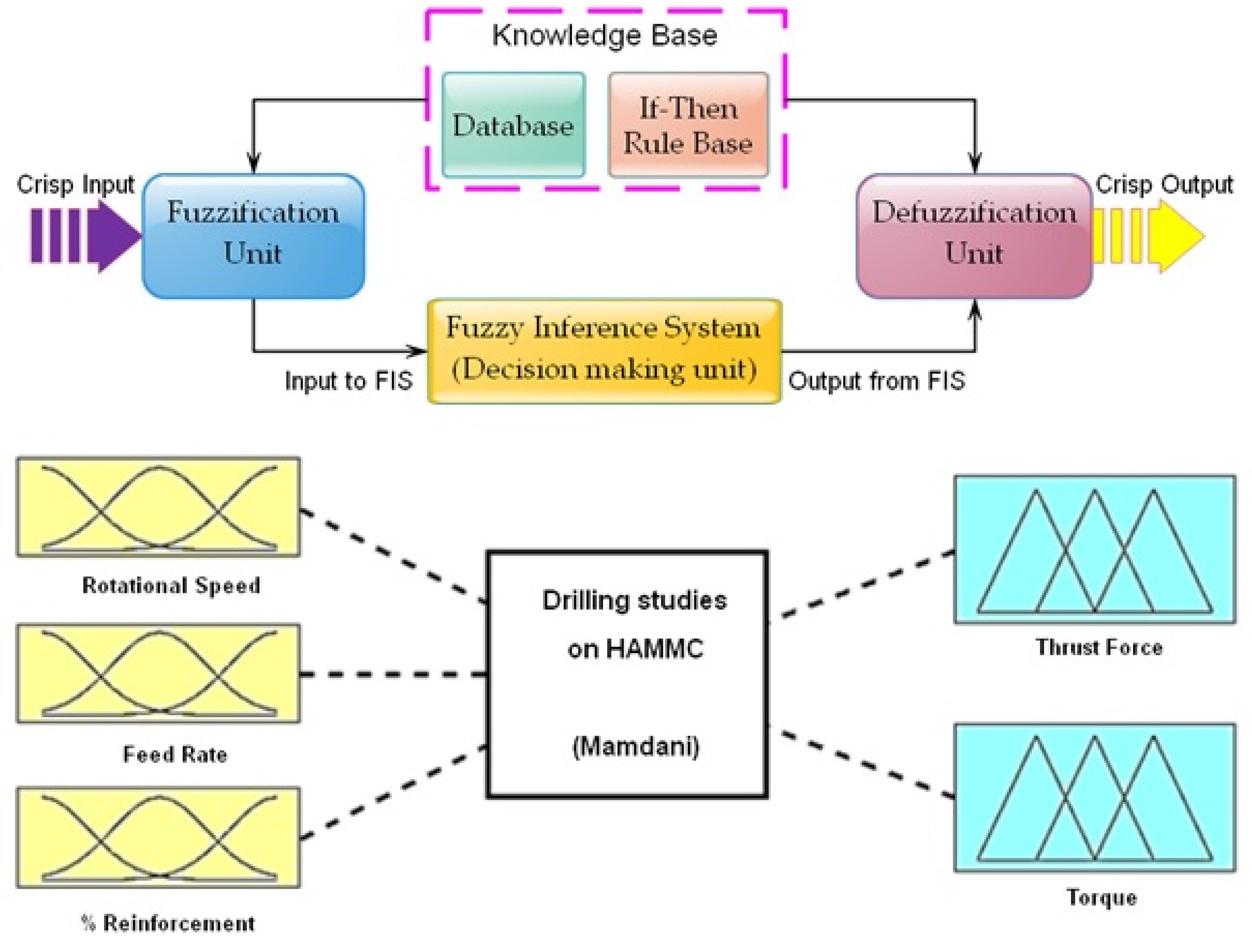
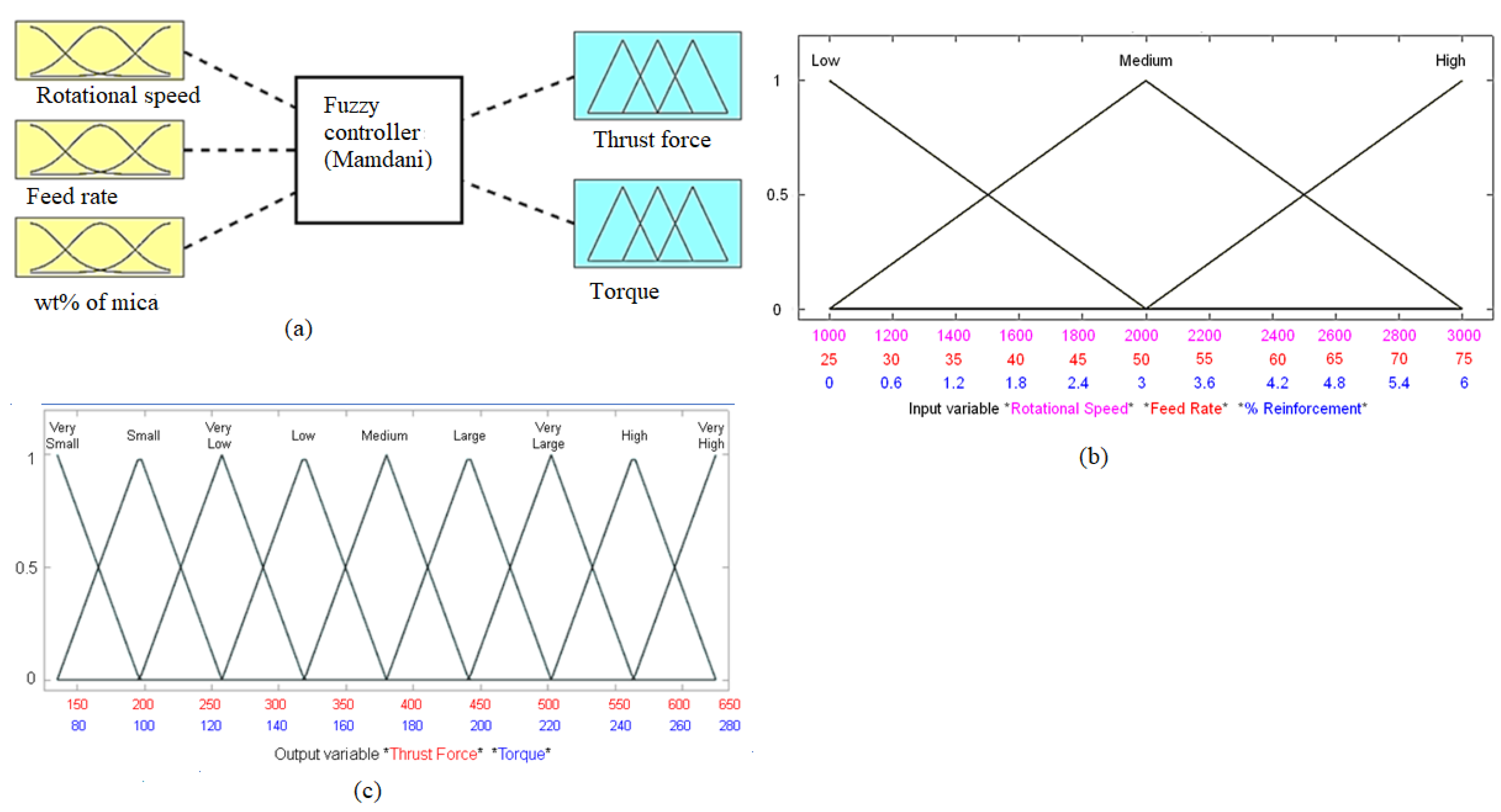
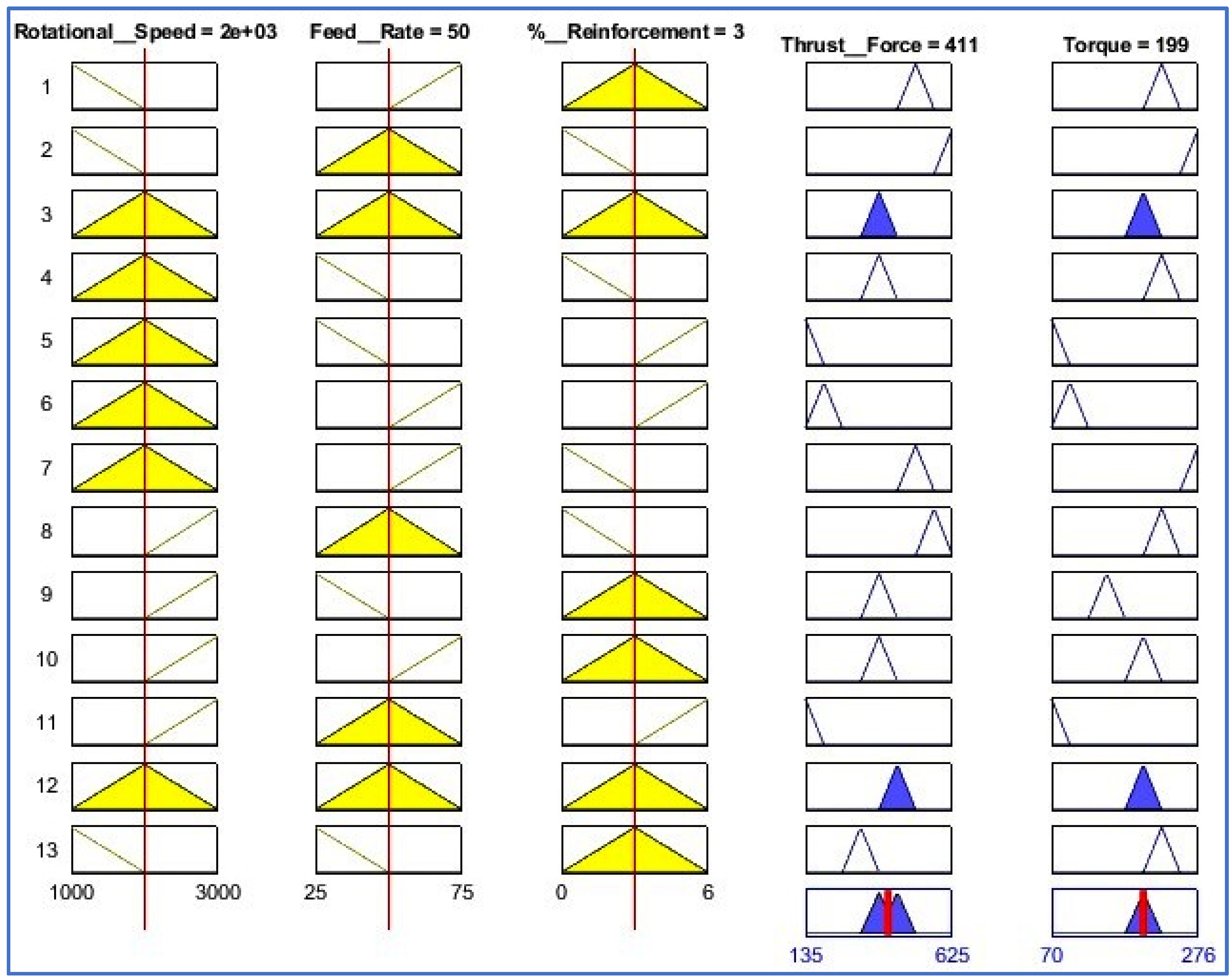
2.5. Fuzzy Interference System

A fuzzy network, also known as fuzzy intelligent system or fuzzy logic or fuzzy logic controller or fuzzy rule-based system is commonly used to map input parameters and response functions through a set of logic rules. An instruction-based fuzzy classification encompasses four modules such as rule framing, fuzzifier, implication and output processor, which are linked in succession. The response is quantitatively expressed as y = f ( x ) . The fuzzy network can be used to determine the response of any small infinitesimal input change in the network, once the rules are set for mapping input parameters and response variables. Membership function (MF) of fuzzy network is utilized in rule framing and decision making through extrapolation on the framed rules. The law-base in fuzzy inference system (FIS) consists of a set of IF-THEN rules for converting the crisp input to output. The fuzzy logic technique can be used to identify uncertainties, vagueness, lack of information and imprecision in output responses. The uncertainties existing in input data can be minimized by appropriate reasoning of FIS through proper IF-THEN rules. Accuracy of prediction model can be improved with a development of FIS using proper knowledge base and rule base. Figure 5 presents the functional elements of FIS for converting the input to crisp output using rule-base. Number of membership functions (MF) and set values depends upon the required response [26]. Sugeno and Mamdani implication methods are popular methods available in fuzzy systems.
The Mamdani inference method was considered to remove any fuzziness in experimental data. It used a max-min reference method and centroid approach for defuzzification. Figure 6 presents the fuzzy inference module and MF used in the current work. It consists of the three selected inputs (rotational speed, rate of feed and wt.% reinforcement of mica and two outputs (torque and thrust). Figure 6b depicts the triangular MFs with three subsets (Low, Medium, High) and the ranges considered for all the three input parameters. Similarly, Figure 6c depicts the triangular MFs with nine subsets (Very small, small, Very Low, Low, Medium, Large, Very Large, High, Very High) for the two output responses torque and thrust force. After assigning the range of values to MFs, rules were formed based on input and output data. The change in output and change in input were mapped by a set of rules. The rule editor as shown in Figure 7 was formed after formulating the IF-THEN rules using expert system knowledge.

2.6. Non dominated Sorting Genetic Algorithm-II (NSGA-II)

The current optimization problem is a multi-objective optimization that aims to minimize the thrust force and torque required for drilling operation [27]. NSGA-II is a metaheuristic algorithm from Kalyanmoy Deb [28]. It has been used to optimize the machining parameters for optimal solution [29]. It uses crowded distance and elitism method of assessment operators in searching of solution space. In NSGA-II, elitist strategies unite the finest descendants of the finest parents, ensuring that excellent solutions are preserved globally [30]. In the preservation of the elites, the NSGA-II generates a competitive collection of individuals, ranks them as per non-domination levels, and sorts them out to establish a new group of better descendants for the following stage. The operation of niching is performed by includingcrowding distance to individuals of newly formulated group. Crowding distance in its operator is to examine the fitness environment and maintain each individual separate from other people.
For the current simulation of identifying the optimal parameters to achieve the minimum thrust force and torque concurrently, the following parameters were set: real type of variable with population of 100, probability of a crossover as 0.9, and probability of mutation of actual parameters as1, value SBX of 10, mutation variable as100 with 100 iterations.
The formulated optimization functions are:
minimize ( thrust   force ) = f ( A , B , C )
minimize ( torque ) = f ( A , B , C )
where A , B , C are tool rotational speed, feed rate and reinforcement wt%.
The upper and lower constraints of input variables are:
1000 ≤ rotational speed ≤ 3000
25 ≤ feed rate ≤ 75
0 ≤ % reinforcement wt.% ≤ 6
A redefined weightage of w 1 = w 2 = 0.5 was applied to consider the equal preference of minimizing the thrust force and torque in the current problem.

3. Results and Discussions

3.1. Drilling Characteristics of AA6061/10 wt% B4C/Mica Composites

Drilling involves an intricate metal removing mechanism which depends on the action of speed and cutting edge of multipoint tools with diverse rake angles. The drill force acting along the direction of drill feed rate is called thrust force. During drilling of metals, the uniform thrust force is induced over a period due to the constant uncut chip thickness. The cutting edges remove the work material in the form of chip and hence affect the drilling force and torque. Drilling triggers the push-out debonding, which is caused largely by a catastrophic breakdown of the composites due to thrust force. The forces acting on the workpiece must be analysed to attain better drilling characteristics, and it must be optimized to avoid adverse effect on the drilling process.
The rotational speed of drill, drill feed rate and wt.% of reinforcement was varied at three levels. The effect of feed rate and rotational speed on thrust force is inferred in Figure 8. The effect of any single control parameter on response variable can be represented with a one factor graph, in which the response is predicted for the low (−1) and high (+1) level of input control factor. With the rise in rotational speed from 1000 rpm to 2000 rpm, the thrust force induced during drilling is decreased, but with a further increase of rotational speed above2000 rpm, there is a slight increase of thrust force observed up to 3000 rpm. This trend is due to the thermal softening of the matrix material at 2000 rpm.
Meanwhile, the thrust force is seen to progressively rise with gradual increase of tool feed rate up to 55 mm/min, after that it decreases up to 75 mm/min. This is due to the increase of shear area in the machining zone at higher drill tool feed rate [31]. Figure 9 shows the effect of the mica reinforcement on thrust force. The thrust force is decreased as the mica wt.% is increased. This is due to the lubricating nature of mica that tends to reduce the frictional force, thereby reducing the thrust force. The plot of normal probability evidences the normal distribution of residuals along a straight line hence no data transformation is needed. It is also noted that the residuals are lower and hence the prediction will be good with the developed model.
Figure 10 depicts the response surface plots of thrust force. Surface plots are 3D representations that infer the effect of any two input parameters on the response variable. Observation of Figure 10a reveals that the thrust force increases gradually with the rise of drill rotational speed and feed rate. The minimum thrust force is recorded at the modest rotational speed (2000 rpm) with lowest feed rate (25 mm/min). This trend is evidenced in one-factor analysis as well. The maximum thrust force is observed at the lowest rotational speed (1000 rpm) with highest feed rate (75 mm/min). The reason is that maximum frictional force is being induced between cutting edge and the workpiece. Observation of Figure 10b reveals that reinforcement with mica filler drastically reduces the thrust force. The maximum thrust force is observed at 0 wt.% of reinforcement with the lowest rotational speed (1000 rpm). The lowest thrust force is observed when mica reinforcement is 6 wt.% and the speed is 2000 rpm (mid-speed). Observation of Figure 10c also reveals that thrust force is rapidly decreased as the mica reinforcement increases. This is due to the self-lubrication properties of mica particles which will lower the friction between the cutting edge and work material in the machining zone. The lowest thrust force is seen at 6 wt.% of mica reinforcement and 25 mm/minute feed. From these observations we can conclude that reinforcement with mica is the key indicator for reducing the thrust force in drilling of the selected material. The best wt.% of reinforcement is 3 wt.% to 6 wt.%. Mica reinforcement improves the machinability of the fabricated AA6061/10%B4C/mica AMC material.
Figure 11 depicts one factor analysis showing the effect of rotational speed and feed rate on torque. The dotted lines represent the 95% confidence interval limits within which the analysis is performed. Increase of drill rotational speed gradually decreases the torque on the drill tool. The rise of temperature at the higher order of drill speed leads to thermal softening of the base material and hence consequently reduced torque. The minimum toque is induced when the feed rate is also lowest [32]. When the feed rate increases, contact area of cutting edge per unit time also increases, which subsequently increases the energy needed for cutting, demanding higher torque. It also induces a high frictional force between the drill cutting edge and workpiece.
High loading of mica into the hybrid composite reduces torque as shown in Figure 12, because of the lubricating behaviour of mica. It reduces friction at the contact surface of tool and workpiece drastically. The normal residual plot shown in Figure 12 infers that all residual points are located on the fitted straight line and hence the data transformation is not required. Also, all the residuals are lower as the predicted values are closer to the experimental outputs showing the supremacy of the developed mathematical model.
The generated surface plots for torque are shown in Figure 13. A non-linear relationship exists between the output and input factors is visualized from the 3D surface plot. Torque is reduced with higher drilling speed but increases substantially with a higher rate of tool feed. The lowest toque is observed at the highest rotational speed (3000 rpm) with the lowest feed rate (25 mm/min). The increase in wt.% of mica drastically decreases the induced torque. The reinforcement of mica performances as solid lubricant, lowers the friction at contact surfaces between tool, chip and work piece, thereby reduces the drilling torque. The trend observed in Figure 13 is slightly different from the surface plots shown in Figure 11. The thrust force is minimum at mid-speed (2000 rpm) with lowest feed rate, but torque is minimum at highest speed (3000 rpm) with lowest feed rate (25 mm/min).
The above investigations give some good understanding of the physics behind the drilling of this composite material. Any machining process is not just bringing two surfaces together to remove metals, but also breaking molecular bonds. This will create an incredible frictional heat between surfaces. It is obvious that the thrust force is a function of friction between tool and the workpiece. The higher the level of ceramic reinforcement, the higher the friction that will occur during the drilling and hence a higher thrust force will be observed, but a decreased thrust force is observed in this research, as the mica reinforcement helps in reducing the frictional resistance. The presence of the mica reinforcement has also helped to improve the chip breakability. The formation of chips and their breakability are some judgmental parameters of the efficiency of the machining. Serrated chips are mostly observed in this research. The formation of this kind of non-homogeneous chips is due to thermal softening of the material. Continuous chips are observed in a few conditions, particularly in low ceramic-loaded composites. The continuous chips are observed at low speeds too, as all flutes must have been in contact.
The surface morphology of drilled holes was examined using SEM images. Figure 14 depicts the morphology of holes prepared at drill speed = 2000 rpm and feed rate = 75 mm/min one under lower magnification (500×) on the left side and higher magnification (1000×) on the right side. The surface of hole in AA6061/10%B4C/0%mica sample is a little bit rough with boron carbide particles seen as black features. Some deep grooves and surface cracks are also visible. Figure 14b depicts a SEM image of the hole surface in a AA6061/10%B4C/3%mica sample. The drilled surface is characterized by deep grooves, with higher surface cracks and mica particles seen as white dots. Figure 14c isa SEM image of the hole surface in a AA6061/10%B4C/6%mica sample. It is seen that the drilled surface is free from surface cracks and grooves. A better quality of surface is achieved due to the better lubricating nature of a higher percentage of mica particles.

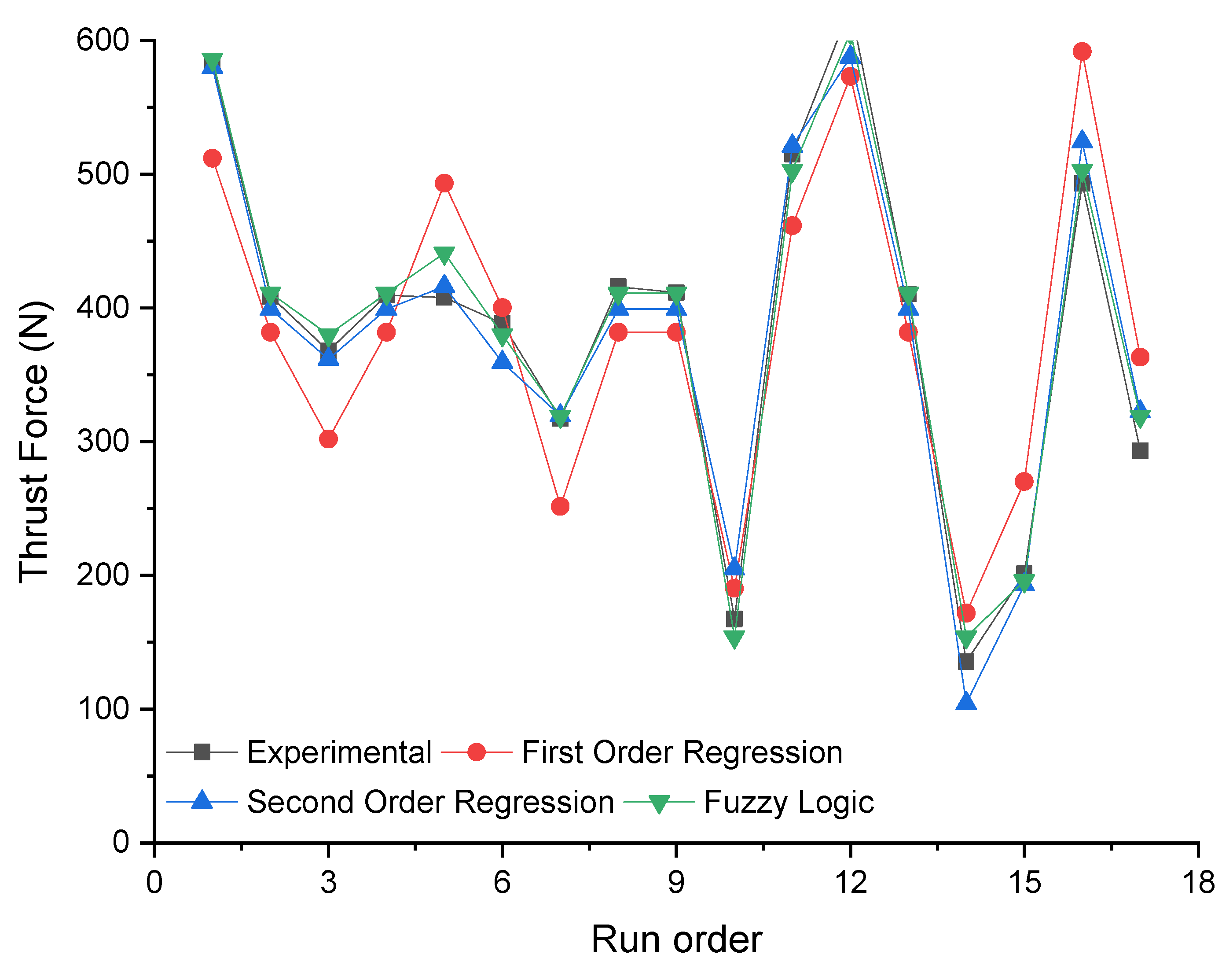
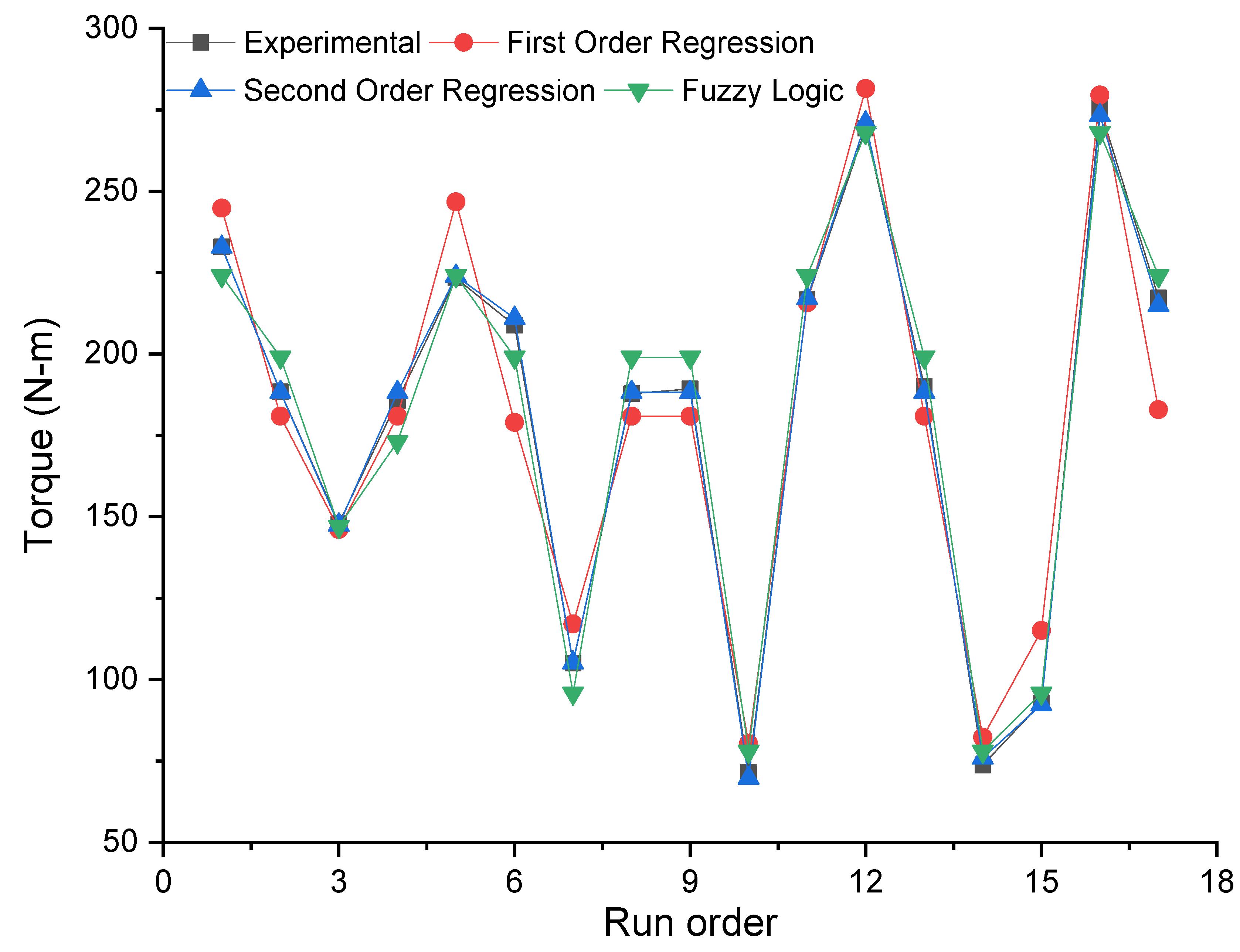
3.2. Results from Fuzzy Model and Non-Dominated Sorting Genetic Algorithm-II

The advantage of using a fuzzy model is that it can predict the responses for any small change in input. A fuzzy model was used to predict thrust force and torque based on the input condition keyed into the rule editor. Figure 15 and Figure 16 compare the experimental results, regression model results and fuzzy model results. It is found that the predictions from the fuzzy and second order RSM model are closer to the experimental results.
The NSGA II algorithm was used to predict the optimal drilling condition for obtaining the minimum thrust force and minimum torque [33]. This multi-objective optimization used equal weightage w 1 = w 2 = 0.5 [34]. Figure 17 shows iterations with respective to convergence of both objective functions. Figure 18 shows the Pareto optimal fronts of the current multi-objective optimization problem.
The optimal drilling parameters that can produce minimum thrust force of 339.68 N and torque of 68.98 Nm are rotational speed = 1840 rpm, feed rate = 25.3 mm/min and % of mica reinforcement = 5.83 wt.%. The predicted results match with the analysis results presented in Section 3.1. The NSGA-II predicted results are more accurate than the ones found in the surface plots.
The predicted results from NSGA-II were validated experimentally. AMC samples with 5.83 wt.% of mica were fabricated, and drill holes was prepared at rotational speed = 1840 rpm and feed rate = 25.3 mm/min. The thrust force and torque at drilling were measured and compared as listed in Table 5. Very minimal error (less than 0.1%) is observed between the NSGA-II predicted result and the experimental result. It is concluded from these analyses and investigations that Al/10 wt.% B4C/5.83 wt.% of mica hybrid AMC is a good choice of material for many industrial applications. It can be drilled at 1840 rpm and 25.3 mm/min, using minimal thrust force and minimal torque. This subsequently will reduce the cost of production.

4. Conclusions

Hybrid AMC was fabricated with AA6061 as base material, 10 wt.% of B4C and varying wt.% (0, 3 and 6 wt.%) of mica using a stir casting method. The presence of solid lubricant in the composite has helped to improve the machinability of the composite and surface integrity during drilling. Machinability studies were conducted through dry drilling with a Box-Behnken design (BBD) of experiments. The statistical analysis was carried out to understand the influencing parameters. The process parameters were optimized using NSGA-II and the following conclusions were drawn:
(1)
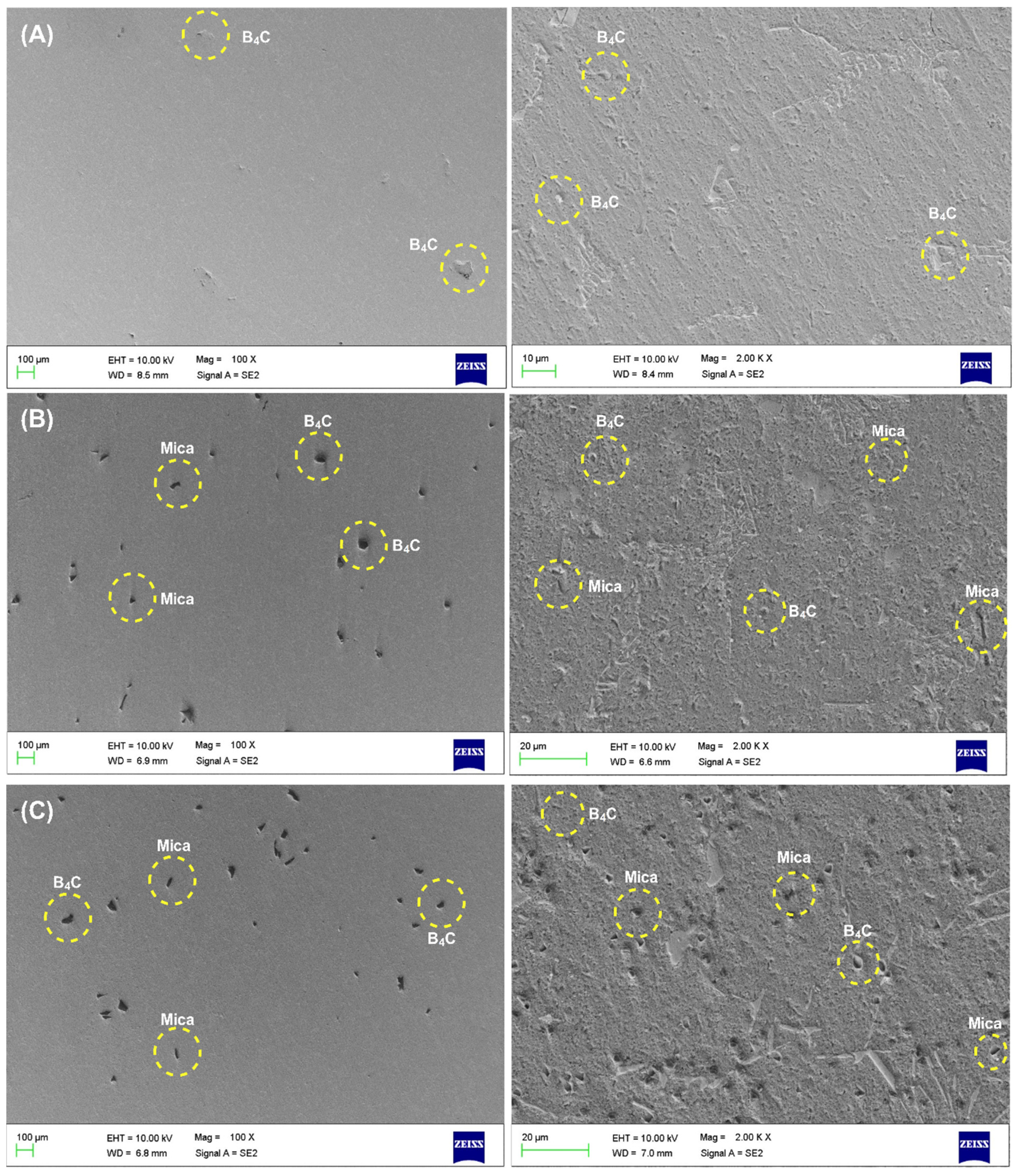
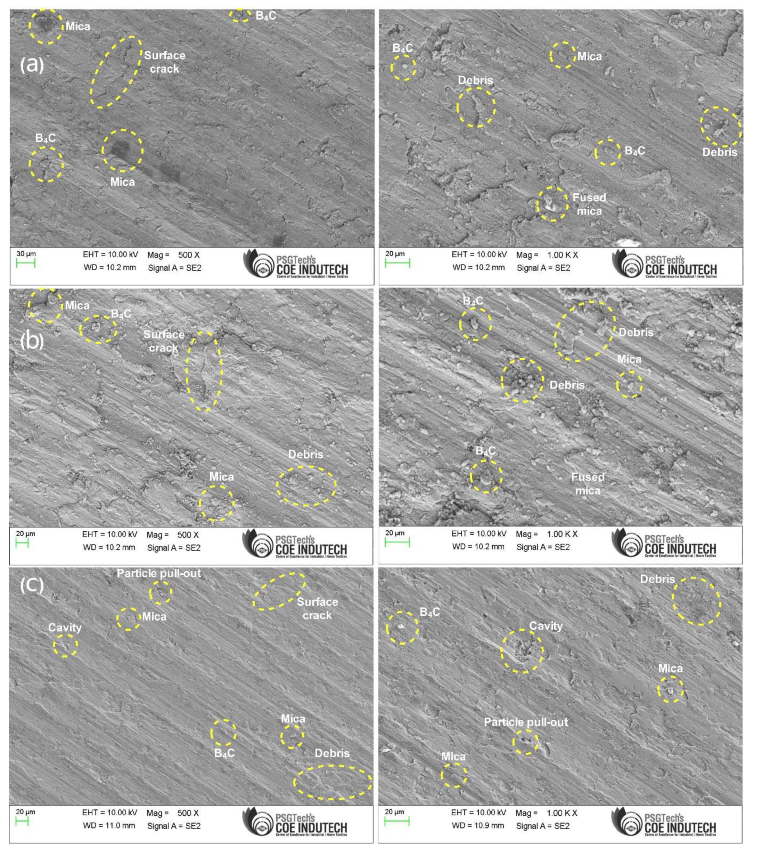
Microstructural analysis of the as-fabricated AMC shows even distribution of B4C and mica particulates in the AA6061 matrix, where B4C particles are visualized as grey particulates and mica as grey flakes.
(2)
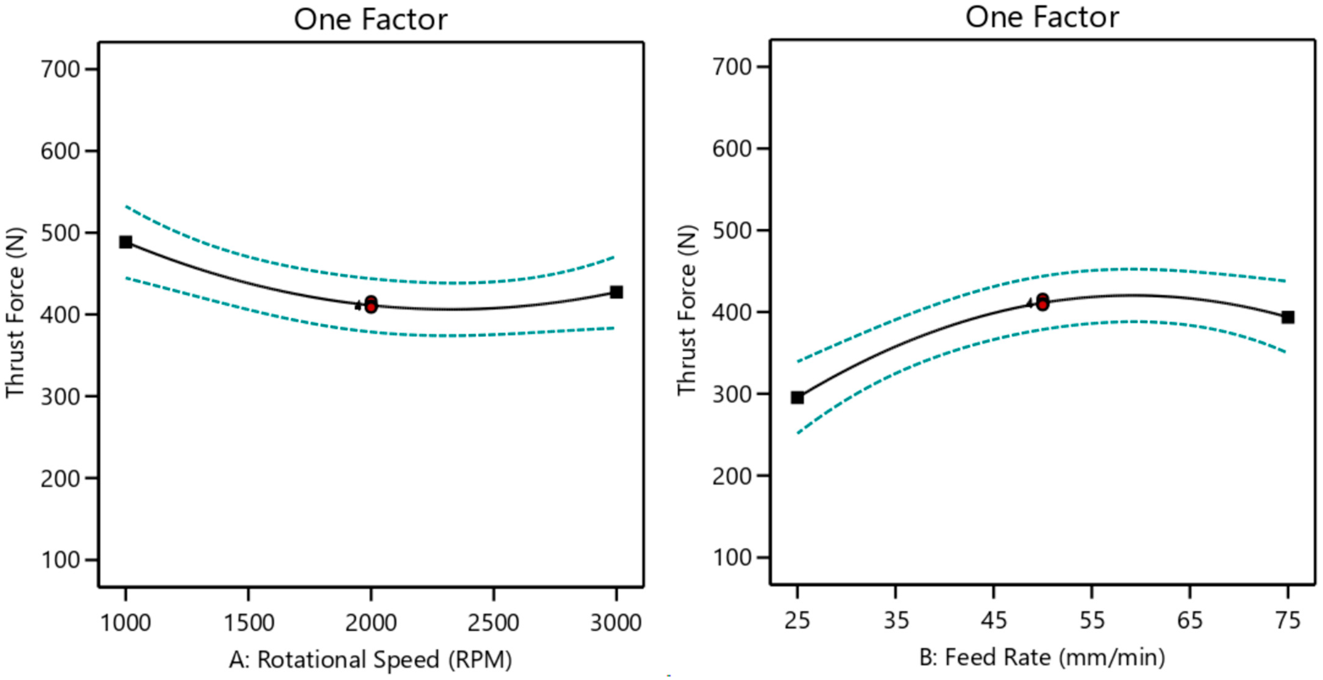
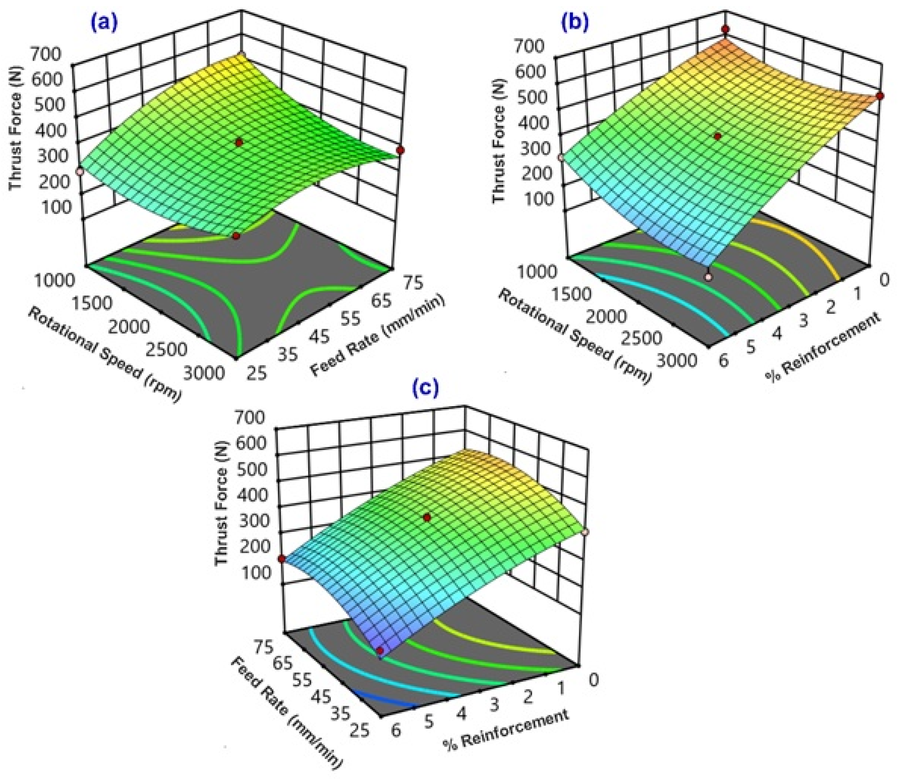
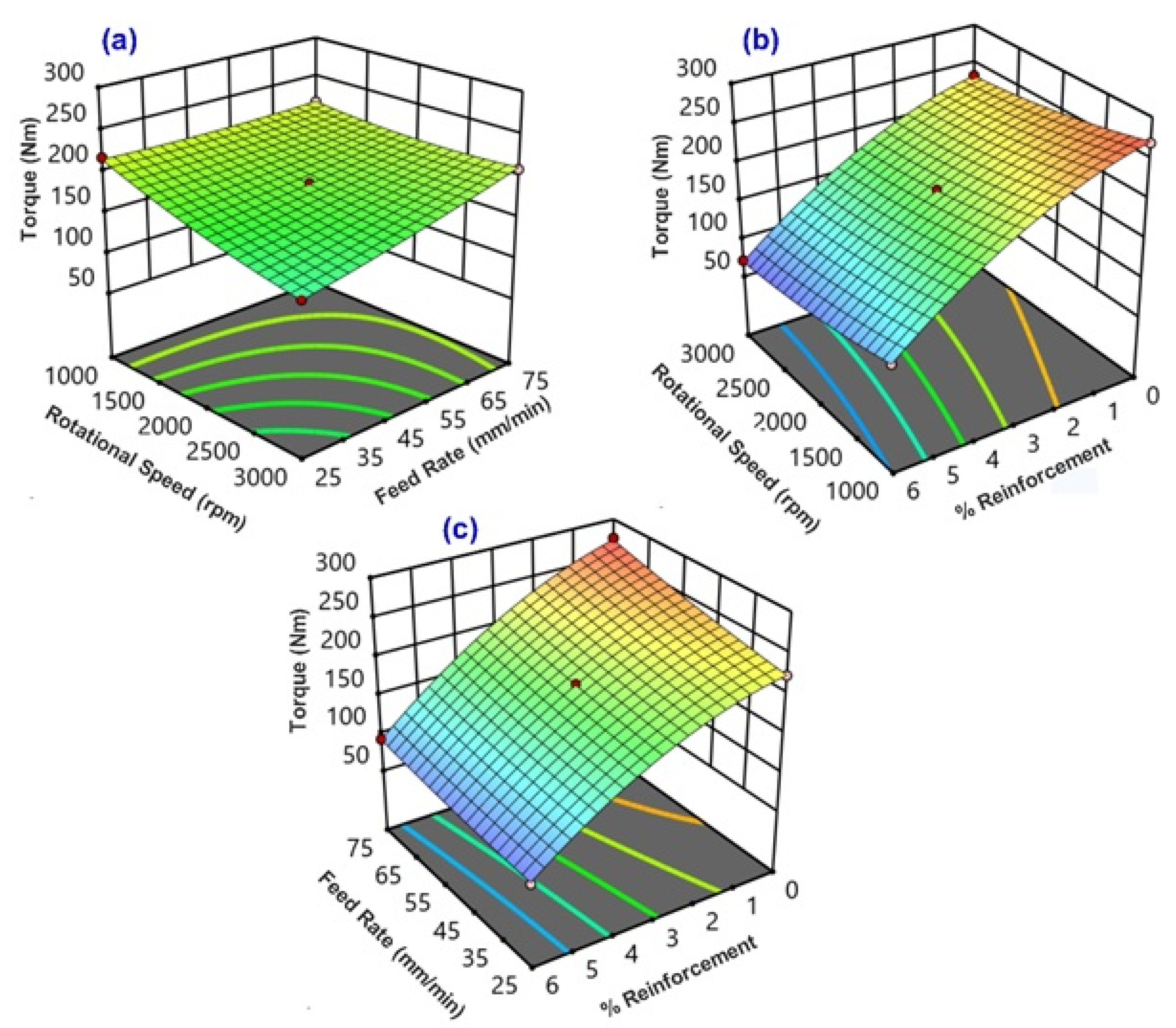
With increasing spindle speed, the induced thrust force is decreased up to 2000 rpm because of matrix phase thermal softening, whereas with a further increase of rotational speed, there is a slight rise of thrust force owing to the friction and wear on tool surface.
(3)
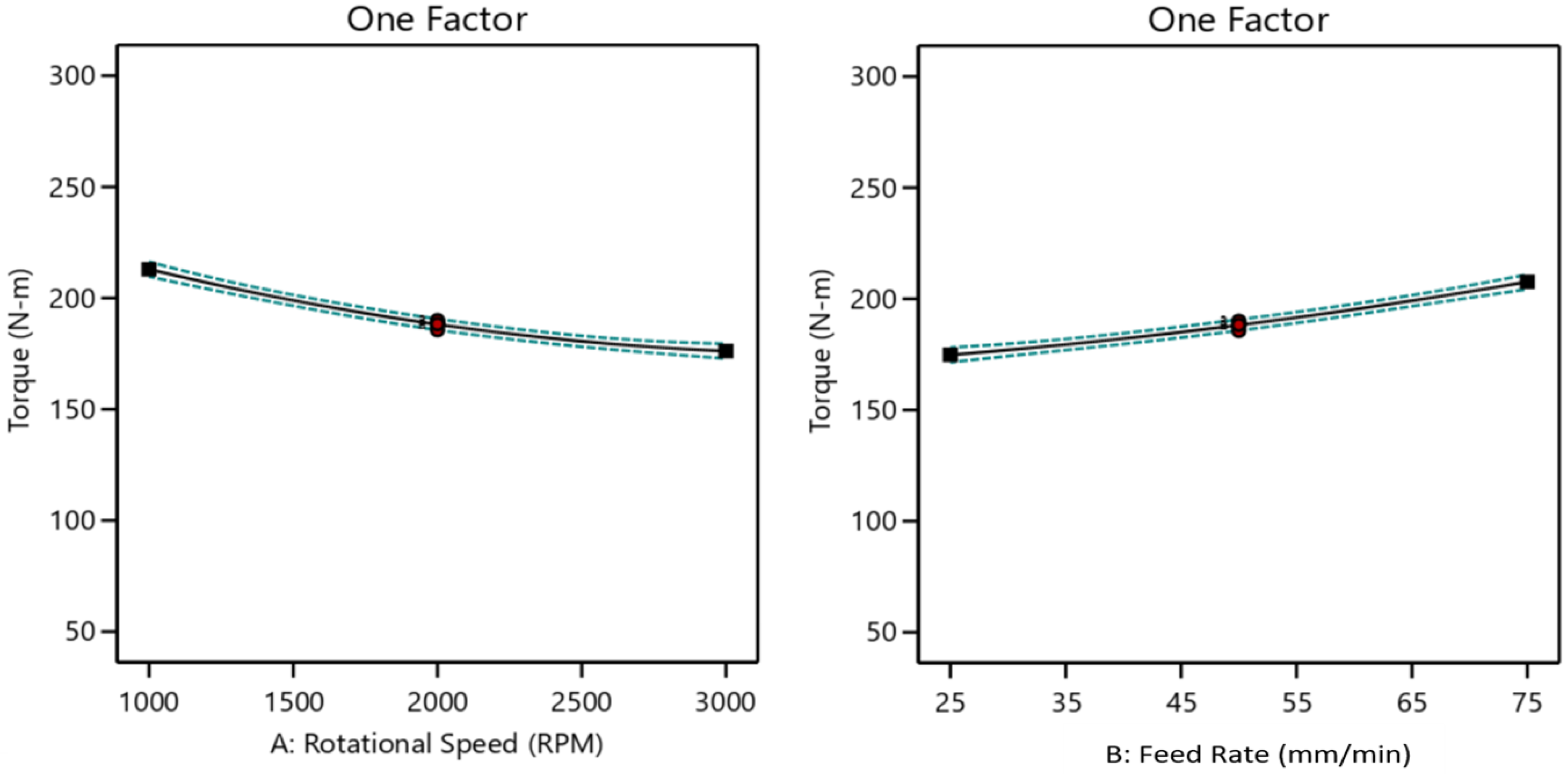
Increase of spindle speed gradually decreases the torque because of softening of matrix constituent at higher orders of cutting speed. The minimum torque is observed at the highest speed (3000 rpm).
(4)
A gradual increase of torque is ascertained with an increase in feed rate and the minimum torque is observed only at low feed rate (25 mm/min). As the feed rate increases, the contact area of cutting edge per unit time also increases, which subsequently increases the specific cutting energy.
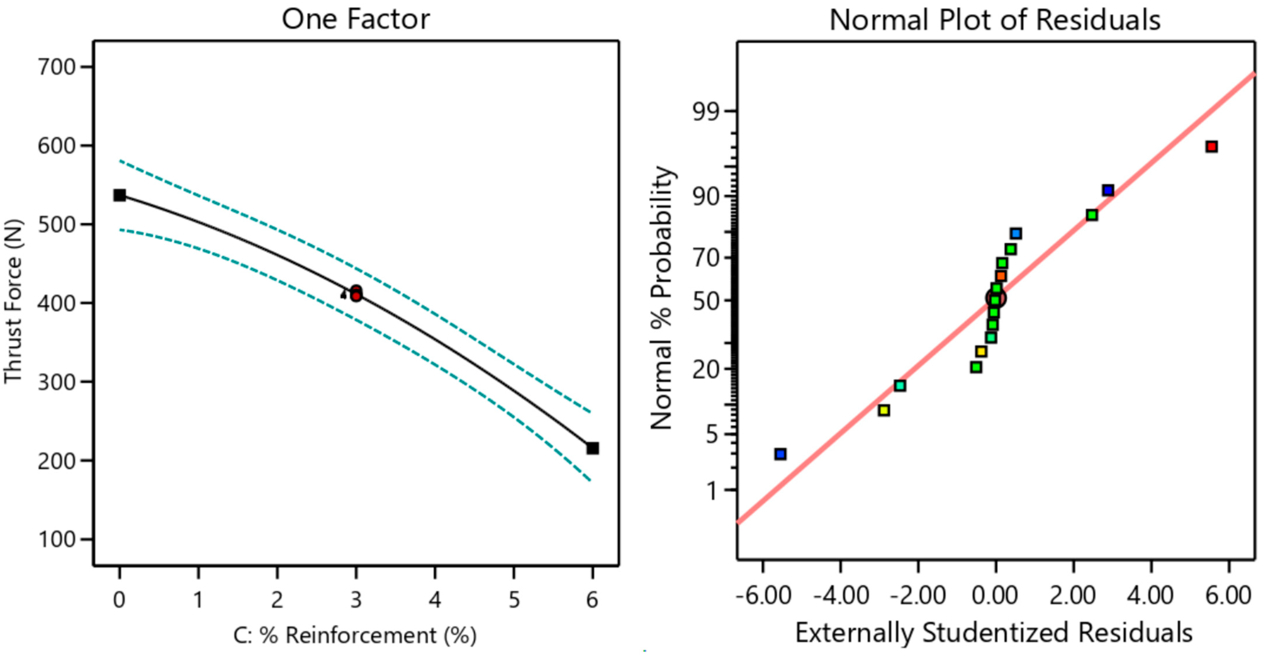
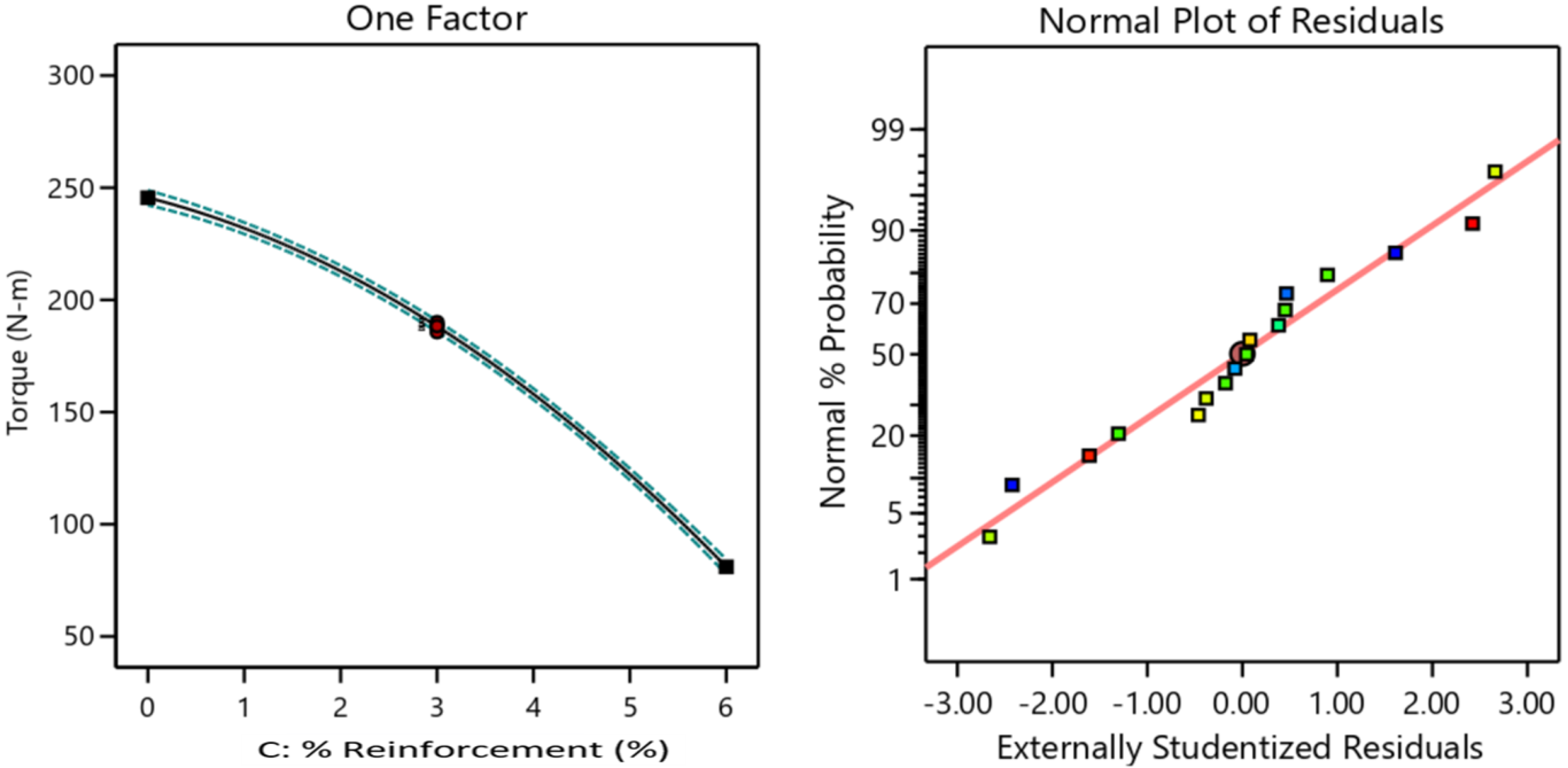
(5)
Both thrust force and torque are reduced with high loading (6 wt.%) of secondary reinforcement of mica. This is attributed by the lubricating properties of mica which reduce the friction between the tool-work and chip-tool interfaces.
(6)
It is clearly noted from SEM examinations that a high degree of surface quality is seen in AA6061 + 10% B4C + 6% Mica hybrid composite material.
(7)
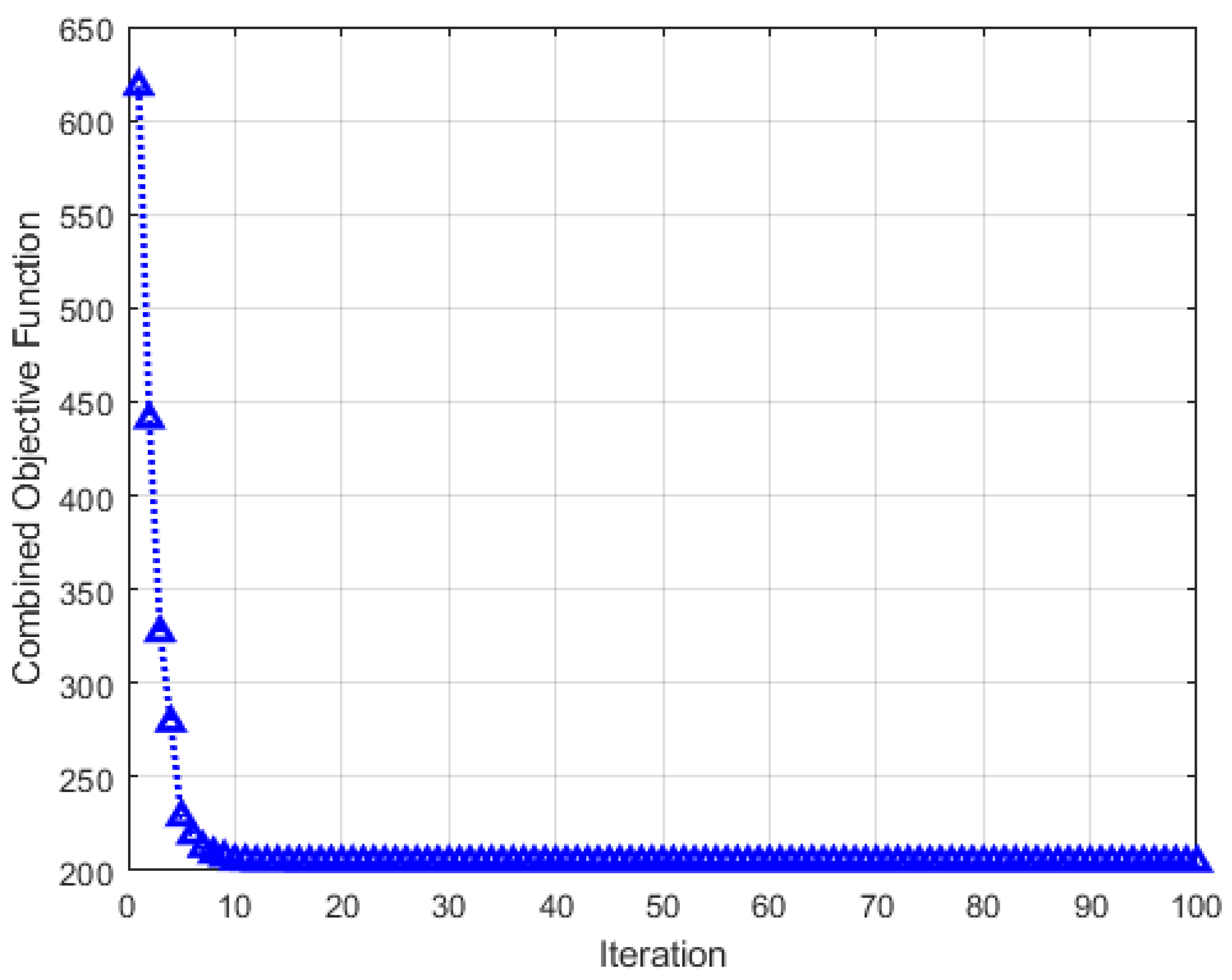
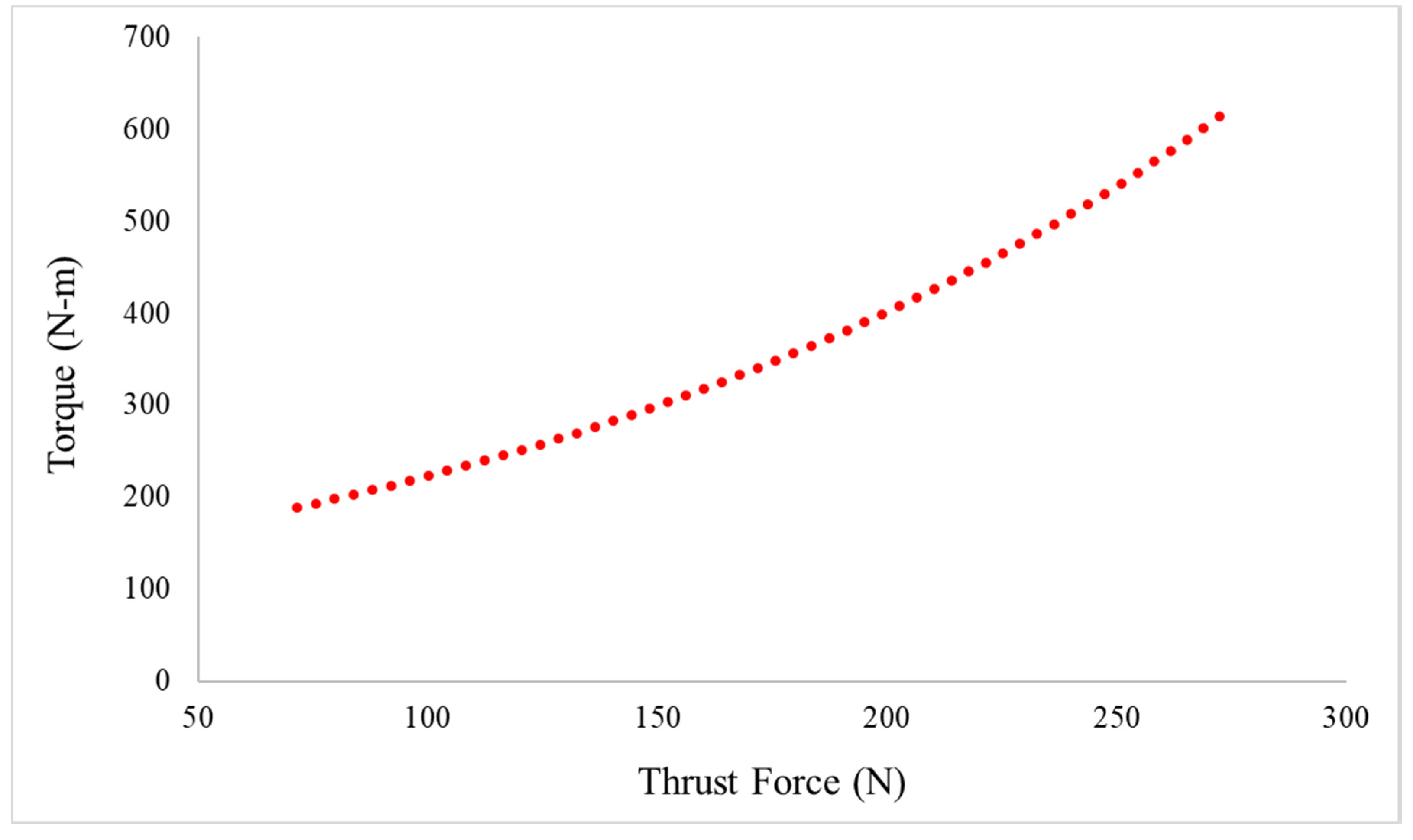
Multi-objective optimization by the NSGA-II algorithm has indicated that 1840 rpm of rotational speed, 25.3 mm/min of feed rate and 5.83% of mica reinforcement are the best parameters for obtaining the lowest thrust force of 339.68 N and torque of 68.98 N·m. The validation experimental results also confirm the predicted results with a very negligible error.

Author Contributions

Conceptualization and Supervision—P.K., Investigations and original draft writing—V.K. and S.N., Analysis, Interpretations and Editing—E.N. and K.M., Funding Acquisitions—E.N. and K.M. All authors have read and agreed to the published version of the manuscript.

Funding

This work is supported by CERVIE, UCSI University Pioneer Scientist Incentive Fund (PSIF) with Project Code of PROJ-2019-IN-FETBE-068.

Data Availability Statement

Dataset related these studies, findings and results as reported are included in the manuscript itself. It is also available from the corresponding author on reasonable request.

Conflicts of Interest

The authors declare no conflict of interest.

Nomenclature

MMCMetal matrix composite
B4CBoron carbide
GAGenetic algorithm
VMCVertical machining center
DAQData acquisition system
DOEDesign of Experiments
BBDBox-Behnken design
RSMResponse Surface Methodology
R2Regression coefficient
pprobability value
FFischer value
MFMembership function
FISFuzzy inference system
SEMScanning electron microscope
ANOVAAnalysis of Variance
AMCAluminium matrix composite
NSGA-IINon-dominated sorting genetic algorithm

References

  1. Prakash, S.; Sasikumar, R.; Natarajan, E.; Suresha, B. Influence of Feeding Techniques in Bottom Tapping Stir Casting Process for Fabrication of Alumina Nano-filler-reinforced Aluminium Composites. Trans. Indian Inst. Met. 2020, 73, 1265–1272. [Google Scholar] [CrossRef]
  2. Prakash, S.; Sasikumar, R.; Natarajan, E. Superior material properties of hybrid filler reinforced aluminium MMC through double-layer feeding technique adopted in bottom tapping stir casting. High Temp. Mater. Process. 2018, 22, 249–258. [Google Scholar] [CrossRef]
  3. Anbuchezhiyan, G.; Mohan, B.; Senthilkumar, N.; Pugazhenthi, R. Synthesis and Characterization of Silicon Nitride Reinforced Al–Mg–Zn Alloy Composites. Met. Mater. Int. 2021, 27, 3058–3069. [Google Scholar] [CrossRef]
  4. Rajmohan, T.; Palanikumar, K. Optimization of Machining Parameters for Surface Roughness and Burr Height in Drilling Hybrid Composites. Mater. Manuf. Process. 2012, 27, 320–328. [Google Scholar] [CrossRef]
  5. Kumar, P.; Chauhan, S.R.; Pruncu, C.I.; Gupta, M.K.; Pimenov, D.Y.; Mia, M.; Gill, H.S. Influence of Different Grades of CBN Inserts on Cutting Force and Surface Roughness of AISI H13 Die Tool Steel during Hard Turning Operation. Mater. 2019, 12, 177. [Google Scholar] [CrossRef] [Green Version]
  6. Abdullah, A.B.; Sapuan, S.M. Hole-Making and Drilling Technology for Composites: Advantages, Limitations and Potentials; Woodhead Publishing: Cambridge, UK, 2019. [Google Scholar]
  7. Dalavi, A.-M.; Pawar, P.-J.; Singh, T.-P.; Warke, A.-S.; Paliwal, P.-D. Review on optimization of hole-making operations for injection mould using non-traditional algorithms. Int. J. Ind. Eng. Manag. 2016, 7, 9–14. [Google Scholar]
  8. Tsao, C. The effect of pilot hole on delamination when core drill drilling composite materials. Int. J. Mach. Tools Manuf. 2006, 46, 1653–1661. [Google Scholar] [CrossRef]
  9. Rahman, M.A.; Bhuiyan, S.; Sharma, S.; Kamal, M.S.; Imtiaz, M.M.M.; AlFaify, A.; Nguyen, T.-T.; Khanna, N.; Sharma, S.; Gupta, M.K.; et al. Influence of Feed Rate Response (FRR) on Chip Formation in Micro and Macro Machining of Al Alloy. Metals 2021, 11, 159. [Google Scholar] [CrossRef]
  10. Altunpak, Y.; Ay, M.; Aslan, S. Drilling of a hybrid Al/SiC/Gr metal matrix composites. Int. J. Adv. Manuf. Technol. 2011, 60, 513–517. [Google Scholar] [CrossRef]
  11. Rajmohan, T.; Palanikumar, K.; Kathirvel, M. Optimization of machining parameters in drilling hybrid aluminium metal matrix composites. Trans. Nonferrous Met. Soc. China 2012, 22, 1286–1297. [Google Scholar] [CrossRef]
  12. Chakravarthy, V.V.K.; Rajmohan, T.; Vijayan, D.; Palanikumar, K. Sustainable Drilling of Nano SiC Reinforced Al Matrix Composites Using MQL and Cryogenic Cooling for Achieving the Better Surface Integrity. Silicon 2021. [Google Scholar] [CrossRef]
  13. Khanna, N.; Agrawal, C.; Gupta, M.K.; Song, Q. Tool wear and hole quality evaluation in cryogenic Drilling of Inconel 718 superalloy. Tribol. Int. 2020, 143, 106084. [Google Scholar] [CrossRef]
  14. Kumar, C.R.; Jaiganesh, V.; Malarvannan, R.R.R. Optimization of drilling parameters in hybrid (Al6061/SiC/B4C/talc) composites by grey relational analysis. J. Braz. Soc. Mech. Sci. Eng. 2019, 41, 155. [Google Scholar] [CrossRef]
  15. Prakash, J.U.; Rubi, C.S.; Rajkumar, C.; Juliyana, S.J. Multi-objective drilling parameter optimization of hybrid metal matrix composites using grey relational analysis. Mater. Today Proc. 2021, 39, 1345–1350. [Google Scholar] [CrossRef]
  16. Gajalakshmi, K.; Senthilkumar, N.; Prabu, B. Multi-response optimization of dry sliding wear parameters of AA6026 using hybrid gray relational analysis coupled with response surface method. Meas. Control 2019, 52, 540–553. [Google Scholar] [CrossRef]
  17. Subba Rao, C.V.; Sesha Rao, Y.; Marimuthu, P.; Jeyapaul, R.; Kalyan Chakravarthy, N.S.; Murugesan, P. Optimisation of Drilling Parameters of Metal Matrix Composites using Genetic Algorithm in the Taguchi Method. IOP Conf. Ser. Mater. Sci. Eng. 2021, 1126, 012035. [Google Scholar]
  18. Xiong, Y.; Wang, W.; Jiang, R.; Lin, K. A Study on Cutting Force of Machining In Situ TiB2 Particle-Reinforced 7050Al Alloy Matrix Composites. Metals 2017, 7, 197. [Google Scholar] [CrossRef] [Green Version]
  19. Parasuraman, S.; Elamvazuthi, I.; Kanagaraj, G.; Natarajan, E.; Pugazhenthi, A. Assessments of Process Parameters on Cutting Force and Surface Roughness during Drilling of AA7075/TiB2 In Situ Composite. Materials 2021, 14, 1726. [Google Scholar] [CrossRef]
  20. Al-Tameemi, H.; Al-Dulaimi, T.; Awe, M.; Sharma, S.; Pimenov, D.; Koklu, U.; Giasin, K. Evaluation of Cutting-Tool Coating on the Surface Roughness and Hole Dimensional Tolerances during Drilling of Al6061-T651 Alloy. Materials 2021, 14, 1783. [Google Scholar] [CrossRef]
  21. Aamir, M.; Giasin, K.; Tolouei-Rad, M.; Din, I.U.; Hanif, M.; Kuklu, U.; Pimenov, D.; Ikhlaq, M. Effect of Cutting Parameters and Tool Geometry on the Performance Analysis of One-Shot Drilling Process of AA2024-T3. Metals 2021, 11, 854. [Google Scholar] [CrossRef]
  22. Habib, N.; Sharif, A.; Hussain, A.; Aamir, M.; Giasin, K.; Pimenov, D.; Ali, U. Analysis of Hole Quality and Chips Formation in the Dry Drilling Process of Al7075-T6. Metals 2021, 11, 891. [Google Scholar] [CrossRef]
  23. Durão, L.M.P.; Tavares, J.M.R.S.; De Albuquerque, V.H.C.; Marques, J.F.S.; Andrade, Ó.N.G. Drilling Damage in Composite Material. Materials 2014, 7, 3802–3819. [Google Scholar] [CrossRef] [Green Version]
  24. Hassan, M.; Abdullah, J.; Franz, G.; Shen, C.; Mahmoodian, R. Effect of Twist Drill Geometry and Drilling Parameters on Hole Quality in Single-Shot Drilling of CFRP/Al7075-T6 Composite Stack. J. Compos. Sci. 2021, 5, 189. [Google Scholar] [CrossRef]
  25. Velavan, K.; Palanikumar, K.; Natarajan, E.; Lim, W.H. Implications on the influence of mica on the mechanical properties of cast hybrid (Al+10%B4C+Mica) metal matrix composite. J. Mater. Res. Technol. 2021, 10, 99–109. [Google Scholar] [CrossRef]
  26. Ponnuvel, S.; Senthilkumar, N. A study on machinability evaluation of Al-Gr-B4C MMC using response surface methodology-based desirability analysis and artificial neural network technique. Int. J. Rapid Manuf. 2019, 8, 95. [Google Scholar] [CrossRef]
  27. Datta, R.; Deb, K. A classical-cum-Evolutionary Multi-objective optimization for optimal machining parameters. In Proceedings of the World Congress on Nature and Biologically Inspired Computing, Coimbatore, India, 9–11 December 2009; pp. 607–612. [Google Scholar] [CrossRef]
  28. Datta, R.; Majumder, A. Optimization of turning process parameters using Multi-objective Evolutionary algorithm. In Proceedings of the IEEE Congress on Evolutionary Computation, Barcelona, Spain, 18–23 July 2010; pp. 1–6. [Google Scholar] [CrossRef]
  29. Deb, K.; Datta, R. Hybrid Evolutionary Multi-Objective Optimization of Machining Parameters, KanGAL Report No. 99002; Indian Institute of Technology: New Delhi, India, 2011; pp. 1–23. [Google Scholar]
  30. Zhang, H.; Liu, Y.; Liu, C. Multi-Objective Parameter Optimization for Cross-Sectional Deformation of Double-Ridged Rectangular Tube in Rotary Draw Bending by Using Response Surface Methodology and NSGA-II. Metals 2017, 7, 206. [Google Scholar] [CrossRef]
  31. Xu, J.; Huang, X.; Chen, M.; Davim, J.P. Drilling characteristics of carbon/epoxy and carbon/polyimide composites. Mater. Manuf. Process. 2020, 35, 1732–1740. [Google Scholar] [CrossRef]
  32. Palanikumar, K. Experimental investigation and optimisation in drilling of GFRP composites. Measurement 2011, 44, 2138–2148. [Google Scholar] [CrossRef]
  33. Natarajan, E.; Kaviarasan, V.; Lim, W.H.; Tiang, S.S.; Parasuraman, S.; Elango, S. Non-dominated sorting modified teaching–learning-based optimization for multi-objective machining of polytetrafluoroethylene (PTFE). J. Intell. Manuf. 2020, 31, 911–935. [Google Scholar] [CrossRef]
  34. Suresh, S.; Elango, N.; Venkatesan, K.; Lim, W.H.; Palanikumar, K.; Rajesh, S. Sustainable friction stir spot welding of 6061-T6 aluminium alloy using improved non-dominated sorting teaching learning algorithm. J. Mater. Res. Technol. 2020, 9, 11650–11674. [Google Scholar] [CrossRef]
Figure 1. Stir casting setup used.
Metals 11 02060 g001
Figure 2. Drill tool and drilled samples of different compositions.
Metals 11 02060 g002
Figure 3. Experimental setup measuring thrust force and torque during drilling.
Metals 11 02060 g003
Figure 4. SEM images of fabricated composites (1000×). (A) 90 wt.% Al/10 wt.% B4C/0 wt.% mica (B) 87 wt.% Al/10 wt.% B4C/3 wt.% mica. (C) 84 wt.% Al/10% B4C + 6% mica.
Metals 11 02060 g004
Figure 5. Functional elements of fuzzy interference system used in this research.
Metals 11 02060 g005
Figure 6. (a) Fuzzy inference system model (b) Triangular membership function with 3 subsets for inputs (c) Triangular membership function with 9 subsets for outputs.
Metals 11 02060 g006
Figure 7. Rule editor representing the developed Fuzzy inference system.
Metals 11 02060 g007
Figure 8. Effect of rotational speed and feed rate on thrust force.
Metals 11 02060 g008
Figure 9. Effect of reinforcement on thrust force and normal probability plot.
Metals 11 02060 g009
Figure 10. Response surface plots of thrust force (a) rotational speed, feed rate vs. thrust force (b) rotational speed, % reinforcement of mica vs. thrust force and (c) feed rate, % reinforcement of mica vs. thrust force.
Metals 11 02060 g010
Figure 11. Effect of rotational speed and feed rate on torque.
Metals 11 02060 g011
Figure 12. Effect of reinforcement and normal probability plot for torque.
Metals 11 02060 g012
Figure 13. Response surface plot for torque (a) rotational speed, feed rate vs. torque (b) rotational speed, % reinforcement of mica vs. torque and (c) feed rate, % reinforcement of mica vs. torque.
Metals 11 02060 g013
Figure 14. SEM images of drilled holes at A = 2000 rpm, B = 75 mm/min. (a) 0 wt.% of mica, (b) 3 wt.% of mica, (c) 6 wt.% of mica.
Metals 11 02060 g014
Figure 15. Comparison of experimental and predicted values of thrust force.
Metals 11 02060 g015
Figure 16. Comparison of experimental and predicted values of torque.
Metals 11 02060 g016
Figure 17. Attainment of combined objective function value during execution.
Metals 11 02060 g017
Figure 18. Pareto optimal fronts.
Metals 11 02060 g018
Table 1. Material properties of the composite materials [25].
Composite MaterialTensile Strength
(MPa)
Yield Strength
(MPa)
Micro Hardness
(HV)
Bending Strength
(MPa)
AA6061 + 10% B4C + 0% Mica139.33127.0051.092.62
AA6061 + 10% B4C + 3% Mica147.00106.6759.873.6
AA6061 + 10% B4C + 6% Mica132.6772.0053.142.95
Table 2. Input process variables.
ParameterSymbolUnits−1 Level+1 Level−alpha+alpha
Rotational SpeedArpm10003000−1+1
Feed RateBmm/min2575−1+1
% of mica ReinforcementC%06−1+1
Table 3. Box-Behnken Design (BBD) of Experiments and their results.
Serial NumberStd. Order NumberRotational Speed (A)Feed Rate (B)Mica Particles (C)Thrust ForceTorque
(rpm)(mm/min)(%)(N)(N-m)
183000500581.9232.9
2172000503408.6188.3
3113000253367.9147.9
4132000503409.5185.6
562000250407.8223.3
6103000753388.4208.7
791000506317.3105.0
8122000503415.9187.8
912000503411.6189.2
1043000506167.571.4
1151000753515.0216.6
12151000500624.9269.3
13162000503410.4190.1
1472000256135.473.7
1532000756201.392.8
1622000750493.1275.4
17141000253293.3217.2
Table 4. (a) ANOVA analysis on the effect of input variables on thrust force. (b) ANOVA analysis on the effect of input variables on torque.
(a)
SourceSum ofDoFMeanF-Valuep-Value
Model278,880.3547930,986.7060832.576680796.76566 × 10−5Significant
A-Rotational Speed7490.8817490.887.8752483720.026285721
B-Feed Rate19,345.445119,345.44520.338089020.00276576
C-% Reinforcement206,788.8051206,788.805217.39945111.57957 × 10−6
AB10,120.36110,120.3610.639650960.01382906
AC2851.5612851.562.9978778530.12698369
BC94.09194.090.09891790.76229904
A29192.52894719192.5289479.6642114990.017111594
B218,774.31842118,774.3184219.737657070.00299789
C25165.26578915165.2657895.4303033820.052590577
Residual6658.357951.1928571
Lack of Fit6625.8132208.603333271.49395624.47089 × 10−5Not Significant
Pure Error32.5448.135
Cor Total285,538.704716
Std. Dev.30.84141464 R-sq0.976681445
Mean385.2823529 Adjusted R-sq0.946700446
C.V. %8.004886392 Predicted R-sq0.628548417
Adeq Precision20.43075896
(b)
SourceSum ofDoFMeanF-Valuep-Value
Model62,944.8296993.8691279.4222.06 × 10−10Significant
A-Rotational Speed2708.4812708.48495.47529.34 × 10−8
B-Feed Rate2158.24512158.245394.81812.04 × 10−7
C-% Reinforcement54,120.5154120.59900.5232.73 × 10−12
AB942.491942.49172.41423.47 × 10−6
AC1.9611.960.3585520.568175
BC272.251272.2549.8040.000201
A2171.11841171.118431.303510.00082
B238.52895138.528957.0482850.03271
C22615.81312615.813478.52321.05 × 10−7
Residual38.26575.466429
Lack of Fit26.72538.9083333.0878110.152281Not Significant
Pure Error11.5442.885
Cor Total62,983.0916
Std. Dev.2.338039 R-sq0.999392
Mean180.8941 Adjusted R-sq0.998611
C.V. %1.292491 Predicted R-sq0.992925
Adeq Precision113.4986
ANOVA: analysis of variance; DoF: degree of freedom.
Table 5. Comparison of NSGA-II predicted results and validation results.
Drilling Parameters: Rotational Speed (A) = 1840 rpm and Feed Rate = 25.3 mm/min, % Reinforcement = 5.83 wt.%
NSGA-II Predicted ResultsResults from Validation ExperimentsError (%)
Thrust force = 339.68 N and Torque = 68.98 N·mThrust force = 340 N and Torque = 69.2 N·mLess than 0.1%
Publisher’s Note: MDPI stays neutral with regard to jurisdictional claims in published maps and institutional affiliations.

