Article

Friction Stir Processing of Additively Manufactured Ti-6Al-4V Alloy: Structure Modification and Mechanical Properties

Institute of Strength Physics and Materials Science, Siberian Branch of Russian Academy of Sciences, 634055 Tomsk, Russia
*
Author to whom correspondence should be addressed.
Submission received: 2 December 2021 / Revised: 21 December 2021 / Accepted: 24 December 2021 / Published: 27 December 2021
(This article belongs to the Special Issue Light Metals and Their Composites)

Abstract

:
This work explores the possibility of using friction stir processing to harden the Ti-6Al-4V titanium alloy material produced by wire-feed electron beam additive manufacturing. For this purpose, thin-walled workpieces of titanium alloy with a height of 30 cm were printed and, after preparation, processed with an FSW-tool made of heat-resistant nickel-based superalloy ZhS6U according to four modes. Studies have shown that the material structure and properties are sensitive to changes in the tool loading force. In contrast, the additive material’s processing direction, relative to the columnar grain growth direction, has no effect. It is shown that increasing the axial load leads to forming a 𝛽-transformed structure and deteriorates the material strength. At the same time, compared to the additive material, the ultimate tensile strength increase during friction stir processing can achieve 34–69%.

1. Introduction

Titanium alloys are essential structural materials in various industrial applications. Due to their physical and mechanical properties, titanium alloys are used in aircraft, spacecraft and automotive industries [1,2,3]. For example, titanium and its alloys manufacture airframes, high-pressure spherical tanks, rotors, gas turbine and fan blades and other products [4,5,6,7]. Recently, various additive manufacturing methods are often used to manufacture parts from different materials, which significantly reduce lead time and decrease raw material costs by producing near-net-shaped products [8]. Moreover, while for medical purposes, the main methods used were based on the use of metal powders, for the aerospace industries, the methods of direct deposition with the wire feedstock are the most appropriate [9]. Such methods include wire + arc additive manufacturing and wire-feed electron beam additive manufacturing (electron beam freeform fabrication) [10,11]. The critical difference between these technologies is the environment in which 3D printing occurs. In arc technology, the products are printed in an atmosphere of protective gas, while electron beam printing takes place in a vacuum [12]. As a result of additive manufacturing, the products have a specific structure, mainly represented by elongated columnar grains of primary 𝛽-phase [13]. This type of structure, and temperature gradients arising in the 3D printing process, lead to structural heterogeneity and anisotropy of mechanical properties in different directions, which on average is about 5% [14]. Researchers have studied various thermal and mechanical effects methods to improve the characteristics of additively manufactured materials after 3D printing. As shown in [15,16], heat treatment does not always provide the required mechanical properties, as one often has to sacrifice ductility for the sake of high strength and vice versa. The rolling procedure [17] makes it possible to reduce the grain size in products. Still, it is rather challenging to implement the technology, especially in the case of electron-beam additive manufacturing (EBAM), when the working space inside the vacuum chamber is limited. One promising processing method that can improve the structure and properties of additively manufactured products is friction stir processing (FSP) [18]. This method is often used for local hardening of materials, formation of metal matrix composites and other purposes [19]. FSP is mainly used for processing aluminum, copper and magnesium alloys [19,20,21]. However, this technology can also be applicable for titanium alloys, which proves the successful application of friction stir welding to produce welded joints from sheets of titanium and its alloys [22]. With the successful implementation of friction stir welding, it is possible to extend this approach to processing and friction stir additive manufacturing [23,24,25]. Nevertheless, the welding and processing of rolled sheets must differ significantly from the processing of additive material due to such features as anisotropy of structure and properties. For example, in [26], it was observed that at friction stir processing of EBAM’ed aluminum alloy AA5356, columnar grains formed due to high temperature gradients affecting material properties and the processing parameter selection. Using the FSP, it was possible to increase the strength of the additive alloy AA5356 by 36%, although there were defects in the workpiece. Thus, to evaluate the applicability of friction stir processing technology to additively manufactured titanium alloys, it is necessary to study the specifics of modifying the initial structure of workpieces during FSP and its influence on the formation of defects and mechanical properties in the processed area.

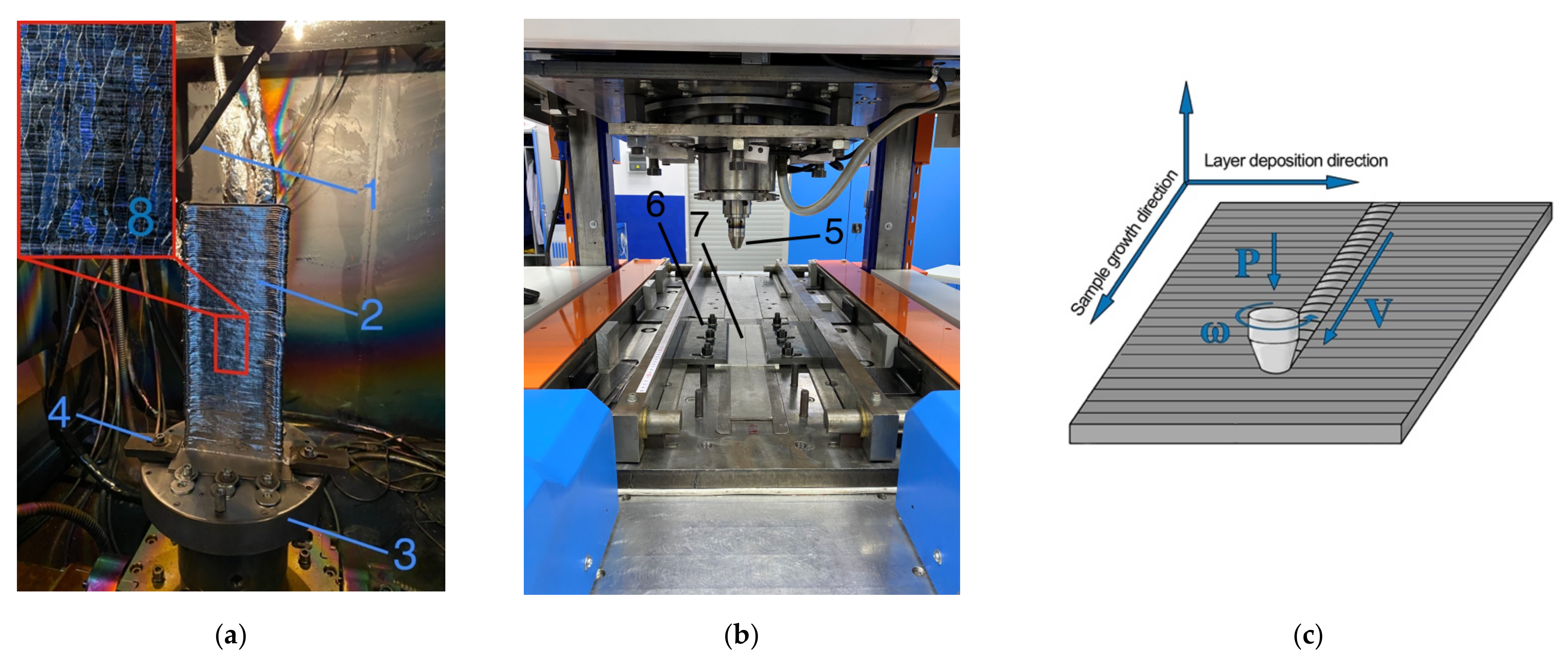
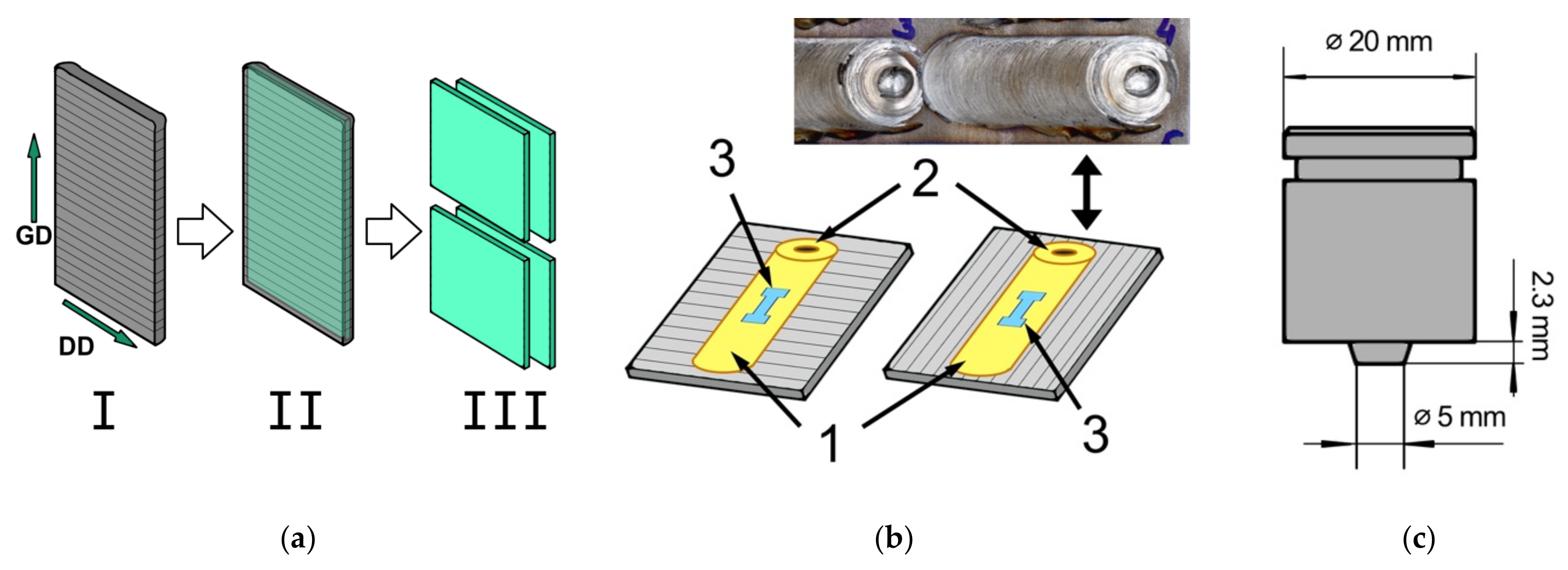
2. Materials and Methods

For these studies, friction stir processing was applied to additively-manufactured workpieces of Ti-6Al-4V titanium alloy. The vertical wall-shaped titanium alloy workpieces were fabricated by wire-feed electron beam additive manufacturing on special equipment (ISPMS SB RAS, Tomsk, Russia), shown in Figure 1a. A 2.0 mm diameter wire was used as a feedstock. The parameters of the wire-feed EBAM process, shown in Table 1, were experimentally selected to build the wall-shaped sample without external defects. The target dimensions of the additive workpieces were 300 mm in height, 120 mm in length, and 8 mm in width. After 3D printing, 2.5 mm thick plates were cut from the produced walls, which were subsequently subjected to friction stir processing (Figure 2a).
The FSP was performed on special equipment for friction stir welding (ISPMS SB RAS, Tomsk, Russia) using shielding gas. Argon shielding gas was used to prevent oxidation of the titanium alloy during machining. The processing was carried out in two directions: the layer deposition direction (DD) and the wall growth direction (GD). Four modes of friction stir processing will be considered in this work, two for each direction (Table 2). The processing tool was made of nickel-based superalloy ZhS6U (Figure 2c).
After processing, metallographic sections and tensile test coupons were cut from the obtained samples (Figure 2b). Preparation of metallographic sections was carried out as follows. At first, samples were ground on the abrasive paper of various grit sizes (400 to 2000) and polished with diamond paste and a soft cloth. Then, the surfaces of the sections were electrochemically etched in Kroll’s reagent. After that, the macro- and microstructure of the samples were examined using an Altami MET 1C optical microscope (Altami Ltd., Saint Petersburg, Russia) and an Apreo 2 S LoVac scanning electron microscope (Thermo Fisher Scientific Inc., Waltham, MA, USA). Furthermore, the elemental analysis of the samples was performed using the EDAX Octane Elect EDS System (AMETEK, Inc., Berwyn, PE, USA).
The structural-phase changes in the stir zone were studied using a JEOL JEM-2100 transmission electron microscope (JEOL Ltd., Akishima, Japan). Templates for TEM studies were prepared in a plane transverse to the processing direction from the center of the stir zone. The templates were mechanically ground, polished and finished by ion thinning.
The tensile tests were carried out on a universal testing machine UTS 110M-100 (Testsystems, Ivanovo, Russia). Test coupons for static tensile tests were cut in the dog-bone shape with the gauge length of 12 mm, the thickness of 2.3 mm and the width of 2.3 mm. Samples were cut out on an EDM machine DK7750 (Suzhou Simos CNC Technology Co., Ltd., Suzhou, China).

3. Results

3.1. Macrostructure

As a result of the experiment, friction stir processed samples were produced along and across the layer deposition direction. As shown in Figure 2b, samples have flashes (or burrs) on the top surface, caused by increased heat generation under high axial loads. However, the defect formed is not abnormal. The macrostructure of the samples is shown in Figure 3. As can be seen from the figure, after the processing, a typical stir zone (1) formed by the tool shoulders and pin was formed in the samples. At the same time, it is clear from macroscopic images that the thermomechanically affected zone in the samples is not distinguished, similar to the results on welding rolled titanium alloy workpieces [27]. The base metal zone (2) is represented by a coarse-grained structure typical for an additive material. The red dashed lines indicate primary 𝛽-phase grain boundaries formed during 3D printing. There are defects in the workpiece material, pores and discontinuities (5), which are formed by aluminum evaporation during high-energy exposure or the presence of impurities on the feedstock [28,29].
Figure 3 shows that friction stir processing has produced different defects in the stir zone, typical of both titanium alloy welding and friction stir welding in general. For example, sample 1 clearly shows void (4) on the advancing side of the stir zone (AS), representing a tunnel-type or wormhole defect. Based on the processing parameters (Table 2), such a defect was formed due to low tool loading force and low rotational speed. It is noted in work [30] that a low tool rotation speed generates insufficient heat, which explains the formation of tunnel-type defects at FSP. The second defect encountered in the stir zone is foreign inclusions (3) stirred into the processed material. This feature is most pronounced in sample 2 (Figure 3b), in which almost the entire area under the tool shoulders contains foreign inclusions. The nature of these will be discussed later in the article.

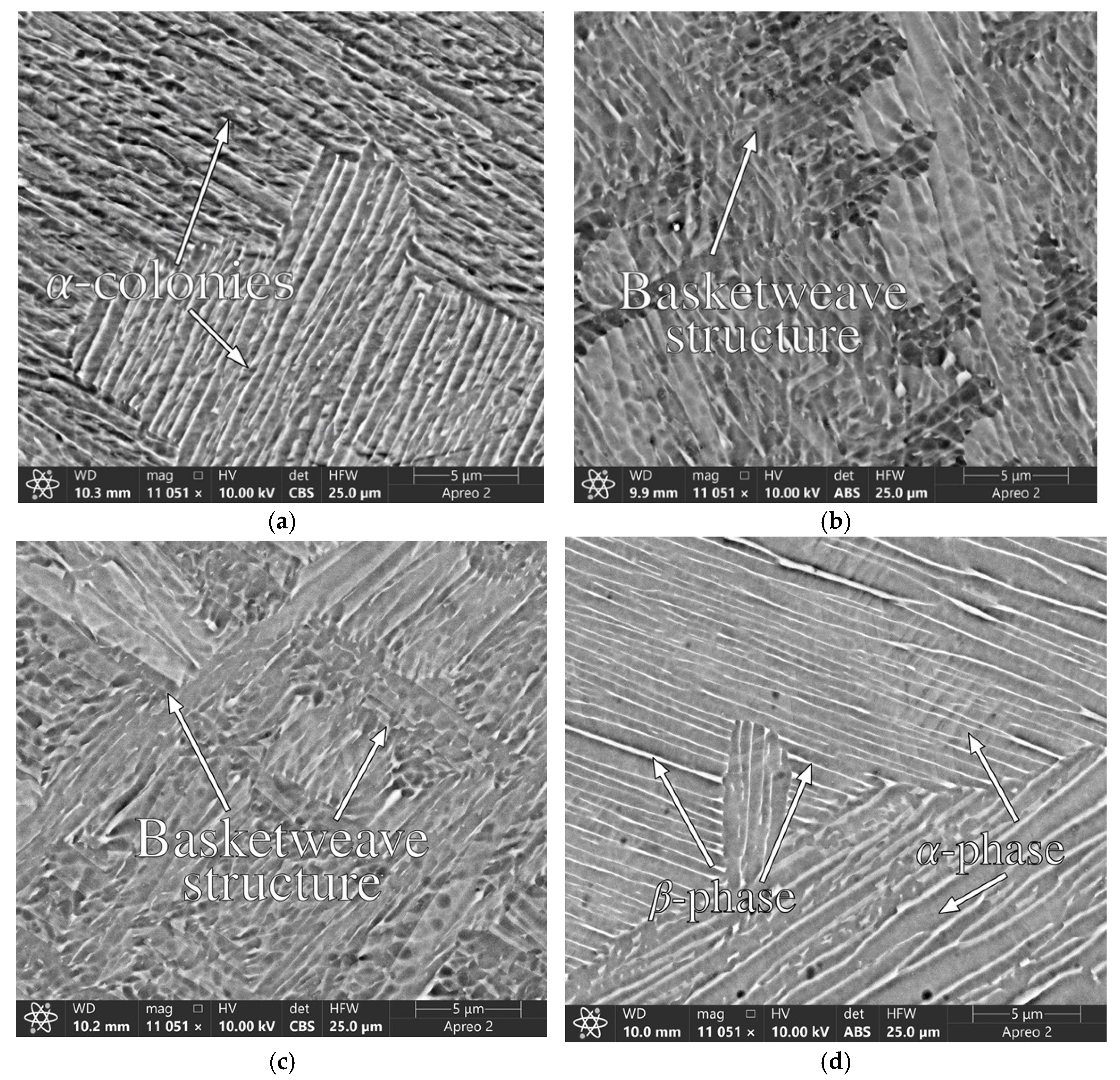
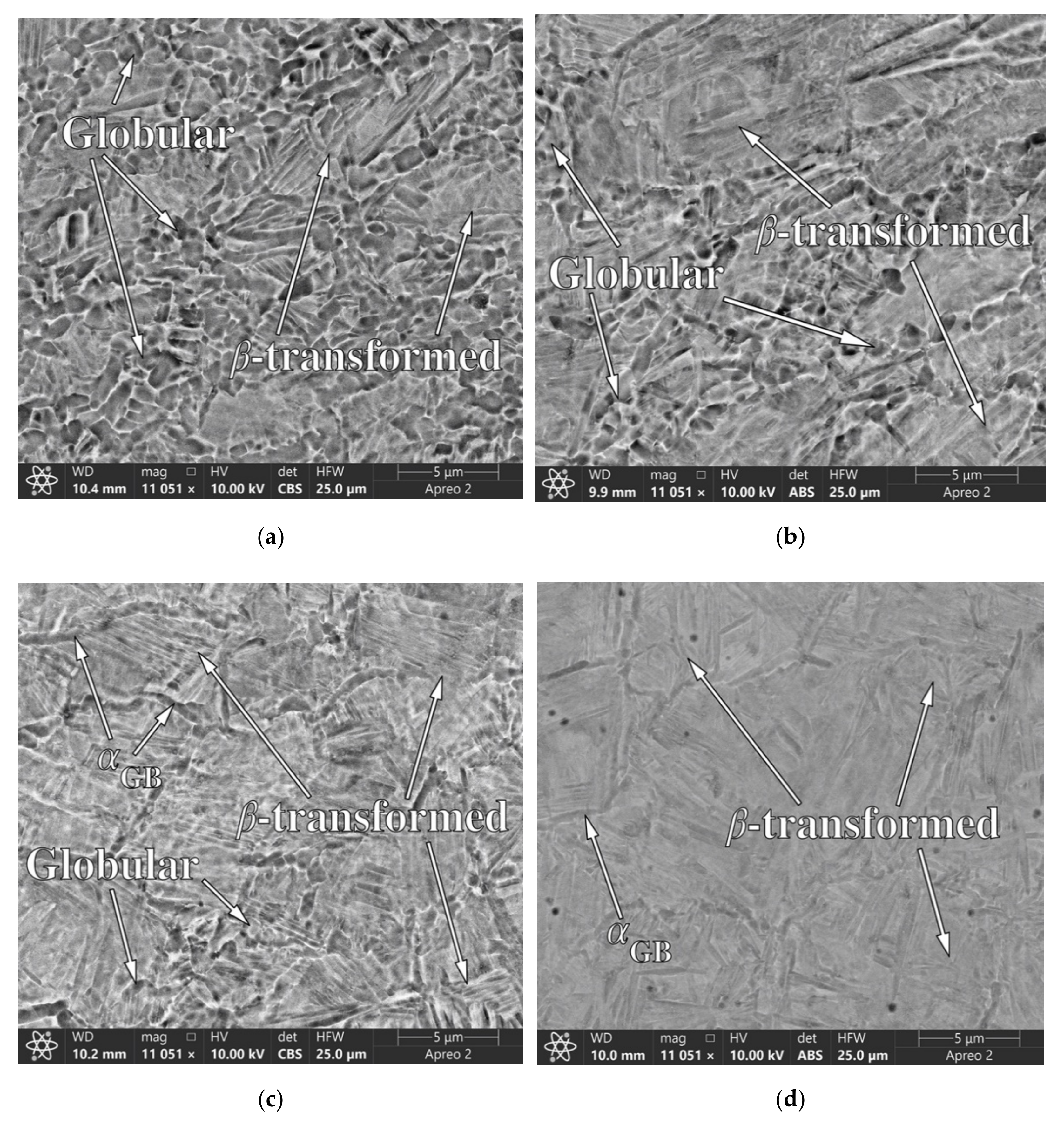
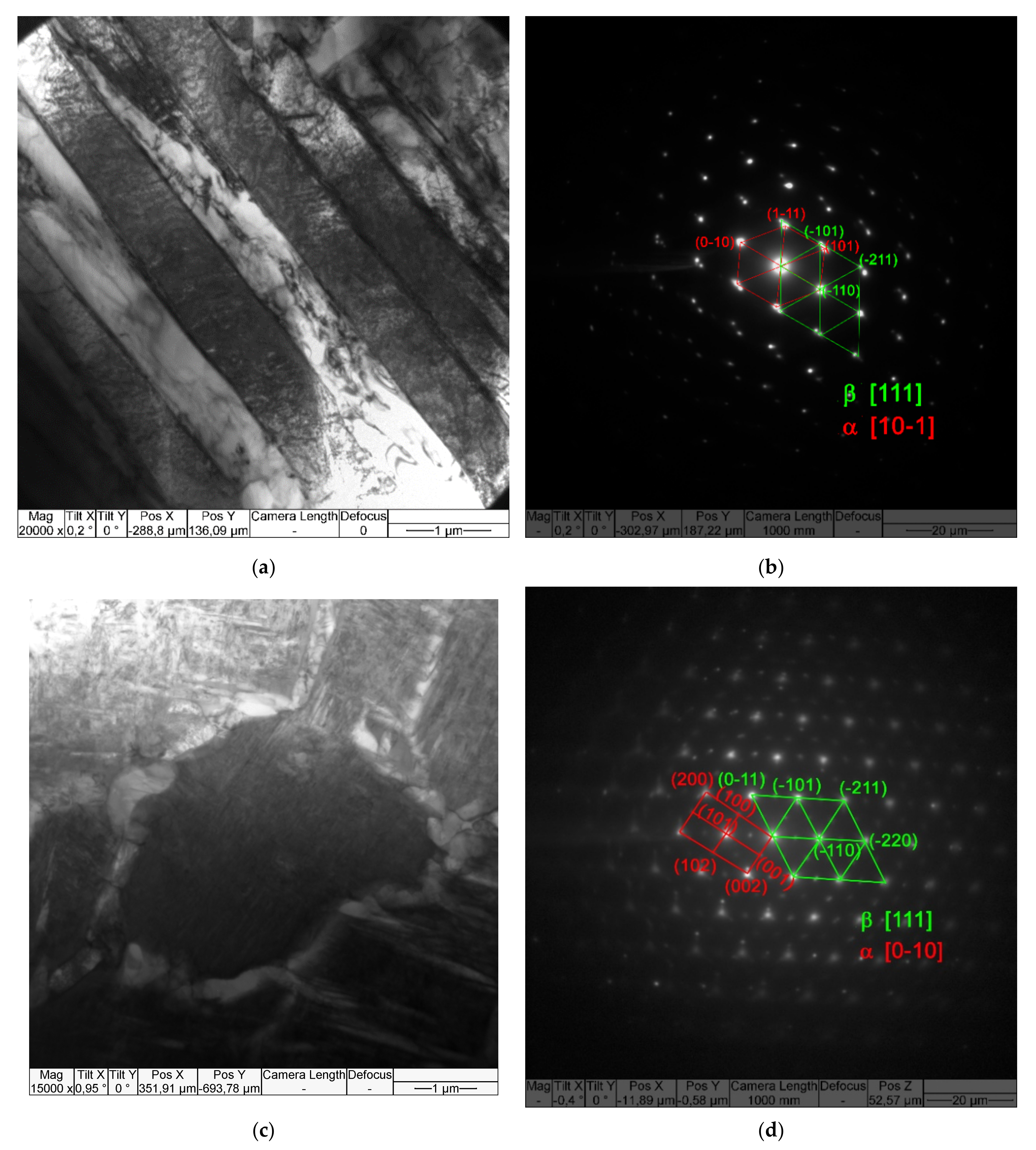
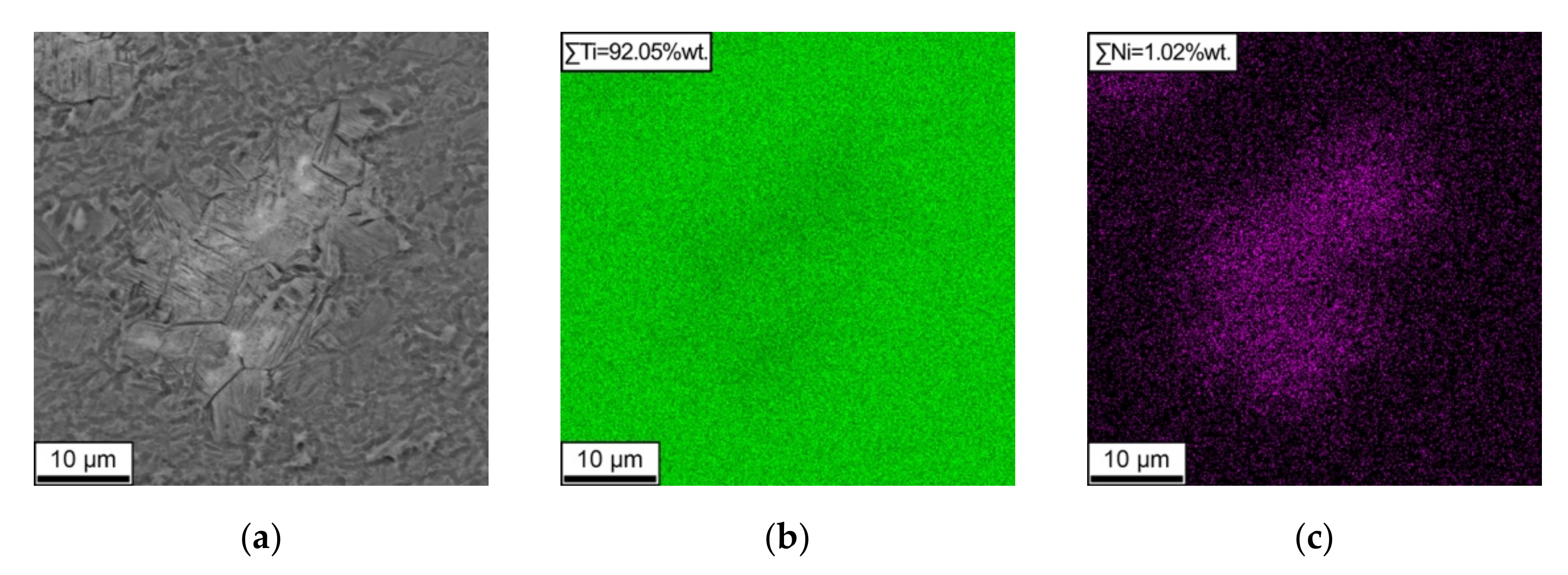
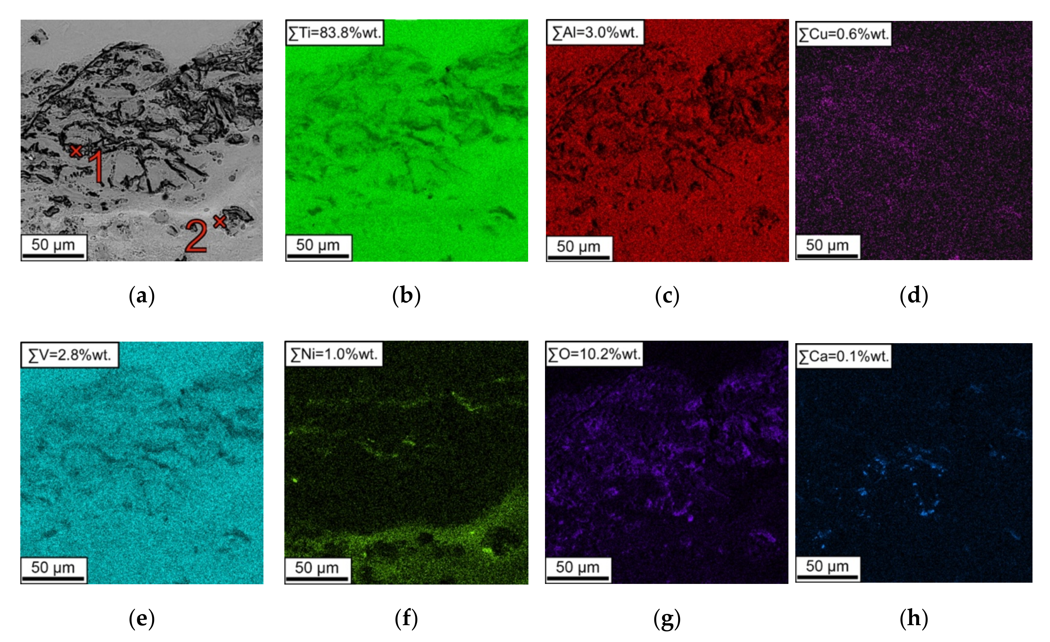
3.2. Microstructure and Chemical Analysis

The sample microstructure was examined using a scanning electron microscope. First, the base metal structure produced by wire-feed electron beam additive manufacturing was studied. As shown in Figure 4, the microstructure inside the columnar grains is represented by microscopic 𝛼-phase plates. Since the type of structure and plate thickness in the additive material can change in the wall growth direction (e.g., from basketweave structure to 𝛼-colonies) [14], the dimensions of the 𝛼-phase plates were measured near the processed zone.
The measurements showed that the average thickness of the 𝛼 plates in the base metal in sample 1 was 0.55 μm, in sample 4, 0.58 μm, and samples 2 and 3, 0.79 and 0.81 μm, respectively. The 𝛼-phase structure is represented mainly by 𝛼-colonies in the samples with the smallest plate thickness, whereas in the samples with the largest plates, the basketweave structure is represented. These differences are due to where the workpieces were cut for processing since the cooling conditions during 3D printing determine the material structure changes [14].
After applying severe plastic deformation by friction stir processing, the structure of the additive material underwent significant changes (Figure 5).
It can be seen from the figure that the structure of the stir zone is different for each of the four samples. In samples 1 and 2, processed along the growth direction of the additive material wall, a typical bimodal microstructure of the stir zone is observed [31]; however, in sample 1, the globular component, i.e., equiaxed and almost equiaxed 𝛼 grains, is predominant. In sample 2, globular structures are also present; however, the 𝛽-transformed structure now predominates [31]. In samples 3 and 4, prepared by processing along the layer deposition direction, the globular structures in the stir zone are practically not observed. As shown from Figure 5c,d, this structure is represented by irregularly shaped primary grains with 𝛼-phase plates inside and 𝛼GB as the grain boundaries. Slight inclusions of the equiaxial 𝛼-phase are also observed near grain boundaries. The size of the 𝛼-phase plates in the stir zone of the samples averages 0.18 microns, which is more than two times smaller than in the base material structure. The average size of the equal 𝛼-phase in the stir zone is about 0.88 μm.
Transmission electron microscopy data confirm the SEM results. Figure 6 shows light-field TEM images of the base metal produced by the additive method and the stir zone material, as well as the obtained microdiffraction. It can be seen that the stir zone 𝛽-transformed structure is an 𝛼+𝛽 with large grain boundary 𝛼-plates.
Chemical analysis of the workpieces showed that aluminum evaporation occurred during wire-feed electron beam additive manufacturing, which resulted in a significant decrease of its concentration. The concentration of vanadium was also lower than the standard concentration. For all workpieces, the average aluminum concentration was 3.58%wt. (grade value from 5.3 to 6.8%wt.), and vanadium was 3.12% (grade value from 3.5 to 5.3%wt.). At the same time, after the processing, the alloy chemical composition in the stir zone remains the same as in the base metal. Furthermore, the energy dispersion analysis made it possible to determine the nature of the inclusions observed in Figure 3 in Section 3.1. Figure 7 and Figure 8 show the distribution maps of chemical elements in the stir zone of the samples.
The figures show two types of inclusions in the material structure. The first type is a product of mutual diffusion of the tool with the workpiece material, as evidenced by the nickel distribution map over the image area (Figure 7c). This type of inclusion is formed because, during the welding process, the tool quickly wears out and mixes into the stir zone [32]. The second type of inclusion is shown in Figure 8. It can be seen that in this area, there is a significant decrease of the concentration of the main components of the Ti-6Al-4V alloy. The oxygen concentration shows that the dark inclusions in Figure 8a are oxides mixed by the tool either from the surface of the workpiece or when the tool makes contact with the substrate. A local EDX-analysis was performed to determine the nature of the formation of such inclusions to identify their components (see Figure 8a and Table 3). It can be seen that the oxide inclusions contain about 38%wt. oxygen, 54%wt. titanium and 1–2%wt. aluminum and vanadium. An important fact is the presence of copper (1.48%wt.) and calcium (1.33%wt.) inclusions, which are not contained in either the tool or the metal being processed. Moreover, one can observe that along with oxide inclusions. There are also inclusions of tool wear products (spectrum 2 in Table 3), which surround the oxide areas in the stir zone and include elements of the tool material, such as nickel (about 27% weight), cobalt (4% weight) and chromium (1.18% weight). The results demonstrate that the stirring of oxides containing foreign inclusions such as calcium and copper into the stir zone are caused by contact between the tool and the substrate. Such an interaction might be caused either by uneven thickness of the additive workpiece or improper tool geometry. This contact results in tool wear and oxides mixing from the substrate surface and the wear products. The following systems can represent the oxide inclusions: Ca-Ti-O, Ca-Al-O, Al-V-O, Cu-V-O and others [33].

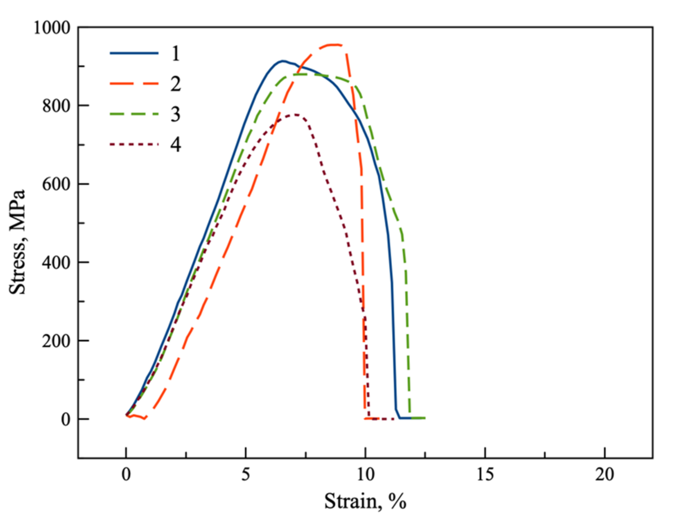
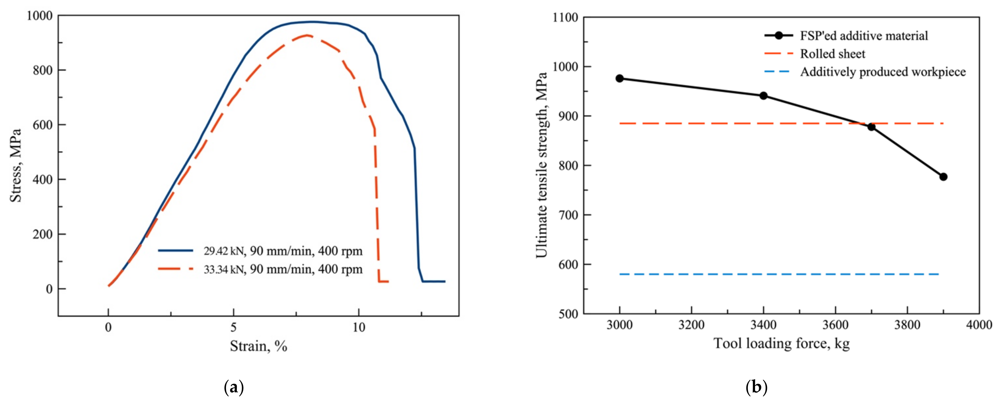
3.3. Mechanical Properties

Static tensile tests were carried out on the base metal test coupons in the direction of wall growth and layer deposition. As a result of the tests, it was found that the additively produced workpieces have significantly lower values of strength characteristics compared to rolled or forged alloy. The material’s ultimate tensile strength in the vertical direction was only 583 MPa, in the horizontal direction it was 578 MPa with relative elongation of 10 and 8%, respectively.
After the friction stir processing passes over the produced workpieces, the mechanical characteristics of the stir zone were obtained for comparison with the base metal properties (Figure 9). As a result, the following values of the stir zone strength were obtained: sample 1 - 914 MPa, sample 2 - 956 MPa, sample 3 - 878 MPa and sample 4 - 777 MPa. The plasticity of samples is about 5–9%.
It is seen that the ultimate tensile strength of material during processing increases dramatically. Strength increment to the additive material is from 34 to 52% in the layer deposition direction and from 57 to 64% in the wall growth direction.

4. Discussion

The research shows that friction stir processing positively affects the strength properties of the additive titanium alloy Ti-6Al-4V. It especially plays an essential role in the case of products fabricated using non-optimal parameters. In this experiment, titanium alloy samples were printed using a beam current constant for each layer to be deposited, while heating–cooling control was performed using pauses between layers (Table 1). It is evident from the results of mechanical tests that this approach is not suitable for 3D printing with titanium alloys, since the ultimate tensile strength of the additive material was only 66% of that of the Ti-6Al-4V alloy sheet [34]. Despite this, thanks to the thermomechanical effect of the friction stir processing method, it was possible to increase the processed material strength significantly. It is possible because, in the FSP process, the structure in the stir zone is significantly changed. Microscopic images in the center of the stir zone indicate that the type of microstructure formed depends on the parameters of the FSP process, in particular on the loading force. At minimum loading force (29.42 kN), a predominantly globular (equiaxed) 𝛼-phase with inclusions of 𝛽-transformed grains is formed in the structure of the stir zone. With the increase in the load from 29.42 to 33.34 kN, the fraction of globular microstructure decreases, and with further increase in the force up to 36.29 and 38.25 kN the structure almost wholly consists of the deformed primary 𝛽-phase grains and 𝛼-phase plates, where the size tends towards nano-scale. In [35], it was shown by the authors that a 𝛽-transformed structure is formed at high welding speeds (1000 rpm and 400 mm/min). However, our results show that it is possible to achieve the desired structure by changing the speed to a much smaller range by controlling the loading force. This point is significant because, according to [36], the strength characteristics of the stir zone decrease with increasing pin rotation speed. The corresponding dependence is also manifested when the loading force is increased since similar structure modification processes occur.
Samples processed in the layer deposition direction with loads of 36.29 and 38.25 kN show tensile strengths 1% and 12% lower than the strength of the rolled sheet, respectively. Additional samples were prepared with axial loads of 29.42 kN and 33.34 kN, feed speed of 90 mm/min and tool rotational speed of 400 rpm to see if the processing direction or purely process parameters affected this. These additional samples were tested similarly in static tensile tests, and the results showed the following strength properties (Figure 10a). For a 39.42 kN load, tensile strength is 976 MPa. For a load of 33.34 kN, tensile strength is 927 MPa. Thus, an increase of 4.7–10.3% compared to the strength of sheet metal and an increase of 60–69% compared to the initial additive manufacturing product was achieved. Figure 9 shows that the produced additional samples provide, in addition to high strength, a sufficient level of the stir zone material ductility, not conceding to the additive workpiece of the Ti-6Al-4V alloy. Moreover, the obtained characteristics are at the same level as the samples produced with similar friction stir processing parameters in the wall growth direction. According to the obtained data, it is evident that the processing direction does not affect the mechanical characteristics of the stir zone metal, and the selection of parameters should be based only on the thickness and chemical composition of the workpiece. Additionally, it is worth noting how changing the loading force affects the mechanical properties. Figure 10a shows that at a load of 29.42 kN, both the strength and ductility are higher than at a 33.34 kN loading force. With a further increase of tool loading force (3, 4 in Figure 8), the material’s ultimate tensile strength continues to decrease. This mechanical behavior is due to the influence of the load on the temperature during processing and the formation of different types of stir zone structures, as discussed earlier. Consequently, for the additive Ti-6Al-4V alloy, the axial load can be selected as the friction stir processing control parameter, determining the material structure and mechanical properties (Figure 10b).

5. Conclusions

The conducted studies of friction stir processing of titanium alloy Ti-6Al-4V workpieces produced via wire-feed electron-beam additive manufacturing have allowed the following conclusions to be drawn:
  • During processing, the stir zone can include stirred FSW-tool wear products as the nickel-based alloy elements and oxides stirred by the tool.
  • Different types of structures can form in the stir zone depending on the tool loading force. As the loading force increases, the structure changes from predominantly globular to almost completely 𝛽-transformed.
  • The strength of the stir zone material depends on the processing parameters. As the axial loading force increases, the strength of the material decreases regardless of the processing direction.
  • The tensile strength of the FSP’ed material increases from 34 to 64% compared to the additive workpiece material. Therefore, friction stir processing can be successfully used to harden additively fabricated Ti-6Al-4V alloy.

Author Contributions

Conceptualization, K.K. and A.C. (Andrey Chumaevskii); methodology, K.K.; validation, A.A.; formal analysis, K.K.; investigation, T.K., E.M. and A.C. (Andrey Cheremnov); resources, A.C. (Andrey Chumaevskii).; data curation, V.K.; writing—original draft preparation, K.K.; writing—review and editing, T.K. and A.C. (Andrey Chumaevskii); visualization, K.K.; supervision, E.K.; project administration, E.K.; funding acquisition, E.K. All authors have read and agreed to the published version of the manuscript.

Funding

The work was performed according to the Government research assignment for ISPMS SB RAS, project FWRW-2021-0012.

Institutional Review Board Statement

Not applicable.

Informed Consent Statement

Not applicable.

Data Availability Statement

Not applicable.

Conflicts of Interest

The authors declare no conflict of interest.

References

  1. Boyer, R.R. Attributes, characteristics, and applications of titanium and its alloys. JOM 2010, 62, 21–24. [Google Scholar] [CrossRef]
  2. Leyens, C.; Peters, M. Titanium and Titanium Alloys: Fundamentals and Applications; John Wiley & Sons: Hoboken, NJ, USA, 2003; ISBN 3527305343. [Google Scholar]
  3. Fujii, H.; Takahashi, K.; Yamashita, Y. Application of Titanium and Its Alloys for Automobile Parts. Nippon. Steel Tech. Rep. 2003, 88, 70–75. [Google Scholar]
  4. Cotton, J.D.; Briggs, R.D.; Boyer, R.R.; Tamirisakandala, S.; Russo, P.; Shchetnikov, N.; Fanning, J.C. State of the Art in Beta Titanium Alloys for Airframe Applications. JOM 2015, 67, 1281–1303. [Google Scholar] [CrossRef] [Green Version]
  5. Peters, M.; Kumpfert, J.; Ward, C.H.; Leyens, C. Titanium Alloys for Aerospace Applications. Adv. Eng. Mater. 2003, 5, 419–427. [Google Scholar] [CrossRef]
  6. Lee, H.S.; Yoon, J.H.; Yoo, J.T. Manufacturing Titanium and Al-Li Alloy Cryogenic Tanks. Key Eng. Mater. 2020, 837, 64–68. [Google Scholar] [CrossRef]
  7. Singh, P.; Pungotra, H.; Kalsi, N.S. On the characteristics of titanium alloys for the aircraft applications. Mater. Today Proc. 2017, 4, 8971–8982. [Google Scholar] [CrossRef]
  8. Taminger, K.M.; Hafley, R.A. Electron beam freeform fabrication for cost effective near-net shape manufacturing. Nato Avt 2006, 139, 11–16. [Google Scholar]
  9. Sciaky.com. EBAM® Drives Innovation for Many Applications and Industries. Available online: https://www.sciaky.com/additive-manufacturing/applications-industries (accessed on 29 November 2021).
  10. Wu, B.; Pan, Z.; Ding, D.; Cuiuri, D.; Li, H.; Xu, J.; Norrish, J. A review of the wire arc additive manufacturing of metals: Properties, defects and quality improvement. J. Manuf. Process. 2018, 35, 127–139. [Google Scholar] [CrossRef]
  11. Fuchs, J.; Schneider, C.; Enzinger, N. Wire-based additive manufacturing using an electron beam as heat source. Weld. World 2018, 62, 267–275. [Google Scholar] [CrossRef] [Green Version]
  12. Pixner, F.; Buzolin, R.; Schönfelder, S.; Theuermann, D.; Warchomicka, F.; Enzinger, N. Contactless temperature measurement in wire-based electron beam additive manufacturing Ti-6Al-4V. Weld. World 2021, 65, 1307–1322. [Google Scholar] [CrossRef]
  13. Xu, J.; Zhu, J.; Fan, J.; Zhou, Q.; Peng, Y.; Guo, S. Microstructure and mechanical properties of Ti–6Al–4V alloy fabricated using electron beam freeform fabrication. Vacuum 2019, 167, 364–373. [Google Scholar] [CrossRef]
  14. Carroll, B.E.; Palmer, T.A.; Beese, A.M. Anisotropic tensile behavior of Ti–6Al–4V components fabricated with directed energy deposition additive manufacturing. Acta Mater. 2015, 87, 309–320. [Google Scholar] [CrossRef]
  15. Teixeira, Ó.; Silva, F.J.G.; Ferreira, L.P.; Atzeni, E. A Review of Heat Treatments on Improving the Quality and Residual Stresses of the Ti–6Al–4V Parts Produced by Additive Manufacturing. Metals 2020, 10, 1006. [Google Scholar] [CrossRef]
  16. Hoefer, K.; Nitsche, A.; Haelsig, A.; Mayr, P. Manufacturing of Titanium Components with 3DPMD. Metals 2019, 9, 562. [Google Scholar] [CrossRef] [Green Version]
  17. McAndrew, A.R.; Rosales, M.A.; Colegrove, P.A.; Hönnige, J.R.; Ho, A.; Fayolle, R.; Eyitayo, K.; Stan, I.; Sukrongpang, P.; Crochemore, A.; et al. Interpass rolling of Ti-6Al-4V wire + arc additively manufactured features for microstructural refinement. Addit. Manuf. 2018, 21, 340–349. [Google Scholar] [CrossRef]
  18. Mishra, R.S.; Ma, Z.Y. Friction stir welding and processing. Mater. Sci. Eng. R Rep. 2005, 50, 1–78. [Google Scholar] [CrossRef]
  19. Kallee, S.W. 5-Industrial applications of friction stir welding. In Friction Stir Welding; Lohwasser, D., Chen, Z., Eds.; Woodhead Publishing Series in Welding and Other Joining Technologies; Woodhead Publishing: Sawston, UK, 2010; pp. 118–163. ISBN 978-1-84569-450-0. [Google Scholar]
  20. Kalashnikov, K.N.; Tarasov, S.Y.; Chumaevskii, A.V.; Fortuna, S.V.; Eliseev, A.A.; Ivanov, A.N. Towards aging in a multipass friction stir–processed АА2024. Int. J. Adv. Manuf. Technol. 2019, 103, 2121–2132. [Google Scholar] [CrossRef]
  21. Wang, W.; Han, P.; Peng, P.; Zhang, T.; Liu, Q.; Yuan, S.-N.; Huang, L.-Y.; Yu, H.-L.; Qiao, K.; Wang, K.-S. Friction Stir Processing of Magnesium Alloys: A Review. Acta Metall. Sin. Engl. Lett. 2020, 33, 43–57. [Google Scholar] [CrossRef] [Green Version]
  22. Liu, H.J.; Zhou, L.; Huang, Y.X.; Liu, Q.W. Study of the Key Issues of Friction Stir Welding of Titanium Alloy. Mater. Sci. Forum 2010, 638–642, 1185–1190. [Google Scholar] [CrossRef]
  23. Aghajani Derazkola, H.; Khodabakhshi, F.; Gerlich, A.P. Friction-forging tubular additive manufacturing (FFTAM): A new route of solid-state layer-upon-layer metal deposition. J. Mater. Res. Technol. 2020, 9, 15273–15285. [Google Scholar] [CrossRef]
  24. Derazkola, H.A.; Khodabakhshi, F.; Gerlich, A.P. Fabrication of a nanostructured high strength steel tube by friction-forging tubular additive manufacturing (FFTAM) technology. J. Manuf. Process. 2020, 58, 724–735. [Google Scholar] [CrossRef]
  25. Derazkola, H.A.; Khodabakhshi, F.; Simchi, A. Evaluation of a polymer-steel laminated sheet composite structure produced by friction stir additive manufacturing (FSAM) technology. Polym. Test. 2020, 90, 106690. [Google Scholar] [CrossRef]
  26. Kalashnikova, T.A.; Chumaevskii, A.V.; Rubtsov, V.E.; Kalashnikov, K.N.; Kolubaev, E.A.; Eliseev, A.A. Structural Heredity of the Aluminum Alloy Obtained by the Additive Method and Modified Under Severe Thermomechanical Action on Its Final Structure and Properties. Russ. Phys. J. 2020, 62, 1565–1572. [Google Scholar] [CrossRef]
  27. Gangwar, K.; Mamidala, R.; Sanders, D.G. Friction Stir Welding of near α and α + β Titanium Alloys: Metallurgical and Mechanical Characterization. Metals 2017, 7, 565. [Google Scholar] [CrossRef] [Green Version]
  28. Tawfik, M.M.; Nemat-Alla, M.M.; Dewidar, M.M. Enhancing the properties of aluminum alloys fabricated using wire + arc additive manufacturing technique-A review. J. Mater. Res. Technol. 2021, 13, 754–768. [Google Scholar] [CrossRef]
  29. Chen, T.; Pang, S.; Tang, Q.; Suo, H.; Gong, S. Evaporation Ripped Metallurgical Pore in Electron Beam Freeform Fabrication of Ti-6-Al-4-V. Mater. Manuf. Process. 2016, 31, 1995–2000. [Google Scholar] [CrossRef]
  30. Agha Amini Fashami, H.; Bani Mostafa Arab, N.; Hoseinpour Gollo, M.; Nami, B. Numerical and experimental investigation of defects formation during friction stir processing on AZ91. SN Appl. Sci. 2021, 3, 108. [Google Scholar] [CrossRef]
  31. Mironov, S.; Sato, Y.S.; Kokawa, H. Friction-stir welding and processing of Ti-6Al-4V titanium alloy: A review. J. Mater. Sci. Technol. 2018, 34, 58–72. [Google Scholar] [CrossRef]
  32. Amirov, A.; Eliseev, A.; Kolubaev, E.; Filippov, A.; Rubtsov, V. Wear of ZhS6U Nickel Superalloy Tool in Friction Stir Processing on Commercially Pure Titanium. Metals 2020, 10, 799. [Google Scholar] [CrossRef]
  33. Sibum, H.; Güther, V.; Roidl, O.; Habashi, F.; Wolf, H.; Siemers, C. Titanium, Titanium Alloys and Titanium Compounds. In Ullmann’s Encyclopedia of Industrial Chemistry; Wiley: Hoboken, NJ, USA, 2017; pp. 1–35. [Google Scholar]
  34. Database of Steel and Alloy (Marochnik). Available online: http://www.splav-kharkov.com/en/e_mat_start.php?name_id=1298 (accessed on 29 November 2021).
  35. Sanders, D.G.; Ramulu, M.; Edwards, P.D.; Cantrell, A. Effects on the Surface Texture, Superplastic Forming, and Fatigue Performance of Titanium 6AL-4V Friction Stir Welds. J. Mater. Eng. Perform. 2010, 19, 503–509. [Google Scholar] [CrossRef] [Green Version]
  36. Zhang, Y.; Sato, Y.S.; Kokawa, H.; Park, S.H.C.; Hirano, S. Microstructural characteristics and mechanical properties of Ti–6Al–4V friction stir welds. Mater. Sci. Eng. A 2008, 485, 448–455. [Google Scholar] [CrossRef]
Figure 1. Vacuum chamber of the wire-feed electron beam additive manufacturing equipment with 3D-printed workpiece (a); the friction stir welding machine (b); and scheme of friction stir processing in the sample growth direction (c). 1—wire-feeder, 2—as-built workpiece, 3—working table, 4—substrate clip, 5—FSW-tool, 6—clamps, 7—FSP’ed workpiece, 8—surface of an additive as-built workpiece with columnar grains, V—tool movement speed, P—tool loading force, ω—tool rotation speed.
Metals 12 00055 g001
Figure 2. Schemes of samples cutting (a,b) and FSW-tool (c): (a) Production of FSP workpieces; (b) Cutting test coupons from FSP area. I, II, II—the stages of obtaining workpieces; 1—stir zone, 2—tool outlet area; 3—test coupons.
Metals 12 00055 g002
Figure 3. Cross sections of FSP’ed samples of additive Ti-6Al-4V alloy workpieces by modes 1 (a), 2 (b), 3 (c) and 4 (d). 1—stir zone; 2—base metal, 3—inclusions of FSW-tool wear product, 4—void, 5—additive manufacturing defects. The dashed lines indicate the boundaries of the stir zone (blue) and the boundaries of the primary β-phase grains in the workpiece material (red).
Metals 12 00055 g003
Figure 4. Base metal microstructure of samples 1 (a), 2 (b), 3 (c) and 4 (d) captured in backscattered electron mode.
Metals 12 00055 g004
Figure 5. Stir zone microstructure of samples 1 (a), 2 (b), 3 (c) and 4 (d) captured in backscattered electron mode.
Metals 12 00055 g005
Figure 6. Light-field TEM images and microdiffraction patterns: (a,b) additive Ti-6Al-4V; (c,d) additive Ti-6Al-4V after FSP.
Metals 12 00055 g006
Figure 7. EDX-mapping of the stir zone area with inclusions in sample 1: (a) BSE-image; (b) titanium and (c) nickel distribution.
Metals 12 00055 g007
Figure 8. EDX-mapping of the stir zone area with inclusions in sample 2: (a) BSE-image; (b) titanium, (c) aluminum, (d) copper, (e) vanadium, (f) nickel, (g) oxygen and (h) calcium distribution.
Metals 12 00055 g008
Figure 9. Stir zone material tensile test diagram.
Metals 12 00055 g009
Figure 10. Stress-strain curves for additional samples, processed in the layer deposition direction (a); dependence of the Ti-6Al-4V stir zone ultimate tensile strength on the tool loading force (b).
Metals 12 00055 g010
Table 1. 3D-printing parameters for Ti-6Al-4V wall.
Accelerating Voltage, kVBeam Current, mATravel Speed, mm/minBeam Sweep ShapeBeam Sweep Frequency, HzPause Between Layers, s
3045400Ring Ø5 mm10005
Table 2. Friction stir processing modes.
NumberProcessing DirectionLoading Force, kNTool Movement Speed, mm/minTool Rotation Speed, rpm
1Wall growth direction 29.4290360
233.3490400
3Layer deposition direction36.2990400
438.2590400
Table 3. EDX-analysis of inclusions in stir zone of sample 4.
SpectrumTiAlVNiCoCrWMoCuCaO
154.321.041.740000.671.091.481.3337.69
259.553.310.7526.684.021.181.10003.31
Publisher’s Note: MDPI stays neutral with regard to jurisdictional claims in published maps and institutional affiliations.

