1. Introduction
The development of new high-strength and temperature-resistant metallic materials is an urgent task faced by specialists working in space, aircraft, and automobile industries. Nowadays, nickel-based, high-temperature strength alloys are widely applied for fabricating gas and steam turbine blades or exhaustive gas heat shields [
1]. However, their working temperatures are less than those of refractory metal aluminides [
2,
3,
4,
5]. Molibdenum aluminides are attracting more and more attention of the researchers since they possess a combination of high melting temperature and thermal stability with high mechanical characteristics [
6,
7,
8]. Their resistance to oxidizing is also very high because of the formation of passivation Al
2O
3 film [
9].
Due to its low solubility in aluminum, molybdenum forms a number of hard intermetallic AlxMoy compounds (IMCs) that might have been used for reinforcing the aluminum alloy matrix if properly dispersed and distributed in it. Such a composite structure can be used for improving both mechanical and functional characteristics of the alloy.
Despite there has always been some constant interest in obtaining and studying the Al
xMo
y IMCs, their mechanical characteristics are still understudied and there are discrepancies in the experimental results reported by different researchers. For instance, Yihan Bian et al. [
10] showed that MoAl
12 not only had a high melting point but also retained its strength under high-temperature loading. It was reported also [
11] that MoAl
12, MoAl
5, MoAl
4, Mo
3Al
8 and Mo
3Al IMCs possess thermodynamic and dynamic stabilities, which are depended on the Mo content so that Mo
3Al
8 is the most stable IMC as compared to other ones, and bulk modulus of Al-Mo alloys tends to grow with the Mo content [
11]. Mingliang Wang et al. [
7] established that the calculated bulk elasticity and shear moduli of MoAl
5 were 115.7 GPa and 95.0 GPa, respectively. Eumann M. et al. [
6] demonstrated that Mo
3Al had a yield stress of 1600 MPa and high brittleness. Rikiya Nino et al. [
8] showed that coarse lamellar Mo
3Al–Mo
3Al
8 served to suppress crack nucleation in Vickers indentation at loads as high as 9.8 N, while fine lamellar structures fractured during indentation at 2.94 N load. Such a result seems to be surprising since common opinion is that the finer the structure the higher is the fracture toughness.
The processes used for synthesizing the Al
xMo
y IMCs mainly are as follows: laser powder-bed fusion [
12], hot dipping of Mo rods into a commercial Al-12 wt.% Si alloy melt [
13], stir casting [
14,
15], reactive hot-pressing [
16], magnetron sputtering [
17], friction stir processing [
18,
19], etc.
Additive manufacturing (AM) is an alternative to traditionally used methods of fabricating materials and articles. Small-scale AM machines equipped with laser, plasma arc, or electron beam energy sources are produced commercially to enable production of machine components directly at place of use from powders or wires. AM has potential for fabricating figurine-shaped components from in-situ formed metal matrix composites, functionally graded or polymetallic materials as depending on the source materials used. Progress achieved in the field of additive manufacturing and materials science allowed using the AM in machine building, aircraft or space applications industries. One of the most important examples is using the AM for fabricating a jet engine collector for Airbus [
20].
Using the AM methods for in-situ preparation of metallic matrix composites or functionally graded materials requires resolving problems with respect to materials compatibility, reactive diffusion zone characteristics, improving as-cast structure characteristics, avoiding porosity, shrinkage pores, etc. Some of the above problems may be resolved with properly selecting the AM method.
Additive manufacturing methods used for making metallic components include wire arc additive manufacturing (WAAM) [
21,
22,
23,
24,
25], selective laser melting (SLM) [
26,
27,
28] and electron beam additive manufacturing (EBAM) [
29,
30,
31,
32]. These methods have their own advantages and disadvantages but the majority of experiments on making aluminum alloy matrix composites were carried out using these three.
For instance, Gasper et al. [
33] used a combined powder/wire feed direct energy deposition for in-situ preparation of titanium aluminides. SLM on AlSi10Mg/SiC allowed obtaining AlSi10Mg/SiC composites [
33] characterized by reduced friction and wear. Intermixing TiC particles with aluminum alloy during the WAAM resulted in grain refining and improved mechanical characteristics of the composites obtained [
34,
35]. Applicability of inoculating particles of oxides, carbides, metallic for improving the microstructure and mechanical characteristics of alloys was discussed in a number of review articles as follows: [
36,
37,
38,
39].
A combination of powder-bed and wire-feed EBAM processes allowed fabricating boron carbide/aluminum bronze composite [
40]. Such a process can also be used for preparation of an Al/Mo composite reinforced by in-situ reactive diffusion formed IMCs. Such an approach was never used earlier in this system and can be of interest from the viewpoint of materials science.
The objective of this work is, therefore, to prepare Al/Mo composite layers using EBAM and study their microstructural and mechanical characteristics depending on the Mo concentration.
2. Materials and Methods
Electron beam deposition was carried out using an aluminum alloy of ⌀1.2 mm wire of composition, wt.%: 3.8 ± 0.4 Mg, 0.2 ± 0.01 Fe, 0.1 ± 0.02 Mn, 0.1 ± 0.01 Ti, 0.02 ± 0.003 Cu, 0.01 ± 0.002 Zn, and Al—balance, that corresponded to that of AA5154. A molybdenum powder bed was formed by spreading 98.7% purity Mo particles on the as-deposited AA51514. The Mo powder was composed of deagglomerated ~2 µm particles and 3–12 μm agglomerates.
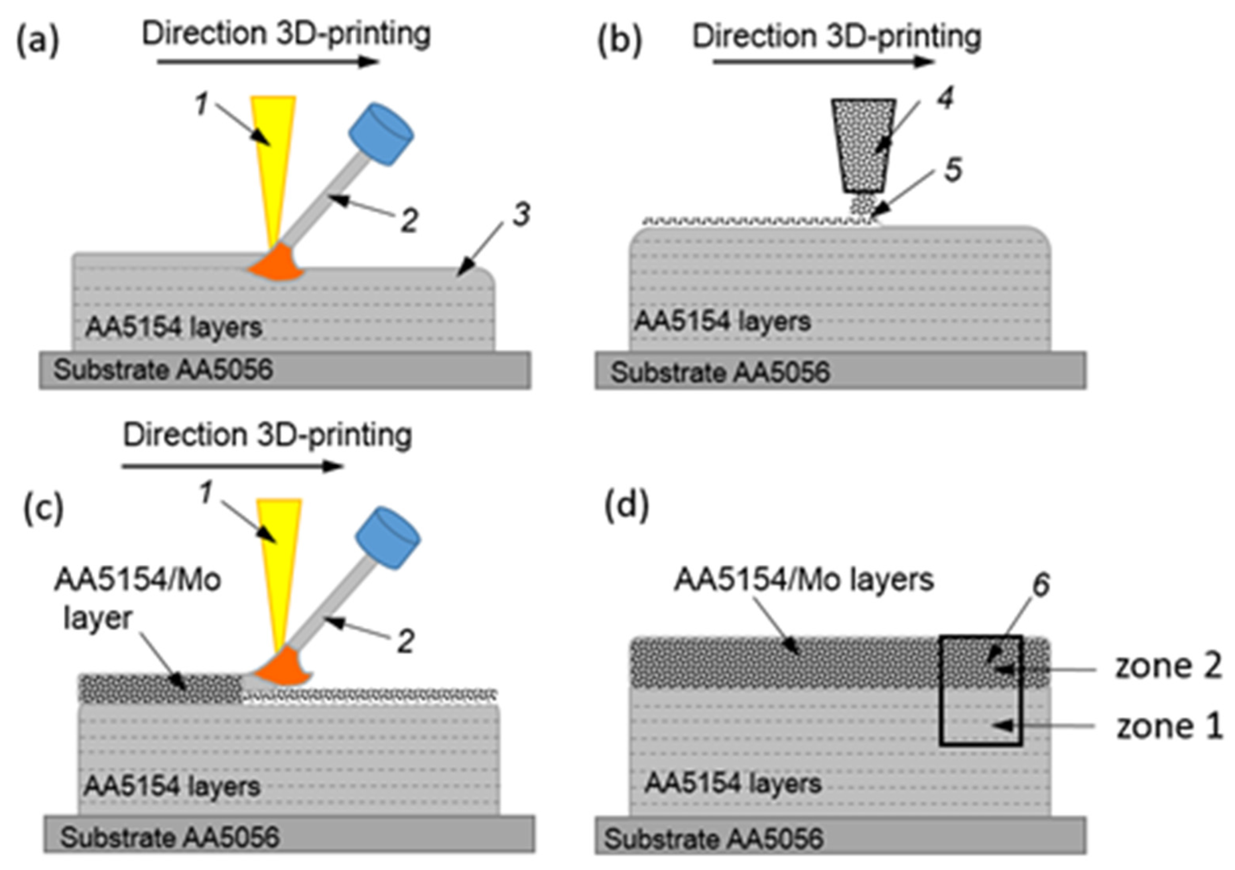
EBAM parameters used for deposition of first eight AA5154 layers on a AA5154 substrate (
Figure 1a, pos. 3), are shown in
Table 1. These parameters were the same as those used earlier for growing the quality and defectless AA5356 walls [
41].
On depositing these 8 layers, a powder feeder (
Figure 1b, pos. 4) was used to form a molybdenum powder bed of the total weight of 0.3 g on the as-deposited metal. The next step was remelting the powder bed with simultaneous deposition of AA5154 from the wire. Such a cycle was then repeated twice so that the total number of the remelted powder beds was 3. Similar procedures were carried out for powder beds amounting to 0.6, 0.9, and 1.2 g/per a layer. The resulting walls had the dimensions as follows: 60 × 20 × 30 mm
3.
The distribution of Mo in the as-deposited samples was studied using an X-ray tomograph Cheetah X-ray Inspection System EVO (YXLON International GmbH, Hamburg, Cermany). Metallographic examination of samples was carried out using optical microscope Altami Met 1S (LCC, Altami, St. Petersburg, Russia) and scanning electron microscope Tescan MIRA 3 LMU (TESCAN ORSAY HOLDING, Brno, Czech Republic), equipped with Oxford Instruments Ultim Max 40 EDS detector (Oxford Instruments, High Wycombe, UK). TEM examinations were performed using TEM instrument JEOL-2100 (JEOL Ltd., Akishima, Japan) on foils thinned by a focused ion beam.
X-ray diffraction (XRD) phase analysis was carried out by means of an X-ray diffractometer DRON-7 (Innovation Center “Burevestnik”, St. Petersburg, Russia) using CoKα radiation at 0.05° increments and an exposure time of 25 s/step that allowed detecting phases such as Al and Mo as well as their intermetallic compounds (IMCs). Grazing-incidence X-ray diffraction (GIAXD) at beam incidence angle of 10° was applied for studying phases formed in a thin subsurface layer by friction against the steel disk. The XRD peak identification and treatment was performed using Crystal Impact software “Match!” (version 3.9, Crystal Impact, Bonn, Germany). The phase contents were obtained from the XRD data according to Equation (1), where
Vphase is the phase percentage,
Iphase is the phase’s integral phase peak intensity –, and
Iphase is the integral intensity of any other reflection.
Microhardness of the phases was measured using a Duramin5 (Struers A/S, Ballerup, Denmark) machine. A tensile test machine UTS-110M-100 (Testsystems, Ivanovo, Russia) and tribometer TRIBOtechnic (Tribotechnic, Clichy, France) were used for determining the sample strength and tribological behavior, respectively.
Pin-on-disk sliding was applied for measuring the friction and wear characteristics of samples. Samples in the form of 3 × 3 × 10 mm3 pins were cut off the AA5154/Mo zone, while Ø35 mm, 5 mm thickness counterbody disks were machined from 40 × 13 quenched steel. Rotation rate, normal load and sliding path length were 94 RPM, 15 N and 5600 m, respectively.
4. Discussion
Molybdenum has low diffusion factor, rather low solubility in aluminum and is capable of forming a row of hard Al
xMo
y IMCs. The results of this work allowed showing that changing the amount of Mo charged into the aluminum matrix at a step as low as 0.3 g resulted in a notable increase in the volume fraction of IMCs in the aluminum alloy matrix. Both Mo-rich and Al-rich IMCs were formed depending on the distribution of the Mo powder particles in the melted pool. The latter ones, such as Al
12Mo and Al
18Mg
3Mo
2, were detected using XRD, EDS and partially TEM. Let us note that many IMCs were pulled out of the matrix during sample preparation procedures and therefore had never been analyzed. The morphology of Al
12Mo IMCs changed depending on the concentration differences and solidification front atomic morphology [
44] that is determined according to the expression as follows:
where α is the fusion entropy, Δ
Sf is the specific fusion entropy per mole,
R is the universal gas constant. The unfaceted crystals grow at α < 2, while values higher than α > 2 facilitate the formation of crystalline faces [
44].
The IMC phase formation is determined by Gibbs energy change during the diffusion reaction between Al and Mo as follows: (
) [
45]:
where
is the change in enthalpy;
T is the reaction temperature;
is the change in entropy that can be neglected in this solid state case to allow rewriting Equation (3) as follows:
≈
.
For the Al-Mo system, the probability of an IMC formation by diffusion reaction can be explained using several adopted models [
45,
46]. Pretorius R. et al. [
45] proposed a model for determining the effective heat of formation (
) on the binary metal/aluminum phase interface:
where
is the effective heat of formation of the
i-phase,
Ce is the effective concentration of the limiting element at the interface, and
Cc is the concentration of the limiting element in the compound. Assuming that
≈
, the effective Gibbs energy change in the case of forming the
i-phase in the Al/Mo layer may be determined as follows:
Table 7 contains the effective Gibbs free energy changes calculated for all Al/Mo phases.
It follows from
Table 7 that all Al
xMo
y phases have negative values of the Gibbs free energy changes and therefore can be formed in our experimental conditions. The minimal values belong to the Al-rich ones detected in the experiment. Al-Mo solid solutions may also form in the Al-rich areas
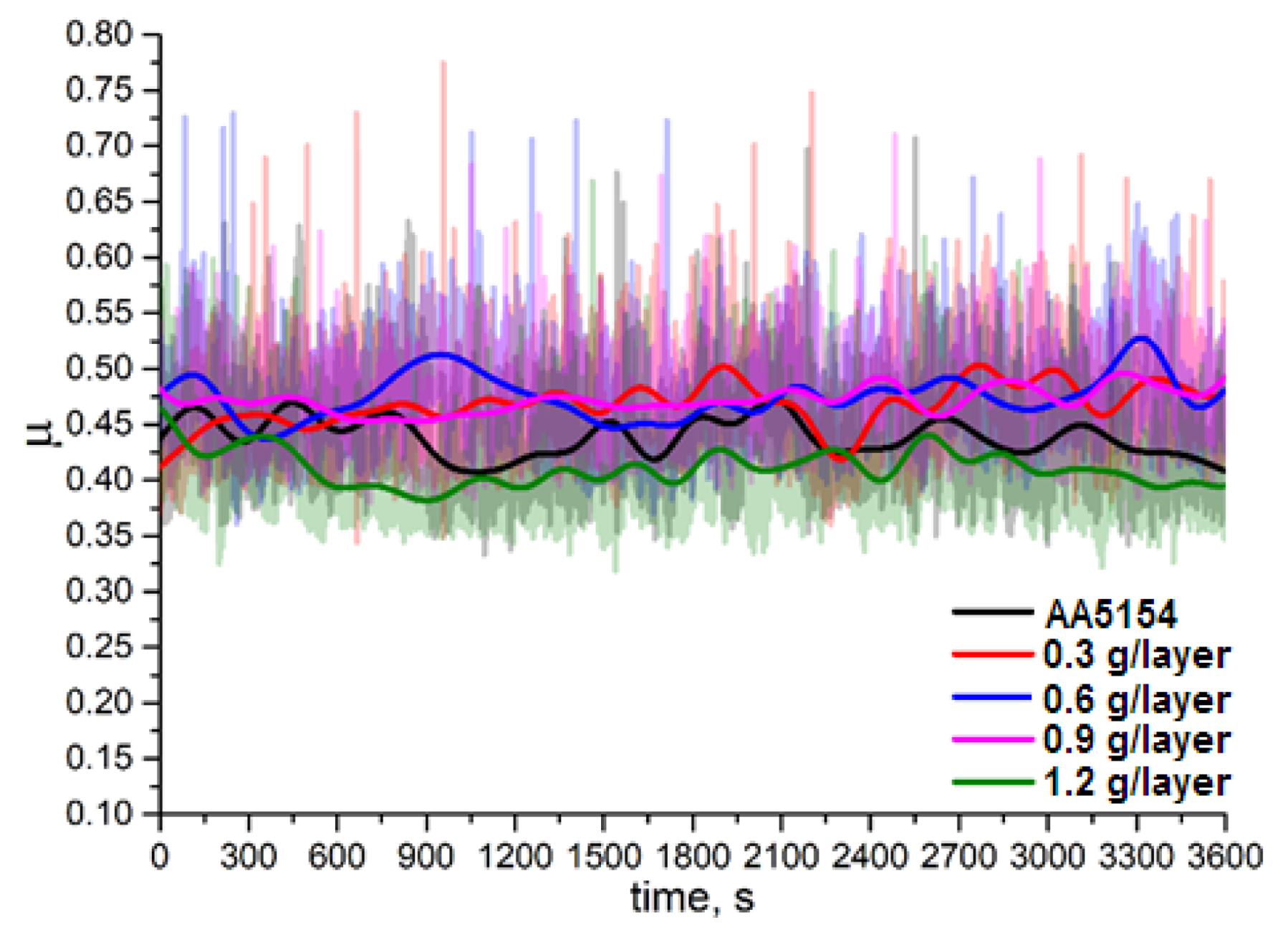
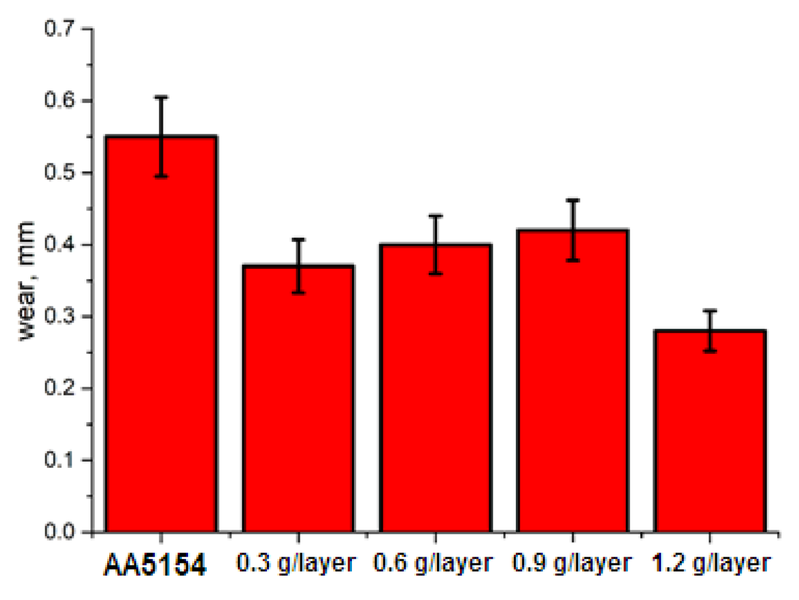
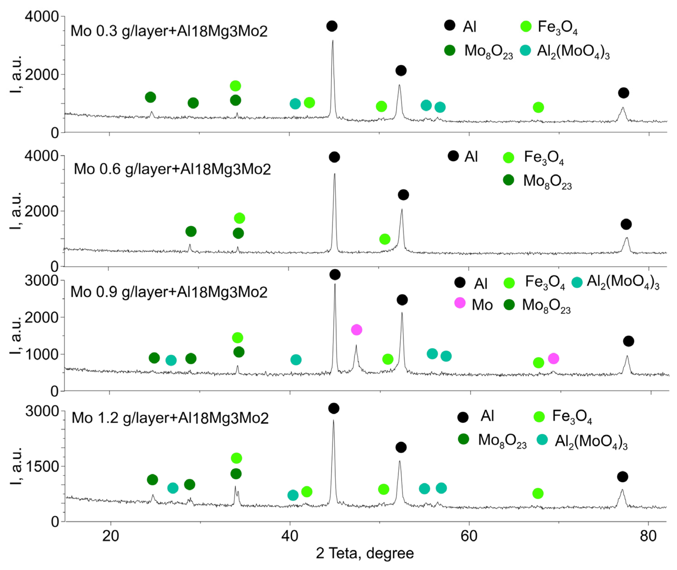
Inhomogeneous distribution of Mo particles and brittle Al/Mo IMCs, as well as the presence of defects such as voids, resulted in non-uniform distribution of the microhardness numbers. The friction and wear behavior of samples showed reduced friction and wear for all the AA5154/Mo samples as compared to that of AA5154. The IMCs allowed increasing the worn subsurface hardness and generating mechanically mixed layers (MML) consisting of Fe
3O
4, Mo
8O
23 and Al
2(MoO
4)
3 oxides, which formed due to tribooxidation of Al
xMo
y IMCs and adhesive transfer of iron from the steel counterbody. These oxides may be related to easy shear compounds that provide a lubrication effect and improve the tribological characteristics of composites [
47]. It is also known that [
48] introducing Mo into ceramic coatings served not only for their enhanced hardness and wear resistance, but also reduced friction due to the formation of MoO
3 on the worn surfaces.
However, there was another factor that served for some minor increase in wear for samples containing from 0.3 to 0.9 g/layer of Mo. This factor was the bearing ability of the MML depending on the number of brittle IMCs in the subsurface of the samples, which were pulled out and abraded the worn surface. However, this did not occur with the 1.2 g/layer sample where the maximal amount of self-lubrication oxides was formed to reduce the abrasion intensity.
Author Contributions
Conceptualization, A.Z. and S.T.; Data curation, A.Z. and A.C.; Formal analysis, A.Z., A.C., E.M., D.G. and N.S. (Nickolai Savchenko); Funding acquisition, A.Z.; Investigation, A.Z., A.C., A.V., N.S. (Nickolay Shamarin), E.M., D.G. and N.S. (Nickolai Savchenko); Methodology, A.Z., A.V. and S.T.; Resources, A.Z.; Software, N.S. (Nickolay Shamarin), A.P. and E.K. (Evgeny Knyazhev); Supervision, E.K. (Evgeny Kolubaev); Validation, A.P. and E.K. (Evgeny Knyazhev); Visualization, A.V.; Writing—original draft, A.Z. and S.T.; Writing—review & editing, A.Z., E.K. (Evgeny Kolubaev) and S.T. All authors have read and agreed to the published version of the manuscript.
Funding
This research was funded by the Russian Federation Government under research assignment for ISPMS SB RAS, project no. FWRW-2021-0012.
Institutional Review Board Statement
Not applicable.
Informed Consent Statement
Not applicable.
Data Availability Statement
Data sharing is not applicable to this article.
Conflicts of Interest
The authors declare no conflict of interest.
References
- Yener, T. Low temperature aluminising of Fe-Cr-Ni super alloy by pack cementation. Vacuum 2019, 162, 114–120. [Google Scholar] [CrossRef]
- Ding, Y.; You, G.; Wen, H.; Li, P.; Tong, X.; Zhou, Y. Microstructure and mechanical properties of inertia friction welded joints between alloy steel 42CrMo and cast Ni-based superalloy K418. J. Alloys Compd. 2019, 803, 176–184. [Google Scholar] [CrossRef]
- Wang, C.; Wu, Y.; Guo, Y.; Guo, J.; Zhou, L. Precipitation behavior of sigma phase and its influence on mechanical properties of a Ni-Fe based alloy. J. Alloys Compd. 2019, 784, 266–275. [Google Scholar] [CrossRef]
- Huang, Y.; Liu, Y.; Li, C.; Ma, Z.; Yu, L.; Li, H. Microstructure evolution and phase transformations in Ti-22Al-25Nb alloys tailored by super-transus solution treatment. Vacuum 2019, 161, 209–219. [Google Scholar] [CrossRef]
- Pan, Y.; Wen, M. Ab-initio calculations of mechanical and thermodynamic properties of TM (transition metal: 3d and 4d)-doped Pt3Al. Vacuum 2018, 156, 419–426. [Google Scholar] [CrossRef]
- Eumann, M.; Sauthoff, G.; Palm, M. Re-evaluation of phase equilibria in the Al–Mo system. Int. J. Mater. Res. 2006, 97, 1502–1511. [Google Scholar] [CrossRef]
- Wang, M.; Chen, Z.; Xia, C.; Wu, Y.; Chen, D. Theoretical study of elastic and electronic properties of Al5Mo and Al5W intermetallics under pressure. Mater. Chem. Phys. 2017, 197, 145–153. [Google Scholar] [CrossRef]
- Nino, R.; Miura, S.; Mohri, T. The behavior of cracking in Mo3Al–Mo3Al8 two-phase intermetallics with lamellar structures. Intermetallics 2001, 9, 113–118. [Google Scholar] [CrossRef]
- Kiryukhantsev-Korneev, P.; Iatsyuk, I.; Shvindina, N.; Levashov, E.; Shtansky, D. Comparative investigation of structure, mechanical properties, and oxidation resistance of Mo-Si-B and Mo-Al-Si-B coatings. Corros. Sci. 2017, 123, 319–327. [Google Scholar] [CrossRef]
- Bian, Y.; Gao, T.; Li, Z.; Sun, Q.; Ma, X.; Liu, X. In-situ synthesis of an Al composite reinforced with multi–scale Al12Mo, (Al, Zr, Si) and Al2O3 particles through a multi–stage reaction. Mater. Sci. Eng. A 2019, 762, 138069. [Google Scholar] [CrossRef]
- Pan, Y.; Pu, D.; Liu, G. Influence of Mo concentration on the structure, mechanical and thermodynamic properties of Mo–Al compounds from first-principles calculations. Vacuum 2020, 175, 109291. [Google Scholar] [CrossRef]
- Minasyan, T.; Ivanov, R.; Toyserkani, E.; Hussainova, I. Laser powder-bed fusion of Mo(Si,Al)2—Based composite for elevated temperature applications. J. Alloys Compd. 2021, 884, 161034. [Google Scholar] [CrossRef]
- Sharifitabar, M.; Sadeq, F.O.; Afarani, M.S. Synthesis and kinetic study of Mo(Si,Al)2 coatings on the surface of molybdenum through hot dipping into a commercial Al-12 wt.%Si alloy melt. Surf. Interfaces 2021, 24, 101044. [Google Scholar] [CrossRef]
- Kumar, J.; Singh, D.; Kalsi, N.S.; Sharma, S.; Mia, M.; Singh, J.; Rahman, M.A.; Khan, A.M.; Rao, K.V. Investigation on the mechanical, tribological, morphological and machinability behavior of stir-casted Al/SiC/Mo reinforced MMCs. J. Mater. Res. Technol. 2021, 12, 930–946. [Google Scholar] [CrossRef]
- Pan, S.; Guan, Z.; Yao, G.; Yuan, J.; Li, X. Mo-enhanced chemical stability of TiC nanoparticles in molten Al. J. Alloys Compd. 2021, 856, 158169. [Google Scholar] [CrossRef]
- Richardson, P.J.; Keast, V.J.; Cuskelly, D.T.; Kisi, E.H. Theoretical and experimental investigation of the W-Al-B and Mo-Al-B systems to approach bulk WAlB synthesis. J. Eur. Ceram. Soc. 2021, 41, 1859–1868. [Google Scholar] [CrossRef]
- Cordill, M.; Kreiml, P.; Putz, B.; Mitterer, C.; Thiaudière, D.; Mocuta, C.; Renault, P.-O.; Faurie, D. Role of layer order on the equi-biaxial behavior of Al/Mo bilayers. Scr. Mater. 2021, 194, 113656. [Google Scholar] [CrossRef]
- Lee, I.; Kao, P.; Chang, C.; Ho, N. Formation of Al–Mo intermetallic particle-strengthened aluminum alloys by friction stir processing. Intermetallics 2013, 35, 9–14. [Google Scholar] [CrossRef]
- Mahesh, V.P.; Alphonsa, J.; Arora, A. Electrochemical Behavior of Aluminum-Molybdenum Surface Composites Developed by Friction Stir Processing. J. Mater. Eng. Perform. 2021, 30, 8663–8676. [Google Scholar] [CrossRef]
- Khorasani, M.; Ghasemi, A.; Rolfe, B.; Gibson, I. Additive manufacturing a powerful tool for the aerospace industry. Rapid Prototyp. J. 2021. ahead of print. [Google Scholar] [CrossRef]
- Köhler, M.; Fiebig, S.; Hensel, J.; Dilger, K. Wire and Arc Additive Manufacturing of Aluminum Components. Metals 2019, 9, 608. [Google Scholar] [CrossRef] [Green Version]
- Huang, W.; Chen, S.; Xiao, J.; Jiang, X.; Jia, Y. Laser wire-feed metal additive manufacturing of the Al alloy. Opt. Laser Technol. 2021, 134, 106627. [Google Scholar] [CrossRef]
- Klein, T.; Schnall, M.; Gomes, B.; Warczok, P.; Fleischhacker, D.; Morais, P.J. Wire-arc additive manufacturing of a novel high-performance Al-Zn-Mg-Cu alloy: Processing, characterization and feasibility demonstration. Addit. Manuf. 2021, 37, 101663. [Google Scholar] [CrossRef]
- Tang, S.; Wang, G.; Song, H.; Li, R.; Zhang, H. A novel method of bead modeling and control for wire and arc additive manufacturing. Rapid Prototyp. J. 2021, 27, 311–320. [Google Scholar] [CrossRef]
- Kulkarni, J.D.; Goka, S.B.; Parchuri, P.K.; Yamamoto, H.; Ito, K.; Simhambhatla, S. Microstructure evolution along build direction for thin-wall components fabricated with wire-direct energy deposition. Rapid Prototyp. J. 2021, 27. [Google Scholar] [CrossRef]
- Yang, Y.; Geng, K.; Li, S.; Bermingham, M.; Misra, R. Highly ductile hypereutectic Al-Si alloys fabricated by selective laser melting. J. Mater. Sci. Technol. 2021, 110, 84–95. [Google Scholar] [CrossRef]
- Sun, S.; Liu, P.; Hu, J.; Hong, C.; Qiao, X.; Liu, S.; Zhang, R.; Wu, C. Effect of solid solution plus double aging on microstructural characterization of 7075 Al alloys fabricated by selective laser melting (SLM). Opt. Laser Technol. 2019, 114, 158–163. [Google Scholar] [CrossRef]
- Ma, R.-L.; Peng, C.-Q.; Cai, Z.-Y.; Wang, R.-C.; Zhou, Z.-H.; Li, X.-G.; Cao, X.-Y. Finite element analysis of temperature and stress fields during selective laser melting process of Al–Mg–Sc–Zr alloy. Trans. Nonferrous Met. Soc. China 2021, 31, 2922–2938. [Google Scholar] [CrossRef]
- Utyaganova, V.; Filippov, A.; Tarasov, S.; Shamarin, N.; Gurianov, D.; Vorontsov, A.; Chumaevskii, A.; Fortuna, S.; Savchenko, N.; Rubtsov, V.; et al. Characterization of AA7075/AA5356 gradient transition zone in an electron beam wire-feed additive manufactured sample. Mater. Charact. 2021, 172, 110867. [Google Scholar] [CrossRef]
- Domack, M.S.; Taminger, K.M.; Begley, M. Metallurgical Mechanisms Controlling Mechanical Properties of Aluminium Alloy 2219 Produced by Electron Beam Freeform Fabrication. Mater. Sci. Forum 2006, 519–521, 1291–1296. [Google Scholar] [CrossRef]
- Taminger, K.M.; Hafley, R.A.; Domack, M.S. Evolution and Control of 2219 Aluminium Microstructural Features through Electron Beam Freeform Fabrication. Mater. Sci. Forum 2006, 519–521, 1297–1302. [Google Scholar] [CrossRef]
- Brice, C.A.; Dennis, N. Cooling Rate Determination in Additively Manufactured Aluminum Alloy 2219. Met. Mater. Trans. A 2015, 46, 2304–2308. [Google Scholar] [CrossRef]
- Gasper, A.; Catchpole-Smith, S.; Clare, A. In-situ synthesis of titanium aluminides by direct metal deposition. J. Mater. Process. Technol. 2017, 239, 230–239. [Google Scholar] [CrossRef]
- Langelandsvik, G.; Eriksson, M.; Akselsen, O.M.; Roven, H.J. Wire arc additive manufacturing of AA5183 with TiC nanoparticles. Int. J. Adv. Manuf. Technol. 2021, 1–12. [Google Scholar] [CrossRef]
- Jin, P.; Liu, Y.; Li, F.; Sun, Q. Realization of synergistic enhancement for fracture strength and ductility by adding TiC particles in wire and arc additive manufacturing 2219 aluminium alloy. Compos. Part B Eng. 2021, 219, 108921. [Google Scholar] [CrossRef]
- Behera, M.P.; Dougherty, T.; Singamneni, S. Conventional and Additive Manufacturing with Metal Matrix Composites: A Perspective. Procedia Manuf. 2019, 30, 159–166. [Google Scholar] [CrossRef]
- Mostafaei, A.; Heidarzadeh, A.; Brabazon, D. Production of Metal Matrix Composites Via Additive Manufacturing. In Encyclopedia of Materials: Composites; Elsevier BV: Amsterdam, The Netherlands, 2020; pp. 605–614. [Google Scholar]
- Seetharaman, S.; Gupta, M. Additive Manufacturing of Metal Matrix Composites. In Encyclopedia of Materials: Composites; Elsevier BV: Amsterdam, The Netherlands, 2021; pp. 209–229. [Google Scholar]
- Parsons, E.M.; Shaik, S.Z. Additive manufacturing of aluminum metal matrix composites: Mechanical alloying of composite powders and single track consolidation with laser powder bed fusion. Addit. Manuf. 2021, 50, 102450. [Google Scholar] [CrossRef]
- Filippov, A.; Khoroshko, E.; Shamarin, N.; Savchenko, N.; Moskvichev, E.; Utyaganova, V.; Kolubaev, E.; Smolin, A.; Tarasov, S. Characterization of gradient CuAl–B4C composites additively manufactured using a combination of wire-feed and powder-bed electron beam deposition methods. J. Alloys Compd. 2021, 859, 157824. [Google Scholar] [CrossRef]
- Utyaganova, V.R.; Filippov, A.V.; Shamarin, N.N.; Vorontsov, A.V.; Savchenko, N.L.; Fortuna, S.V.; Gurianov, D.A.; Chumaevskii, A.V.; Rubtsov, V.E.; Tarasov, S.Y. Controlling the porosity using exponential decay heat input regimes during electron beam wire-feed additive manufacturing of Al-Mg alloy. Int. J. Adv. Manuf. Technol. 2020, 108, 2823–2838. [Google Scholar] [CrossRef]
- Schuster, J.C. Materials Science International Team, MSIT® The Assessed Phase Diagram of the Al-Mo System: Datasheet from MSI Eureka in Springer Materials. Available online: https://0-materials-springer-com.brum.beds.ac.uk/msi/phase-diagram/docs/sm_msi_r_20_012123_01_full_LnkDia0 (accessed on 27 November 2021).
- Wu, Q.; Yang, C.; Xue, F.; Sun, Y. Effect of Mo addition on the microstructure and wear resistance of in situ TiC/Al composite. Mater. Des. 2011, 32, 4999–5003. [Google Scholar] [CrossRef]
- Almeida, A.; Carvalho, F.; Carvalho, P.; Vilar, R. Laser developed Al–Mo surface alloys: Microstructure, mechanical and wear behaviour. Surf. Coat. Technol. 2006, 200, 4782–4790. [Google Scholar] [CrossRef]
- Pretorius, R.; Vredenberg, A.M.; Saris, F.W.; De Reus, R. Prediction of phase formation sequence and phase stability in binary metal-aluminum thin-film systems using the effective heat of formation rule. J. Appl. Phys. 1991, 70, 3636–3646. [Google Scholar] [CrossRef]
- Saunders, N.; Thermotech Ltd. The Al-Mo system (aluminum-molybdenum). J. Phase Equilibria Diffus. 1997, 18, 370–378. [Google Scholar] [CrossRef]
- Voevodin, A.; Muratore, C.; Aouadi, S. Hard coatings with high temperature adaptive lubrication and contact thermal management: Review. Surf. Coat. Technol. 2014, 257, 247–265. [Google Scholar] [CrossRef]
- Grigoriev, S.; Vereschaka, A.; Milovich, F.; Sitnikov, N.; Andreev, N.; Bublikov, J.; Kutina, N. Investigation of the properties of the Cr,Mo-(Cr,Mo,Zr,Nb)N-(Cr,Mo,Zr,Nb,Al)N multilayer composite multicomponent coating with nanostructured wear-resistant layer. Wear 2020, 468–469, 203597. [Google Scholar] [CrossRef]
Figure 1.
EBAM process stages such as electron beam deposition of AA5154 layers (a) spreading a Mo powder-bed (b) remelting the Mo powder-bed with deposition of AA5154 (c) as-built AA5154/Mo composite zones (d). 1—electron beam, 2—AA5154 filament, 3—AA5154 layers, 4—powder feeder, 5—Mo powder, 6—samples for SEM and TEM.
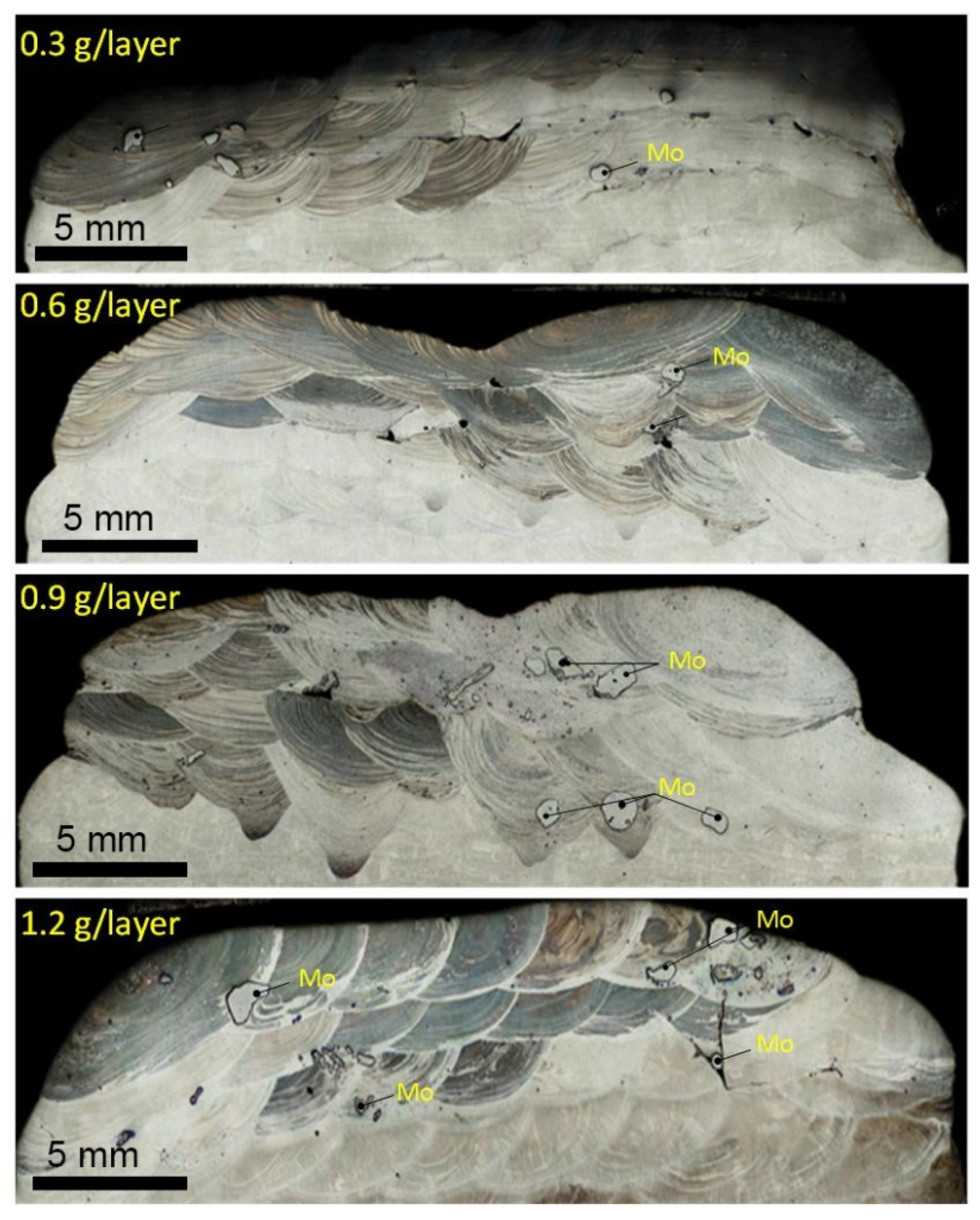
Figure 2.
Optical cross section images of AA5154/Mo track zones.
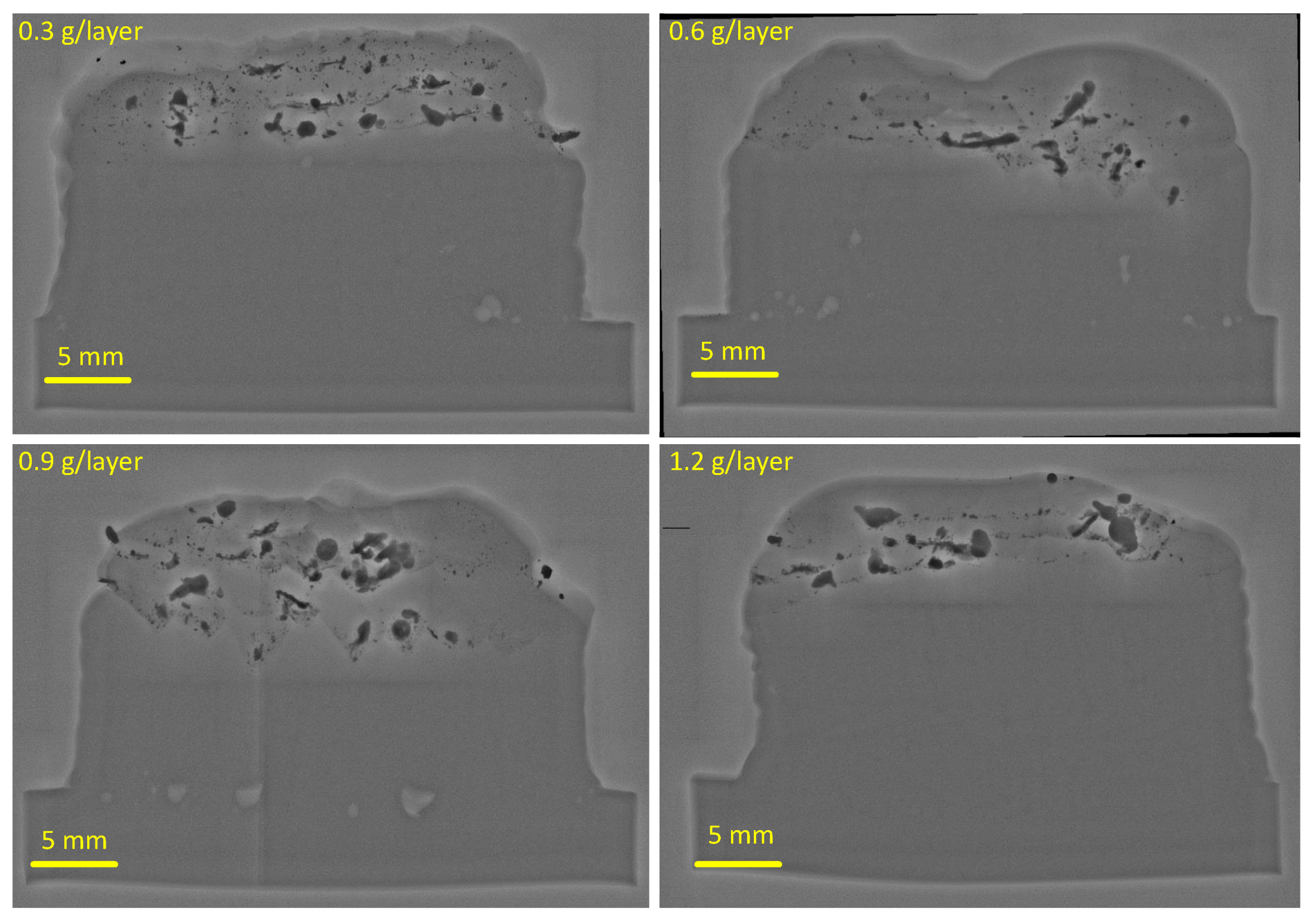
Figure 3.
X-ray tomography cross section positive images of the Zone 2 structures as-viewed from the direction parallel to that of layer deposition. Dark and light-grey areas reveal Mo-rich areas and pores, respectively.
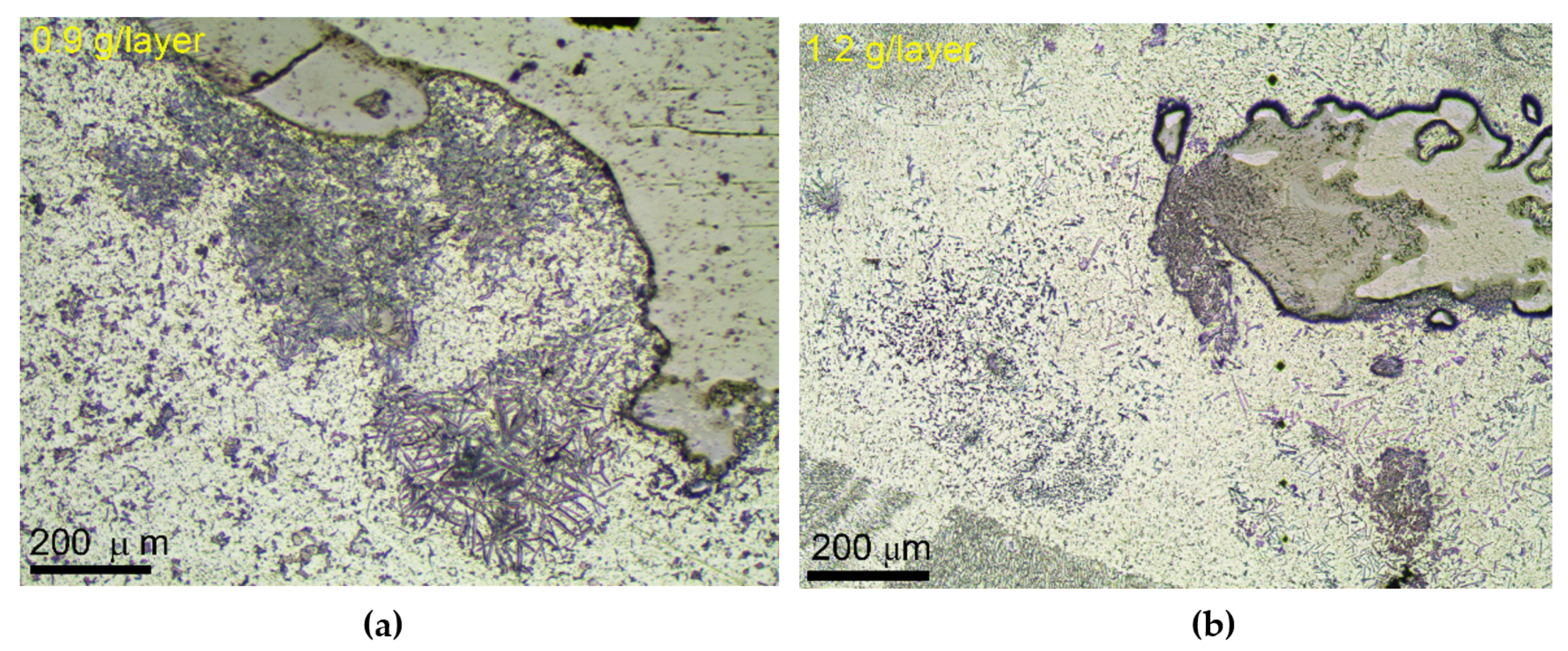
Figure 4.
AA5154/Mo IMCs formed near the Mo-rich particles in 0.9 g/layer (a) and 1.2 g/layer (b) samples.
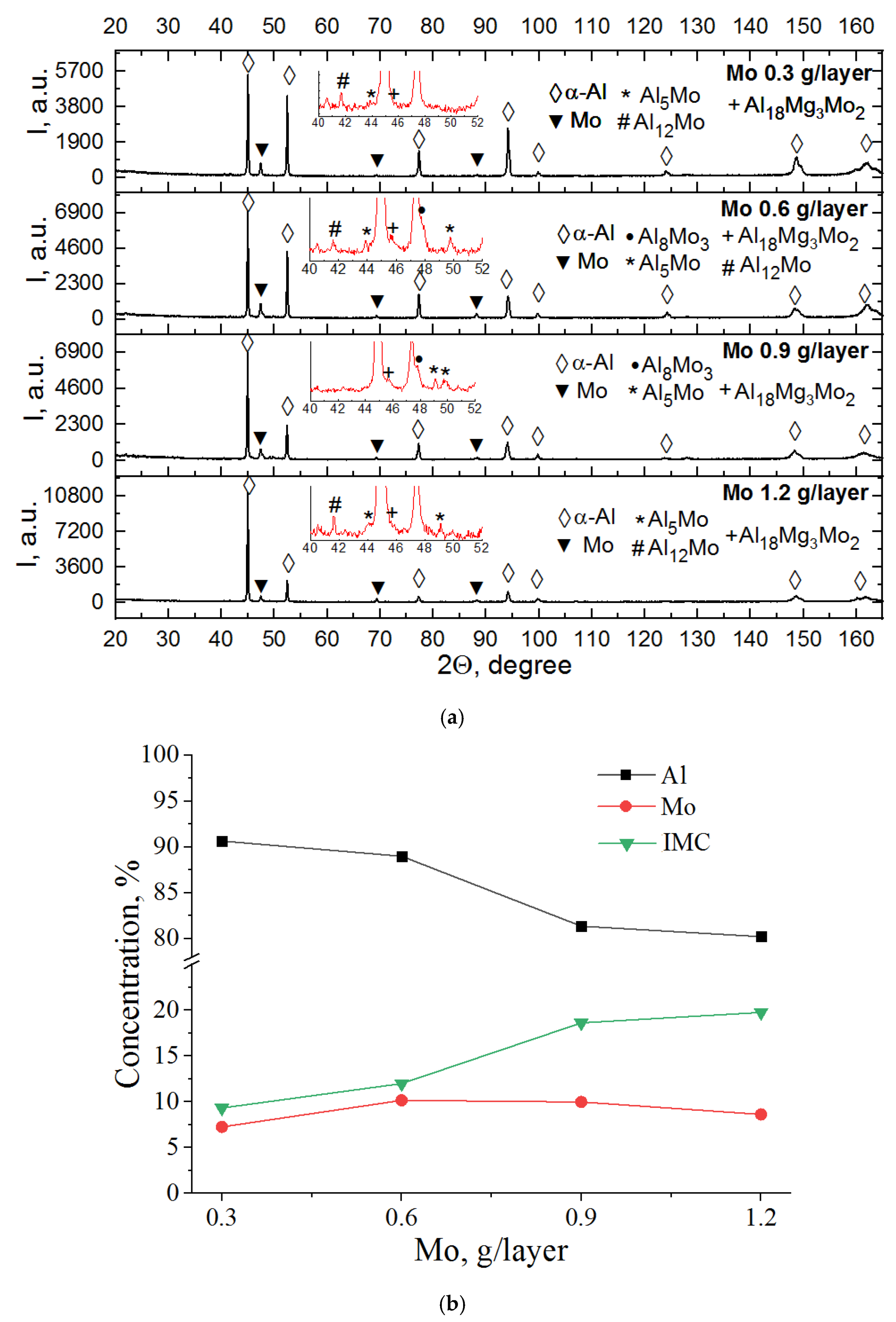
Figure 5.
XRD diffractograms (a) and volume fractions of structural components (b) as depending on the Mo powder bed input.
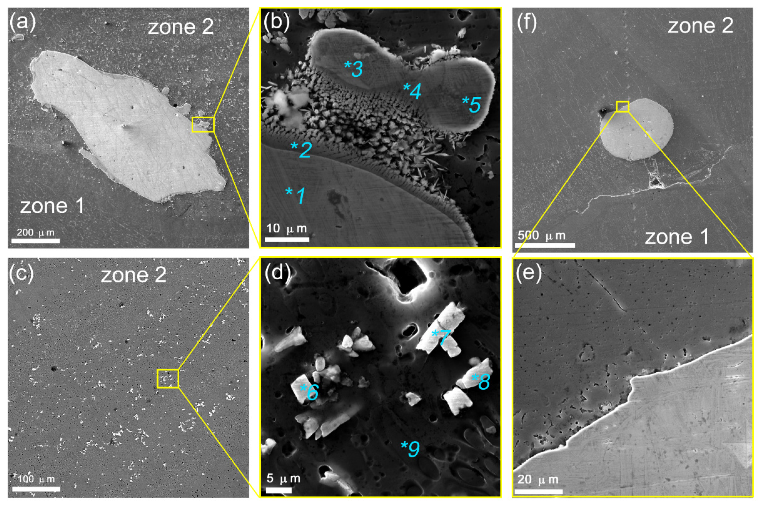
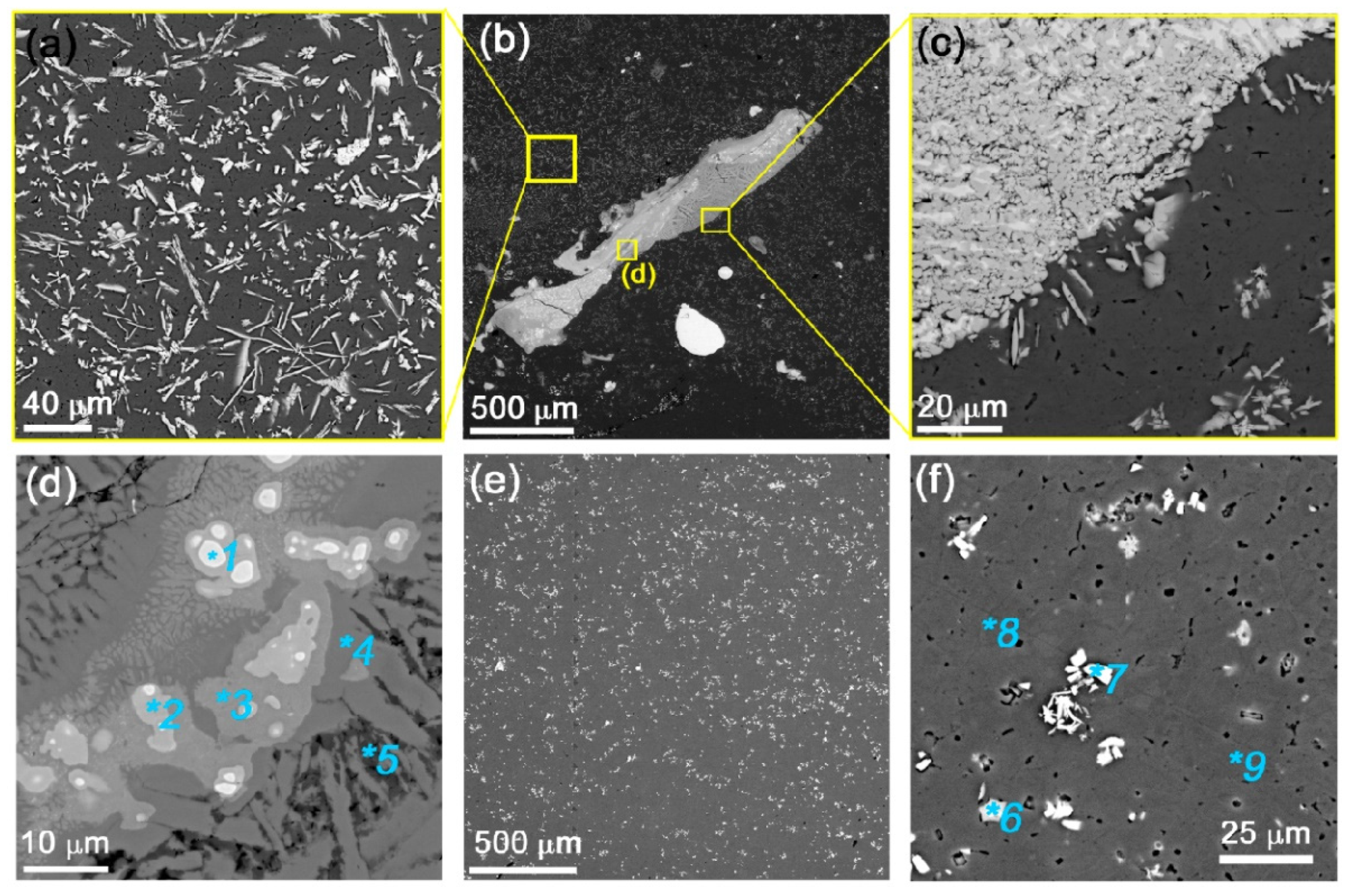
Figure 6.
SEM BSE images of zone 2 AA5154/Mo coarse Mo particles (
a,
c,
f),and enlarged views of IMCs formed around the coarse particles (
b,
d,
e) in the 0.3 g/layer Mo sample. 1–9 denote points selected for EDS (
Table 2).
Figure 7.
SEM BSE image and EDS maps of zone 2 AA5154/Mo microstructures obtained with 0.3 g/layer Mo (
a–
f). TEM images (
g–
j) and SAED pattern showing the IMCs formed. Numbers 1–7 denote points selected for EDS (
Table 3).
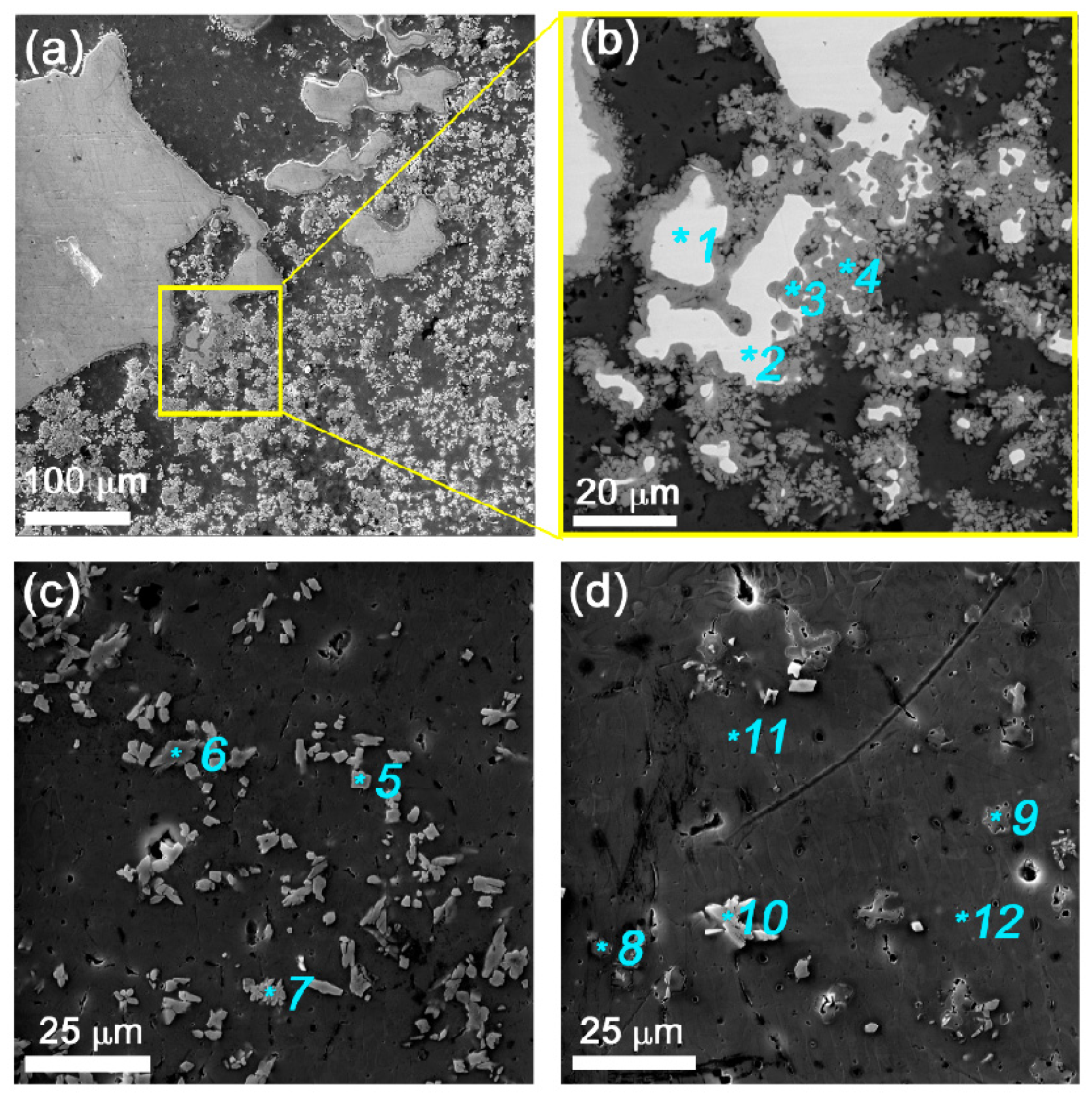
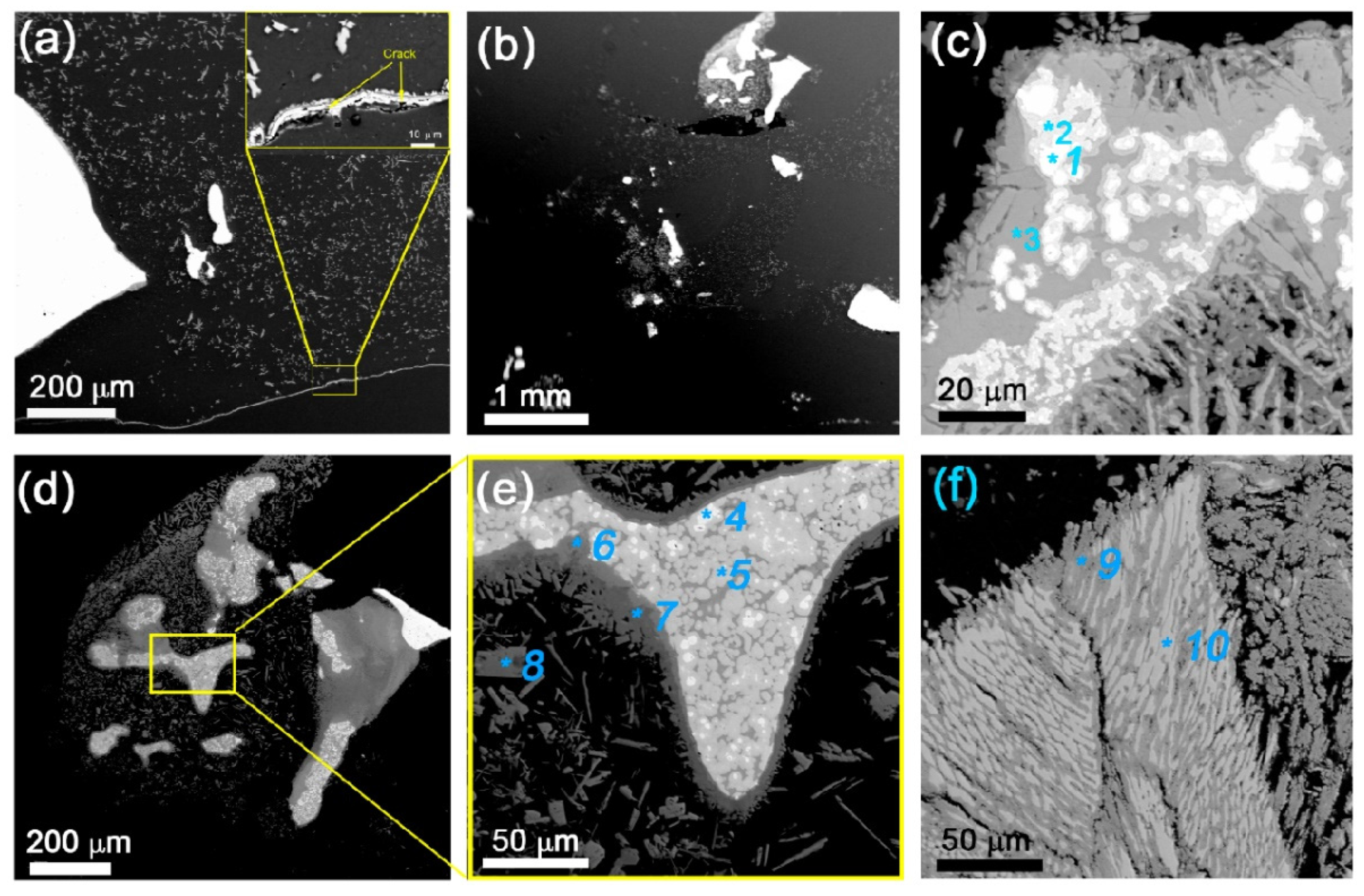
Figure 8.
SEM BSE images of zone 2 AA5154/Mo microstructures obtained with 0.6 g/layer Mo (
a–
d). Numbers 1–11 denote point selected for EDS (
Table 4).
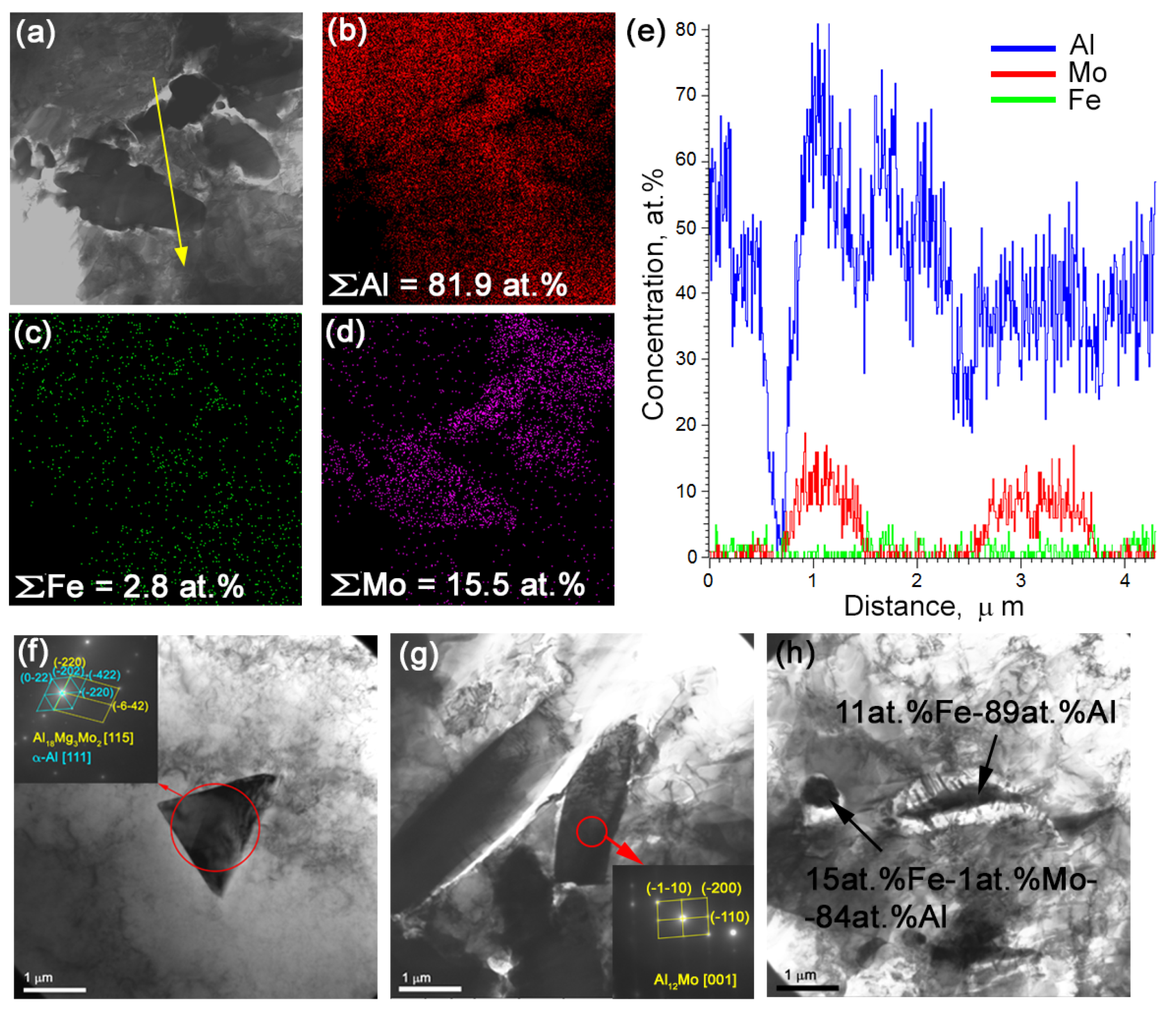
Figure 9.
Bright-field TEM image (
a) and EDS maps (
b–
d) of zone 2 microstructures obtained with 0.6 g/layer Mo. EDS profile along the line in
Figure 8a (
e), and TEM images of IMCs (
f–
h).
Figure 10.
SEM SE (
a,
c) and BSE (
b,
d–
f) images of zone 2 AA5154/Mo microstructures obtained with 0.9 g/layer Mo. Numbers 1–9 denote point selected for EDS (
Table 5).
Figure 11.
SEM SE (
a,
c) and BSE (
b,
d–
f) images of zone 2 AA5154/Mo microstructures obtained with 1.2 g/layer Mo. 1–10 denote points selected for EDS (
Table 6).
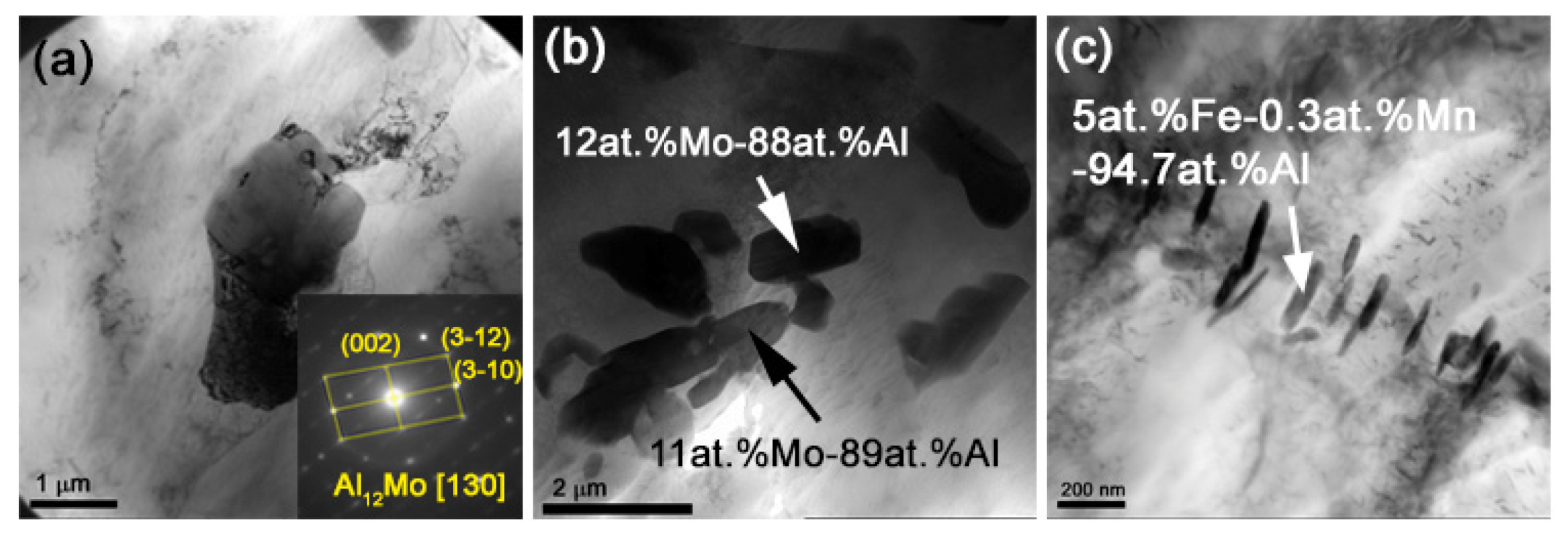
Figure 12.
TEM bright-field images of zone 2 AA5154/Mo microstructures obtained with 0.9 g/layer (a) and 1.2 g/layer (b,c) Mo.
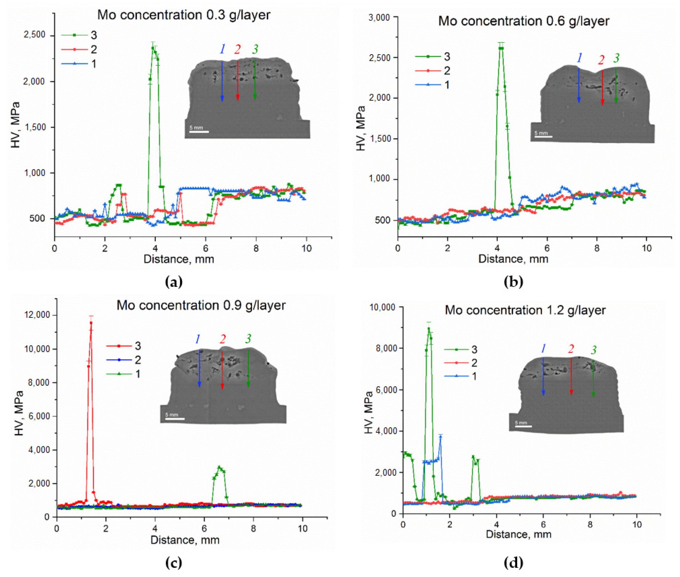
Figure 13.
Microhardness profiles obtained along the lines shown in the insets 0.3 g/layer Mo (a), 0.6 g/layer Mo (b), 0.9 g/layer Mo (c) and 1.2 g/layer Mo (d).
Figure 14.
Coefficient of friction vs. time dependencies of samples.
Figure 15.
Wear of the composite layers obtained.
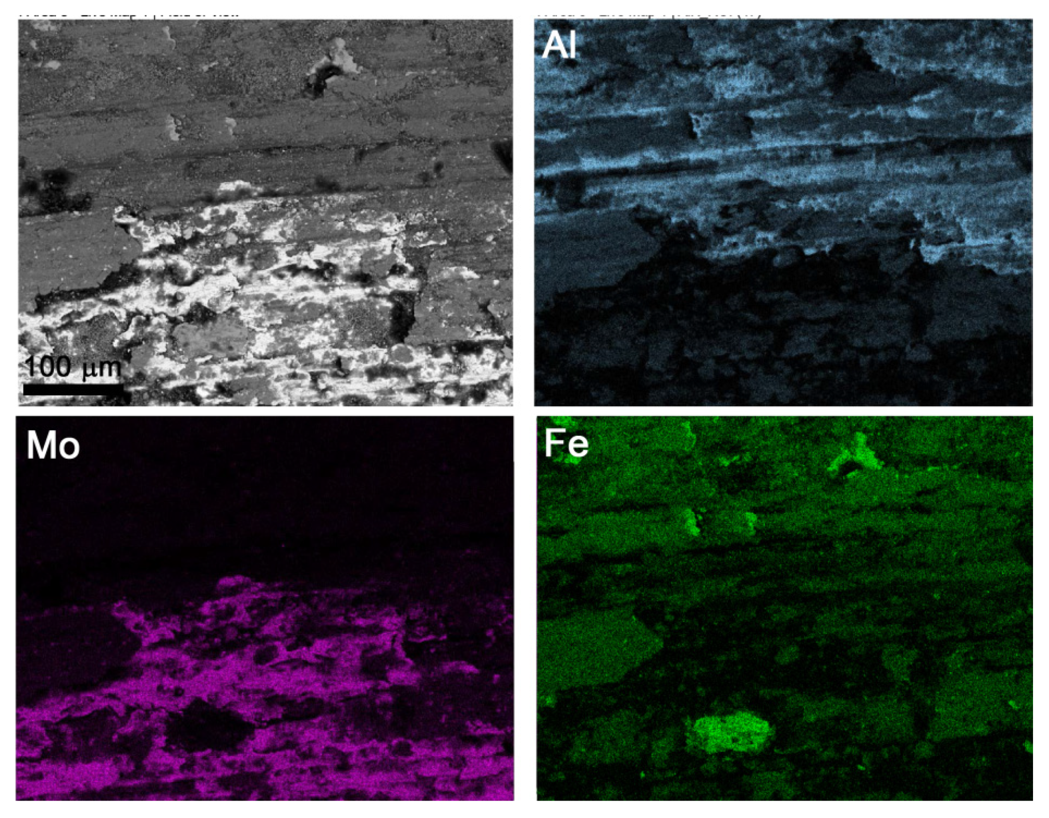
Figure 16.
Mo-rich areas on the worn surface of 0.9 g/layer sample.
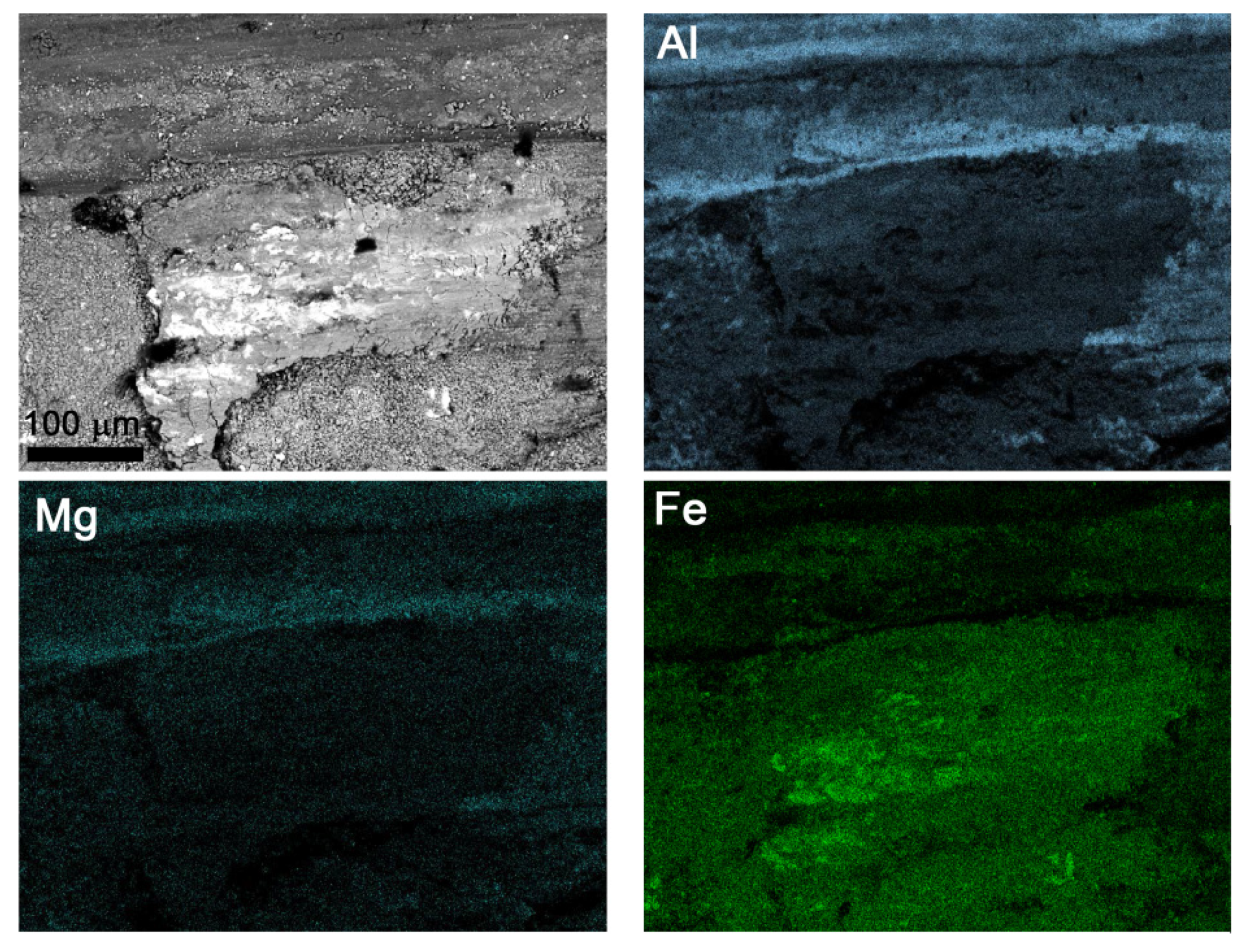
Figure 17.
Fe-rich areas on the worn surface of 1.2 g/layer sample.
Figure 18.
The glancing X-ray diffractograms of worn surface of AA5154/Mo with incidence angle 10°.
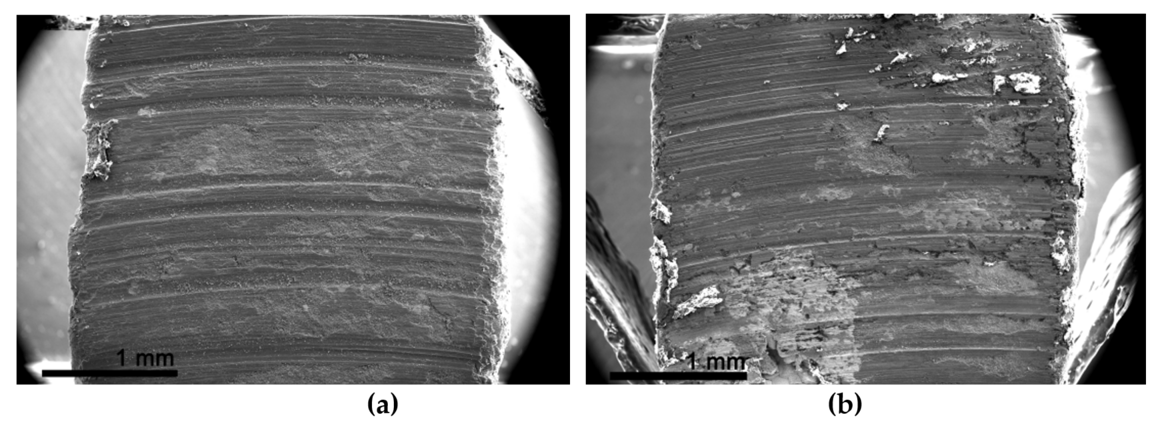
Figure 19.
The worn surfaces of: (a) 0.6 g/layer sample; (b) 0.9 g/layer sample.
Table 1.
The additive process parameters.
| Acceleration Voltage, kV | Beam Current, mA | Wire Feed Rate, mm/min | Table Speed, mm/min |
|---|
| 30 | 40 | 1590 | 380 |
Table 2.
EDS analysis of the AA5154/Mo with 0.3 g/layer was obtained by using SEM (
Figure 6b,d).
| Spectrum | Concentration of Elements, at.% | Calculated Phase |
|---|
| Al | Mo | Mg | Ti | Fe | Mn |
|---|
| 1 | 5 | 95 | - | - | - | - | Mo(Al) |
| 2 | 69.3 | 30.7 | - | - | - | - | Al8Mo3 |
| 3 | 35.6 | 64.4 | - | - | - | - | Al8Mo3 |
| 4 | 82.2 | 17.8 | - | - | - | - | Al5Mo |
| 5 | 66.2 | 33.8 | - | - | - | - | Al8Mo3 |
| 6 | 89.6 | 8.8 | 0.4 | 0.2 | 0.1 | 0.4 | Al12Mo |
| 7 | 87.7 | 10.1 | 0.4 | 0.2 | 0.5 | - | Al12Mo |
| 8 | 87.8 | 10.9 | 0.4 | 0.2 | - | 0.2 | Al12Mo |
| 9 | 98.9 | 0.3 | 0.7 | 0.1 | - | - | α-Al |
Table 3.
EDS analysis of the AA5154/Mo with 0.3 g/layer was obtained by using TEM (
Figure 7g–j).
| Spectrum | Concentration of Elements, at.% | Calculated Phase |
|---|
| Al | Mo | Mg | Ti | Fe | Mn |
|---|
| 1 | 76.8 | 8.3 | 14.9 | - | - | - | Al18Mg3Mo2 |
| 2 | 87.6 | - | 0.8 | 1.4 | 9.9 | 0.3 | Fe-containing phase |
| 3 | 84.1 | - | 0.6 | 1.2 | 13.8 | 0.3 | Fe-containing phase |
| 4 | 98.2 | - | 1.8 | - | - | - | α-Al |
| 5 | 86.8 | 4.5 | 8.1 | - | 0.5 | 0.1 | Al18Mg3Mo2 |
| 6 | 83.9 | 4.0 | 7.8 | - | 3.9 | 0.2 | Fe-containing phase |
| 7 | 98.5 | 0.4 | 1.1 | - | - | 0.3 | α-Al |
Table 4.
EDS analysis of the AA5154/Mo with 0.6 g/layer was obtained by using SEM (
Figure 8b–d).
| Spectrum | Concentration of Elements, at.% | Calculated Phase |
|---|
| Al | Mo | Mg | Ti | Fe | Mn |
|---|
| 1 | 2.5 | 97.5 | - | - | - | - | Mo(Al) |
| 2 | 2.5 | 97.5 | - | - | - | - | Mo(Al) |
| 3 | 83.8 | 16.7 | 0.3 | 0.1 | 0.1 | - | Al12Mo |
| 4 | 82.1 | 17.6 | 0.2 | 0.2 | 0.1 | - | Al12Mo |
| 5 | 87.3 | 11.8 | 0.2 | 0.3 | 0.1 | 0.3 | Al12Mo |
| 6 | 86.7 | 12.6 | - | 0.3 | 0.1 | 0.3 | Al12Mo |
| 7 | 86.9 | 12.4 | - | 0.3 | 0.1 | 0.3 | Al12Mo |
| 8 | 92.5 | 6.7 | 0.1 | 0.1 | 0.2 | 0.4 | α-Al(Mo) |
| 9 | 93.2 | 6.5 | - | 0.1 | 0.2 | - | α-Al(Mo) |
| 10 | 86.8 | 13 | - | 0.1 | 0.1 | - | Al12Mo |
| 11 | 99.7 | 0.2 | 0.3 | - | - | - | α-Al |
| 12 | 99.4 | 0.2 | 0.3 | 0.1 | - | - | α-Al |
Table 5.
EDS analysis of the AA5154/Mo with 0.9 g/layer was obtained by using SEM (
Figure 10d,f).
| Spectrum | Concentration of Elements, at.% | Calculated Phase |
|---|
| Al | Mo | Mg | Ti | Fe | Mn |
|---|
| 1 | 7.6 | 92.4 | - | - | - | - | Mo(Al) |
| 2 | 49.5 | 50.5 | - | - | - | - | Al8Mo3 |
| 3 | 61.9 | 38.1 | - | - | - | - | Al8Mo3 |
| 4 | 72.6 | 27.4 | - | - | - | - | Al17Mo4 |
| 5 | 86.7 | 12.1 | - | - | - | - | Al12Mo |
| 6 | 92.6 | 5.4 | 0.3 | 0.1 | 0.3 | 0.6 | Al12Mo |
| 7 | 87.8 | 10.0 | 0.5 | 0.3 | 0.1 | 0.4 | Al12Mo |
| 8 | 98.5 | | 1.5 | - | - | - | α-Al |
| 9 | 98.2 | 0.1 | 1.6 | - | - | 0.1 | α-Al |
Table 6.
EDS analysis of the AA5154/Mo with 1.2 g/layer was obtained by using SEM (
Figure 11e,f).
| Spectrum | Concentration of Elements, at.% | Calculated Phase |
|---|
| Al | Mo |
|---|
| 1 | 1.6 | 98.4 | Mo(Al) |
| 2 | 52.3 | 47.7 | Al8Mo3 |
| 3 | 61.9 | 38.1 | Al8Mo3 |
| 4 | 1.4 | 98.6 | Mo(Al) |
| 5 | 46.2 | 53.8 | Al8Mo3 |
| 6 | 71.6 | 28.4 | Al17Mo4 |
| 7 | 52.3 | 47.7 | Al8Mo3 |
| 8 | 81.8 | 18.2 | Al5Mo |
| 9 | 43.1 | 56.9 | Al8Mo3 |
| 10 | 65.5 | 33.5 | Al8Mo3 |
Table 7.
Effective Gibbs free energy changes calculated for all Al/Mo phases in AA5154/Mo at 2073 K.
| Compound | Composition | | | | | | |
|---|
| Al12Mo | Al0.923Mo0.077 | −10,700 + 1.865 T | –6.8338 | –5.97 | –3.70 | –5.72 | –6.83 |
| Al5Mo | Al0.833 Mo0.167 | −23,000 + 4.381 T | –13.9182 | –6.02 | –6.41 | –6.41 | –5.88 |
| Al17Mo4 | Al0.810 Mo0.190 | −27,200 + 4.8 T | –16.8350 | –6.62 | –6.62 | –4.84 | –4.67 |
| Al8Mo3 | Al0.728 Mo0.272 | −35,470 + 7.12 T | –20.7102 | –3.71 | –3.93 | –4.19 | –2.96 |
| AlMo3 | Al0.25Mo0.75 | −25,250 + 3 T | –19.031 | –1.95 | –1.95 | –1.95 | –1.95 |
| Publisher’s Note: MDPI stays neutral with regard to jurisdictional claims in published maps and institutional affiliations. |
© 2022 by the authors. Licensee MDPI, Basel, Switzerland. This article is an open access article distributed under the terms and conditions of the Creative Commons Attribution (CC BY) license (https://creativecommons.org/licenses/by/4.0/).


 ,
, 


