Article

Comparative Analysis on the Corrosion Resistance to Molten Iron of Four Kinds of Carbon Bricks Used in Blast Furnace Hearth

1
State Key Laboratory of Advanced Metallurgy, University of Science and Technology Beijing, Beijing 100083, China
2
School of Metallurgical and Ecological Engineering, University of Science and Technology Beijing, Beijing 100083, China
3
WISDRI Handan Wupeng New Lining Material Co., Ltd., Handan 056200, China
*
Author to whom correspondence should be addressed.
Submission received: 27 April 2022 / Revised: 16 May 2022 / Accepted: 17 May 2022 / Published: 20 May 2022
(This article belongs to the Special Issue Fundamentals of Advanced Pyrometallurgy)

Abstract

:
The corrosion resistance to molten iron of four kinds of carbon bricks used in blast furnace hearth were investigated to elaborate the corrosion mechanism through the macroscopic and microscopic analysis of carbon bricks before and after reaction and thermodynamic analysis. The macroscopic analysis showed that brick A had the lowest degree of corrosion and highest uniformity at different heights, attributing to its moderate carbon content of 76.15%, main phases of C, Al2O3, SiC, and Al6Si2O13 (mullite), and lower resistance to molten iron infiltration, etc. The microscopic analysis showed that all the carbon bricks had more and larger pores than the original carbon bricks. The phenomena of the iron beads adhering to carbon brick and iron infiltration were observed between the interface of carbon brick and molten iron. In addition, the obvious corrosion process was presented that the carbon matrix was broken and peeled off during the iron infiltration process. For the carbon brick being corroded, the dissolution of carbon was the predominant reaction. The higher the carbon solubility of the molten iron, the easier the corrosion on the carbon brick. Al2O3 and SiC enhanced the corrosion resistance to molten iron of carbon bricks, and SiO2 could react with carbon to form pores as channels for the penetration of molten iron and increase the corrosion on carbon bricks. A higher graphitization degree of carbon bricks was beneficial to lessen their corrosion degree. The corrosion on carbon bricks by molten iron could be attributed to three aspects: carburization, infiltration, and scouring of molten iron. The carburization process of molten iron was the main reaction process. The molten iron infiltration into the carbon bricks facilitated the dissolution of carbon and destroyed the structure and accelerated the corrosion of the carbon bricks. The scouring of molten iron subjected the iron–carbon interface to interaction forces, promoting the separation of the exfoliated fragmented carbon brick from the iron–carbon interface to facilitate a new round of corrosion process.

1. Introduction

With the continuous development of blast furnaces towards large-scale and high smelting strength, their safety and longevity have been unprecedentedly threatened [1,2,3]. To meet demand, the refractories for blast furnace hearth are constantly updated to adapt to high smelting strength and maintain the safety and longevity of blast furnaces [4,5,6,7]. Among the refractories such as carbon brick, carbon composite brick, corundum brick, and castable, carbon brick is still a dominant refractory, and its corrosion resistance to molten iron and slag, oxidation resistance, and thermal conductivity affect the service life of the hearth. Therein, the corrosion resistance to molten iron is a key link in determining the longevity of the blast furnace. To improve the corrosion resistance, especially the corrosion resistance to molten iron, some carbon brick manufacturers have been making continuous efforts, including adding different additives, such as aluminum powder; improving the microporous properties of carbon brick, such as adjusting the production process; in situ generation of whiskers, such as silicon powder addition; and adding titanium-containing substances to reduce the contact of molten iron and carbon and decrease the update rate of molten iron at the interface, which results in higher mechanical strength, lower porosity sizes, etc., greatly improving the corrosion resistance to molten iron of carbon brick [8,9] and enhancing the compressive strength and thermal shock performance [10,11,12].
Clarifying the influencing factors and mechanism of the corrosion resistance to molten iron of carbon brick can provide theoretical guidance for the carbon brick quality improvement, the carbon brick selection for the blast furnace hearth, and even the adjustment of blast furnace operation so as to prolong the service life of blast furnace hearth. The previous studies on the dissolution of carbonaceous materials in molten iron mainly focus on iron–coke, iron–graphite, etc. [13,14,15,16,17], aiming at enhancing their carburizing ability and optimizing the smelting process. In contrast, few studies on the corrosion of carbon brick in molten iron were reported, especially on the corrosion of the new generation of super-microporous carbon bricks. Deng et al. [18,19,20] investigated the dissolution mechanism of carbon bricks into molten iron; the dissolution reaction of carbon was considered as the dominant reaction and controlled by interfacial reaction and mass transfer of carbon when the phosphorus content was up to 0.2% in molten iron. Stec et al. [21] undertook the molten metal infiltration into micropore carbon refractory materials using X-ray computed tomography; changes were observed in the micropore carbon refractory material’s microstructure, and the elements of the open pore structure that were crucial in molten metal infiltration were identified. Jiao et al. [22] investigated the corrosion behavior of alumina–carbon composite brick in blast furnace slag and iron; the corrosion caused by iron decreased with increasing slag basicity, the dissolution of carbon was one of the corrosion reasons, and the reaction between carbon and silica in the brick could also be promoted by the appearance of iron. With respect to the fact there is scarce and unsystematic research on the corrosion resistance to molten iron of carbon bricks, it is urgent to illustrate the influence mechanism of the chemical composition, physical and chemical properties, and microstructure of carbon bricks on the corrosion resistance performance of different types of carbon bricks in molten iron, allowing the safety and longevity of blast furnace as well as high-efficiency and low-consumption smelting.

2. Experimental

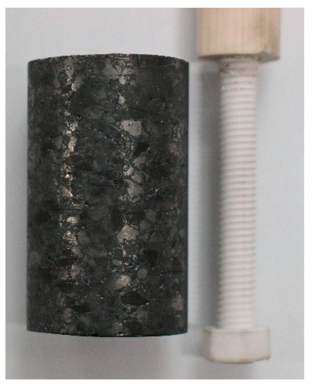
2.1. Sample Preparation

The experimental samples were taken from four types of carbon bricks used extensively in blast furnace hearths worldwide. The chemical composition is presented in Table 1. Among them, A, B, and C are super-microporous carbon bricks, and D is a microporous carbon brick. The carbon bricks were cut into cylinders (φ30 mm × 50 mm) with a concentric and through-hole cylinder using a special drill as shown in Figure 1. To make the surface of the cylinders smooth, they were coarsely ground and finely ground with sandpaper of different particle sizes and then immersed in absolute ethanol for ultrasonic treatment to remove impurities. After cleaning, they were dried in a drying oven at 105 °C for 4 h to avoid the influence of moisture on the experimental results, then stored hermetically for later use. Before the test, the cylinders were inserted into a special ceramic rod to stir the molten iron. The matching ceramic rod is 8 mm in diameter, and its length is determined by the distance between the motor and the molten iron surface. One end of the ceramic rod has a 60 mm long thread and a matching nut as also shown in Figure 1.
Molten iron samples were prepared using reduced iron powder (AR, purity greater than 98%) (Macklin, Shanghai, China), graphite powder (CP, purity greater than 99.85%) (Macklin, Shanghai, China), silicon metal powder (purity greater than 99%) (Sinopharm, Shanghai, China), manganese powder (purity greater than 99%) (Aladdin, Shanghai, China), phosphorus powder (purity greater than 99%) (Alfa Aesar, Shanghai, China), and FeS2 powder (AR, purity greater than 99%) (Rhawn, Shanghai, China). The composition of molten iron is preset as shown in Table 2. The mixture of 770.77 g molten iron sample was ground in the mortar to increase the contact between the particles and ensure that the mixture was thoroughly blended.

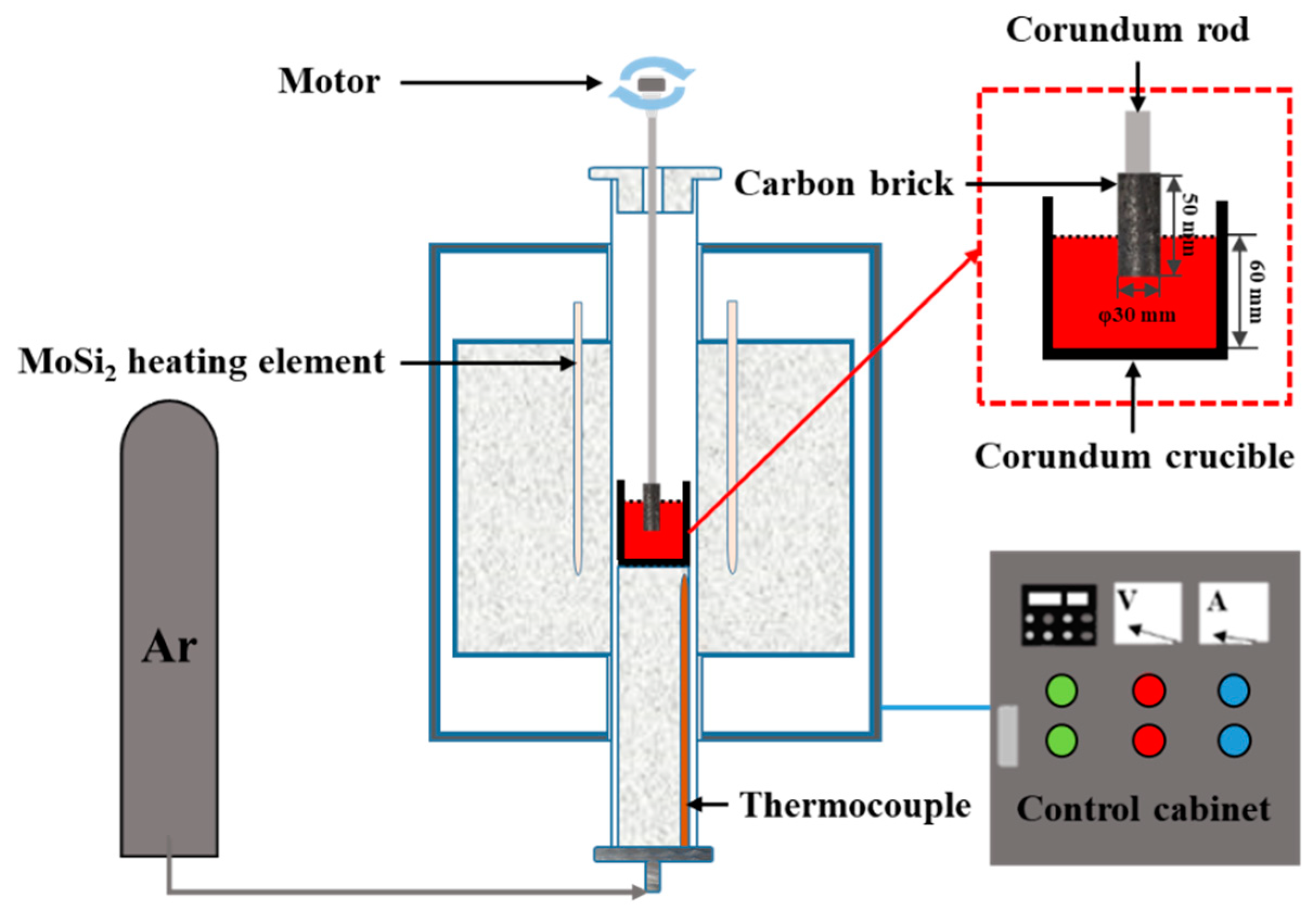
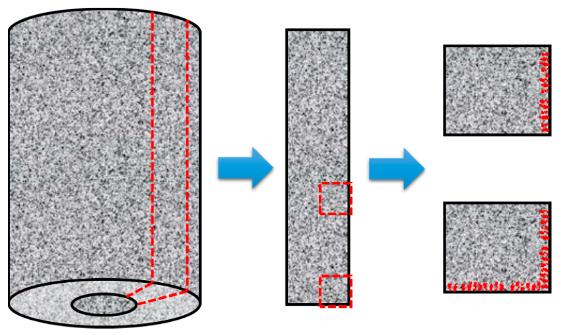
2.2. Experimental Apparatus and Procedure

The experimental apparatus is described in Figure 2. It mainly includes a BLMT–1700 °C high-temperature tube furnace (BLMT, Luoyang, Henan, China), argon cylinder, JJ-1B constant-speed electric stirrer, SRS13A precision temperature controller, etc. The Si-Mo heating rods are adopted as the heating element to control the tube furnace temperature from room temperature to 1700 °C at a maximum rate of 5 K/min. The constant temperature zone in the tube furnace is about 100 mm in length. The constant-speed electric stirrer is placed above the tube furnace, the non-threaded end of the ceramic rod is connected to the motor with an electric stirrer to simulate the circulation velocity of molten iron in the hearth by controlling the rotation speed, and the carbon brick sample is immersed in the molten iron to carry out the experiment.
The molten iron sample was compacted into a ceramic crucible with an outer diameter of 62 mm, a height of 300 mm, and a wall thickness of 3 mm, and then placed in the middle of the constant temperature zone to prevent adhesion to the sidewall of the ceramic furnace tube. The high-purity argon gas (99.9%) was purged into the furnace tube throughout the experiment at a flow rate of 3 L/min. When the tube furnace was heated to 1500 °C, the temperature was maintained for 60 min and the molten iron stirred with a quartz tube to ensure the complete melting and uniformity of the sample. After 40 min of constant temperature, the carbon brick sample was put into the furnace tube above the molten iron to preheat for 20 min, then was slowly submerged to 30 mm below the molten iron surface. The experiment was started after setting the stirring speed to 60 r/min and the time to 120 min. During the experimental process, the molten iron was extracted 3~5 g using a quartz tube with 4 mm in inner diameter every 30 min, and then water quenched quickly for carbon content detection. When extracting molten iron samples, the rotation of the stirring motor was suspended, and the extraction time was controlled within 1 min. After the experiment, the carbon brick sample was lifted 50 mm to separate from the molten iron, and the motor was turned on for 5 min to shake off the molten iron attached to the surface of the carbon brick sample. When the furnace temperature dropped to room temperature, the carbon brick sample was taken out for subsequent characterization.

3. Results and Discussion

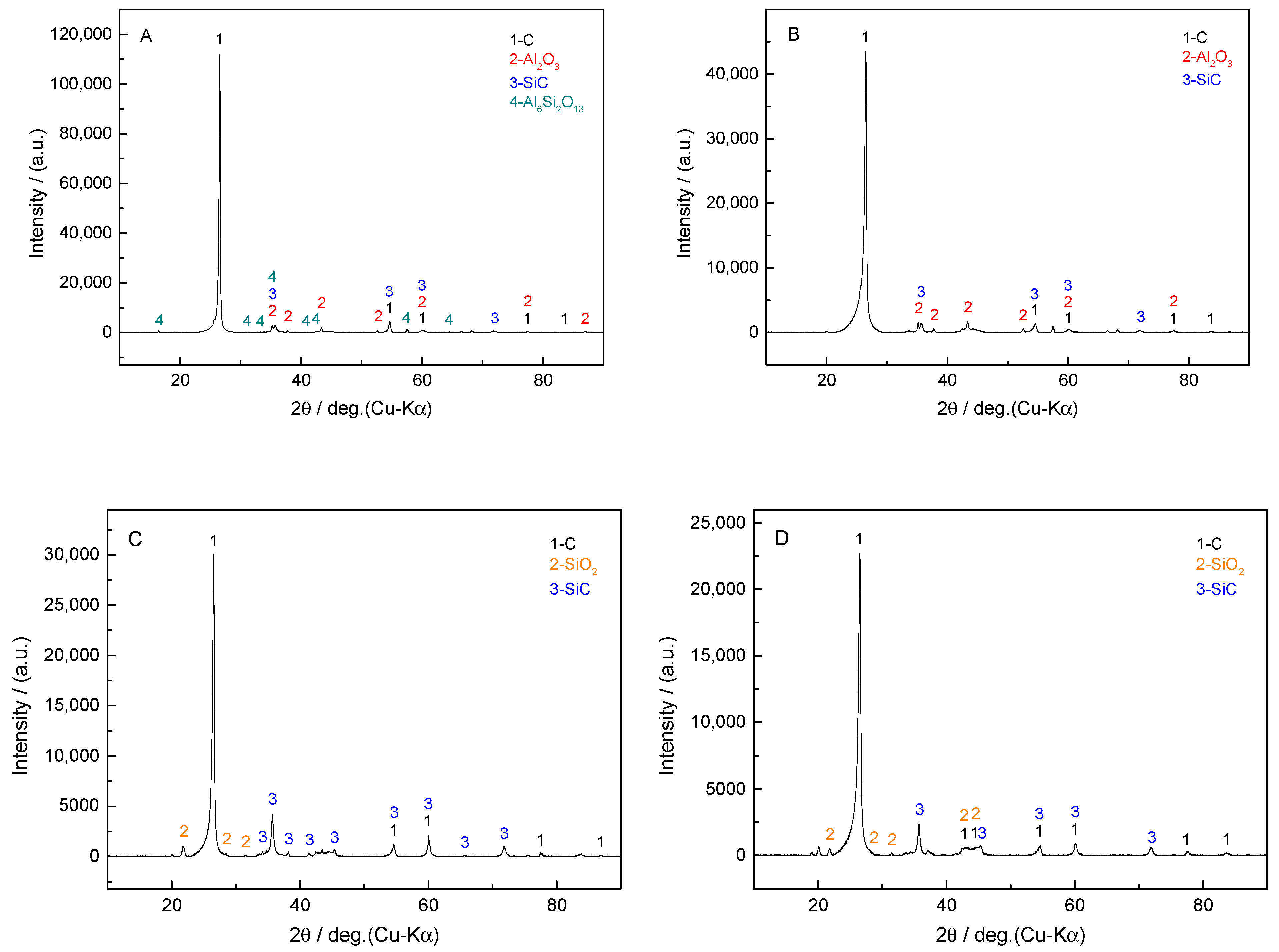
3.1. Analysis of the Original Carbon Bricks

It can be seen from Table 1 that B has the highest proportion of carbon component, which is much larger than the other three types of carbon bricks. Ceramic additives such as Al2O3, SiO2, and SiC in A and B are added in larger amounts; the content of SiO2 in B is relatively high, and the proportion of Al2O3 in A is relatively high. The components of C and D are obviously different from A and B. C and D have less Al2O3, and SiO2 and SiC are the main ceramic additives. From the XRD patterns (Rigku SmartLab, Japan) in Figure 3, it can be determined that the main phases in A are C, Al2O3, SiC, and Al6Si2O13 (mullite), the ones in B are C, Al2O3, and SiC, while the main phases of C and D are C, SiO2, and SiC. Due to the non-uniformity of carbon brick composition and the relatively low content of SiO2 in A and B, the SiO2 phase in A and B is not detected, while Al6Si2O13 phase is detected in A. The physical and chemical properties of these carbon bricks are listed in Table 3. The apparent porosity of A and B is higher than that of C and D, while the pore volume (<1 μm) of A is superior to C and D, which helps to prevent the penetration of molten iron into the carbon bricks. Therefore, the resistance to molten iron infiltration of A is lower than that of the other three carbon bricks. The thermal conductivity of A and B is also superior to C and D.

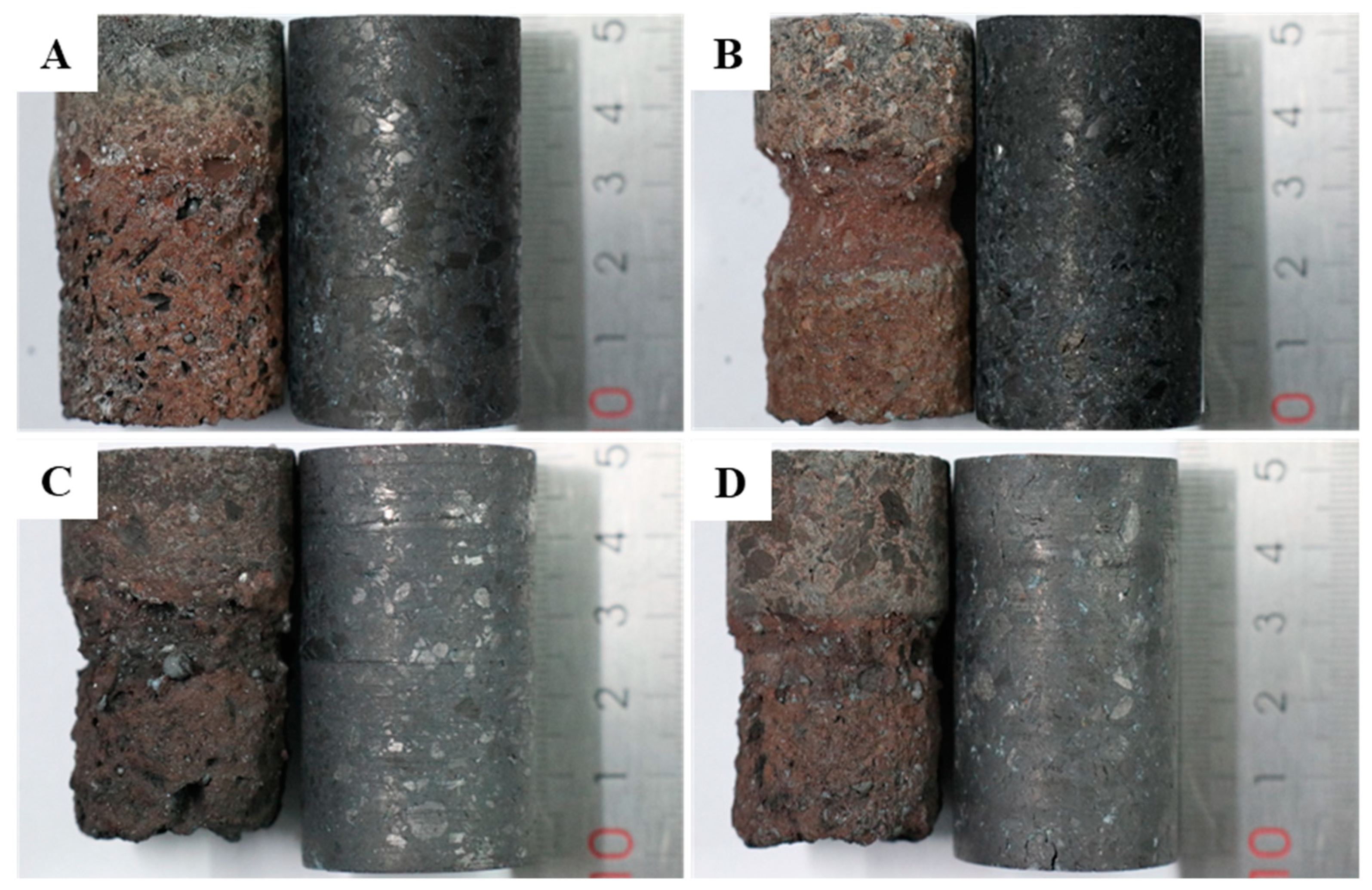
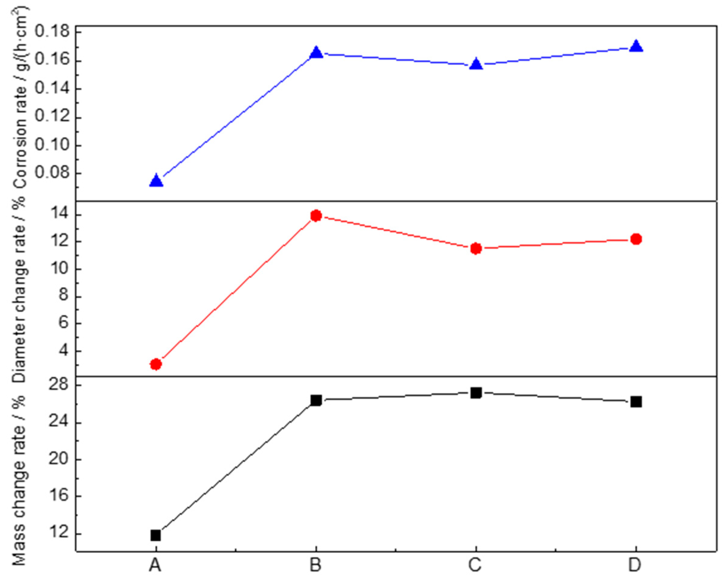
3.2. Experimental Results

The macroscopic morphology of carbon bricks before and after corrosion by molten iron is shown in Figure 4. Obvious appearance differences were observed on the carbon bricks after corrosion under laboratory conditions.
The surface of the original brick A is the smoothest and densest, with larger carbon aggregates in a compact distribution. The surface of the original brick B is relatively rough with many tiny holes of a relatively shallow depth, and the carbon aggregate particles are relatively small. The surface of the original bricks C and D is relatively smooth and dense, but a few micro-cracks are exhibited. The micro-cracks on the surface of D are more prominent than those on C. A has the lowest corrosion degree, with small variation in the diameter of the partial brick immersed into molten iron and uniformity in the corrosion degree at different heights, while a large number of holes are formed on the surface due to the shedding of carbon aggregates. The surface of B is smoother than A after corrosion, and no obvious pores are evident on the surface, but the corrosion is severe at the gas–refractory–iron three-phase interface, showing curved recesses. After being eroded, irregular surfaces appear on C and D, the degree of corrosion is between A and B, and there exists lighter corrosion characteristics of three-phase interface. It also should be noted that C adheres to more iron beads.
The weight and average diameter of carbon bricks before and after corrosion were measured. The mass change rate, diameter change rate, and corrosion rate are defined as follows:
η = m 0 m f m 0 × 100 %
Δ d = d 0 d f d 0
v = π × l × ( d 0 2 d f 2 ) × ρ × w C 400 × t × S
where η is the mass change rate, %; m0 is the weight of carbon brick before the experiment, g; mf is the weight of carbon brick after corrosion, g; ∆d is the diameter change rate, %; d0 is the diameter of the carbon brick before experiment, mm; df is the diameter of the carbon brick after corrosion, mm; ν is the corrosion rate of carbon brick, g/(h·cm2); l is the depth of carbon brick immersed in molten iron, cm; ρ is the density of carbon brick, g/cm3; wC is the carbon content of carbon brick, %; t is the reaction time, h; and S is the reaction area, cm2.
It can be seen from Figure 5 that the mass change rate, diameter change rate, and corrosion rate of A are far lower than those of the other three carbon bricks, indicating that A possesses better corrosion resistance to molten iron and has a good positive effect on prolonging the life of the blast furnace.

3.3. Microscopic Analysis of Reaction Interface

The original carbon bricks were randomly sampled from the whole carbon brick for microscopic observation by scanning electron microscope (SEM) (FEI Quanta 250, Holland) on the original morphology, structure characteristics, and phase distribution, etc. The samples after corrosion were cut along the axis of the concentric cylinder, and the outer surfaces, including three-phase interface and refractory–iron interface, were also subjected to microscopic characterization as Figure 6 shows.

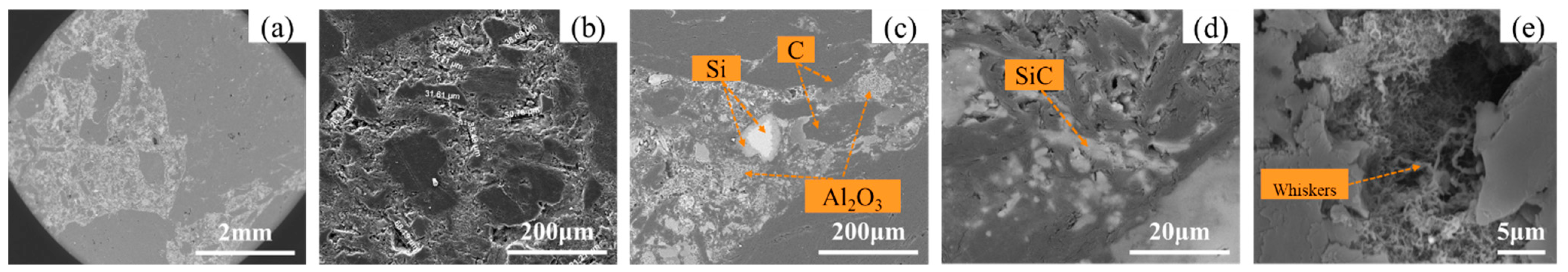
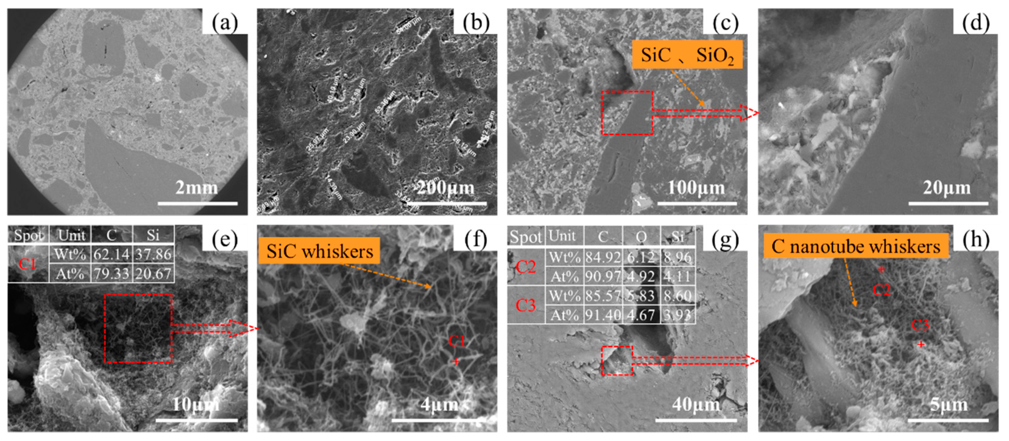
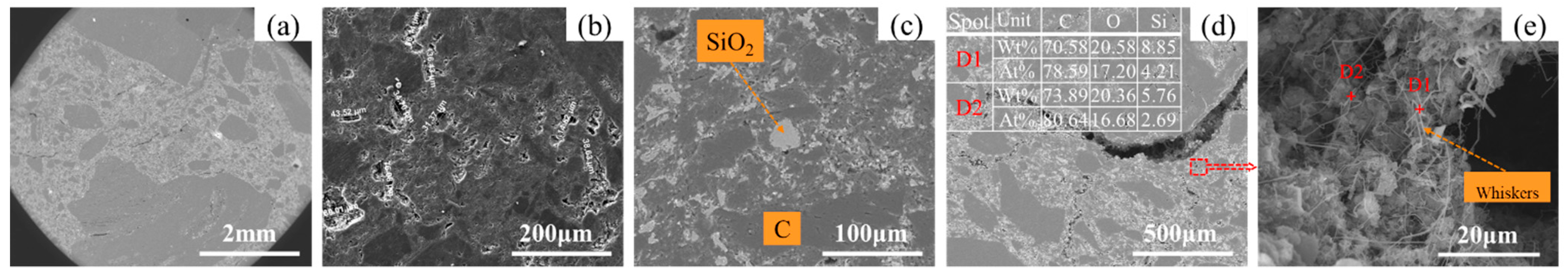
3.3.1. Analysis of the Microscopic Appearance of the Original Carbon Brick

The microscopic morphology of the original brick A is taken under different scaleplates, as shown in Figure 7. It can be seen from Figure 7a that the boundaries between the carbon matrix, white ceramic, and black carbon aggregates are obvious. The internal surface is rough, with more micro-pores in size of 20~70 μm as presented from Figure 7b. From Figure 7c,d, it indicates the dispersed distribution of ceramic in the carbon matrix, thereby avoiding the adverse effect of the single ceramic assemblage on the thermal conductivity of the carbon brick. The local carbon matrix and mineral layer are in a strip shape, which isolate the carbonaceous aggregates at different locations. This phase distribution can effectively block the contact between the carbon aggregate and the molten iron at the iron–carbon interface during the dissolution process and slow down the dissolution process of carbon brick. Some whiskers are found in the pores of A, as shown in Figure 7e.
As a large amount of flake graphite is added to B to boost the thermal conductivity, the carbon content is relatively high, which meets the chemical composition in Table 1. B contains less ceramic seen from Figure 8a compared with A. The boundary of the black carbon aggregate layer is not obvious, so the overall interface is mainly carbon matrix with the ceramic dispersed and discontinuous distribution, as shown in Figure 8c. From the secondary electron image in Figure 8b, it can be observed that the surface of B is smooth with fewer micro-pores; those it does have are mostly in the size range of 20~50 μm. On the other hand, there are many pores on the surface of the original brick under the scaleplate of 2 mm with larger depth, as shown in Figure 8a. It shows another distribution of the ceramic additives, Al2O3 in this region performs lamellar. Similarly, higher silicide is located in the interface between Al2O3 and the carbon matrix.
The microscopic morphology of the original brick C is shown in Figure 9. As seen from Figure 9a, it exhibits more dispersed distribution of ceramic additive and a greater number of small-sized carbon aggregates compared with that in A and B, and an obvious boundary between the carbon aggregate and the non-aggregate is observed. There are cracks on the surface of the original brick C, while the number of micropores is relatively few with thin and long feature. It is discovered from Figure 9c that the ceramic additives are mainly silicon compounds, which meet the chemical composition in Table 1. The SiO2 and SiC ceramic phases are uniformly distributed in the carbon matrix, and there is no Al2O3 aggregation on the surface.
There exists a mass of flocculent whiskers in the pores of the original brick C as presented in Figure 9c,d, covering the inner walls of the pores. Further magnified in Figure 9e,f, we may see the whiskers connect to each other and form a network structure, filling the pores of the carbon brick. By spot scanning, we can ascertain the whiskers mainly contain two elements: C and Si, indicating that this area is dominated by SiC whiskers. The whiskers in the pores of the carbon aggregates are shown in Figure 9g,h. By spot scanning C2 and C3, we find the C element accounts for >90%. Combined with the brick composition and production process design, it can be inferred that the whiskers in this area are mainly carbon nanotubes.
The microscopic morphology of the original brick D is shown in Figure 10; in comparison with C, denser and larger pores on the surface are confirmed in Figure 10a,b with the size mainly ranging from 30 μm to 50 μm. Through the comparative analysis of Figure 9c and Figure 10c, it can be found that the internal density of D is lower than that of C. A large number of whiskers are found inside of the crack at the junction of the carbon aggregate and the carbon matrix, shown in Figure 10e. By EDS analysis of spots D1 and D2, we find the main component of the whiskers is carbon, and they contain a small amount of Si element. Combined with the brick composition and production design, the whiskers can be deduced to be mainly carbon nanotubes, and part of the SiC whiskers are mixed.

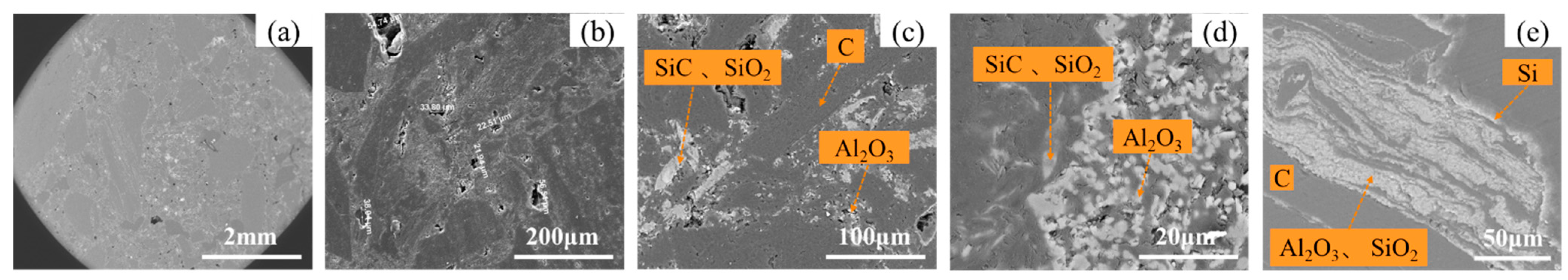
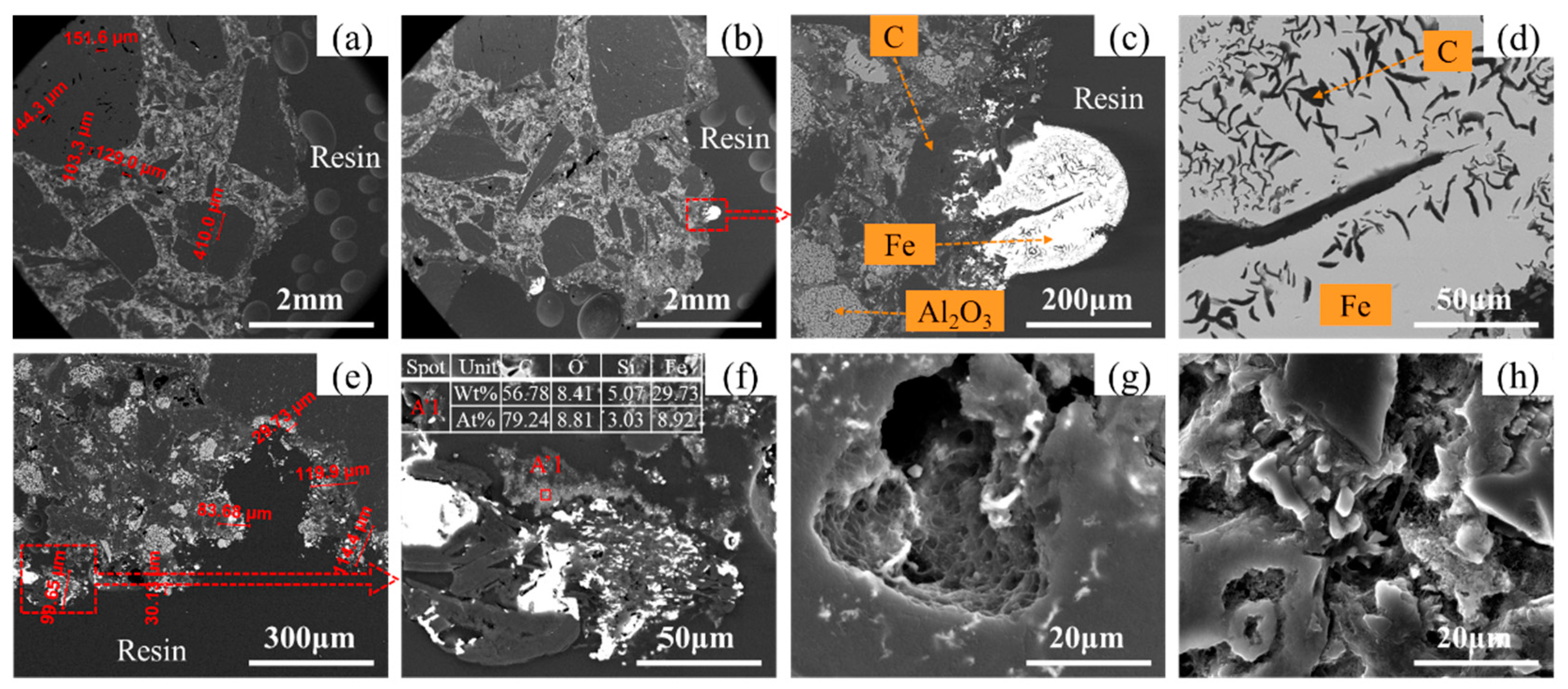
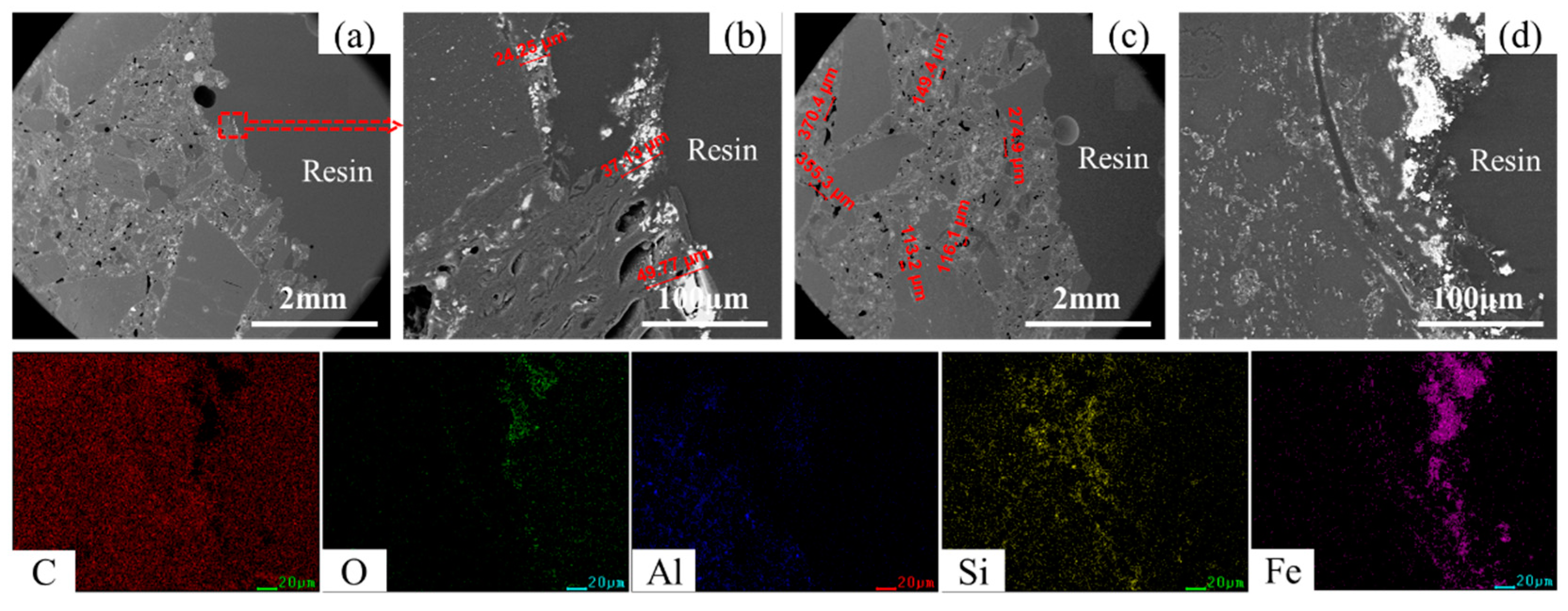
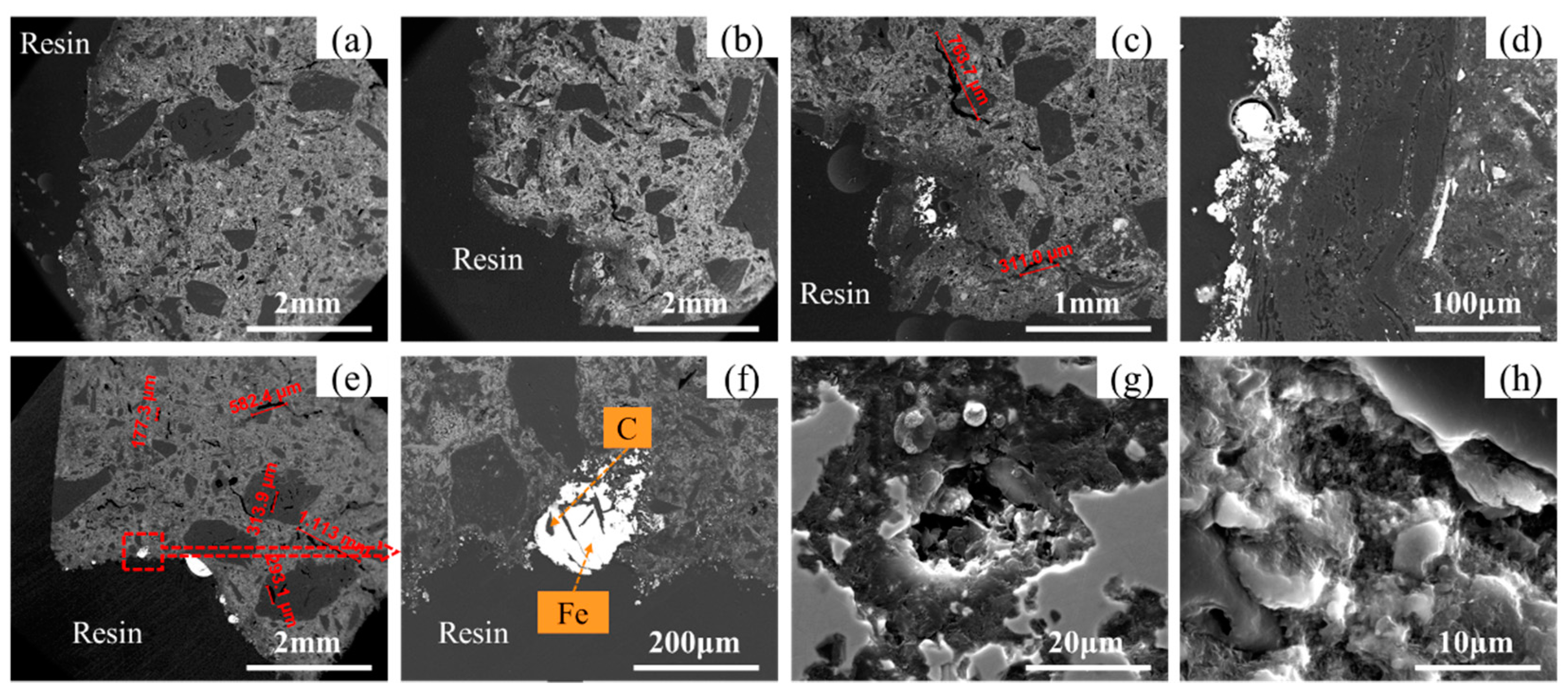
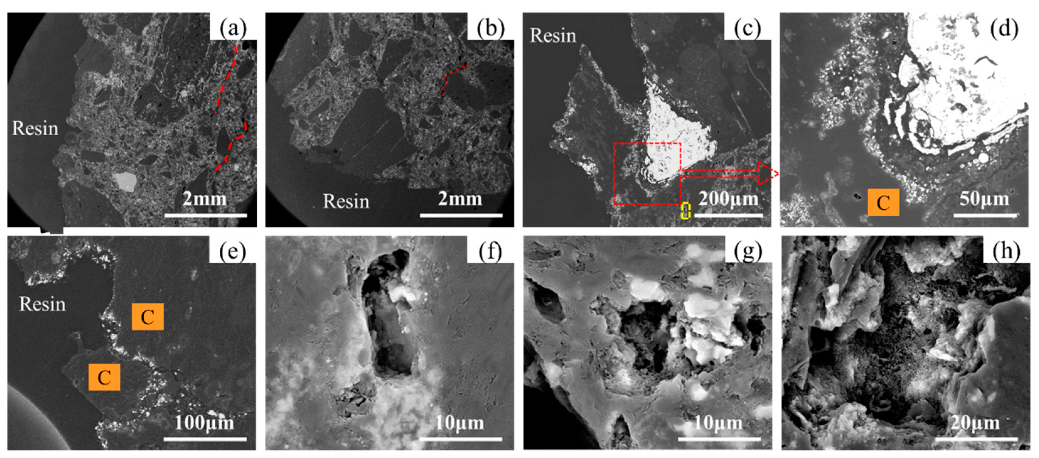
3.3.2. Analysis of the Microscopic Appearance of the Carbon Brick after Corrosion

Figure 11a–d show the microscopic morphology of the side surface of A after corrosion. The uneven morphology is still maintained on the reaction interface as shown in Figure 11a,b. There exist a few cracks and pores on the internal interface, and the pores are mainly concentrated on the surface of the carbon aggregates with the diameter more than 100 μm. The phenomenon of the iron beads adhering to the carbon brick appears on the surface in Figure 11c. The small iron beads mainly gather at the carbon aggregates, and the mixed part of the carbon matrix and the ceramic phase is mainly iron infiltration. As shown in Figure 11d, only strip-shaped carbon aggregates remain in the iron-infiltrated part.
The bottom surface of A immersed in molten iron after corrosion is presented in Figure 11e,f. The reaction interface retains a good iron infiltration phenomenon. This not only adheres to small iron beads but also an iron infiltration layer in the carbon aggregates. The whole iron infiltration layer is between 30 μm and 120 μm, and the thinner thickness of the carbon matrix and ceramic is discovered due to the ceramic presence. It is strong proof that the ceramic material enhances the carbon brick’s resistance to molten iron corrosion and penetration. From Figure 11f, it is found that the small pieces of carbon aggregates have been almost separated by iron infiltration from the carbon matrix; a nebula-like, exfoliated, and dissolved iron–carbon mixture emerges, with 8.92% iron and 56.78% carbon in atomic ratio.
The internal whiskers in the pores close to the reaction interface have been dissolved by molten iron, and the inner surface of the pores is covered by small, dense pits as analyzed from Figure 11g, while a large number of whiskers still exist in the pores away from the reaction interface as shown in Figure 11h. This illustrates that the whiskers in the pores are firstly dissolved by the molten iron, thereby retarding the process of carbon brick being corroded by the molten iron.
The microscopic morphology of B after corrosion is presented in Figure 12. From Figure 12a, an obvious arc is observed at the three-phase interface. Compared with the A corrosion morphology, the reaction interface of B is relatively flat and there are fewer iron beads adhering on the surface, most of which are iron infiltration with thickness nearly 50 μm. In addition, a lot of holes are distributed on the surface of B, the maximum diameter of which can reach 370.4 μm. However, there are very few cracks on the surface of graphite carbon aggregates. From the mapping of the local carbon aggregate in Figure 12d, we can see a small amount of Al2O3 and SiO2 ceramic additives dispersed within. The large-scale cracks in the carbon aggregate itself have iron accumulation; it can be inferred that they will act as a channel for iron penetration when the molten iron is corroded to a certain extent and accelerate the corrosion rate of the carbon brick in this part. Obviously, the number and size of internal pores and cracks in carbon brick have a significant negative impact on its ability to resist molten iron corrosion of carbon brick.
Figure 13a–d show the microscopic morphology of C after corrosion; it can be observed that C has a smaller amount of large-particle carbon aggregates and very few pores in the carbon brick, but many large cracks exist, and the crack length can reach 763.7 μm. What is more, the reaction interface on side surface is relatively flat, gaps appear at the junction of the bottom surface and the side surface, and a large number of iron beads are bonded on the reaction interface in the gap. As shown in Figure 13d, both iron infiltration and iron bead adhesion arise in the carbon aggregates, and the thickness of the iron infiltration layer varies from 50 μm to 100 μm. An iron infiltration zone inside the aggregates can destroy the structure of the carbon brick near the reaction interface and accelerate the subsequent dissolution of the carbon brick in this area.
The microscopic morphology of the bottom surface of C after corrosion is presented in Figure 13e,f, cracks of up to 1.113 mm appear in this area, which will reduce the stability performance of carbon brick. In addition, there is a phenomenon of iron beads adhering to the reaction interface in the area of non-carbon aggregates. The strip-shaped black phases inside the iron beads are deduced to be graphite phase saturated with carbon and graphite aggregate wrapped and isolated during the process of carbon aggregate dissolution by molten iron through EDS analysis. The mixing and contact area of iron bead and carbon brick indicates that, as the penetration of molten iron deepens, the main boundary structure of C is severely damaged, a large number of small particles in carbon brick matrix and carbon aggregate are stripped and accumulate to form a layer of stripped small particles at the reaction interface. Figure 13g,h show the microscopic morphology of the pores near and away from the reaction interface, respectively. It can be observed that the SiC whiskers and carbon nanotube whiskers near the reaction interface have been almost completely decomposed and disappeared, which is similar to the corrosion seen in A.
The microscopic morphology of the side and bottom surface of D after corrosion is shown in Figure 14. Under 2 mm scaleplate, D has a small quantity of pores, while the number of internal cracks is significantly greater compared with C after corrosion, and the crack length can reach more than 2 mm. The phenomenon of iron bead adhering to the reaction interface is not obvious. Figure 14c shows that the iron beads in this area have been embedded in the carbon aggregate, and a certain degree of iron permeation layer at the reaction interface exists. It is foreseeable that, as the molten iron further dissolves and penetrates, the carbon particles bordered by the yellow dashed line will be stripped off. Further enlargement of Figure 14c allows us to observe that the iron beads at this location do not exist in the form of being embedded inside the carbon particles. There is still an iron penetration layer and carbon matrix separation between the iron beads and the carbon particles. Therefore, iron penetration will cause the deterioration of the carbon brick, and then the carbon matrix separates from the structure. Figure 14e shows the microscopic morphology of the carbon aggregate after corrosion; the corrosion of carbon aggregate is not entirely caused by molten iron corrosion. The penetration of molten iron in carbon aggregate will also cause local cracking and stripping of the carbon brick.
The characterization results of the internal pores in the radial direction of D sample are presented in Figure 14f–h. Figure 14f shows the internal pores in the yellow dashed frame in Figure 14c, which are closest to the reaction interface. SiC whiskers, or carbon nanotubes, are not found inside. From Figure 14g,h close to the pores inside D in sequence, only some whiskers exist in the pores in Figure 14g, while a large number of whiskers retain in Figure 14h. Therefore, the presence of whiskers helps to delay partial dissolution of pores when the carbon brick contacts with molten iron.

3.4. Analysis on the Mechanism of Corrosion Resistance to Molten Iron of Carbon Brick

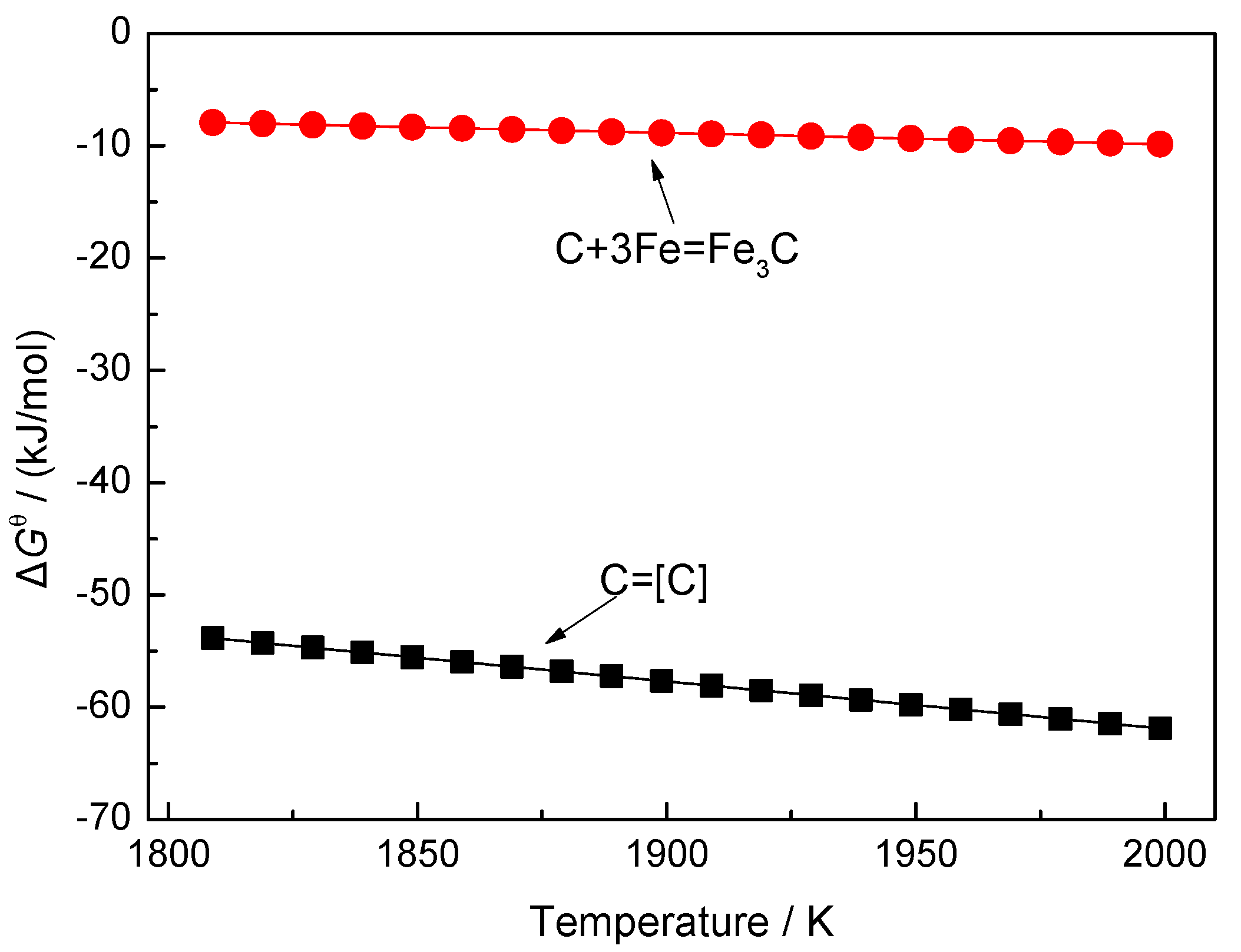
3.4.1. Thermodynamic Analysis

There are two reactions that may occur in the carburization process of molten iron; one is the dissolution of solid carbon into molten iron, and the other is the formation of Fe3C from the reaction of solid carbon and iron atom within the temperature range of 1809 K to 2000 K. According to thermodynamic analysis in Figure 15, the dissolution of carbon is intended to be the predominant reaction.
C ( s ) = [ C ] Δ G θ = 22 , 590 42.26 T , J / mol
C ( s ) + 3 Fe ( l ) = Fe 3 C ( s ) Δ G θ = 10 , 530 10.2 T , J / mol
The carbon content in molten iron is always unsaturated in the production process of blast furnaces. Therefore, the carbon bricks with carbon as the main component will have continuous direct contact with the molten iron to cause carbon dissolution, resulting in carbon brick corrosion. Higher carbon content in carbon bricks can give rise to easier corrosion due to the larger contact area between the molten iron and the carbon in the carbon brick. The molten iron is also in constant motion. The renewal of molten iron will also cause continuous corrosion on carbon bricks. Therefore, the method to reduce the corrosion of carbon bricks by molten iron is centered on the following factors.
(1)
Carbon solubility in molten iron
When the reaction of C(s) = [C] reaches equilibrium, the standard Gibbs free energy of the reaction is:
Δ G θ = R T ln K θ = 2.303 R T lg K θ = 2.303 R T lg a [ C ] = 2.303 R T ( lg [ C ] + lg f C )
lg [ C ] = 1179.81 T + 2.21 lg f C
According to Wagner’s model, the activity coefficient of carbon in multi-system molten iron can be expressed as follows:
lg f C = e C C [ C ] + e C Si [ Si ] + e C Mn [ Mn ] + e C P [ P ] + e C S [ S ]
Combining Equations (7) and (8), we can gain the carbon content in molten iron.
lg [ C ] = 1179.81 T + 2.21 e C C [ C ] e C Si [ Si ] e C Mn [ Mn ] e C P [ P ] e C S [ S ]
where e C j is the activity interaction coefficient of the j element and carbon element in the molten iron.
There are two factors affecting the carbon solubility in molten iron. One is the temperature of the molten iron. The carbon solubility will increase with the increase in temperature under the constant content of each component in molten iron. The other is the product of the content of each component and the activity interaction coefficient of this component and carbon component. When e C j > 0, the activity coefficient of carbon increases with the content of j element increasing, resulting in a decrease in the carbon solubility. When e C j < 0, the activity coefficient of carbon will decrease with the increase in j element, leading to an increase in the solubility of carbon in the molten iron. The carbon solubility in molten iron can reflect the corrosion ability of molten iron on carbon brick, that is, the higher the carbon solubility, the easier the carbon brick is to corrode.
(2)
Ceramic phases and whiskers
Al2O3, SiO2, and SiC are the main ceramic phases contained in the present carbon bricks. Al2O3 cannot react at all at the experimental temperature, and it is not wet with molten iron [23]. Therefore, the addition of Al2O3 enhances the corrosion resistance to molten iron of carbon bricks. SiC is another factor enhancing the corrosion resistance to molten iron, because the special preparation process of carbon bricks can promote the formation of SiC whiskers in situ. The presence of whiskers in the pores will withstand the molten iron, delaying carbon brick corrosion. Carbon nanotube whiskers can also delay the corrosion of carbon bricks to a certain extent, because the channels where molten iron enters the pores will preferentially erode the carbon nanotube whiskers in the pores.
SiO2 can react with carbon to produce FeSi and CO under the catalysis of iron, as Equation (10) shows [24,25]. The pores formed after the reaction will become channels for the penetration of molten iron and increase the corrosion of carbon bricks.
SiO 2 ( s ) + 2 C ( s ) + Fe ( l ) = FeSi + 2 CO Δ G θ = 649 , 404 383.53 T , J / mol
Ceramic additives such as Al2O3, SiO2, and SiC in A and B are added in larger amounts, and the proportion of Al2O3 in A is relatively high. The components of C and D are obviously different from A and B. C and D have less Al2O3, and SiO2 and SiC are the main ceramic additives. Additionally, A also contains some whiskers, so its performance is better.
(3)
Graphitization degree of carbon brick
From Figure 3, the sharp (002) carbon peaks of the four carbon bricks can be clearly observed. The sharper the carbon peak, the higher in the degree of the ordering of carbon structure or graphitization [26]. Generally, the average stacking height (LC) of the layered structure is used to characterize the lattice dimensions of crystalline carbon. LC can be obtained by using the classical Scherrer’s Equation [27,28,29] with crystallites in the absence of lattice strain or distortion.
L C = 0.89 λ B 002 cos ( θ 002 )
where λ is the wavelength of the X-ray radiation, B002 is the full-width at half-maximum intensity of the (002) carbon peak, and θ002 is the diffraction angle of the (002) band. Accordingly, a sharper (002) carbon peak indicates a greater crystalline order or graphitization degree of carbon materials.
Based on Bragg’s law [30], the interlayer spacing (d002) and average layer number (NC) can be calculated as follows:
d 002 = λ 2 sin ( θ 002 )
N C = L C d 002
The calculation results of LC, d002, and NC are shown in Table 4.
The LC and NC values of carbon bricks present in the same order of LC(A) > LC(C) > LC(B) > LC(D) and NC(A) > NC(C) > NC(B) > NC(D), demonstrating a decreasing graphitization degree and crystalline structure of carbon. Moreover, the graphitization degree is almost inversely proportional to the experimental results of the corrosion resistance to molten iron of four carbon bricks, that is, the higher the graphitization degree, the smaller the mass change rate, diameter change rate, and corrosion rate. This demonstrates that the crystalline structure of carbon is closely related to its dissolution behavior in molten iron, and the higher the graphitization degree, the less easily the carbon brick will be corroded. The findings are different from those of previous studies [13,31,32], but are consistent with Guo’s investigation [33].

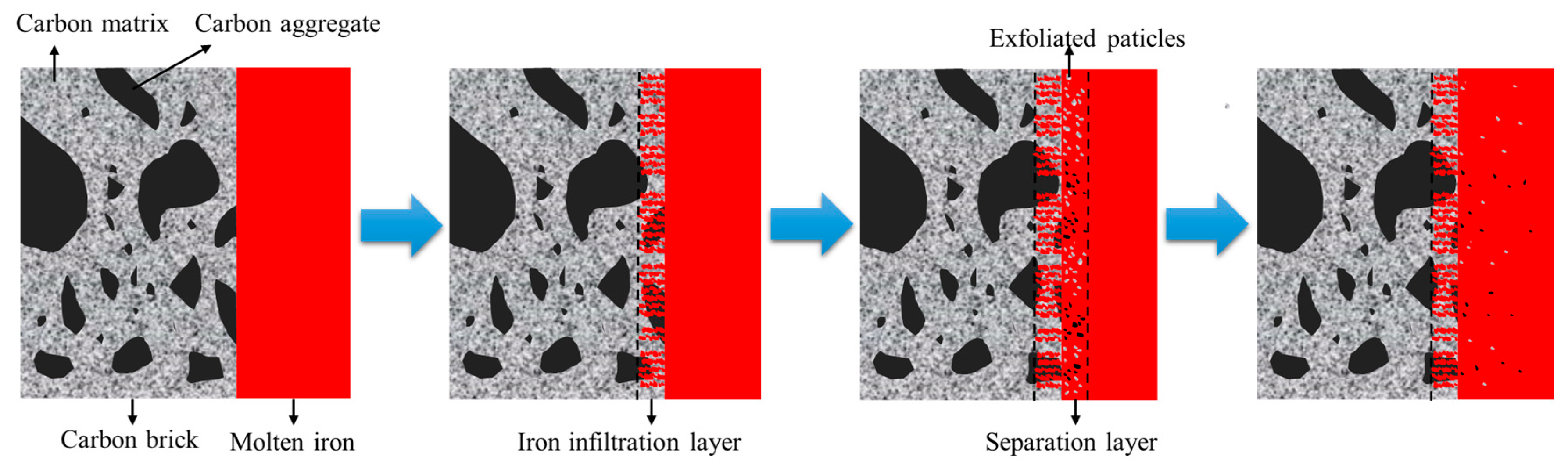
3.4.2. Corrosion Mechanism of Carbon Brick in Molten Iron

According to macroscopic and microscopic morphologies of carbon bricks before and after corrosion by molten iron, and thermodynamic analysis, the process of molten iron corroding carbon brick can be attributed to three aspects: the carburization, infiltration, and scouring of molten iron. The carburization process of molten iron has been demonstrated using the thermodynamic reaction analysis; its dissolution into molten iron can be further divided into three steps. The first step is the separation of carbon atoms from the solid carbon structure; the second step is the accumulation of the separated carbon atoms at the reaction interface; the third step is that the carbon atoms are adsorbed to the interstitial spaces of iron atoms from the reaction interface. In addition to the dissolution of the carbon into the molten iron, the infiltration of molten iron into carbon brick is another important cause of carbon brick corrosion. When molten iron penetrates the interior of the carbon brick, it will interact with the materials inside the carbon brick to form an iron infiltration layer, destroying the structure of the carbon brick at the iron–carbon interface, and then producing structural separation. The molten iron diffuses into the interior of the carbon brick through the pores and micro-cracks, and further deepens in combination with the carbon dissolution process. During the whole infiltration and carburization process, the channels that the molten iron diffused into from different paths may connect, resulting in local carbon brick to peel off from the main body to form a separation layer. Furthermore, the exfoliated particles will leave the separation layer for subsequent reaction behaviors. The scouring of molten iron, simulated by the stirring speed in the experiment, subjects the iron–carbon interface to interaction forces, which promotes the accelerated separation of the exfoliated fragmented carbon brick from the iron–carbon interface, thereby facilitating a new round of corrosion process as shown in Figure 16.
In the practical carbon brick production process, attention should be paid to the combination of carbon, Al2O3, SiO2, and SiC contents in carbon brick. Higher carbon and SiO2 contents will increase the corrosion by molten iron due to the reaction. Higher Al2O3 and SiC contents will hinder the contact between the carbon brick and the molten iron, delaying the corrosion of the carbon brick. The graphitization degree of carbon brick will also affect its corrosion; the higher of the graphitization degree, the lower of the corrosion degree. In addition, the microporous properties will also influence the corrosion of molten iron on carbon brick. Smaller average pore diameter and pore volume (<1 μm) contribute to a lower corrosion degree. Therefore, the formation of carbon nanotubes and SiC whiskers can also delay the corrosion of carbon brick while reducing the average pore diameter and retarding reaction. In terms of blast furnace operation, the temperature and composition of molten iron will affect the degree of dissolution of carbon in carbon brick into molten iron, that is, the greater the solubility of carbon in molten iron, the greater the degree of corrosion to carbon brick. Thus, the adjustment of temperature, content of each component, and activity interaction coefficient of this component and the carbon component for the reduction in carbon solubility in molten iron can weaken the dissolution of carbon in carbon brick into molten iron. In general, reducing the corrosion of molten iron on carbon brick is to reduce the carburization process of molten iron, the molten iron infiltration into carbon brick, and the scouring of molten iron to carbon brick.

4. Conclusions

The corrosion resistance to molten iron of four kinds of carbon bricks used in a blast furnace hearth were investigated to illustrate the corrosion mechanism through the macroscopic and microscopic analysis of carbon bricks before and after reaction and thermodynamic analysis. It was found that the corrosion resistance to molten iron of carbon brick could be improved by the combination of carbon, Al2O3, SiO2, and SiC contents in the carbon bricks, a high graphitization degree of carbon brick, a small average pore diameter and pore volume (<1 μm) of carbon brick, the formation of carbon nanotubes and SiC whiskers in carbon brick, a low solubility of carbon in molten iron, and the weakened scouring of molten iron to carbon brick, etc. The summarized specific consequences are as follows:
The chemical composition and phase analyses show that B has the highest carbon content, up to 84.13%, which is much greater than the other three types of carbon bricks. The main phases in A are C, Al2O3, SiC, and Al6Si2O13, the ones in B are C, Al2O3, and SiC, while the main phases of C and D are C, SiO2, and SiC. The analysis of physical and chemical properties shows that the resistance to molten iron infiltration of A is lower than that of the other three carbon bricks. The thermal conductivity of A and B is superior to C and D.
The macroscopic morphology analysis of carbon bricks after corrosion by molten iron shows that A has the lowest corrosion degree and highest uniformity at different heights, but a large number of holes are formed on the surface. The surface of B is smoother than A after corrosion, but the corrosion is severe at the gas–refractory–iron three-phase interface. C and D have irregular surfaces, their corrosion degree is between A and B, and there exists lighter corrosion characteristics of three-phase interface.
The microscopic morphology analysis of the original carbon bricks shows that A has obvious boundaries between the carbon matrix, white ceramic, and black carbon aggregates. Its internal surface is rough, with more micro-pores in the range of 20~70 μm. The ceramic in A carbon matrix is in dispersed distribution. There are some whiskers in the A pores. The boundary of the black carbon aggregate layer in B is not obvious, and the carbon matrix and ceramic are in dispersed and discontinuous distribution. Its surface is smooth, with fewer micro-pores; those that do appear are mostly in the size range of 20~50 μm. An obvious boundary is observed between the carbon aggregate and the non-aggregate in C, and cracks on its surface, but the micropores are relatively few, with long and thin features. The SiO2 and SiC ceramic phases are uniformly distributed in the carbon matrix, and no Al2O3 aggregation on the surface. A mass of flocculent whiskers exists in the pores of the original brick C, which are mainly determined to be SiC whiskers, and some carbon nanotubes exist in the pores of the carbon aggregates. D has denser and larger pores on the surface, with the size mainly ranging from 30 μm to 50 μm. A large number of whiskers are also found inside of the cracks, which are mainly inferred to carbon nanotubes, and part of SiC whiskers are mixed.
The microscopic morphology analysis of the carbon bricks after corrosion shows that all the carbon bricks have more and larger pores than their original carbon bricks. There exist pores on the internal interface of A with the diameter more than 100 μm, and the phenomenon of the iron beads adhering to the carbon brick mainly happens in the carbon aggregates. The mixed part of the carbon matrix and the ceramic phase is mainly iron infiltration. The surface of B is relatively flat after corrosion compared with that of A. There exist fewer iron beads adhering on the surface, most of which are iron infiltration with a thickness of nearly 50 μm. Many large cracks emerge on the surfaces of C and D with the length exceeding 1 mm in C and 2 mm in D. A large number of iron beads are bonded on the reaction interface of C, and the iron bead adhering to the reaction interface of D is not obvious. The iron penetration degree of C, D, and A is similar. C and D present an obvious corrosion process phenomenon, that is, the carbon matrix is broken and peeled off during the iron infiltration process. In addition, the whiskers inside the pores also tend to decrease as they approach the reaction interface.
The dissolution of carbon is the predominant reaction of the carbon brick being corroded. The higher the carbon solubility in molten iron, the easier it is to corrode the carbon brick. Al2O3 and SiC can enhance the corrosion resistance of carbon bricks to molten iron, and SiO2 can react with carbon to form pores, which will become channels for the penetration of molten iron and increase the corrosion of carbon bricks. A higher graphitization degree of carbon bricks is beneficial to lessen their corrosion degree.
The corrosion of carbon bricks by molten iron can be attributed to three aspects: the carburization, infiltration, and scouring of molten iron. The carburization process of molten iron is the main reaction process of molten iron corroding carbon brick. The infiltration of molten iron into carbon brick will facilitate the dissolution of carbon, destroying the structure of carbon bricks and accelerating the corrosion of carbon bricks. The scouring of molten iron subjects the iron–carbon interface to interaction forces, promoting the separation of the exfoliated fragmented carbon brick from the iron–carbon interface to facilitate a new round of corrosion process.

Author Contributions

Conceptualization, J.Z.; methodology, C.W. and K.J.; validation, W.C. and Z.L.; formal analysis, C.W.; investigation, Z.W. and T.W.; resources, X.L. and Z.P.; writing—original draft preparation, C.W. and Z.W.; and writing—review and editing, J.Z. and C.W. All authors have read and agreed to the published version of the manuscript.

Funding

This research was funded by the National Natural Science Foundation of China, grant number 51874025, and the Project of SKLAM, grant number 41622017 and K22-05.

Institutional Review Board Statement

Not applicable.

Informed Consent Statement

Not applicable.

Data Availability Statement

The data presented in this study are available on request from the corresponding author.

Acknowledgments

WISDRI Handan Wupeng New Lining Material Co., Ltd. is acknowledged for providing materials and collaborative research.

Conflicts of Interest

The authors declare no conflict of interest.

References

  1. Zhang, J.L.; Liu, Z.J.; Jiao, K.X.; Xu, R.S.; Li, K.J.; Wang, Z.Y.; Wang, C.; Wang, Y.Z.; Zhang, L. Progress of new technologies and fundamental theory about ironmaking. Chin. J. Eng. 2021, 43, 1630–1646. [Google Scholar]
  2. Liu, Z.J.; Zhang, J.L.; Zuo, H.B.; Yang, T.J. Recent progress on long service life design of Chinese blast furnace hearth. ISIJ Int. 2012, 52, 1713–1723. [Google Scholar] [CrossRef] [Green Version]
  3. Guo, Z.Y.; Zhang, J.L.; Jiao, K.X.; Gao, T.L.; Zhang, J. Research on low-carbon smelting technology of blast furnace-optimized design of blast furnace. Ironmak. Steelmak. 2021, 48, 685–692. [Google Scholar] [CrossRef]
  4. Zagaria, M.; Dimastromatteo, V.; Colla, V. Monitoring erosion and skull profile in blast furnace hearth. Ironmak. Steelmak. 2010, 37, 229–234. [Google Scholar] [CrossRef]
  5. Niu, Q.; Cheng, S.S.; Xu, W.X.; Niu, W.J. Microstructure and phase of carbon brick and protective layer of a 2800 m3 industrial blast furnace hearth. ISIJ Int. 2019, 59, 1776–1785. [Google Scholar] [CrossRef] [Green Version]
  6. Stec, J.; Smulski, R.; Nagy, S.; Szyszkiewicz-Warzecha, K.; Tomala, J.; Filipek, R. Permeability of carbon refractory materials used in a blast furnace hearth. Ceram. Int. 2021, 47, 16538–16546. [Google Scholar] [CrossRef]
  7. Ibrahim, S.H.; Skibinski, J.; Oliver, G.; Wejrzanowski, T. Microstructure effect on the permeability of the tape-cast open-porous materials. Mater. Des. 2019, 167, 107639. [Google Scholar] [CrossRef]
  8. Li, Y.W.; Chen, X.L.; Sang, S.B.; Li, Y.B.; Jin, S.L.; Zhao, L.; Ge, S. Microstructures and properties of carbon refractories for blast furnaces with SiO2 and Al additions. Metall. Mater. Trans. A 2010, 41, 2085–2092. [Google Scholar] [CrossRef]
  9. Ma, H.X.; Zhang, J.L.; Jiao, K.X.; Chang, Z.Y.; Wang, Y.J.; Zheng, P.C. Analysis of erosion characteristics and causes of blast furnace hearth. Iron Steel 2018, 53, 14–19. [Google Scholar]
  10. Liao, N.; Li, Y.W.; Jin, S.L.; Sang, S.B.; Harmuth, H. Enhanced mechanical performance of Al2O3-C refractories with nano carbon black and in-situ formed multi-walled carbon nanotubes (MWCNTs). J. Eur. Ceram. Soc. 2016, 36, 867–874. [Google Scholar] [CrossRef]
  11. Luo, M.; Li, Y.W.; Jin, S.L.; Sang, S.B.; Zhao, L.; Wang, Q.H.; Li, Y.B. Microstructure and mechanical properties of multi-walled carbon nanotubes containing Al2O3-C refractories with addition of polycarbosilane. Ceram. Int. 2013, 39, 4831–4838. [Google Scholar] [CrossRef]
  12. Mertke, A.; Aneziris, C.G. The influence of nanoparticles and functional metallic additions on the thermal shock resistance of carbon bonded alumina refractories. Ceram. Int. 2015, 41, 1541–1552. [Google Scholar] [CrossRef]
  13. Zhang, W.; Hua, F.B.; Dai, J.; Xue, Z.L.; Ma, G.J.; Li, C.Z. Isothermal kinetic mechanism of coke dissolving in hot metal. Metals 2019, 9, 470. [Google Scholar] [CrossRef] [Green Version]
  14. Jang, D.; Kim, Y.; Shin, M.; Lee, J. Kinetics of carbon dissolution of coke in molten iron. Metall. Mater. Trans. B 2012, 43B, 1308–1314. [Google Scholar] [CrossRef]
  15. Cham, S.T.; Sakurovs, R.; Sun, H.P.; Sahajwalla, V. Influence of temperature on carbon dissolution of cokes in molten iron. ISIJ Int. 2006, 46, 652–659. [Google Scholar] [CrossRef] [Green Version]
  16. Wright, J.K.; Baldock, B.R. Dissolution kinetics of particulate graphite injected into iron/carbon melts. Metall. Trans. B 1988, 19, 375–382. [Google Scholar] [CrossRef]
  17. Mourao, M.B.; Murthy Krishna, G.G.; Elliott, J.F. Experimental investigation of dissolution rates of carbonaceous materials in liquid iron-carbon melts. Metall. Trans. B 1993, 24B, 629–637. [Google Scholar] [CrossRef]
  18. Deng, Y.; Zhang, J.L.; Jiao, K.X. Dissolution mechanism of carbon brick into molten iron. ISIJ Int. 2018, 58, 815–822. [Google Scholar] [CrossRef] [Green Version]
  19. Deng, Y.; Liu, R.; Jiao, K.X.; Chen, Y.B. Wetting behavior and mechanism between hot metal and carbon brick. J. Eur. Ceram. Soc. 2021, 41, 5740–5749. [Google Scholar] [CrossRef]
  20. Deng, Y.; Liu, R.; Jiao, K.X.; Chen, L.D.; Chen, Y.B. Evolution and Mechanism of Dissolutive Wetting between Hot Metal and Carbon Brick. Available online: https://0-www-sciencedirect-com.brum.beds.ac.uk/science/article/pii/S0955221922002898 (accessed on 12 April 2022).
  21. Stec, J.; Tarasiuk, J.; Wro ´nski, S.; Kubica, P.; Tomala, J.; Filipek, R. Investigation of molten metal infiltration into micropore carbon refractory materials using X-ray computed tomography. Metals 2021, 14, 3148. [Google Scholar] [CrossRef]
  22. Jiao, K.X.; Fan, X.Y.; Zhang, J.L.; Wang, K.D.; Zhao, Y.A. Corrosion behavior of alumina-carbon composite brick in typical blast furnace slag and iron. Ceram. Int. 2018, 44, 19981–19988. [Google Scholar] [CrossRef]
  23. Wei, Y.W.; Shao, Y.; Chen, J.F.; Li, N. Influence of carbonaceous materials on the interactions among (Al2O3-C)/Fe system with temperature and soaking time. J. Eur. Ceram. Soc. 2017, 38, 313–322. [Google Scholar] [CrossRef]
  24. Wu, S.L.; Wang, X.L. Iron and Steel Metallurgy, 4th ed.; Metallurgical Industry Press: Beijing, China, 2019; pp. 146–216. [Google Scholar]
  25. Fan, X.Y.; Jiao, K.X.; Zhang, J.L.; Wang, K.D.; Chang, Z.Y. Phase transformation of cohesive zone in a water-quenched blast furnace. ISIJ Int. 2018, 58, 1775–1780. [Google Scholar] [CrossRef] [Green Version]
  26. Gupta, S.; Sahajwalla, V.; Chaubal, P.; Youmans, T. Carbon structure of coke at high temperatures and its influence on coke fines in blast furnace dust. Metall. Mater. Trans. B 2005, 36B, 385–394. [Google Scholar] [CrossRef]
  27. Warren, B.E. X-Ray diffraction in random layer lattices. Phys. Rev. 1941, 59, 693–698. [Google Scholar] [CrossRef]
  28. Arnold, T.; Chanaa, S.; Clarke, S.M.; Cook, R.E.; Larese, J.Z. Structure of an n-butane monolayer adsorbed on magnesium oxide (100). Phys. Rev. B Condens. Matter Mater. Phys. 2006, 74, 085421. [Google Scholar] [CrossRef]
  29. Lu, L.; Sahajwalla, V.; Kong, C.; Harris, D. Quantitative X-ray diffraction analysis and its application to various coals. Carbon 2001, 39, 1821–1833. [Google Scholar] [CrossRef]
  30. Klug, H.P.; Alexander, L.E. X-ray Diffraction Procedures: For Polycrystalline and Amorphous Materials, 2nd ed.; Wiley: New York, NY, USA, 1974; pp. 130–135. [Google Scholar]
  31. Xu, R.S.; Zhang, J.L.; Wang, W.; Zuo, H.B.; Xue, Z.L.; Song, M.M. Dissolution kinetics of solid fuels used in COREX gasifier and its influence factors. J. Iron Steel Res. Int. 2018, 25, 1–12. [Google Scholar] [CrossRef]
  32. Sun, M.M.; Zhang, J.L.; Li, K.J.; Li, H.T.; Wang, Z.M.; Jiang, C.H.; Ren, S.; Wang, L.; Zhang, H. The interfacial behavior between coke and liquid iron: A comparative study on the influence of coke pore, carbon structure and ash. JOM 2020, 72, 2174–2183. [Google Scholar] [CrossRef]
  33. Guo, Z.Y.; Jiao, K.X.; Zhang, J.L.; Ma, H.B.; Meng, S.; Wang, Z.Y.; Zhang, J.; Zong, Y.B. Graphitization and performance of deadman coke in a large dissected blast furnace. ACS Omega 2021, 39, 25430–25439. [Google Scholar] [CrossRef]
Figure 1. Carbon brick sample and matching ceramic rod.
Metals 12 00871 g001
Figure 2. Schematic diagram of the experimental apparatus.
Metals 12 00871 g002
Figure 3. XRD patterns of the four types of carbon bricks (AD are the types of carbon bricks).
Metals 12 00871 g003
Figure 4. Macroscopic morphology of carbon bricks before and after corrosion (AD are the types of carbon bricks).
Metals 12 00871 g004
Figure 5. Mass change rate, diameter change rate, and corrosion rate of the four carbon bricks after corrosion (A,B,C and D are the types of carbon bricks).
Metals 12 00871 g005
Figure 6. Schematic diagram of sample cutting before and after corrosion.
Metals 12 00871 g006
Figure 7. (ae) Microscopic morphology of the original brick A under different scaleplates.
Metals 12 00871 g007
Figure 8. (ae) Microscopic morphology of the original brick B under different scaleplates.
Metals 12 00871 g008
Figure 9. (ah) Microscopic morphology of the original brick C under different scaleplates.
Metals 12 00871 g009
Figure 10. (ae) Microscopic morphology of the original brick D under different scaleplates.
Metals 12 00871 g010
Figure 11. (ah) Microscopic morphology of A after corrosion.
Metals 12 00871 g011
Figure 12. (ad) Microscopic morphology of B after corrosion.
Metals 12 00871 g012
Figure 13. (ah) Microscopic morphology of C after corrosion.
Metals 12 00871 g013
Figure 14. (ah) Microscopic morphology of D after corrosion.
Metals 12 00871 g014
Figure 15. Variation of the standard Gibbs free energy of carburizing reactions with temperature.
Metals 12 00871 g015
Figure 16. Schematic diagram of the corrosion mechanism of carbon brick in molten iron.
Metals 12 00871 g016
Table 1. Chemical composition of the four types of carbon bricks.
Carbon BrickChemical Composition/%
CAl2O3SiO2SiCTiO2Others
A76.158.747.416.910.220.57
B84.134.436.763.230.331.12
C71.680.9114.3410.780.421.87
D79.541.3311.804.430.212.69
Table 2. Chemical composition of the molten iron sample.
Molten ironChemical Composition/%
FeCSiMnPS
95.873.500.300.150.150.03
Table 3. Physical and chemical properties of the four types of carbon bricks.
ItemUnitABCD
Apparent porosity%13.418.41112
Bulk densityg/cm31.811.691.761.72
Compressive strength (room temperature)MPa48.142.85048
Average pore diameterμm0.0340.080.050.1
Pore volume (<1 μm)%88.688.28678
Resistance to molten iron infiltration%18.721.42022
Gas permeabilitymDa0.390.710.83
Oxidation rate%0.821.6768
Thermal conductivity300 °CW/(m·K)29.1≥22≥1011
600 °C26.215.4≥1415
Table 4. Structural parameters of carbon bricks measured from the XRD spectra.
Carbon Brick2θ002d002/(nm)B002LC/(nm)NC
SGL26.480.340.28728.4485
NDK26.410.340.53215.3445
SM26.540.340.43118.9455
CM26.520.340.60113.5840
Publisher’s Note: MDPI stays neutral with regard to jurisdictional claims in published maps and institutional affiliations.

