
Innovative Tungsten Coatings for an Application in Modern and Future Fusion Devices


1
Institute for Physical Metallurgy and Materials Physics, RWTH Aachen University, 52056 Aachen, Germany
2
Institute of Energy and Climate Research (IEK), Forschungszentrum Jülich GmbH, 52428 Jülich, Germany
*
Author to whom correspondence should be addressed.
Metals 2023, 13(3), 531; https://0-doi-org.brum.beds.ac.uk/10.3390/met13030531
Submission received: 31 January 2023
/
Revised: 24 February 2023
/
Accepted: 2 March 2023
/
Published: 6 March 2023
(This article belongs to the Special Issue Tungsten and Tungsten Alloys)
Abstract
:Tungsten is foreseen presently as the plasma-facing material for divertors in fusion power plants. In order to achieve durable operation of divertors of current fusion reactors, an efficient way of maintaining the divertor functionality is needed. A system capable of in situ tungsten coating of the divertor via low-pressure plasma spraying was proposed to maintain the divertor integrity. In this work, tungsten was deposited on NB31 carbon fibre composite substrates using the low-pressure plasma spraying technology to evaluate the feasibility of this technique. The thickness, porosity, composition, adhesion, and microstructure of the coatings were investigated by scanning electron microscopy image analysis and energy dispersive spectroscopy. Based on the initial results, the spray parameters were iteratively improved in a campaign-based study. The coatings exhibited improving properties through an adjusting of the carrier gas flow, the scanning speed, and the spray distance. By lowering the carrier gas flow, the porosity of the coatings was reduced, resulting in coatings of 98% bulk density. Adjusting the carrier gas flow reduced the amount of semi-molten particles in the coatings significantly. A decrease in both scanning speed and spray distance increased the substrate’s temperature, which led to better adhesion and porosity.
1. Introduction
The conditions in fusion environments imply a complex composition of damaging mechanisms, which the plasma-facing components need to withstand. The heat, radiation, and tritium interaction are some of the most pressing issues; hence, various materials were considered for these components. Several fusion devices were equipped with carbon fiber composites (CFC) to face these challenges, since this material does not melt and exhibits good machinability and thermal conductivity. However, due to the high reactivity of CFC with hydrogen and the resulting safety risks these materials are mostly not considered for use in divertors anymore. Tungsten is favored nowadays as the material for plasma-facing components. In the scope of the ITER-like wall project at the Joint European Torus, for example, the CFC divertor was replaced with tungsten. That project took 18 months and large sums of money to realize, making the need for another method apparent [1].
A new method was proposed, that aims at coating the existing divertors with tungsten. This can be done in situ, for instance, utilizing the low-pressure plasma spraying (LPPS) technology. Coatings of 100 µm thickness were determined to be sufficient to withstand several experimental campaigns. Several coating methods were considered, with low-pressure plasma spraying being the most promising. For this, an LPPS system, attached to a robotic arm for in situ operations in a fusion device, is envisioned.
Some publications have already reported on applications of the LPPS technology to coat CFC with tungsten [2,3,4,5,6,7].
In this study, samples were first sprayed in the effort to qualify the coating process. Based on the findings of this work, further steps necessary to realize an in situ LPPS coating of plasma-facing components can be identified.
2. Materials and Methods
2.1. Materials
The 30 × 30 × 10 mm CFC slabs were coated with tungsten by applying the LPPS technology (Oerlikon Metco Multicoat) at the Jülich Thermal Spray Centre (JTSC) [8], using a F4-VB gun by Oerlikon-Metco. The CFC material used as substrate was the NB 31 manufactured by SNECMA Propulsion Solide. The feedstock for the coatings was the tungsten powder H.C. Starck Amperit 140.071, with particle sizes ranging from 5 µm to 25 µm.
The samples were made up of the CFC substrate with a tungsten coating deposited on the flat side.
2.2. Methods
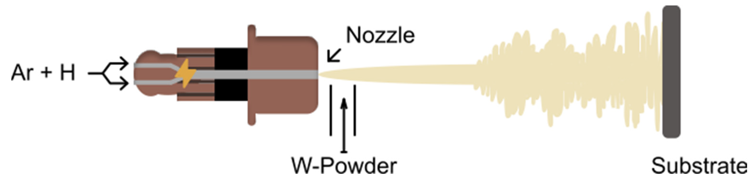
Plasma spraying technology is currently applied in a variety of fields. A schematic is provided in Figure 1. Its ability to rapidly build up coatings of materials with high melting points makes it a common choice for thermal barrier coatings. The LPPS technology used in this work conducts the spraying in an inert, low-pressure atmosphere. This is to eliminate gas interactions, such as the energy intensive dissociation of oxygen or the oxidation of the powder [9]. The coating properties are influenced by the particles’ behavior during the flight from the nozzle to the substrate and by their subsequent impact with the substrate. The particle characteristics can be modified by altering the spray parameters. In the scope of this work, the nozzle diameter, carrier gas flow, torch travel speed, and spray distance were varied. Table 1 shows the parameter combinations for each of the coated samples. The spray parameters that were not altered are listed in Table 2. The coatings were deposited within 3 campaigns: samples 1, 2, and 3 were sprayed within campaign 1; samples 4 and 5 within campaign 2; and samples 6 and 7 within campaign 3. Each campaign was designed with the aim of augmenting specific aspects of the coating properties.
The effects of these modifications on the coatings were investigated. The experiments were designed as an iterative parameter study, considering the findings of the previous campaigns. Three LPPS campaigns were conducted, each aiming at altering a specific aspect of the deposited coatings. Campaign 1 was designed based on preliminary studies; campaign 2 aimed at reducing the amount of overspray by adjusting the carrier gas flow; campaign 3 was carried out to further investigate trends found in campaigns 1 and 2 in order to reduce the porosity of the coatings by reducing the spray distance.
The samples were imaged by scanning electron microscopy (SEM), using the DSM 982 manufactured by Zeiss. Overspray, porosity, and thickness were measured by digital image analysis.
The coatings thickness, microstructures, porosity, and so-called overspray (insufficiently molten particles) were measured by planimetrics of SEM images. The porosity values were measured using the thresholding function of the ImageJ software package [10]. The applied algorithm was RenyiEntropy [11]. The number of pixels marked in that way was then divided by the total number of pixels in the image to calculate an area percentage. The porosity and overspray values given in this article are the area fractions measured in the specified manner. To extrapolate these 2D findings to the 3D materials, the principles of stereology were used, especially the first principle, which states that for sufficient data points, an average of an area fraction can be treated as an estimate of the average of the volume fraction [12].
The composition was analysed by energy dispersive X-ray spectroscopy (EDS), using the Oxford Instruments x-act facility. As EDS does not measure the composition of elements quantitatively, especially light ones, these results are to be used for qualitative statements only.
3. Results
3.1. Overspray
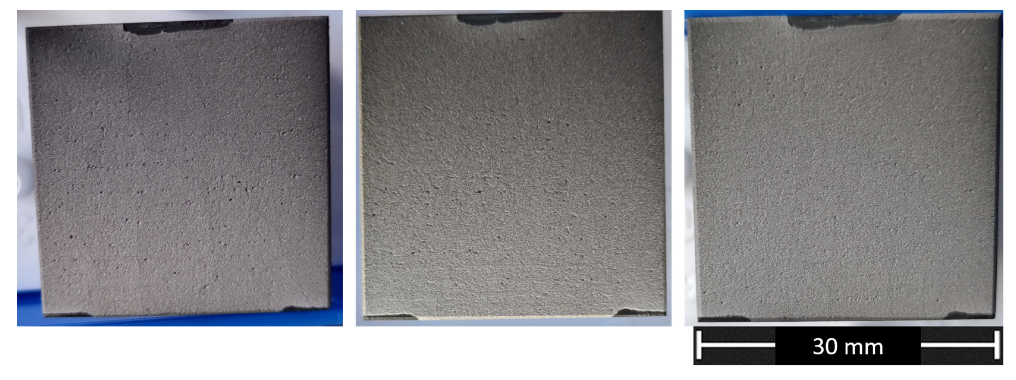
The amount of overspray found on the surface of the samples is shown in Table 3. For samples 1, 2, and 3, which were coated in campaign 1, a difference in overspray and color between the upper and the lower half of the sample was apparent (see Figure 2). These are referred to as dark and bright in Table 3. A significant reduction in overspray was noticeable for samples 4 and 5 compared to samples 1, 2, and 3. The adjustments applied for campaign 3 further reduced the fraction of overspray.
3.2. Porosity
Porosity is found mostly in between the splats, which make up the coatings. The volumetric porosities in the samples are shown in Table 4.
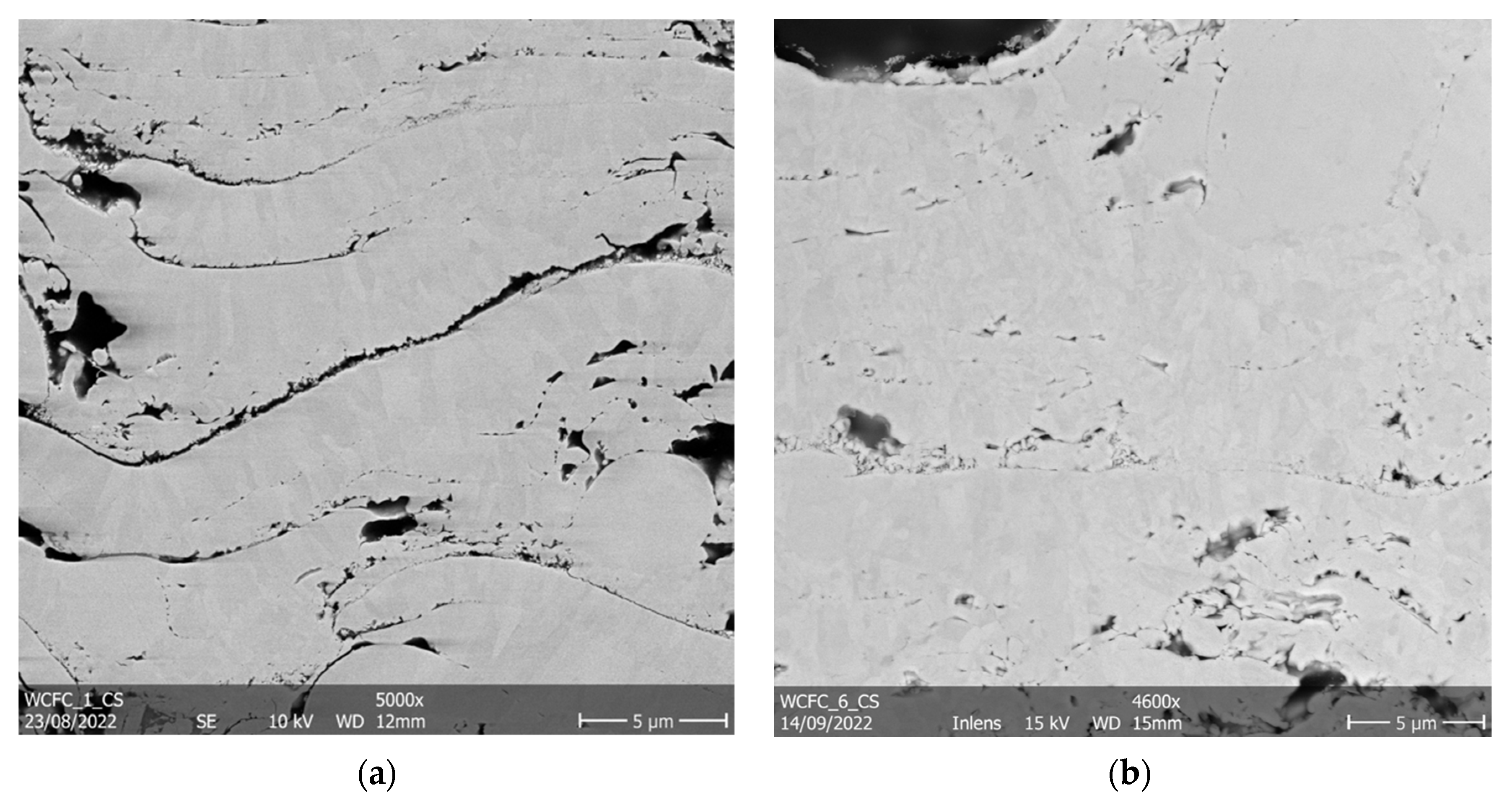
A constant reduction in porosity between the campaigns can be noticed. Voids are typically found between the splats, with negligible amounts of pores within the cores. This can be seen in Figure 3a,b.
3.3. Microstructure
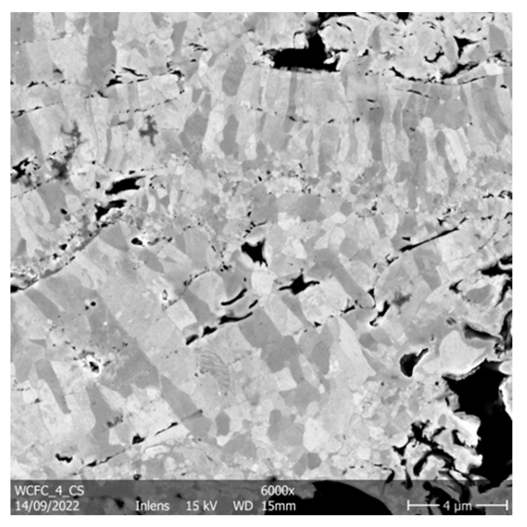
Typical grain structures for plasma-sprayed coatings were observed in all samples; an example is shown in Figure 4. The first solidified splats in each layer crystallize in finely dispersed, equiaxed grains. Such grains were also found in the vicinity of overspray particles. The remainder of each layer consists of columnar grains, which have their longitudinal axis in the growth direction of the coating. The finer grain sizes typically range from 0.1 µm to 1.5 µm. The columnar grains length was influenced by the layer thickness. The samples coated at a lower scanning speed therefore exhibited longer columnar grains compared to samples sprayed using a higher scanning speed. The columnar grains ranged from 0.6 µm to 4 µm in length in the longitudinal direction, while the shorter dimensions were similar in size to the equiaxed grains.
Some splats showed grains, which grew through the interface into a neighboring splat.
3.4. Composition and Impurity Content
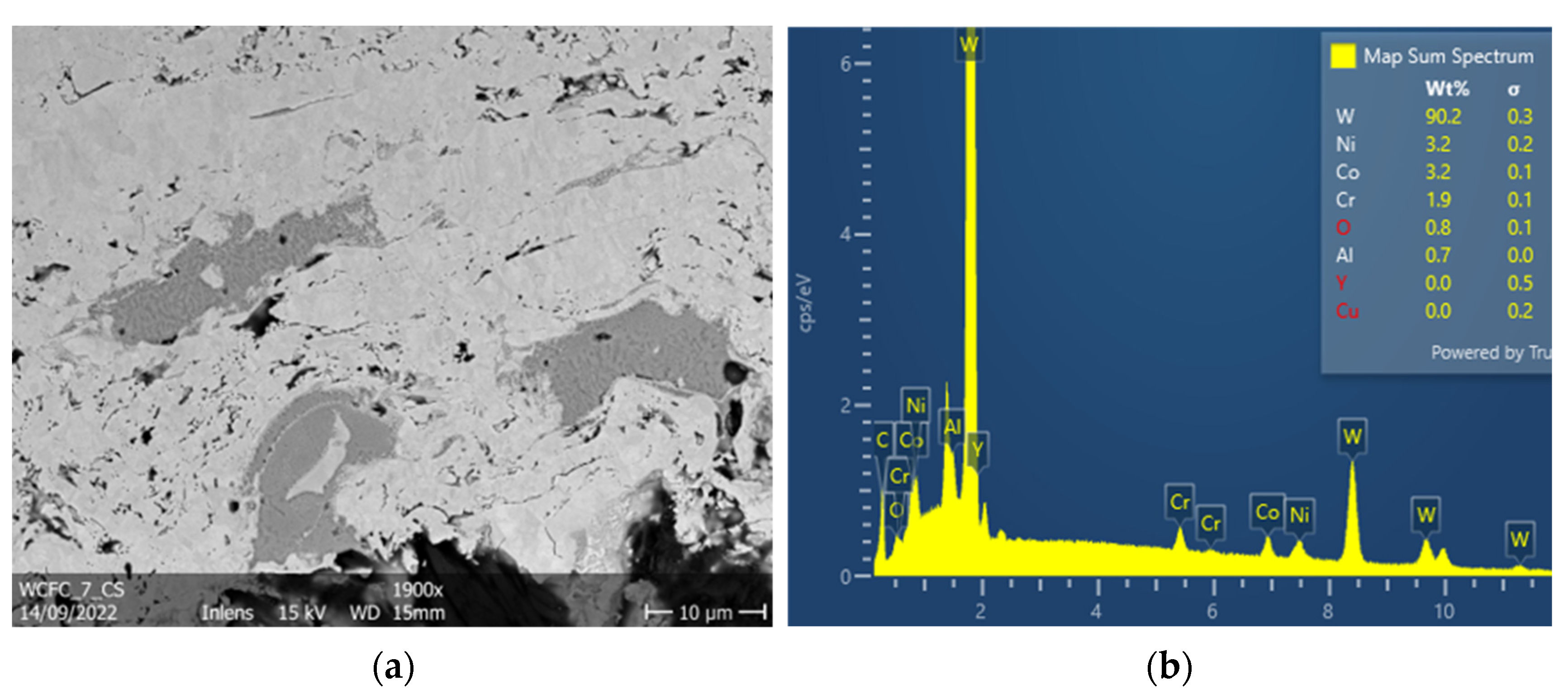
The elemental composition of the sprayed powder was investigated before spraying the samples by ICP OES. The results are shown in Table 5. The composition of the sprayed tungsten coatings was investigated by an EDS mapping of cross sections of the coatings. The majority of the coatings was found to be tungsten, with some oxygen signals found evenly distributed along the whole coating cross sections. No compositional difference was found between the matrix and the overspray particles. The oxygen content measured by EDS at 10 kV acceleration voltage was found to be consistently 10-fold higher than that measured in the tungsten feedstock powder by ICP OES.
Non-tungsten foreign phases were found in each coating, but in varying amounts. These inclusions always appear sharply delimited from the matrix. The matrix appears light grey, the inclusions dark grey in Figure 5. In all samples, a cobalt–nickel–chromium–aluminum alloy inclusion was found (Figure 5). Some other inclusions were also found, such as steel and nickel.
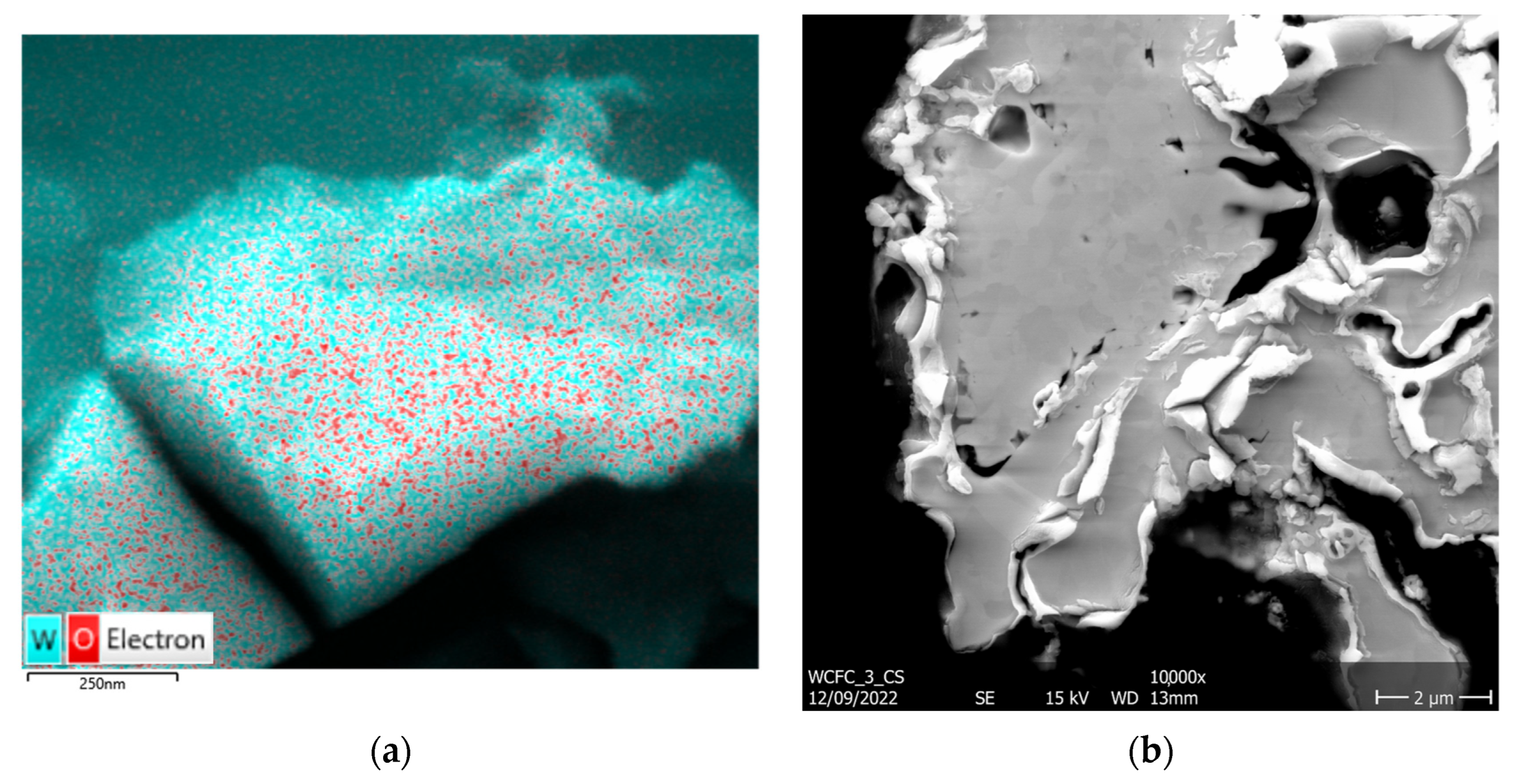
After several weeks exposing samples 1, 2, and 3 to air at room temperature, white matter was observed at the edges of the coatings (Figure 6b). The EDS mappings showed this matter to be tungsten oxides, as can be seen in Figure 6a.
Carbon was found in all EDS maps of the cross sections of the coatings. The carbon signals were concentrated exclusively within the pores.
3.5. Adhesion
The adhesion of the coatings to the substrates and the adhesion of the splats and layers to each other were only investigated visually. Inter-splat void networks can be seen clearly in between the splats in all samples. Across all samples, partial delamination of the coating from the substrate was observed.
3.6. Thickness
As stated before, a minimum thickness of 100 µm is deemed sufficient for withstanding several experimental campaigns. All coating thicknesses can be seen in Table 6.
4. Discussion
4.1. Overspray
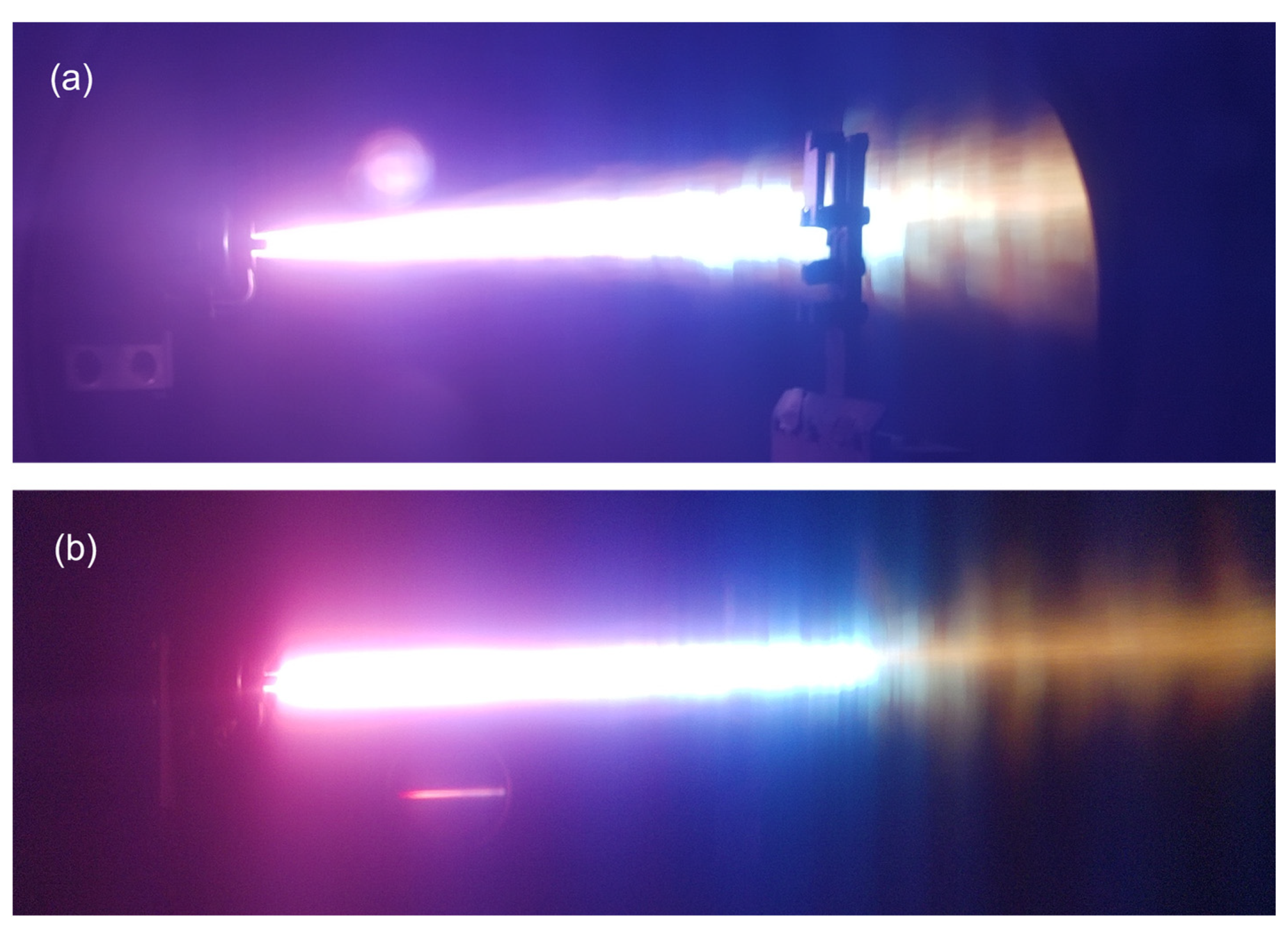
In [13], a correlation of delamination and cracking on the one hand, with overspray particles on the other hand, was found. This is due to the weak bonding between these particles and the rest of the coating. There are several potential reasons for the formation of overspray. All of them have in common that part of the powder injected into the plasma flame during LPPS leaves the plasma jet before impacting the substrate [13]. A shorter residence time of a particle within the jet leads to a lower amount of heat transferred to the particle, resulting in a lower fraction of fully molten particles reaching the substrate. As the color and amount of local overspray varied significantly across the surfaces of samples 1, 2, and 3 (see Figure 2; Table 3), an influence of the torch travel direction on the overspray was apparent. The influence of the carrier gas flow on the overspray was investigated in campaign 2. The carrier gas flow was adjusted from 1.3 slpm to 0.9 slpm for campaign 2, yielding a noticeable reduction in overspray. In Figure 7, the plasma flame and the powder trajectory are compared for campaign 1 (a) and campaigns 2 and 3 (b). The tungsten powder, which can be seen as the yellow glowing stream exiting the jet on the right, is concentrated around the plasma torch axis in Figure 7b. As the fraction of powder escaping from the jet before reaching the substrate was reduced, the fraction of unmolten particles in the deposited layers was reduced as well.
As sample 2 showed a lower fraction of overspray compared with samples 1 and 3, the nozzle diameter used in this experiment was also used for the other campaigns.
Lowering the spraying distance for samples 6 and 7 resulted in a further reduction of overspray, due to the smaller divergence of the particle plume.
4.2. Porosity
In previous studies [14,15,16,17,18], a correlation between the porosity of a plasma-sprayed coating and its thermal conductivity was suggested. The target porosity of 15% was reached for samples 1, 2, and 3, but further improvements seemed possible since sample 3 indicated a declining trend. It was coated at half of the torch travel speed while halving the number of layers. As most of the pores accumulate at the layer interfaces, a reduction in layers results in a reduction of the porosity because the interlayer porosity mainly results from deposited splats solidifying before any infiltration of the underlying surface is possible [19]. Increasing the temperature of the splats upon impact, as well as the surface temperature during coating, therefore results in lower interlayer porosity by decreasing the viscosity and increasing the solidification time. In our study, the slower scanning speed resulted in a longer residence time of the jet footprint on the sample surface and therefore a higher temperature of the splats upon solidification.
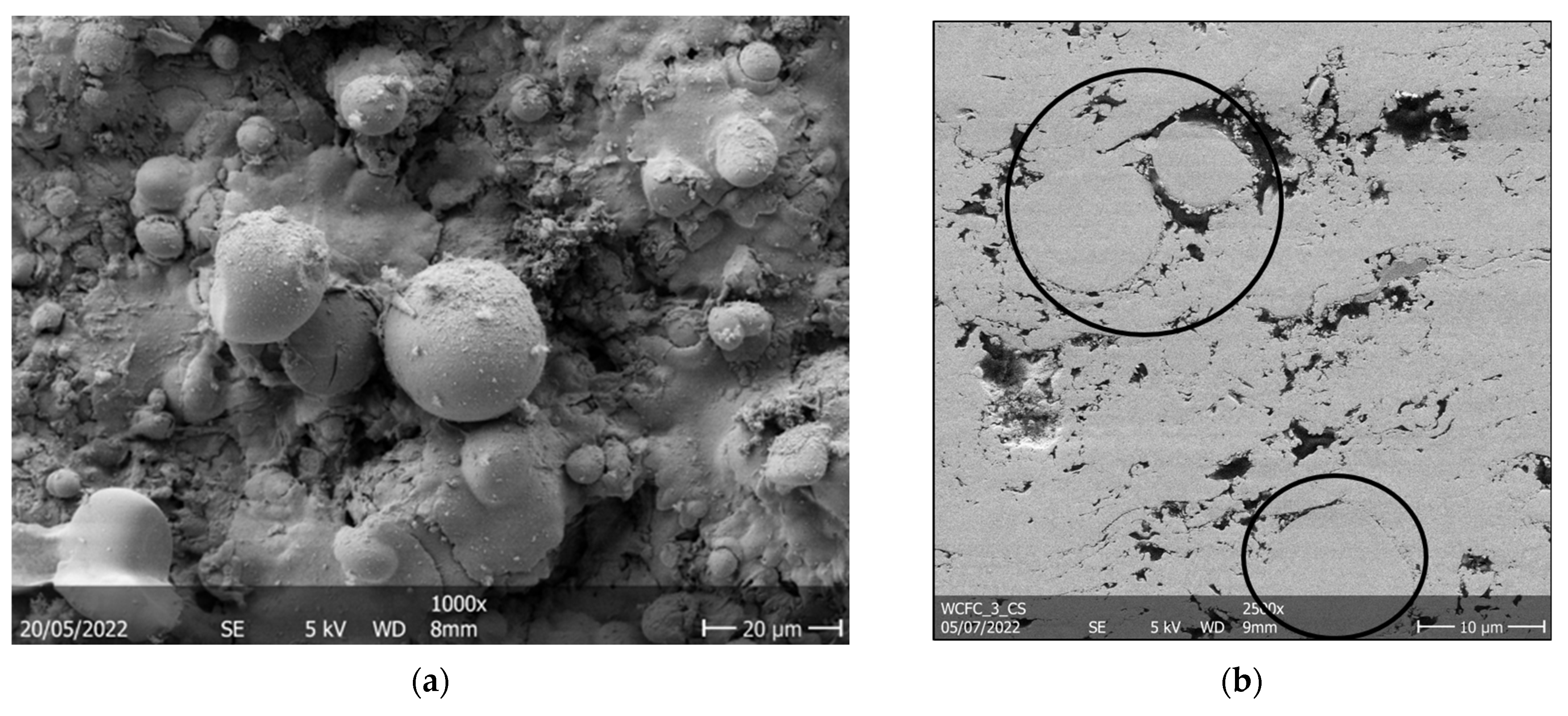
After improving the carrier gas flow prior to campaign 2, the porosity was reduced again. This can be explained by the reduction of overspray, since the unmolten particles are usually surrounded by pores, as can be seen in Figure 8b.
4.3. Composition
To analyse the purity of the tungsten coatings, EDS was applied. When investigating the cross section EDS maps, the majority of the detected signals were correlated to tungsten. Tungsten possesses a high oxygen affinity, as most refractory metals do. Thus, an increase in oxygen content was expected, even though an argon atmosphere at a pressure of 60 mbar was chosen to minimize atmospheric influence. In [20], a tungsten coating was sprayed in a vacuum atmosphere, but oxygen was found nonetheless.
Yttrium was found evenly distributed in the tungsten matrix. Only the yttrium Lα-line (1.922 keV) was measured. Due to the high quantities of tungsten found in the matrix, there are a lot of counts for its M-line (1.774 keV), resulting in some of them being attributed by the EDS system to yttrium’s Lα. There was no further indication for yttrium.
The foreign phase spots consisted mainly of a cobalt–nickel–chromium–aluminum alloy. Of these four metals, only traces of nickel were found in the powder feedstock (see Table 5). Therefore, these alloys have to originate from another source. The coatings previously sprayed on the same machine were so-called bond coats made up of CoNiCrAlY-alloy. Thus, these inclusions seem to have originated from bond coat deposits within the spray system. This is confirmed by the amount of inclusions being reduced for campaign 2 compared to campaign 1. This can be explained by the readjustment of the carrier gas flow before spraying these samples. This seems to have cleaned the machine of any residual bond coat powder before spraying the samples.
The carbon signals found in the samples can be attributed to the metallographic preparation. As mentioned previously, the carbon was observed exclusively in the pores. Therefore, it is assumed that during the grinding and polishing of the cross sections, graphite from the substrate was pulverized by the diamond paste and then carried onto the sample surfaces. As the top layers of the samples were continuously removed, this carbon was removed again, except within the pores. As these were the only instances of carbon found, tungsten carbides obviously were not formed during the coating process. Due to the envisioned system being specialized for in situ spraying of tungsten exclusively, these are issues which would not occur in the finished product.
The tungsten oxides found on the edges of samples 1, 2, and 3 after several weeks of exposure to air show that the investigated system oxidises at room temperature if exposed to air. This effect could have potentially detrimental impacts on its applicability to fusion environments.
4.4. Microstructure
From the microstructure, conclusions can be made on the solidification mechanisms. The lamellar structure, typical for plasma spraying [4,21], was observed in these coatings. During build-up of the coating, the impacting splats flatten and subsequently solidify [21,22]. This leads to the deposition of splats in layers, with each pass creating another layer. The inter-splat bonding has a strong impact on the thermomechanical properties of the coating [14,15,17,19,21,22], which in turn are dependent on the substrate and splat temperature during solidification.
Due to the large difference in temperature between the impinging liquid splat and the solid substrate, the liquid is supercooled. This leads to homogeneous solidification as a variety of grains grow rapidly in the supercooled liquid. This results in small, finely dispersed grains at the interfaces of the substrate or to a prior deposited pass. Grains in the later splats within a layer tend to grow longer and larger. This causes heterogenous grain growth, where the nucleation site is the underlying material. Because the heat is dissipated through the solid substrate, the grains requiring the least amount of energy to crystalize in the growth direction consume others [15,23]. An area with columnar grain structure can therefore be interpreted as being in good contact with the underlying material, and, vice versa, areas with finely dispersed, equiaxed grains usually have poor contact [24].
4.5. Adhesion
As stated before, the adhesion of the coating to the substrate and between layers govern the thermomechanical properties. As the primary objective of the coating is to dissipate the heat of the fusion plasma to the cooling system, adhesion is of great importance. If there is only poor adhesion in a specific area, the coating will overheat there due to low thermal conductivity [5]. Furthermore, delamination can lead to flaking off, which in turn impedes the plasma operation due to radiation [25] and further leaves that area unprotected.
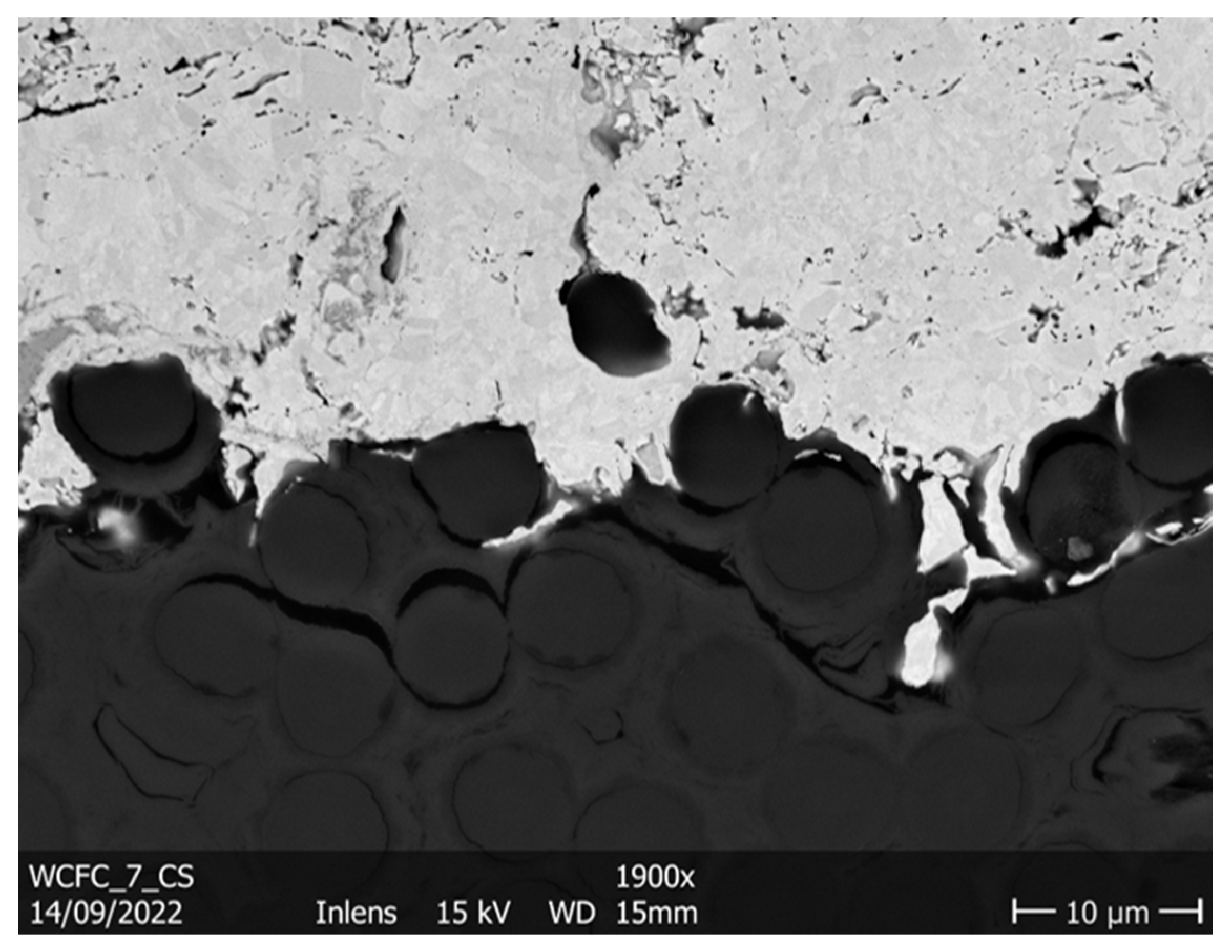
The adhesion of LPPS coatings is mainly a result of mechanical bonding. The adhesion is based on the liquid splats infiltrating the substrate, as can be seen in Figure 9. Additionally, during cooling, the metal contracts, which makes the deposit interlock with the surface roughness. Both these effects are strengthened as the substrate and particle temperature increase [14,15]. This is due to a lower viscosity of CFC leading to a deeper infiltration of the surface roughness before solidification. On the other hand, higher temperature differences lead to a larger thermal mismatch. In our study, tungsten infiltration of several µm of the substrate was found in all samples, for example, in Figure 9.
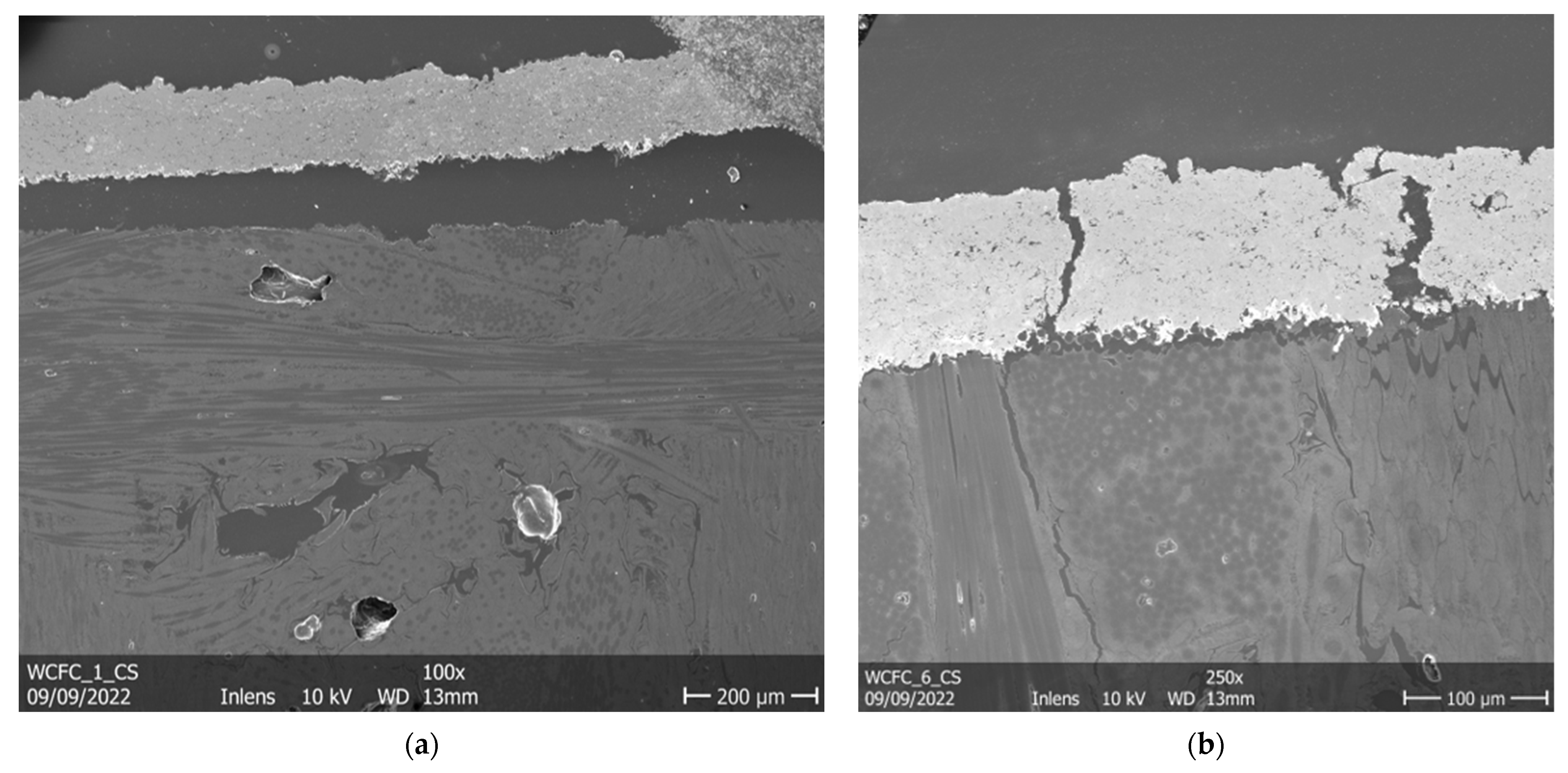
Delamination of the coating was mainly observed in the vicinity of cracks (Figure 10b) and at the edges of samples (Figure 10a). Such delaminations are assumed to be the result of thermal stresses induced during cooling. These stresses are partly caused by residuals from the cooling, but they also result from a difference in the thermal expansion rates of the substrate and the coating. The carbon fibre composite has a significantly lower thermal expansion coefficient compared to that of the tungsten coating. Tungsten has a thermal expansion coefficient of 4.6 × 10⁻⁶ K−1 at room temperature and 6.28 × 10⁻⁶ K−1 at 878 °C [26]. The CFC used is an anisotropic material, with different thermal expansion rates in different directions. A value of 0.5 × 10⁻⁶ K−1 was measured orthogonal to the interface surface [27]. Parallel to the interface surface, values of 1.2 × 10⁻⁶ K−1 in one direction and 2.7 × 10⁻⁶ K−1 in the other direction were recorded [27]. When cooling down, the difference in expansion rates leads to a compressive stress state on the surface of the coating and a tensile stress state at the substrate interface. To accommodate these stresses below the brittle-to-ductile transition temperature, the coating cracks make the coating spall off the substrate. At the edges, these stress states get relaxed by delamination without prior cracking. In our study, the substrate’s edges were ground down from sample 4 onwards, which led to a more favourable stress state and thus avoided the delamination at the edges of the coated samples.
In [5], a failure mode of plasma-sprayed tungsten on graphite CFCs during high heat flux tests was the inter-layer delamination. The interlayer porosity was steadily reduced between campaigns but never completely eliminated. These pore networks can still act as starting points for crack growth.
5. Conclusions
In this study, several tungsten coatings were manufactured by LPPS on CFC graphite substrates applying different coating parameters. An overall trend of improving the coatings properties by increasing the temperature during coating was established. In the scope of this work, the porosity of the coatings was reduced from 10.3% for the first sample coated to 3.5% for the seventh sample. Moreover, the amount of overspray was reduced significantly from 10.6% to 1.0%, improving the homogeneity of the microstructures. This was achieved by carrier gas flow optimization.
The coating composition was found to be mainly tungsten, with some inclusions which originated from the coating process. These inclusions should thus be eliminated by using a spray system, which exclusively sprays tungsten powders as envisioned for an in situ system in a nuclear fusion device.
Further improvements of the coating adhesion to the substrate are still needed. Even with the samples showing clear delamination in several spots, it was not possible to detach the coatings from the substrate. Even cutting the CFC base material close to the coating resulted in the rest of CFC remnants firmly attaching to the coating itself, thus showing strong adhesion between coating and substrate.
The optimization of this system can be achieved, based on the parameter set of sample 6. The evacuation of the LPPS chamber and tubes prior to coating deposition and a controlled cooling strategy will be a key part of that ongoing investigation.
An investigation into the thermal conductivity of sample 6 is currently underway.
To qualify the coatings for utilisation in a fusion power plant, the behavior under high heat fluxes of more than 10 MW/m2 needs to be investigated. Even with the coatings being bound to the substrate well, during operation the sample’s thermal expansion coefficient mismatch could lead to delamination, which needs to be investigated further. Finally, irradiation testing must be conducted.
If all qualifying coating tests are successful, a robotics system should then be designed to apply the coatings in situ inside a fusion reactor.
Author Contributions
Funding acquisition, A.L., C.L. and O.G.; investigation, T.K.; methodology, T.K., A.L. and G.M.; project administration, A.L. and G.M.; resources, A.L. and G.M.; supervision, A.L.; writing—original draft, T.K.; writing—review and editing, T.K., A.L., G.M., C.L. and O.G. All authors have read and agreed to the published version of the manuscript.
Funding
This work has been carried out within the framework of the EUROfusion Consortium, funded by the European Union via the Euratom Research and Training Programme (Grant Agreement No 101052200—EUROfusion). However, the views and opinions here expressed are those of the author(s) only and do not necessarily reflect those of the European Union or the European Commission. Neither the European Union nor the European Commission can be held responsible for them.
Data Availability Statement
All raw data are available on request from the author.
Acknowledgments
The authors would like to thank Marcin Rasinski and Leonardo Lealdini for assisting with the SEM and EDS, Ralf Laufs for his expertise in operating the spraying facilities, and the Zentralinstitut für Engineering, Elektronik und Analytik for the ICP OES analysis of the stockfeed powder.
Conflicts of Interest
The authors declare no conflict of interest.
References
- Matthews, G.F.; Beurskens, M.; Brezinsek, S.; Groth, M.; Joffrin, E.; Loving, A.; Kear, M.; Mayoral, M.-L.; Neu, R.; Prior, P.; et al. JET ITER-like wall—Overview and experimental programme. Phys. Scr. 2011, T145, 14001. [Google Scholar] [CrossRef]
- Tokunaga, K.; Yoshida, N.; Noda, N.; Kubota, Y.; Inagaki, S.; Sakamoto, R.; Sogabe, T.; Plöchl, L. Behavior of plasma-sprayed tungsten coatings on CFC and graphite under high heat load. J. Nucl. Mater. 1999, 266–269, 1224–1229. [Google Scholar] [CrossRef]
- Neu, R.; Maier, H.; Gauthier, E.; Greuner, H.; Hirai, T.; Hopf, C.; Likonen, J.; Maddaluno, G.; Matthews, G.F.; Mitteau, R.; et al. Investigation of tungsten coatings on graphite and CFC. Phys. Scr. 2007, T128, 150–156. [Google Scholar] [CrossRef]
- Kang, H.-K. Thermal properties of plasma-sprayed tungsten deposits. J. Nucl. Mater. 2004, 335, 1–4. [Google Scholar] [CrossRef]
- Hirai, T.; Bekris, N.; Coad, J.P.; Grisolia, C.; Linke, J.; Maier, H.; Matthews, G.F.; Philipps, V.; Wessel, E. Failure modes of vacuum plasma spray tungsten coating created on carbon fibre composites under thermal loads. J. Nucl. Mater. 2009, 392, 40–44. [Google Scholar] [CrossRef]
- Liu, X.; Yang, L.; Tamura, S.; Tokunaga, K.; Yoshida, N.; Noda, N.; Xu, Z. Thermal response of plasma sprayed tungsten coating to high heat flux. Fusion Eng. Des. 2004, 70, 341–349. [Google Scholar] [CrossRef]
- Tamura, S.; Liu, X.; Tokunaga, K.; Tsunekawa, Y.; Okumiya, M.; Noda, N.; Yoshida, N. High-temperature properties of joint interface of VPS-tungsten coated CFC. J. Nucl. Mater. 2004, 329–333, 711–716. [Google Scholar] [CrossRef]
- Vaßen, R. (Ed.) Jülich Thermal Spray Center-A New Research and Innovation Infrastructure of Forschungszentrum Jülich; Ceramic Forum International: Baden-Baden, Germany, 2020. [Google Scholar]
- Tejero-Martin, D.; Rezvani Rad, M.; McDonald, A.; Hussain, T. Beyond Traditional Coatings: A Review on Thermal-Sprayed Functional and Smart Coatings. J. Therm. Spray Technol. 2019, 28, 598–644. [Google Scholar] [CrossRef] [Green Version]
- Rasband, W.S. ImageJ; U.S. National Institutes of Health: Bethesda, MD, USA, 2011. Available online: http://imagej.nih.gov/ij (accessed on 29 January 2023).
- Renyi, A. (Ed.) On Measures of Entropy and Information, 1st ed.; Berkeley Symposium on Mathematical Statistics and Porbability: Berkeley, CA, USA, 1961. [Google Scholar]
- Russ, J.C.; Dehoff, R.T. Practical Stereology; Springer: Boston, MA, USA, 2000; ISBN 978-1-4613-5453-6. [Google Scholar]
- Guignard, A.; Mauer, G.; Vaßen, R.; Stöver, D. Deposition and Characteristics of Submicrometer-Structured Thermal Barrier Coatings by Suspension Plasma Spraying. J. Therm. Spray Technol. 2012, 21, 416–424. [Google Scholar] [CrossRef]
- Kovářík, O.; Haušild, P.; Siegl, J.; Chráska, T.; Matějíček, J.; Pala, Z.; Boulos, M. The influence of substrate temperature on properties of APS and VPS W coatings. Surf. Coat. Technol. 2015, 268, 7–14. [Google Scholar] [CrossRef]
- Matějíček, J.; Vilémová, M.; Nevrlá, B.; Kocmanová, L.; Veverka, J.; Halasová, M.; Hadraba, H. The influence of substrate temperature and spraying distance on the properties of plasma sprayed tungsten and steel coatings deposited in a shrouding chamber. Surf. Coat. Technol. 2017, 318, 217–223. [Google Scholar] [CrossRef]
- Fukuda, M.; Hasegawa, A.; Nogami, S. Thermal properties of pure tungsten and its alloys for fusion applications. Fusion Eng. Des. 2018, 132, 1–6. [Google Scholar] [CrossRef]
- Bolt, H.; Barabash, V.; Krauss, W.; Linke, J.; Neu, R.; Suzuki, S.; Yoshida, N.; Team, A.U. Materials for the plasma-facing components of fusion reactors. J. Nucl. Mater. 2004, 329–333, 66–73. [Google Scholar] [CrossRef] [Green Version]
- Boire-Lavigne, S.; Moreau, C.; Saint-Jacques, R.G. The relationship between the microstructure and thermal diffusivity of plasma-sprayed tungsten coatings. J. Therm. Spray Technol. 1995, 4, 261–267. [Google Scholar] [CrossRef]
- Fauchais, P. Understanding plasma spraying. J. Phys. D Appl. Phys. 2004, 37, R86–R108. [Google Scholar] [CrossRef]
- Greuner, H.; Bolt, H.; Böswirth, B.; Lindig, S.; Kühnlein, W.; Huber, T.; Sato, K.; Suzuki, S. Vacuum plasma-sprayed tungsten on EUROFER and 316L: Results of characterisation and thermal loading tests. Fusion Eng. Des. 2005, 75–79, 333–338. [Google Scholar] [CrossRef]
- Niu, Y.; Zheng, X.; Ji, H.; Qi, L.; Ding, C.; Chen, J.; Luo, G. Microstructure and thermal property of tungsten coatings prepared by vacuum plasma spraying technology. Fusion Eng. Des. 2010, 85, 1521–1526. [Google Scholar] [CrossRef]
- Shaw, L.L.; Goberman, D.; Ren, R.; Gell, M.; Jiang, S.; Wang, Y.; Xiao, T.; Strutt, P.R. The dependency of microstructure and properties of nanostructured coatings on plasma spray conditions. Surf. Coat. Technol. 2000, 130, 1–8. [Google Scholar] [CrossRef]
- Paradis, P.-F.; Ishikawa, T.; Yoda, S. Viscosity of liquid undercooled tungsten. J. Appl. Phys. 2005, 97, 106101. [Google Scholar] [CrossRef]
- Gottstein, G. Physical Foundations of Materials Science; Springer: Berlin/Heidelberg, Germany, 2004; ISBN 978-3-642-07271-0. [Google Scholar]
- Smirnov, R.D.; Krasheninnikov, S.I.; Pigarov, A.Y.; Rognlien, T.D. Tungsten dust impact on ITER-like plasma edge. Phys. Plasmas 2015, 22, 12506. [Google Scholar] [CrossRef]
- Dutta, B.N.; Dayal, B. Lattice Constants and Thermal Expansion of Palladium and Tungsten up to 878 °C by X-ray Method. Phys. Stat. Sol. (B) 1963, 3, 2253–2259. [Google Scholar] [CrossRef]
- Pintsuk, G.; Compan, J.; Linke, J.; Majerus, P.; Peacock, A.; Pitzer, D.; Rödig, M. Mechanical and thermo-physical characterization of the carbon fibre composite NB31. Phys. Scr. 2007, T128, 66–71. [Google Scholar] [CrossRef]
Figure 1.
Schematic of the plasma spray process.

Figure 2.
From left to right: sample 1, 2, and 3.

Figure 3.
SEM images of the cross sections of the coatings, in which the porosity and microstructure are clearly visible. (a) Inter splat voids observed in sample 1; (b) Cross section of sample 7 with reduced porosity.
Figure 3.
SEM images of the cross sections of the coatings, in which the porosity and microstructure are clearly visible. (a) Inter splat voids observed in sample 1; (b) Cross section of sample 7 with reduced porosity.

Figure 4.
Image of the cross sections, with clearly visible grain structures close to the substrate observed in sample 4.
Figure 4.
Image of the cross sections, with clearly visible grain structures close to the substrate observed in sample 4.

Figure 5.
(a) CoNiCrAl inclusions close to the CFC substrate of sample 7. Tungsten appears as light grey, inclusions as dark grey; (b) EDS map spectrum of Figure 5b. The dominant tungsten peak is accompanied by several Co, Ni, Cr, and Al peaks.
Figure 5.
(a) CoNiCrAl inclusions close to the CFC substrate of sample 7. Tungsten appears as light grey, inclusions as dark grey; (b) EDS map spectrum of Figure 5b. The dominant tungsten peak is accompanied by several Co, Ni, Cr, and Al peaks.

Figure 6.
(a) EDS map of a single particle. Tungsten is colored light blue; oxygen is colored red; (b) SEM image of a cross section of the oxidized interface area; the white matter is tungsten oxide at the tungsten–CFC interface.
Figure 6.
(a) EDS map of a single particle. Tungsten is colored light blue; oxygen is colored red; (b) SEM image of a cross section of the oxidized interface area; the white matter is tungsten oxide at the tungsten–CFC interface.

Figure 7.
Comparison of the plasma jet (a) before and (b) after adjustments of the carrier gas flow.
Figure 7.
Comparison of the plasma jet (a) before and (b) after adjustments of the carrier gas flow.

Figure 8.
(a) Overspray particles observed on the surface of sample 3; (b) overspray particles, marked by black circles, seen in the cross section of sample 3.
Figure 8.
(a) Overspray particles observed on the surface of sample 3; (b) overspray particles, marked by black circles, seen in the cross section of sample 3.

Figure 9.
Infiltration of a coating into the substrate’s surface, here observed in sample 7.

Figure 10.
Delamination close to the edge of sample 1 (a) and in the vicinity of surface cracks in sample 6 (b).
Figure 10.
Delamination close to the edge of sample 1 (a) and in the vicinity of surface cracks in sample 6 (b).


Table 1.
Spray parameters varied for the coating of samples.
| Campaign # * | Sample # * | Nozzle Diameter [mm] | Carrier Gas Flow [slpm **] | Scanning Speed [mm/s] | Spray Distance [mm] |
|---|---|---|---|---|---|
| 1 | 1 | 7 | 1.2 | 440 | 300 |
| 1 | 2 | 8 | 1.2 | 440 | 300 |
| 1 | 3 | 7 | 1.2 | 220 | 300 |
| 2 | 4 | 8 | 0.9 | 440 | 300 |
| 2 | 5 | 8 | 0.9 | 220 | 300 |
| 3 | 6 | 8 | 0.9 | 220 | 275 |
| 3 | 7 | 8 | 0.9 | 220 | 250 |
* Number; ** standard liters per minute.
Table 2.
Spray parameters.
| Parameter | Value |
|---|---|
| Plasma gas ratio | 3.48 (sl Ar)/(sl H) |
| Plasma gas flow rate | 51.5 slpm |
| Powder feed rate | 215 g/min |
| Process pressure | 60 mbar |
| Path offset | 4 mm |
| Torch power | 50 kW |
Table 3.
Overspray volume fraction of the samples.
| Campaign # * | Sample # * | Overspray [Vol-%] | |
|---|---|---|---|
| 1 | 1 | Bright side | 7.4 |
| Dark side | 10.6 | ||
| 2 | Bright side | 1.6 | |
| Dark side | 6.2 | ||
| 3 | Bright side | 4.7 | |
| Dark side | 10.4 | ||
| 2 | 4 | - | 2.3 |
| 5 | - | 2.2 | |
| 3 | 6 | - | 1.0 |
| 7 | - | 1.5 |
* Number.
Table 4.
Volumetric porosities.
| Sample # * | Porosity [vol-%] |
|---|---|
| 1 | 10.3 |
| 2 | 9.9 |
| 3 | 8.6 |
| 4 | 4.9 |
| 5 | 5.2 |
| 6 | 3.6 |
| 7 | 3.5 |
* Number.
Table 5.
Impurity content of the powder feedstock.
| Element | Weight Percent |
|---|---|
| Si | 0.1602 |
| Pb | 0.0071 |
| As | 0.0033 |
| Fe | 0.0062 |
| Ni | 0.0099 |
| Mo | 0.0034 |
| Cd | 0.0021 |
| O | 0.135 |
Table 6.
Average thickness of the coatings.
| Sample # * | Thickness [µm] |
|---|---|
| 1 | 133 |
| 2 | 117 |
| 3 | 102 |
| 4 | 101 |
| 5 | 112 |
| 6 | 114 |
| 7 | 122 |
* Number.
Disclaimer/Publisher’s Note: The statements, opinions and data contained in all publications are solely those of the individual author(s) and contributor(s) and not of MDPI and/or the editor(s). MDPI and/or the editor(s) disclaim responsibility for any injury to people or property resulting from any ideas, methods, instructions or products referred to in the content. |
© 2023 by the authors. Licensee MDPI, Basel, Switzerland. This article is an open access article distributed under the terms and conditions of the Creative Commons Attribution (CC BY) license (https://creativecommons.org/licenses/by/4.0/).
Share and Cite
MDPI and ACS Style
Keller, T.; Litnovsky, A.; Mauer, G.; Linsmeier, C.; Guillon, O. Innovative Tungsten Coatings for an Application in Modern and Future Fusion Devices. Metals 2023, 13, 531. https://0-doi-org.brum.beds.ac.uk/10.3390/met13030531
AMA Style
Keller T, Litnovsky A, Mauer G, Linsmeier C, Guillon O. Innovative Tungsten Coatings for an Application in Modern and Future Fusion Devices. Metals. 2023; 13(3):531. https://0-doi-org.brum.beds.ac.uk/10.3390/met13030531
Chicago/Turabian StyleKeller, Tom, Andrey Litnovsky, Georg Mauer, Christian Linsmeier, and Olivier Guillon. 2023. "Innovative Tungsten Coatings for an Application in Modern and Future Fusion Devices" Metals 13, no. 3: 531. https://0-doi-org.brum.beds.ac.uk/10.3390/met13030531
Note that from the first issue of 2016, this journal uses article numbers instead of page numbers. See further details here.