
Asymmetric Shape Control Ability and Mutual Influence of the S6-High Cold Rolling Mill
National Engineering Technology Research Center of Flat Rolling Equipment, University of Science and Technology Beijing, Beijing 100083, China
*
Author to whom correspondence should be addressed.
Metals 2024, 14(5), 507; https://0-doi-org.brum.beds.ac.uk/10.3390/met14050507
Submission received: 19 March 2024
/
Revised: 16 April 2024
/
Accepted: 18 April 2024
/
Published: 26 April 2024
(This article belongs to the Section Metal Casting, Forming and Heat Treatment)
Abstract
:The control of the asymmetric shape of strips has always been an important and difficult part of the production of cold rolling strips. In this paper, the S6-High cold rolling mill is taken as the research object. A finite element model of this mill is constructed using ABAQUS 2022 software, and a multistage working condition simulation analysis is carried out. The independent effects of asymmetric Intermediate Roll Bending (IRB) and asymmetric Intermediate Roll Shifting (IRS) on the strip shape are investigated by constructing an asymmetric convexity evaluation index. The equivalent relationship between the asymmetric roll bending and the asymmetric roll shifting was determined by analysing the coupling effect of the benchmark bending and shifting rollers on their asymmetric shape control characteristics. The on-site application shows that optimizing the amount of preset asymmetric shape control can significantly improve the asymmetric situation of the shape, providing theoretical guidance for the asymmetric shape control of the S6-High cold rolling mill.
1. Introduction
Multiroll mills with small working roll diameters and a high thinning capability have emerged as the primary equipment for producing thinner, stronger, and flatter strips in the cold rolling process. The S6-High cold rolling mill, the focus of this article, serves as the key apparatus for manufacturing high-strength steel. Similar to the 6-High cold rolling mill, it incorporates the Intermediate Roll Bending (IRB) and Intermediate Roll Shifting (IRS) methods for strip flatness control [1,2,3]. Nevertheless, during production, the issue of asymmetric strip flatness frequently arises due to variations in input material performance and inadequate dimensional accuracy of the mill, which cannot be effectively resolved using conventional symmetric control. This problem significantly compromises the quality of the strip product and, in severe cases, can lead to runout and strip breakage, causing irreparable damage to the mill. Consequently, achieving asymmetric flatness control has become a major concern for S6-High mills, prompting the development of a range of effective asymmetric strip shape control strategies [4,5].
Multiroll mills can be divided into tower roll systems and composite roll structures according to the roll system arrangement, and the representative models are twenty-roll mills and eighteen-roll mills [6]. The current research on multiroll mills is becoming increasingly in-depth as production needs increase. Valigi M. C. et al. [7] studied the “chatter” of strip steel during rolling by analysing the characteristics of an eighteen-roll mill using vibration analysis. Wu et al. [8] constructed a dynamics simulation model for the longitudinal and transverse coupling of a twenty-roller mill by modelling the rolling force fluctuations. Wang et al. [9] calculated the interroll contact stresses and combined forces in the static process and in the rolling condition by analysing the assembly angle of the roll system of a twenty-roll mill. Zhou et al. [10] used ABAQUS 2022 software to construct a finite element model of a 20-roll mill and investigated the combined regulation characteristics of segmental press down and intermediate roll tampering roll down. The existing multiroll mill rolling process research is mainly focused on mill vibration and finite element analysis and mainly focuses on 20-roll mills, while 18-roll mills are less studied. As a representative model of the composite roll system, the S6-High mill, as one of the 18-roll mills, inherits the linear roll system arrangement of the four and six roll mills and uses the side support roll system to press against the working rolls to reduce the deflection of the small-diameter working rolls, so it is widely used in the rolling process of high-strength steel and stainless steel.
Research on the control of complex strip shapes such as asymmetric shapes has become increasingly mature, and its control mainly relies on asymmetric control means, such as roll tilting, asymmetric roll bending, asymmetric roll shifting, and online dynamic roll adjustment techniques. Zhang et al. [11] used finite element simulation to construct a finite element model of a six-roller mill and investigate the effect of asymmetric shape regulation mechanisms such as intermediate bending rolls and intermediate shifting rolls on the section shape and proposed an asymmetric shape control strategy. Yan et al. [12] used a hybrid particle swarm algorithm to simulate the thickness distribution in the rolling process and analysed the effect of asymmetric working roll bending on the strip section profile. Wang et al. [13] analysed the efficiency factor matrix of the roll tilting actuator in a UCM mill and established a self-learning model of the actuator efficiency coefficient. Prinz et al. [14] developed a feedforward automatic thickness control system to compensate for the asymmetry of the cross-sectional profile during hot rolling. Alvarez et al. [15] constructed a monitoring system to detect and correct uneven thickness on both sides during the hot rolling process. The current research on asymmetric shape control focuses on four-high mills used in hot rolling and six-high mills used in cold rolling processes, and the equivalent and mutual effects of bending and tilting rolls have not been fully accounted for. At the same time, while the tower roll system in an S6-High mill with a small working roll diameter of the multiroller mill has a certain effect on improving the roll deflection, due to its own susceptibility to high levels of secondary deflection, research on controlling the asymmetric plate shape in an eighteen-roller mill still needs to be further expanded.
This study focuses on improving the asymmetric shape control of a 1450 mm S6-High cold rolling mill through the use of asymmetric IRB (Intermediate Roll Bend) and IRS (Intermediate Roll shifting). A finite element simulation was constructed using ABAQUS 2022 software to assess the effectiveness of the asymmetric control methods and to study the interaction and equivalence of the bending and shifting rolls. The results showed that optimizing the preset asymmetric shape control parameters significantly improved the strip’s asymmetry, reducing material wastage and improving product quality and efficiency.
2. Finite Element Modelling and Validation
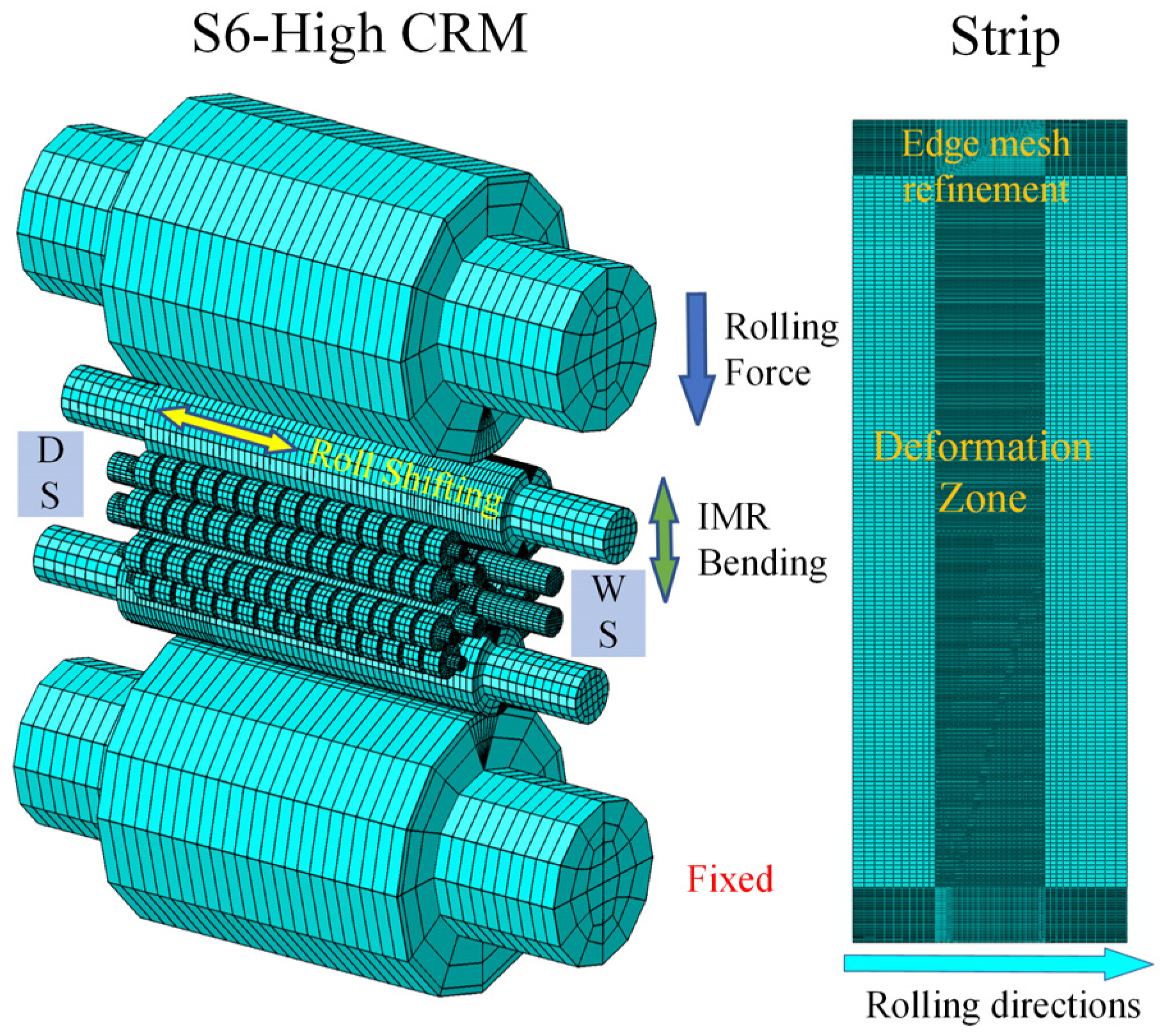
To clearly analyse the strip deformation behaviour under asymmetric control, this paper constructs a static implicit finite element model of a 1450 S6-High mill based on ABAQUS 2022 software. The model contains seven components: a back-up roll, intermediate roll, work roll, side support roll, back-up bearing roll, a core shaft, and a strip. The rolls and back-up bearing roll are elastomeric, and the strip is constructed using an elastoplastic model [16]. Since the side support roll system is assembled in a separate frame, the core shaft is set as a rigid body. The parameters of the roller system are given in Table 1. To improve the accuracy of the finite element calculation, the positions of the contact zone between the rolls and the contact zone between the rolls and the strip have been refined. For load application, the rolling force is applied in the same way as in the real world, and the rolling simulation is performed by pressing down. For the application of bending roll forces, the effect of asymmetric bending rolls is considered. Therefore, four positions, WS (work side), DS (drive side), the upper roll system, and the lower roll system, are applied separately. The IRS are assembled according to a fixed spatial relationship between their positions. The model as a whole is shown in Figure 1.
The movement of the model is divided into several steps: pressing down, applying bending rolls and tension, and rotating the roll. The main purpose of the model is to simulate the real rolling process of pressing down, building tension, and rolling after threading. The strip after the rotary rolling is taken as the research position. The specific rolling parameters of the model are shown in Table 2, where taper coverage refers to the size of the tapered part of the roll covering the edge of the strip during the intermediate roll shifting. The rolled steel grade is 65 Mn with a more prominent asymmetric shape problem.
Simulation and validation of the model: In this paper, the accuracy of the model was verified by means of two verification modes: strip thickness reduction and side support roll pressure. For the actual production requirements, the required thickness reduction tolerance is usually within 10 μm. The actual thickness reduction was 0.579 mm, and the model simulation result was 0.571 mm, showing an error of 1.4%.
The same needed to be verified for the side support roll system, which is unique to the S6-High mill. Firstly, we constructed the numerical force model of the S6-High rolling mill roll system, as shown in Figure 2.
Through calculations, the coordinates of the work roll positions for the S6-High rolling mill can be determined as shown in Equations (1) and (2) due to the control mechanisms.
where and is the centre position of the work roll; is the radius of the work roll in millimetres; is the radius of the side support roll in millimetres; h is the thickness of the strip at the exit in millimetres; and is the angle between the side support axis and the horizontal in degrees.
Simultaneously, based on the overall force balance of the roll system and the local force balance of the work roll, the force exerted on the side support can be calculated as shown in Equation (3).
where represents the rolling pressure, kN; is the exit tension, kN; is the entry tension, kN; denotes the work roll shifting angle; is the angle between the line connecting the radius of friction circle between the intermediate roll and the work roll (N1) and the vertical; represents the angle between the rolling support reaction force and the perpendicular line; is the angle between the line connecting the centre of the work roll and the centre of the side support roll and the horizontal line; and is the angle between the line connecting the radius of friction circle between the side support roll and the work roll (N2) and the horizontal.
In the actual production, the force of the side support roll is 223 kN, the finite element simulation result is 207 kN, and the numerical simulation result is 214 kN. The finite element simulation’s error is 7.2%. This indicates that the model can effectively represent the unique work roll shifting of the S6-High rolling mill during the rolling process. It is capable of studying the variation in the effectiveness of asymmetric control power with actual strip shape control parameters. The model’s accuracy meets the requirements of the simulation.
3. Evaluation of Asymmetric Shape
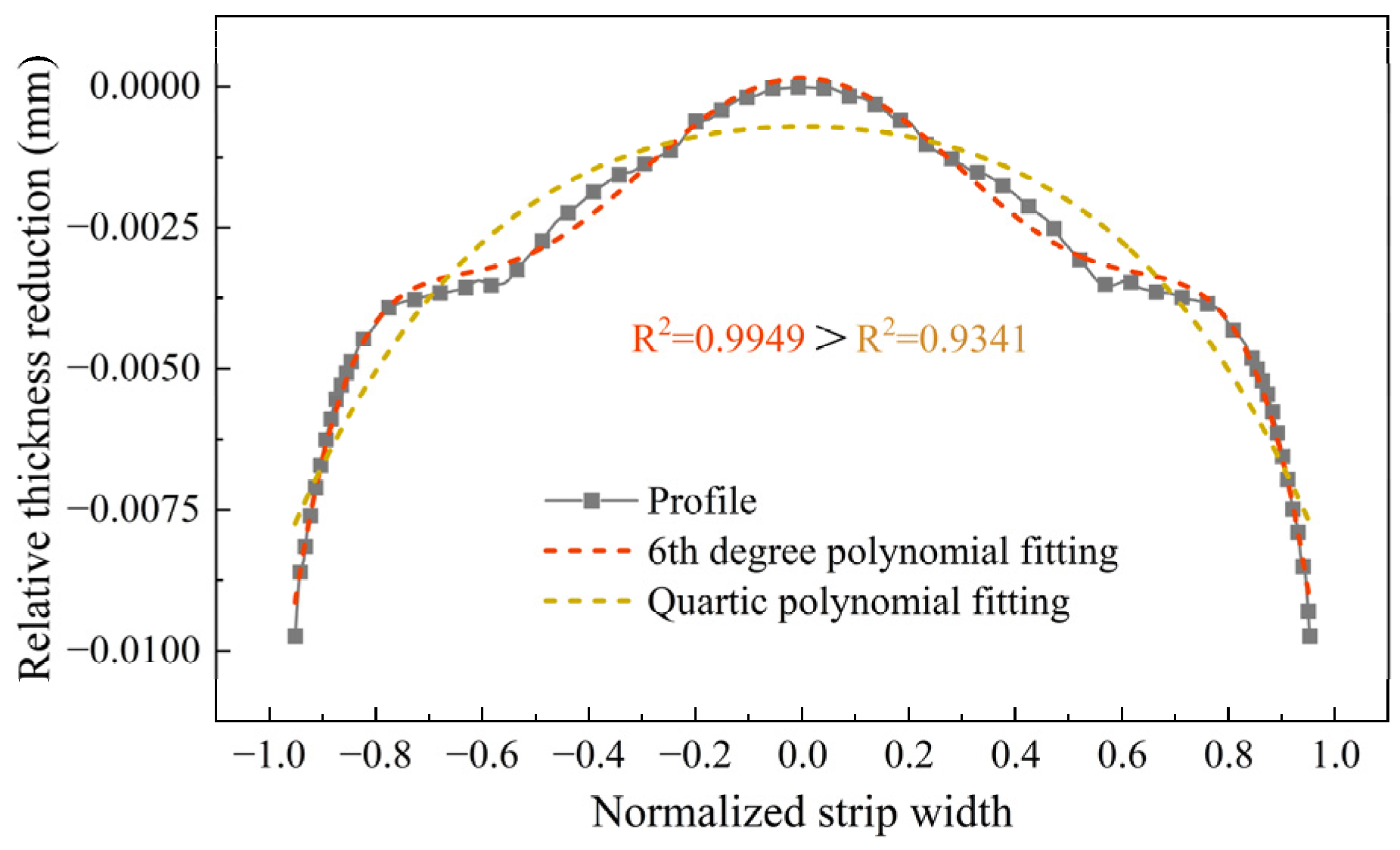
Asymmetric flatness control methods can achieve nonuniform control of the cross-sectional shape by changing the shape of the roll gap. To quantify the effect of an asymmetric bending roll on the strip shape, Chebyshev polynomials were applied to achieve a separation of the various order components of the shape fit. The width was normalized to [4,5], where the direction corresponds to the DS and the direction corresponds to the WS. Additionally, the small working roll diameter of the S6-High mill makes it susceptible to high-order deflection. Therefore, the effects of fourth-order fitting and sixth-order fitting were separately compared for a given operating condition, as shown in Figure 3.
It is more evident from the above figure that the degree of fit of the shape is much higher for the six-fit than for the four-fit, so the specific fitting formula is determined as shown in Equation (4) [17].
where x is the normalized strip width, is a constant term, and are the Chebyshev polynomial primary, quadratic, quadratic, and hexadratic coefficients, respectively, representing the components of each order of the fitted section shape.
For Cw1 in this fit, the trend in its variation can be obtained directly by fitting the full width of the section’s shape, while in actual production, it can be compensated for by roll tilt control. However, for an even number of components in the fitting process, it is difficult to assess the shape asymmetry, so the mirroring method is used. The actual shape on the DS is mirrored to the WS for fitting, the actual shape on the WS is mirrored to the DS for fitting, and the asymmetry of the strip can be found from the difference between the two fits. The calculation method is shown in Figure 4, and the even-order asymmetric convexity term is calculated as shown in Equation (5).
where is the asymmetric convexity, is the WS postmirror convexity, is the DS postmirror convexity, and n is the order of fit.
4. Control Effect of Asymmetric IRB and IRS
Asymmetrical IRB and asymmetrical IRS are important means of regulating the uniformity of the strip section’s profile [18]. By applying the control variable method to analyse the independent effects of these two means, the trends in the strip section’s profile can be more clearly characterized.
4.1. Control Effect of Asymmetric IRB
The IRB is an important means of improving the strip shape, which can be controlled by changing the roll deflection. The shape of the strip is inseparable from the profile of the strip after it has been rolled, so analysing the shape trend under different bending roll forces is a useful way of characterizing their controllability [19]. The IRB of an S6-High cold rolling mill is applied in such a way that the bending roll force is applied to the same side of the intermediate roll by means of a hydraulic cylinder. Therefore, although the intermediate roll shape in the assembly is anti-symmetric up and down when asymmetric bending rolls are applied to the WS and DS, respectively, this is not the case for the roll shape asymmetric as the standard that is usually applied.
In this paper, the WS bending roll force is the base bending roll force, and the base intermediate roll tampering roll coverage is 100 mm. The working condition is set by changing the bending roll force. Because the limit value of bending roller force is −200~300 kN, at the same time, to ensure the existence of a difference in the bending roller force on both sides, the benchmark bending roller force will be 100 kN, the range will be −100~200 kN, and the range of the bending roller force difference on both sides will be determined as being between −100 and 100 kN; the calculation formula can be seen in Equation (6), and the specific working conditions are shown in Table 3.
where is the difference in IRB between the two sides, is the IRB of the WS, and is the IRB of the DS.
The above working conditions were simulated, and the shape of the rolled section shape is shown in Figure 5.
As seen from the above figure, with the application of the asymmetric IRB, the section profile of the strip also clearly shows a higher level of asymmetry. As the WS IRB is selected as the reference point, the variation in the DS section profile per unit of bending roll force is significantly greater than that of the WS, while the difference between the WS thickness reduction and the DS thickness reduction under different asymmetric bending roll forces shows a trend of decreasing and then increasing with the 0 kN bending roll force as the reference point. At a reference point of −100 kN, the direction is the same as the direction of the applied rolling force. When the reference is 100 kN, the bending roll force is equivalent to the resistance to deflection caused by the rolling force, so the difference between the two sides is more obvious at negative values. However, at a base bending roll force of 200 kN, the change in the thickness reduction on the WS is reduced to almost zero as the ratio of the asymmetric bending roll force to the base bending roll force decreases.
Two of the paired bending rolls with equal summed forces were selected for comparison, as shown in Figure 6. In the case of equal total bending roll forces, the shape is perfectly symmetrical between the WS and DS after symmetrical increase and decrease, and the change in the total bending roll force value only changes the overall convexity of the section profile and does not change the asymmetry of the WS and DS.
There is a clear difference in the asymmetric regulation efficacy under the action of different reference bending roll forces. To more accurately show the effect of asymmetric bending roll forces on the strip section profile, the asymmetric bending roll convexity regulation efficacy under different operating conditions can be defined as shown in Equation (7) [20]. The results are shown in Figure 7.
As shown in the above graph, asymmetric bending rolls have a noticeable adjustment effect on both primary convexity and secondary asymmetric convexity. The overall distribution is essentially linear, and the values do not exhibit significant deviation from each other. Simultaneously, the asymmetric control capacity of the unit’s asymmetric bending roll gradually declines with an increase in the reference intermediate roll bending force, which is attributed to the gradual decrease in the ratio of the asymmetric bending roll force to the reference bending roll force. With regard to the four-times asymmetric convexity and six-times asymmetric convexity, the adjustment efficiency presents a strongly nonlinear distribution with an increase in the reference bending roll force, which is difficult to describe through specific indicators but is approximately of and , with the application effect being negligible.
4.2. Control Effect of Asymmetric IRS
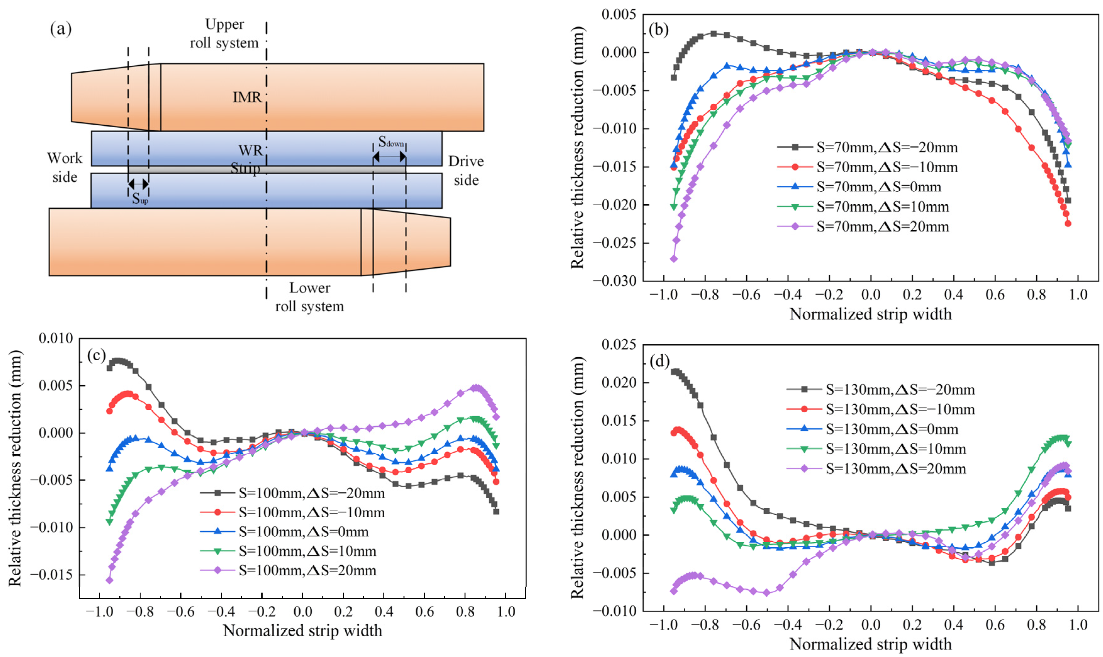
Variations in the amount of roll tampering alter the distribution of the contact force and the form of the roll gap. For an S6-High mill, IRS predominantly modifies the taper coverage of the strip, as illustrated in Figure 8a [21]. As such, the benchmark for taper coverage is established from the upper roll system, and the amount of roll tampering in the lower roll system is then adjusted accordingly. This is defined by Equation (8). During actual production, the taper coverage typically ranges approximately 100 mm, depending on the steel grade; hence, asymmetric taper coverage was used as the control indicator. The specific working conditions were designed as shown in Table 4 for a base IRB of 0 kN. The profile of the section after rolling is shown in Figure 8b–d.
where is the difference in taper coverage between the upper and lower roller systems, is the taper coverage of the upper roller system, and is the taper coverage of the lower roller system.
IRS has a greater impact on the secondary convexity shape of the strip, as evidenced by the total secondary convexity gradually transitioning from negative to positive values as the amount of taper coverage increases. Furthermore, since the amount of asymmetric IRS is defined such that it is similar to the amount of asymmetric roll bending, the modifications to the cross-sectional profile on the WS are less pronounced than those on the DS. To more clearly express the effects of asymmetric scrap volume on the strip’s cross-sectional profile, the scrap volume control characteristics are defined as illustrated in Equation (9). The calculation results are presented in Figure 9.
Based on the above graph, it can be seen that changes in the amount of asymmetric IRS have a linear effect on the primary convexity and secondary asymmetric convexity. Nonetheless, its control efficiency is different from that of asymmetric IRB and exhibits an opposite trend. This is due to the definition of asymmetric IRS in this study, which is not the actual amount of IRS but the amount of taper coverage. It has an inverse relationship with the actual amount of IRS. For fourth- and sixth-order asymmetric convexity, their variations also exhibit significant nonlinearity, with the overall numerical values being relatively small. By comparing with the control efficiency of asymmetric IRB shown in Figure 7, it can be concluded that the unit asymmetric IRS has a greater ability to modify the nonsymmetric convexity of the strip.
5. Combined Effect of Asymmetrical IRB and IRS
As stated in the previous section, the influence of asymmetric bending rolls on the cross-sectional shape of the strip is primarily concentrated on the primary convexity and secondary asymmetric convexity. To control the primary convexity, the roll tilting control mechanism is commonly utilized in practical production processes. Therefore, the focus should be shifted to the control of secondary asymmetry. In addition, a coupling effect between the amounts of IRB and the IRS exists in the strip shape control mechanism of rolling mills [22]. Consequently, the coupling relationship between the impact of varying IRS amounts on asymmetric IRB and that of different IRB on asymmetric IRS should be analysed. Afterward, the counteraction and superposition of asymmetric IRB and asymmetric IRS can be studied through control efficiency analysis.
5.1. Influence of IRB and IRS on Asymmetric Shape Control
Changes in IRS amount will alter the distribution of contact stresses between rolls and, consequently, affect the bending roll’s ability to control the strip shape. Therefore, it is necessary to analyse the impact of asymmetric bending rolls on asymmetric secondary convexity under different IRS amounts. The control effects of asymmetric bending rolls will be designed separately at positions with base taper coverage of 70 mm, 100 mm, and 130 mm, as shown in Figure 10.
The change in the amount of baseline taper coverage will change the length of contact between the intermediate roll and the working roll and the back-up roll, giving the bending roll force more room for regulation. However, as seen from the above graph, the upper and lower limits of the regulation of the asymmetric intermediate roll bending force are basically the same for with different benchmark taper roll amounts, which also indicates that the evaluation system established in this paper can separate the amount of asymmetry from the secondary convexity. The graph also demonstrates that the change in the amount of roll tampering can cause a change in the regulation efficacy of the asymmetric bending roll, but the overall change is not significant. The difference between the highest point is approximately 0.0011 mm, and the lowest point is 0.0018 mm, which has almost no effect on the asymmetry of the strip section profile.
Next, the variation in the regulation range of the amount of asymmetric IRS for different IRBs is analysed, as shown in Figure 11.
This graph reveals a remarkable change in the regulation capacity of asymmetric IRS with varying IRB. Specifically, the regulation range is the smallest at the 0 kN position and gradually increases as the bending force value rises. The difference between the highest point and the lowest point is approximately 0.0067 mm and 0.0086 mm, respectively.
5.2. Equivalence of Asymmetric IRB and IRS
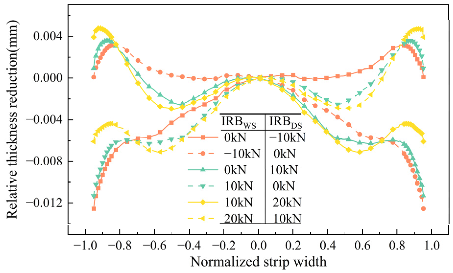
The modulation efficiency of asymmetric IRB and IRS, calculated in Section 4 of this research, is utilized to randomly select working conditions where both asymmetric IRB and IRS have positive and negative values of at different levels. Figure 12 illustrates the regulation ability of asymmetric secondary convexity through the asymmetric flatness regulating mechanism under such defined working conditions, as specified in Table 5. The simulation results of this study are presented in Figure 13.
From the above graph, it is evident that under the same baseline amount of IRS, the uneven sectional contour caused by asymmetric IRS can be compensated for by asymmetric IRB. Therefore, it can be assumed that the effects of the asymmetric IRB and IRS are mutually independent. To further verify this idea, in practical production, asymmetric bending rolls and asymmetric roll shifting are often used in combination as a means of asymmetrical strip shape control. However, a single asymmetrical control parameter that is too large often leads to excessive torques and equipment damage. Therefore, based on the previously proposed independent characteristics of asymmetric bending and roll shifting, this research studied the changes that occurred under the combined effect of these two rolls with the same asymmetrical secondary convexity values. Two working conditions were selected: one where both IRB and IRS were varied, and on where only IRS was varied. The working conditions are shown in Table 6, and the strip shape after rolling is shown in Figure 14. It is evident that the strip shapes after the rolling’s asymmetrical secondary convexity are roughly equivalent.
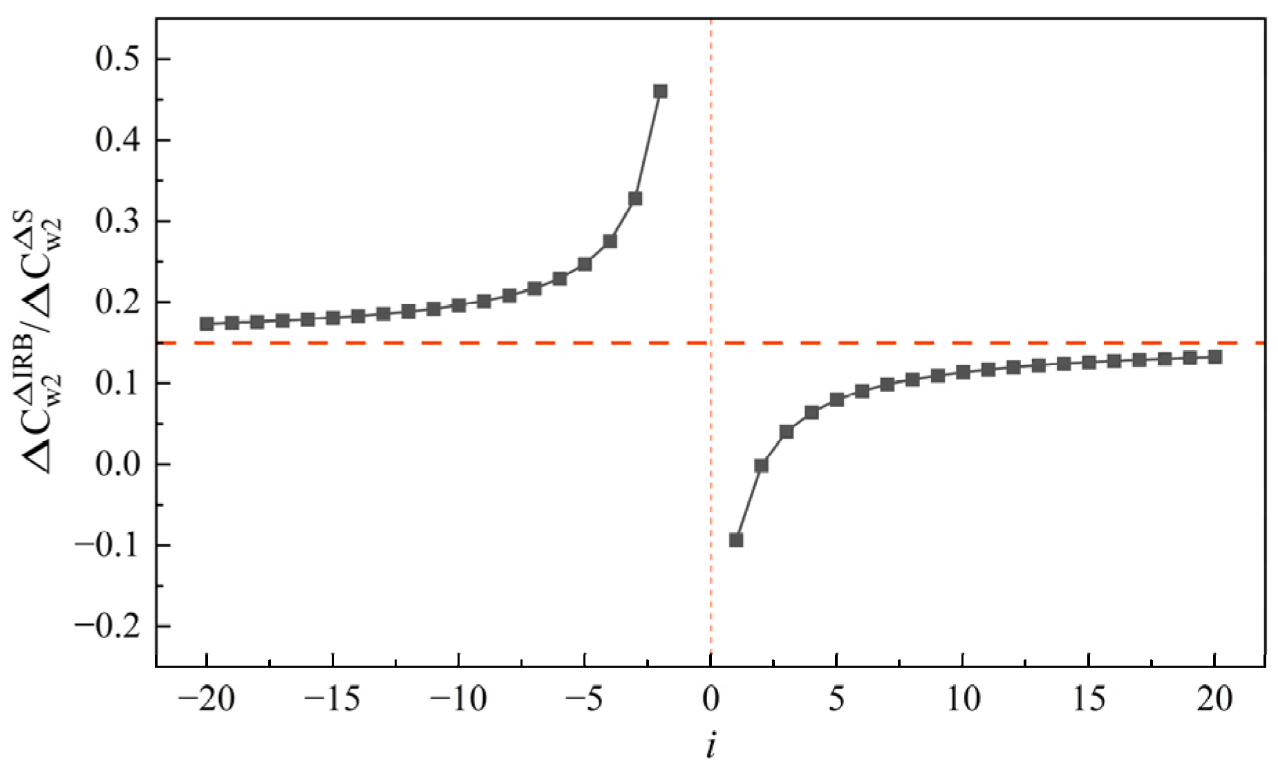
Therefore, taking the benchmark taper coverage of 100 mm and the benchmark IRB of 0 kN as an example, the calculation of the equivalent relationship between asymmetric lateral shifting rollers and asymmetric bending rollers is performed. The computational results are presented in Figure 15.
From the above figure, it can be observed that the equivalent coefficient gradually approaches 0.15 as the asymmetry value increases. In other words, a change of approximately 0.15 mm in asymmetrical IRB (1 kN) corresponds to the asymmetrical secondary convexity due to the asymmetrical IRS. Simultaneously, the distribution pattern resembles a power-exponential function. Taking the zero point as the boundary, it exhibits a symmetric distribution. As the asymmetry value approaches the vicinity of zero, the equivalent relationship between the asymmetrical IRB and IRS tends towards infinity, indicating the difficulty in distinguishing the relationship between the two at that point. However, with the gradual increase in the asymmetry value, the equivalent relationship becomes more stable, and the independence of the IRB and IRS gradually emerges.
6. Application
The results of the research were applied to a 1450 S6-high cold rolling mill production line to observe the shape and count the number of incoming and outgoing strips during the production process and to analyse the asymmetric phenomenon, as shown in Figure 16. In the process of producing 65 Mn strip steel, it is difficult to move the rolls using the online control system during the rolling process due to excessive rolling forces. Therefore, the amount of asymmetric IRS was preset according to the historical production data, and the asymmetric strip shape was then controlled by the online strip shape control system. The incoming strip shape and the finished strip shape before optimization are shown in Figure 17a. According to the equivalent relationship between strip flatness and section profile [23], the main design condition is that the taper coverage of the lower roll system is less than 15 mm of the upper roll system, and the asymmetric IRB is automatically controlled by the automatic shape control system. The optimized finished flatness is shown in Figure 17b.
As seen from the above graph, the asymmetric strip shape problem has clearly been improved, and in the production process, no production accidents occurred, which proves that the superimposed effect of asymmetric IRB and IRS can effectively improve the flatness situation. Similarly, the asymmetric shape problem in the production of other high-strength steels such as DP780 and DP980 was studied and a the research method in this paper was applied to them, and the asymmetric shape was significantly reduced.
7. Conclusions
- A simulation model of an S6-High mill was constructed and validated using the ABAQUS software. When simulating with actual production process parameters, the amount of error in the thickness reduction was 1.4%, while the error in the side-supported roll system’s force, unique to the eighteen-roll mill, was 7.2%, serving as a validation reference. The model has a high simulation accuracy.
- An evaluation index of asymmetric shape was constructed using the method of subtracting the amounts of WS and DS thickness reduction after mirroring. The model was applied to simulate multiworking conditions, analysing the independent and coupled effects of asymmetric IRB and IRS. The asymmetric shape control method has a linear relationship with first- and second-order asymmetrical convexity changes but exhibits a significant nonlinear relationship with fourth- and sixth-order asymmetrical convexity changes when adjusting asymmetric IRB and IRS.
- The variation trend of the effectiveness of the asymmetric shape control mechanism under different baseline shape controls is analysed. The results show that increasing the baseline IRS amount does not have a significant impact on asymmetric IRB’s control ability. However, the control ability of the asymmetric IRS exhibits substantial changes with the variation in the IRB. Furthermore, the equivalent relationship between asymmetric IRB and IRS was constructed and it was proved that, under the same baseline conditions, the two means are equivalent in either cancelling each other out or being added together.
- The calculation results were applied in the field to analyse the historical incoming strip shape and the finished strip shape, and the simulation results are combined with the predetermined amount of asymmetric IRS. The application results show that the asymmetric IRB and IRS can solve the primary and secondary asymmetric shape problems in the production process of the mill and prove the validity and accuracy of this paper’s research, which can provide theoretical guidance for the actual production process.
Author Contributions
Conceptualization, T.Y. (Tieheng Yuan) and T.Y. (Tingsong Yang); methodology, W.S. and T.Y. (Tieheng Yuan); software, T.Y. (Tieheng Yuan); validation, R.G.; formal analysis, R.G. and T.Y. (Tieheng Yuan); investigation, T.Y. (Tieheng Yuan) and T.Y. (Tingsong Yang); resources, W.S.; data curation, R.G.; writing—original draft preparation, T.Y. (Tieheng Yuan); writing—review and editing, T.Y. (Tingsong Yang); visualization, T.Y. (Tieheng Yuan); supervision, W.S. and R.G.; project administration, W.S.; funding acquisition, T.Y. (Tingsong Yang). All authors have read and agreed to the published version of the manuscript.
Funding
This research was funded by the National Key Technologies Research and Development Program (Grant Number: 2023YFB3812602), and the recipient of the funding is Tingsong Yang.
Data Availability Statement
The data presented in this study are available on request from the corresponding author due to privacy.
Conflicts of Interest
The authors declare no conflicts of interest.
References
- Wang, X.C.; Liang, Z.G.; Yang, Q.; Du, X.Z.; Liu, H.Q.; Zhang, Y. Asymmetric shape control theory and practice in cold strip mills. Adv. Mater. Res. 2011, 145, 204–209. [Google Scholar] [CrossRef]
- Xu, Y.; Wang, D.; Liu, H.; Duan, B.; Yu, H. Flatness Defect Recognition Method of Cold Rolling Strip with a New Stacked Generative Adversarial Network. Steel Res. Int. 2022, 93, 2200284. [Google Scholar] [CrossRef]
- Wen, J.; Zhang, Q.D.; Zhang, X.F.; Ye, X.W. Influence of roll profile configuration on high-strength strip flatness control performance in tandem cold rolling. Adv. Mater. Res. 2011, 145, 210–215. [Google Scholar] [CrossRef]
- Jiang, Z.Y.; Du, X.Z.; Du, Y.B.; Wei, D.B.; Hay, M. Strip shape analysis of asymmetrical cold rolling of thin strip. Adv. Mater. Res. 2010, 97, 81–84. [Google Scholar] [CrossRef]
- Chen, Y.; Peng, L.; Wang, Y.; Zhou, Y.; Li, C. Prediction of tandem cold-rolled strip flatness based on Attention-LSTM model. J. Manuf. Process. 2023, 91, 110–121. [Google Scholar] [CrossRef]
- Park, J.; Kim, B.; Han, S. Reinforcement Learning With Model-Based Assistance for Shape Control in Sendzimir Rolling Mills. IEEE Trans. Control Syst. Technol. 2022, 31, 1867–1874. [Google Scholar] [CrossRef]
- Valigi, M.C.; Papini, S. Analysis of chattering phenomenon in industrial S6-high rolling mill. Diagnostyka 2013, 14, 3–8. [Google Scholar]
- Wu, S.; Shao, Y.; Wang, L.; Yuan, Y.; Mechefske, C.K. Relationship between chatter marks and rolling force fluctuation for twenty-high roll mill. Eng. Fail Anal. 2015, 55, 87–99. [Google Scholar] [CrossRef]
- Wang, Z.H.; Gao, Q.J.; Chao YA, N.; Xia, Z.Y.; Zhang, Y.B. Calculation and Analysis of Force in Roll System of 20-High Sendzimir Mill. J. Iron Steel Res. Int. 2013, 20, 33–39. [Google Scholar] [CrossRef]
- Zhou, G.; He, A.; Liu, C.; Zhou, M.; Qin, J.; Liu, Z. Modeling and Simulation of Wide Commercial Pure Titanium Strip Rolling on Sendzimir 20-high Mill. Rare Met. Mater. Eng. 2020, 49, 2333–2339. [Google Scholar]
- Zhang, Y.; Yang, Q.; Wang, X.C. Control strategies of asymmetric strip shape in six-high cold rolling mill. J. Iron Steel Res. Int. 2011, 18, 27–32. [Google Scholar] [CrossRef]
- Yan, Z.W.; Bu, H.N.; Li, H.; Hong, L. Numerical simulation analysis of the rolling process based on the particle swarm hybrid algorithm. Ironmak. Steelmak. 2023, 50, 1321–1330. [Google Scholar] [CrossRef]
- Wang, P.F.; Zhang, W.X.; Wang, Y.H.; Zhang, D.H. Analysis of Actuator Performance Based on Actuator Efficiency in Flatness Control of Cold Rolling Mill. Adv. Mater. Res. 2011, 154, 344–348. [Google Scholar] [CrossRef]
- Prinz, K.; Steinboeck, A.; Müller, M.; Ettl, A.; Kugi, A. Automatic gauge control under laterally asymmetric rolling conditions combined with feedforward. IEEE Trans. Ind. Appl. 2017, 53, 2560–2568. [Google Scholar] [CrossRef]
- Alvarez, J.C.; Diez, A.B.; Alvarez, D.; Gonzalez, J.A.; Obeso, F. Thick unevenness compensation in a hot rolling mill having automatic gage control. IEEE Trans. Ind. Appl. 2002, 38, 559–564. [Google Scholar] [CrossRef]
- Cao, J.G.; Chai, X.T.; Li, Y.L.; Kong, N.; Jia, S.H.; Zeng, W. Integrated design of roll contours for strip edge drop and crown control in tandem cold rolling mills. J. Mater. Process. Tech. 2018, 252, 432–439. [Google Scholar] [CrossRef]
- Hai, Y.; Yang, T.; Wang, H.; Xu, Z.; Fan, M. Roll profile preset and control based on electronic temperature control technology. Metall. Res. Technol. 2022, 119, 512. [Google Scholar] [CrossRef]
- Sun, J.; Shan, P.F.; Wei, Z.; Hu, Y.H.; Wang, Q.L.; Peng, W.; Zhang, D.H. Data-based flatness prediction and optimization in tandem cold rolling. J. Iron Steel Res. Int. 2021, 28, 563–573. [Google Scholar] [CrossRef]
- Bu, H.N.; Zhou, H.G.; Yan, Z.W.; Zhang, D.H. Multi-objective optimization of bending force preset in cold rolling. Eng. Comput. 2019, 36, 2048–2065. [Google Scholar] [CrossRef]
- Wang, P.; Jin, S.; Li, X.; Huang, H.; Wang, H.; Zhang, D.; Yao, Y. Optimization and prediction model of flatness actuator efficiency in cold rolling process based on process data. Steel Res. Int. 2022, 93, 2100314. [Google Scholar] [CrossRef]
- Wang, Q.L.; Li, X.; Hu, Y.J.; Sun, J.; Zhang, D.H. Numerical analysis of intermediate roll shifting–induced rigidity characteristics of UCM cold rolling mill. Steel Res. Int. 2018, 89, 1700454. [Google Scholar] [CrossRef]
- Song, M.; Liu, H.; Xu, Y.; Wang, D.; Huang, Y. Decoupling adaptive smith prediction model of flatness closed-loop control and its application. Processes 2020, 8, 895. [Google Scholar] [CrossRef]
- Chen, L.; Sun, W.; He, A.; Liu, C.; Qiang, Y. Study on quarter-wave generation mechanism in DP980 steel during cold rolling. Int. J. Adc. Manuf. Tech. 2022, 120, 313–327. [Google Scholar] [CrossRef]
Figure 1.
Finite element model assembly.

Figure 2.
Schematic diagram of side support, work roll positions, and forces.

Figure 3.
Comparison of different fitting orders.

Figure 4.
Schematic diagram of asymmetric shape fitting.

Figure 5.
Section shape after rolling: (a) IRB = −100 kN; (b) IRB = 0 kN; (c) IRB = 100 kN; (d) IRB = 200 kN.
Figure 5.
Section shape after rolling: (a) IRB = −100 kN; (b) IRB = 0 kN; (c) IRB = 100 kN; (d) IRB = 200 kN.

Figure 6.
Comparison of shape after rolling under symmetrical working conditions.

Figure 7.
Efficacy of asymmetric IRB of each order: (a) ; (b) ; (c) ; (d) .

Figure 8.
Section shape after rolling. (a) Schematic diagram of asymmetric IRS; (b) S = 70 mm; (c) S = 100 mm; (d) S = 130 mm.
Figure 8.
Section shape after rolling. (a) Schematic diagram of asymmetric IRS; (b) S = 70 mm; (c) S = 100 mm; (d) S = 130 mm.

Figure 9.
Efficacy of asymmetric IRS of each order: (a) ; (b) ; (c) ; (d) .

Figure 10.
The control ability of asymmetric IRB under different IRS.

Figure 11.
The control ability of asymmetric IRS under different IRBs.

Figure 12.
Comparison of equivalent shape control efficacy.

Figure 13.
Comparison of strip shape after rolling with equivalent working conditions.

Figure 14.
Comparison of strip shape after rolling for superimposition working conditions.

Figure 15.
Equivalent Relationship between IRB and IRS.

Figure 16.
S6-High Cold Rolling Mill.

Figure 17.
Flatness during actual production (a) before optimization and (b) after optimization.


Table 1.
Roller system parameter configuration.
| Roll | Length/mm | Diameter/mm |
|---|---|---|
| Back-up Roll (Body/Neck) | 1450/580 | 1200/690 |
| Intermediate roll (Body/Neck) | 1720/450 | 370/230 |
| Work Roll (Body/Neck) | 1450/335 | 170/120 |
| Side Support Roll (Body/Neck) | 1450/90 | 168/90 |
| Back-up Bearing Roll | 75 × 15 | 150 |
Table 2.
Rolling parameters.
| Rolling Parameters | Value | Rolling Parameters | Value |
|---|---|---|---|
| Rolling Pass | 1 | Strip width (mm) | 1250 |
| Rolling Force (kN) | 8455 | Strip thickness (mm) | 4.3 |
| IRB (kN) | 180 | Front unit tension (MPa) | 3.5 |
| Taper coverage (mm) | 100 | Back unit tension (MPa) | 12.1 |
Table 3.
Asymmetric IRB working conditions design.
| IRB/kN | DIRB/kN |
|---|---|
| −100 | −100, −50, 0, 50, 100 |
| 0 | −100, −50, 0, 50, 100 |
| 100 | −100, −50, 0, 50, 100 |
| 200 | −100, −50, 0, 50, 100 |
Table 4.
Asymmetric IRS working conditions design.
| Coverage of IMR Taper/mm | Coverage Difference/mm |
|---|---|
| 70 | −20, −10, 0, 10, 20 |
| 100 | −20, −10, 0, 10, 20 |
| 130 | −20, −10, 0, 10, 20 |
Table 5.
Equivalent IRS and IRB working conditions design.
| Working Condition | IRB/kN | DIRB/kN | S/mm | DS/mm |
|---|---|---|---|---|
| A1 | 0 | −40 | 100 | 6 |
| A2 | −100 | −50 | 100 | 8 |
| A3 | 100 | −80 | 100 | 11 |
| A4 | 200 | −90 | 100 | 12 |
Table 6.
Superimposition relationship of asymmetric IRS and IRB working conditions design.
| IRB/kN | DIRB/kN | S/mm | DS/mm | Theory DCw2/mm |
|---|---|---|---|---|
| 0 | 60 | 100 | 10 | ≈0.017 |
| 0 | 0 | 100 | 19 | ≈0.017 |
Disclaimer/Publisher’s Note: The statements, opinions and data contained in all publications are solely those of the individual author(s) and contributor(s) and not of MDPI and/or the editor(s). MDPI and/or the editor(s) disclaim responsibility for any injury to people or property resulting from any ideas, methods, instructions or products referred to in the content. |
© 2024 by the authors. Licensee MDPI, Basel, Switzerland. This article is an open access article distributed under the terms and conditions of the Creative Commons Attribution (CC BY) license (https://creativecommons.org/licenses/by/4.0/).
Share and Cite
MDPI and ACS Style
Yuan, T.; Sun, W.; Guo, R.; Yang, T. Asymmetric Shape Control Ability and Mutual Influence of the S6-High Cold Rolling Mill. Metals 2024, 14, 507. https://0-doi-org.brum.beds.ac.uk/10.3390/met14050507
AMA Style
Yuan T, Sun W, Guo R, Yang T. Asymmetric Shape Control Ability and Mutual Influence of the S6-High Cold Rolling Mill. Metals. 2024; 14(5):507. https://0-doi-org.brum.beds.ac.uk/10.3390/met14050507
Chicago/Turabian StyleYuan, Tieheng, Wenquan Sun, Ruichun Guo, and Tingsong Yang. 2024. "Asymmetric Shape Control Ability and Mutual Influence of the S6-High Cold Rolling Mill" Metals 14, no. 5: 507. https://0-doi-org.brum.beds.ac.uk/10.3390/met14050507
Note that from the first issue of 2016, this journal uses article numbers instead of page numbers. See further details here.