Thermomechanical Grain Refinement in AA6082-T6 Thin Plates under Bobbin Friction Stir Welding


1
Department of Mechanical Engineering, University of Canterbury, Christchurch 8140, New Zealand
2
Advanced Manufacturing Centre, Fakulti Kejuruteraan Pembuatan, Universiti Teknikal Malaysia Melaka, 76100 Durian Tunggal, Melaka, Malaysia
*
Author to whom correspondence should be addressed.
Metals 2018, 8(6), 375; https://0-doi-org.brum.beds.ac.uk/10.3390/met8060375
Submission received: 29 March 2018
/
Revised: 16 May 2018
/
Accepted: 18 May 2018
/
Published: 23 May 2018
(This article belongs to the Special Issue Recent Achievements in Rotary, Linear and Friction Stir Welding of Metals Alloys)
Abstract
:Bobbin friction stir welding (BFSW), with its fully penetrated pin and double-sided shoulder, can provide high rates of heat generation. This produces solid-state thermo-mechanical grain refinement. In this paper, the microstructure evolution of the welded joints of AA6082-T6 obtained using BFSW process was investigated with a focus on grain refinement. Two sheets of the AA6082-T6 alloy were butt-welded with a fixed-gap bobbin tool. The microstructure at a mid-weld transverse cross-section was evaluated using optical microscopy and electron backscatter diffraction (EBSD). Significant grain refinement was observed, with a decrease in grain size from 100 μm in directional columnar grain morphology of the base metal, to an ultrafine size—less than 10 μm—for the equiaxed grains in the stirring zone. The EBSD results showed that with BFSW processing, secondary phase precipitation patterns were produced that are distinct from the primary artificial age-hardening precipitates created by the T6 tempering cycle. The severe plastic deformation and heat generation appear to accelerate dynamic recrystallization and precipitation during the BFSW process. The microstructural studies confirmed that the BFSW process can provide a highly efficient thermodynamically activated grain refinement in the solid-state without requiring additional processes such as heat treatment or external means of grain refinement.
1. Introduction
1.1. Context
The friction stir welding (FSW) process was invented and patented by The Welding Institute (TWI) [1] to create solid-state bonding using a non-consumable tool that rotates and mechanically travels through the workpieces to be joined. The initial design was for a single-shoulder tool, the conventional-FSW (CFSW). TWI then introduced a further improvement in the form of a tool with two shoulders that penetrated through the whole weld section [2,3,4]. This bobbin FSW (BFSW) process is a cheaper manufacturing technique with potentially higher productivity. Additionally, it is highly repeatable, offering a rapid butt-joint by using a double-sided and fixed-gap bobbin tool [4]. The formation of the weld occurs through the mixing of the plasticized mass. Due to the combination of tool rotation and forward linear motion, there is an advancing side (A.S) and a retreating side (R.S). This results in different internal flow trajectories and the formation of a bonding layer in a solid-phase process [5].
The greater heat generation in BFSW compared with CFSW has a considerable effect on the thermal experience of the grains, and consequently can benefit the microstructure. The solid phase plastic deformation implemented in the BFSW process has a good potential for a thermomechanical grain refinement [6,7]. However, it is difficult to realize these benefits in some materials. A specific example is marine grade AA6082-T6 aluminum alloy, which suffers from poor weldability when used in thin plates. This work presents a set of microscopic analyses of this alloy, investigating the dynamic recrystallization and precipitation as the principles of the grain refinement during BFSW process.
1.2. Background
Friction Stir Welding is a solid-phase joining technique whereby the combination of the pressure (from the forging force of the tool) and the heating (caused by the friction between the tool and the workpiece) produces a high-strength bond, hence avoiding solidification defects [8]. During the FSW process, the deformed metal is changed from a solid phase into a mushy-like state. This thermomechanical stirring of the plasticized mass eventually leads to formation of a welded joint under the pressure and heat input [9,10].
While most FSW research is performed using conventional FSW tools, there are possible benefits to using the bobbin tool that make is attractive to implement as part of the FSW process [11]. BFSW develops a double-sided weld with the advantage of the elimination of the root flaws in butt joints and also the removal of the need for a backing anvil or heavy fixturing as part of the process set-up. This results in less component distortion than CFSW due to a more uniform/balanced heat input. In addition, for a fixed-gap bobbin tool, there are only two process variables to control: rotation speed (ω), and travel speed (V) [12,13]. In BFSW, the backing anvil of CFSW is replaced by a self-reactive bottom shoulder and the axial engagement force (to keep the tool in the substrate) is compensated by a self-adaptive compression ratio at the shoulder gap [12].
Based on BFSW trials, it has been suggested that as the tool rotates through the workpiece, the created friction leads to an increase in temperature in the material around the tool, which promptly yields a plasticized zone [14]. This is the stirring zone. As the tool progresses through the weld-line, the stirred mass is squeezed (extruded) under the pressure of the shoulders and consolidates behind the pin to form a bond [15,16]. As opposed to fusion welding, no melting happens in the FSW process, and the final weld-seam forms in a fine-grained microstructure without any solidification.
The BFSW process was originally developed for specific industrial exploitation, e.g., implementation in aerospace, transportation and marine industries [17]. Successful welding of aluminum alloys is one of the main advantages of this technique, compared to the more demanding setup requirements for fusion welding. The marine grade AA6082-T6 aluminum is an attractive industrial choice for processing with the FSW technique. Suitable machinability and excellent corrosion resistance have seen the application of AA6082-T6 in shipbuilding and bridges [18].
However, in practice the FSW process causes macrostructural flaws in AA6082-T6 resulting in poor performance after welding [10]. Unfortunately for problem-solving purposes, the AA6082-T6 material responds poorly to conventional etchants which are commonly use for the metallography of aluminum alloys [19,20]. This makes it difficult to observe the microstructure of the weld: the grain boundaries and internal flow features are difficult to resolve [20,21]. Therefore, determining the origins of defects is problematic. Consequently, it has been necessary to modify the composition of etchants and the process of application, and these techniques have only recently become available [20].
AA6082-T6 is an Al-Si-Mg alloy which has a stabilized microstructure by addition of manganese (Mn) [22]. The typical element composition is given in Table 1. The thin plates of wrought AA6082-T6 are rolled and then tempered during T6 heat treatment cycle to stabilize the microstructure and improve the mechanical properties [23]. The T6 is a precipitation-hardening tempering that includes three time-temperature cycles; first, solutionizing of the primary microstructure, quenching of the grains, and finally an artificial ageing by tempering heating [24]. Details of the T6 tempering for AA6082 are available [20,25]. In general, quenching can form a single-phase supersaturated solid phase, this can cause a solid solutionizing strengthening [26]. The heat input during the BFSW processing can change precipitation hence alter the T6 condition [27]. Therefore, the BFSW process may cause detrimental effects on the metallurgical and mechanical properties of the AA6082-T6 workpiece.
Performance assessment and optimization of the AA6082-T6 BFSW welds need to be evaluated by metallurgical analysis of the grain microstructure and phase characterization to see how much the artificial aging properties are affected by the process condition/parameters.
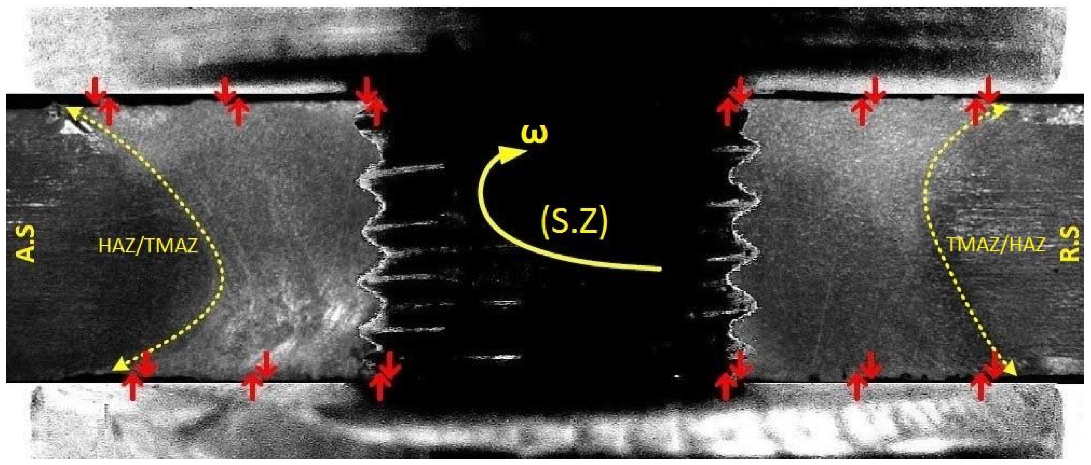
Microscopic observation of the BFSW weld reveals that the grain size and distribution of the weld region is typically affected by a plasticity-induced transition in morphology [28]. In general, there are three typical zones through the macrostructure of the cross section of the BFSW weld. The central region of the weld, which is the location of the direct interaction of the pin and the workpiece, is termed the stir zone (S.Z). It is characterized by hourglass borders (Figure 1) at the A.S and the R.S of the weld [21]. In S.Z, the distorted and fragmented grains are thermomechanically plasticized by the rotation of the tool, and then the stirred mass is dynamically recrystallized after the consolidation and cooling of the weld mass [29]. The next region after the S.Z towards the base metal (B.M) is the thermomechanical affected zone (TMAZ). The effects of the complex interaction between the friction, heat input and stirring action create a different thermal and mechanical induced microstructure at the proximity of the S.Z [26]. Similar to other weld types, the heat affected zone (HAZ) is a region of the base metal closer to the weld, and experiences some thermal flux effects during the welding which creates a transitional microstructure [30].
Grain refinement is a metallurgical process that makes the alloy stronger (strength, ductility and toughness) by increasing the number of grains or modifying the grain morphology. Grain refinement can be achieved by heat treatment, adding alloying elements to the liquid phase during solidification, or plastic deformation (thermomechanical work). These can activate recrystallization mechanisms or change the grain growth behavior through the microstructure. In all these processes, by increasing the density of grain boundaries (G.B), the dislocation defects are blocked, which leads to strengthening within the polycrystalline structure. Al alloys respond well to thermomechanical processing, whereby the grain refinement can be dynamically obtained with control of the grain morphology as well as limiting grain growth.
In some specific alloys (e.g., 6xxx aluminum alloys), the strengthening mechanism can be via precipitation as the secondary phase. Nucleation of the hardening precipitates in a fine distribution—which is embedded in the crystalline lattice of the solid solution—can form obstacles against dislocation movement; this acts as another strengthening mechanism.
1.3. Purpose and Approach
The heat-treated microstructure of AA6082-T6 contains a uniform and stabilized solid solution which has been super-saturated by the artificial age-hardening. The T6 tempering condition retains the hardening particles in the solid solution matrix as opposed to precipitating them in grain boundaries where there are natural sites of nucleation. However, it is expected that the solid phase plastic deformation of the BFSW process fragments the grains to ultrafine and changes the T6 microstructural properties. Published research on microscopic studies of friction stir welded alloys suggests that a form of grain refinement can happen during the CFSW process [6,31,32]; however, it has not been recorded in the literature for the BFSW technique.
To activate the grain refinement mechanisms in solid-phase processes, heat and mechanical work are obviously two main prerequisites. Based on the thermomechanical nature of the process, BFSW could be a good candidate for developing grain refinement.
The aim of this paper is to evaluate the grain refinement mechanism in AA6082-T6 BFSW welds by studying microscopic transformations within the weld texture. Our starting hypothesis is that the driving force for this grain refinement is supplied by grain fragmentation, plastic deformation, and stored strain within the polycrystalline lattice structure, which increases the density of grain boundaries and the blocking of dislocation motion through the microstructure.
The direct observation of the ultrafine grain microstructure is inherently difficult using optical microscopy. More specifically, description of the thermomechanical behavior of the weld needs the fine structure of AA6082-T6 alloy to be revealed in the deformed regions to show the weld texture evolution, grain orientation, size and morphology, based on crystallographic characteristics. We used electron backscatter diffraction (EBSD) for crystallographic measurement of the microstructure, because optical microscopy could not provide enough contrast and resolution to visualize all the microscopic details required for a precise measurement. Note that in optical metallography, the phase contrast is not easily distinguishable, and occasionally the contrast resulting from different etch rates causes a misdiagnosis even on the same material. Hence, using the EBSD as microstructural-crystallographic characterization method can provide a more reliable study of the history of metallurgical transformation phenomena during the BFSW process.
2. Materials and Methods
2.1. Welding Trials
In this research, the BFSW process was performed on AA6082-T6 Al alloy plates with a thickness of 4 mm. The standard element composition of the parent metal is presented in Table 1.
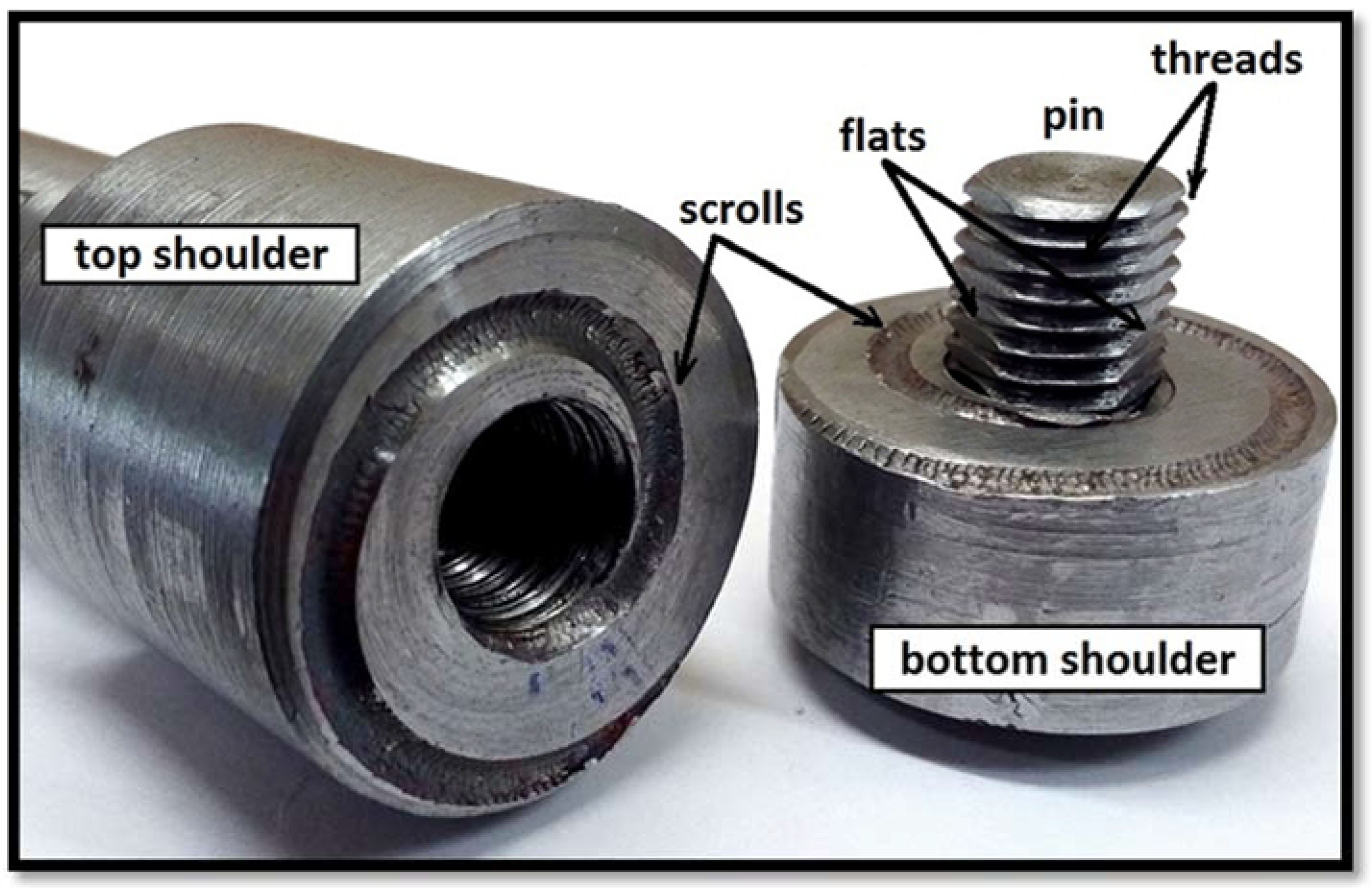
A full-feature bobbin tool with a fixed-gap configuration as per [27,34] was utilized for the weld trials. The tool features include a threaded pin modified by adding three symmetrical flat surfaces (tri-flat), with top and bottom shoulders. Each shoulder had a scroll, which is a spiral groove that is oriented (clockwise or counter-clockwise, as appropriate) to feed material into the center during rotation (Figure 2). In proportion to the 100 HV hardness of the aluminum plates, the welding tool was fabricated from H13 tool steel (560 HV).
The design intent of these features is that the threaded surface of the pin provides a more homogenized stirring condition and creates vertical flow around the pin [21]. The flat features grasp the base material, and prevent clogging of threads by the stirring material [13]. The 360-degree spiral scrolls pump material towards the center of the pin to seal the weld region [18]. The diameter (D) ratio (DShoulder/DPin) was selected as 3:1, consistent with other references. A degree of compression of the base material is required, to make up for mass that is lost to the cross-section from flash and chips that may escape (especially at commencement). The compression ratio is the difference between the gap of the bobbin tool and the thickness of the workpiece plate, relative to the plate thickness, and was set at 3.75% [17]. More details of the bobbin-tool features used for the aluminum weld trials are listed in Table 2.
The weldment plates were cut into two plates with dimensions of 250 mm in length and 75 mm in width and set side-by-side for a butt weld. The feed rate and rotational speed were optimized based on [13,20,25,27]. For this aluminum grade, lower speeds imposed more violence on the tool and did not create a stable weld, and higher speeds led to poorer weld quality in the forms of structural defects (e.g., tunnel void or kissing bond discontinuities).
The aluminum welds were manufactured by a 3-axis CNC machine (2000 Richmond VMC Model, 600 Group Brand, Sydney, Australia) with a Fanuc control unit and motor capacity of 14-horsepower spindle. The direction of tool rotation was clockwise, and the plates were fixed rigidly by strap clamps at the corners. The welding was done in open air with a work temperature of 18 °C at the beginning of the test and no preheating or post-weld heating for the plates. After the BFSW process, the metallography specimens were selected from the middle of the weld-seam.
2.2. Metallography
To make the metallography samples, the weld cross-sections were mounted in thermoplastic hot-pressed resin. Next, the mounted samples were polished by the typical metallography preparation to provide a smooth mirror surface for etching [22]. After micro-polishing of the surface down to 0.5 μm, specimens were etched to identify the grain boundaries. Ultrafine optical observations were achieved, including the grain morphology. This reveals details of the dynamic recrystallization within the weld texture. The etchants typically used in the literature are Weck’s and Keller’s reagents. However, the published results in the literature only show grain boundary patterns, and fail to show adequate results at higher magnification, and therefore cannot show grain refinement features, dynamic recrystallization or precipitation. Instead, these finer features generally require electron microscopy. Recent published work [20] has demonstrated that it is possible to observe these microscopic features using more sophisticated etchant processes. We adapted the compositions of etchants of [20] by emphasizing the etchants compositions that were expected to elucidate grain boundaries and intermetallic compounds.
Our developed etching method comprises a multiple-step immersion of the specimens in an ultrasonic bath at 70 °C during etching. The composition of the reagents and other conditions during the etching (pre-etching, time and temperature) are shown in Table 3.
After etching, the specimens were rinsed with distilled water, cleaned by ethanol, and dried with hot air. Then, typical optical microscope was used for the microscopic observation of the etched cross sections.
2.3. Electron Microscopy
For the electron microscopy analysis, the mounted specimens were re-polished using 9, 3, and 1 μm diamond paste with a final polish of 0.06 μm colloidal silica. Samples were examined with a scanning electron microscope (SEM) (JEOL 6100, JEOL Inc., Peabody, MA, USA) with two detectors. The EBSD detector was an HKL Nordlys III EBSD detector (Oxford Instruments plc, Abingdon, UK) and was used to create EBSD maps for different region of the weld cross section, using traditional clean-up procedures with HKL Tango software (HKL Channel 5 Tango software version 5.12.60.0, Oxford Instruments plc, Abingdon, UK). As the stirring was conducted over the weld locus, the grain size of the sample varied greatly from B.M through to the center of the weld. Thus, to maintain a constant number of pixels for EBSD mapping and estimation of grain size, for small grain-sized regions, a magnification step size of 0.75 μm with an overall acquisition area of ~1/16 mm2 was used. Alternatively, for large grains of B.M region, a step size of 3 μm with an overall acquisition area of 2 mm2 was used. All other control parameters such as binning, probe current, accelerating voltage, and exposure time were held constant. EBSD maps with obscured clarity of the Kikuchi diffraction patterns were rejected. By altering the step size, the average indexing rate of all collected samples was 97.5%, where the unindexed pixels were filled in with the software.
The elemental maps of different weld samples were subjected to an analysis using the same SEM equipped with energy-dispersive X-ray spectrometer (EDS) detector (Oxford Instruments plc, Abingdon, UK). The working voltage for EDS mapping of the aluminum samples was 20 kV. The software used for EDS analysis was AZtecLive & Ultim Max (X-Max version, Oxford Instruments plc, Abingdon, UK).
3. Results and Findings
The typical microstructure distributed in different regions of the BFSW joint is depicted in Figure 3 for the transverse cross-section of the AA6082-T6 weld. The micro-etched samples readily reveal the grain boundary (G.B) contrast, which makes it possible to study the polycrystalline lattice and the grain morphology in different regions of the weld (HAZ, TMAZ, S.Z) compared with the B.M.
3.1. Optical Microscopy
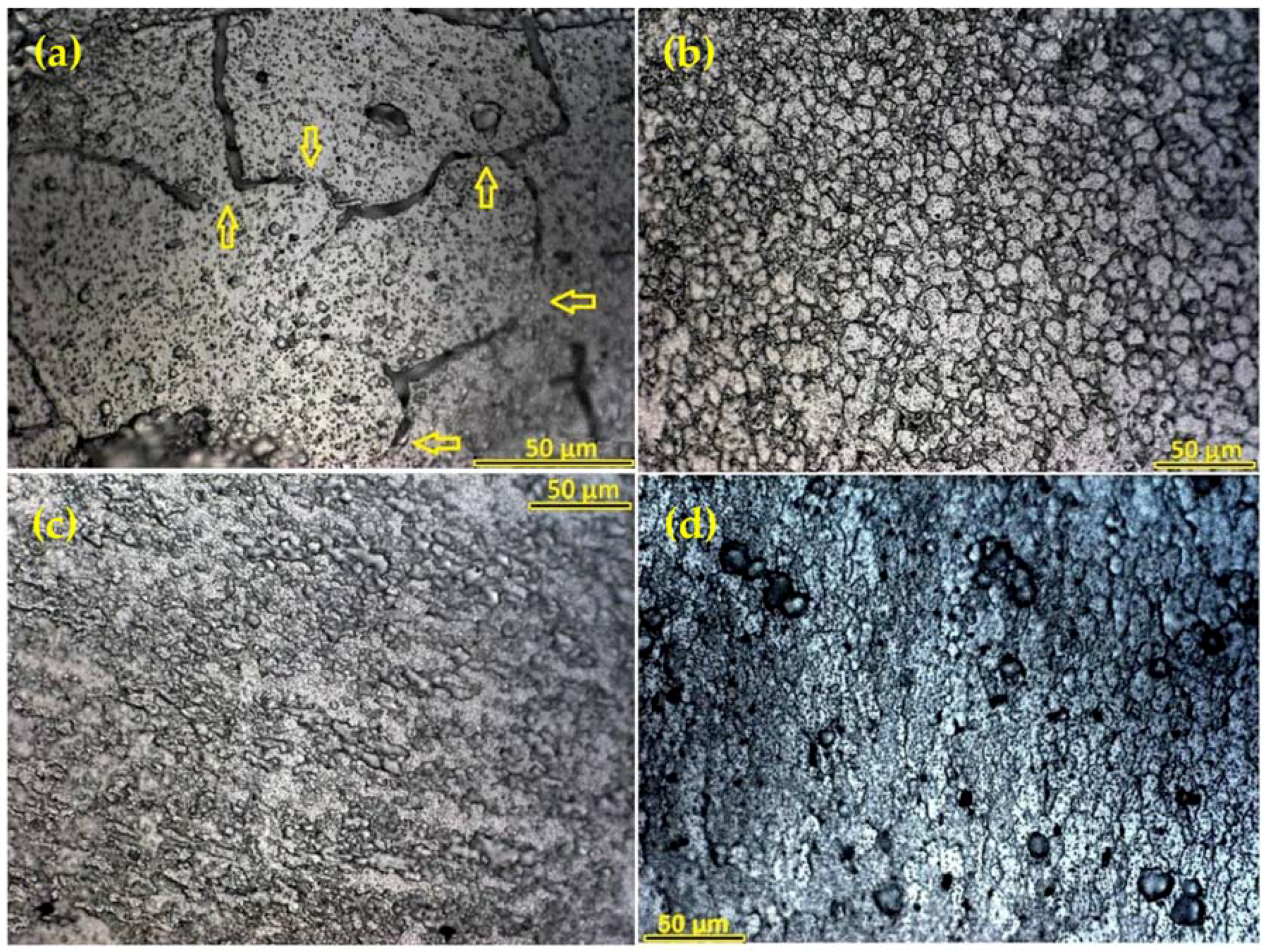
The optical micrographs in Figure 3 demonstrate a variety of grain morphologies from B.M towards the S.Z with a significant change in grains size. The optimized microscopic resolution and contrast also distinguishes between the grains of the HAZ and TMAZ, which are barely distinct in macroscopic measurements. The columnar morphology of the B.M grains changes to equiaxed grain structure with an ultrafine size in the S.Z.
3.1.1. Grain Refinement
The comparative microanalysis of B.M and S.Z regions confirms a distinct modification in grain size and morphology. The 100 μm directional grains of the B.M are converted to fine spherical grains in a narrow range distribution less than 10 μm in the S.Z. These transitions in grain size and morphology may contribute to dynamic recrystallization through the S.Z. It should be noted that the G.B pattern in the B.M is not delineated continuously, and in some places is hardly distinguishable from the grains. This feature may be due to the T6 temper making a uniform/homogenized lattice with motion of the grain boundaries. The grain growth phenomenon can change the shape and location of the grain boundaries (without the need of an applied shear stress) emerging by the discrete lines or disconnections in the plane-view micrographs as the characteristics of the motion of the G.B plane orientations.
It should be noted that stirring reduces the grain size to less than 10 microns with low anisotropy (equiaxed grain structure). Therefore, as a consequence of the recrystallization caused by the mechanical stirring mechanism, a fine homogeneity is observable through the microstructure of the S.Z. This ultrafine condition is likely to contribute to the lack of success with simple conventional etchants.
It should be noted that there is a transitional region between the B.M and S.Z, showing a different morphologic grain structure. HAZ and TMAZ regions, as the interface between B.M and the S.Z, illustrate a plasticity-induced microstructure. The grain structures of the HAZ-TMAZ are refined, but the observed elongated grains are almost identical to the deformation-induced thermal and strain fields, which are directed from the S.Z outwards. The dynamic recrystallization and transition gradient of the grain morphology for the HAZ and TMAZ regions are shown in micrographs Figure 3b,c. The TMAZ in proximity to the weld region shows significant grain distortion, which is directly attributed to the strain field caused by the mechanical work and heat generation in the S.Z. The next region, HAZ, is in the first instance only affected by the heat flux conducted from the S.Z. The micrograph shows different morphology and smaller grain structure compared to the base material, but has similarities to the thermo-mechanical affected zone in terms of the grain size and morphology. We interpret this as a thermally induced reduction in grain size via activation of sub-grain boundaries and formation of new boundaries. It is also possible that strains may be induced in this region during post-welding re-cooling, and this may affect the development of grain attributes.
It seems that the transitional region of HAZ/TMAZ is the place that most clearly illustrates the thermomechanical nature of the BFSW processing. In this regard, we developed additional etchants (see A, B, C, D in Table 3) with higher discrimination to reveal more details of the recrystallization and transition of grain morphology through the microstructure of AA6082-T6 in a finer-scaled microscopic observation.
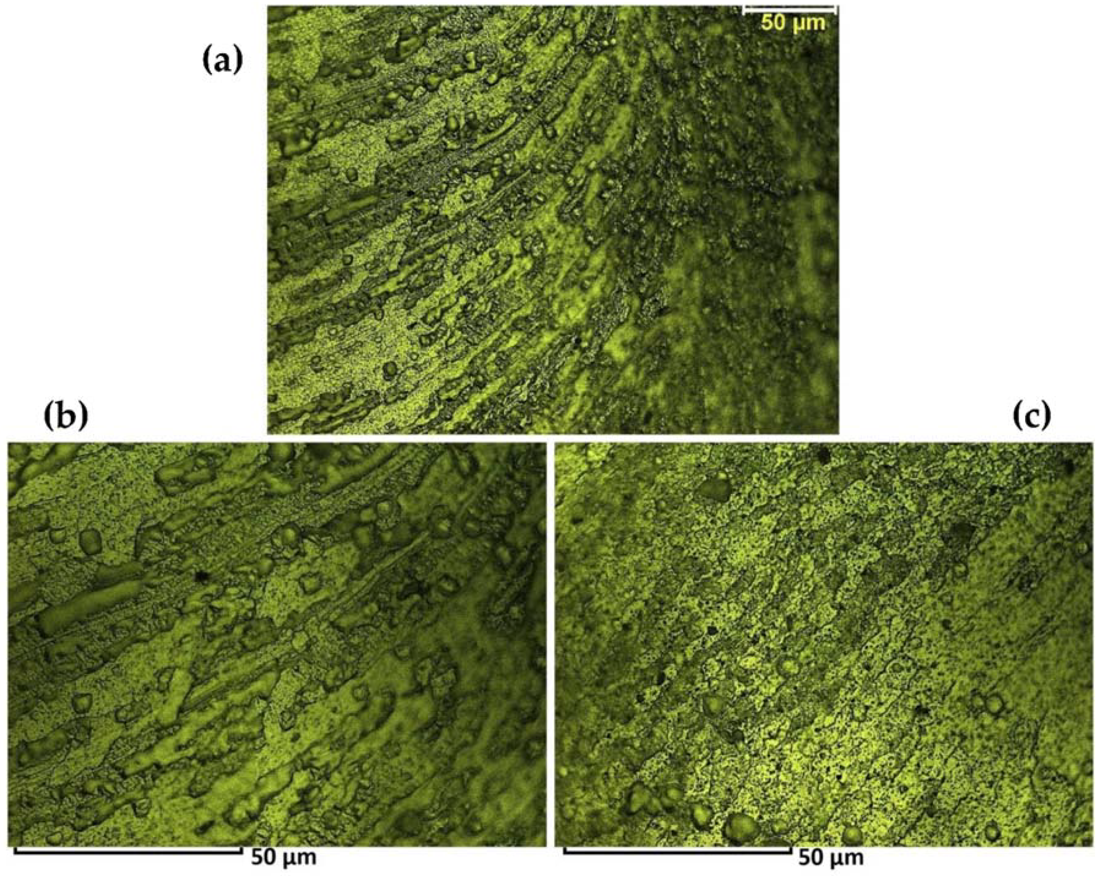
Figure 4 shows the transitional structure of TMAZ in the vicinity of the S.Z, revealing a tapered pattern representative of the morphological flow of grains in an inhomogeneous microstructure. Adjacent to the S.Z a poor distribution of G.B (washed pattern) is observed that is representative of a transformed grain structure (bulging recrystallization) at the entrance of the weld region.
The bulging recrystallization (BLG) is characterized by small recrystallized grains along grain boundaries that have been exposed to mechanical shear stress, see bottom right of Figure 4c. A limited crystal plasticity and an increase in temperature (both induced by the stirring) makes the grains bulge into each other, which results in stress relieving and the release of strain stored in the weld texture. The imposed stress-strain fields can also drive different grain boundary motion mechanisms which will be describe in the following.
Closer to the HAZ region, the micrograph shows a contrasting curved layered structure representing different morphological gradients of the grain distortion between the layers, see Figure 4b. The dynamic nature of the stirring flow causes each plasticized layer during the stirring to have a different thermal and mechanical history, which affects recrystallization. Irrespective of whether grain boundaries are planar or curved, this distinct transition morphology is evidence of the grain misorientation for the TMAZ microstructure.
Complexities of the microscopic details inside the grains are generally evidence of the transformation history that has been preferentially located for the microstructure, and can reveal the grain structure evolution in each specific region of the weld (HAZ, TMAZ or S.Z). These different grain morphological features are representative of the transportation mechanism inside the weld, which likely stabilizes the microstructure.
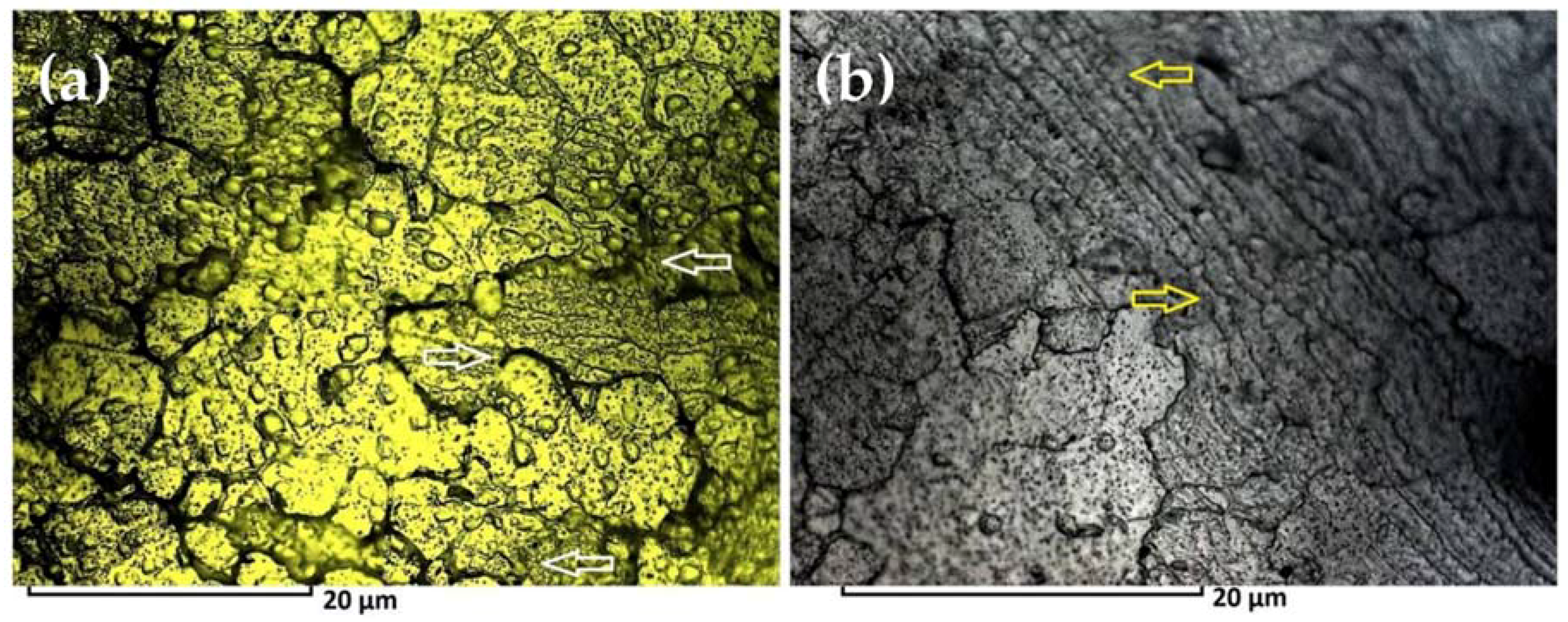
The microstructure of the HAZ/TMAZ region was further analyzed with a different reagent C suitable for high magnification of details, revealing the inner regions of the grains. Subsequent results are shown in Figure 5. Two other transformation features arise in HAZ/TMAZ material, which we describe below.
Figure 5a reveals a discontinuity pattern for the grain boundaries. This is superficially similar to the effect seen in the base material (Figure 3a), but here the features are at smaller scales. We interpret this to be due to the grain boundary migration (GBM) in the form of the movement of the boundary separating two grains. The driving force for grain boundary migration originates from the elastic strain energy stored as dislocations, which in turn is attributed to the shear forces generated during welding. However, temperature is an inherent prerequisite for the mobility of the boundary, as well as the impurity content of both the grains and the boundary. Nevertheless, at higher temperatures, grain boundaries are free to sweep across entire grains.
The microscopic studies suggest a possible mechanism for the grain boundary migration: the applied shear force acts on the disordered boundaries of the now-smaller grains, and causes those boundaries to advance into the grain. The stepping/motion mechanism is accelerated at triple junction points of grain boundaries [35]. The GBM effect is evident in Figure 5a as the discontinuities in grain boundaries.
The outcome of the process is the induction of internal strain and formation of sub-grain boundaries in the same and adjacent grains, and this is evident in Figure 5b as the aligned regions. Sub-grain boundaries (SGBs) are a thermomechanical feature, leading to reduction of internal stresses, specifically in two-dimensional crystals. Strain field mapping of the crystalline structures introduces dislocations which is consistent with the considerable strain along the grain. The observed dynamics demonstrate when dislocations cannot reach the grain boundaries, the array of dislocations arrange themselves in an aligned order inside the grain and form the sub-grain boundaries as the low-angle grain boundaries (LAGBs). The accumulation of dislocation cores at the sub-grain boundary creates a low-energy barrier for grain misorientation resulting in a strain free grain.
From a thermomechanical viewpoint, these microscopic features (BLG, GBM and SGBs/LAGBs) are a direct result of the mechanical work (the rotation of the tool) and the stored strain induced by the deformation. These structural features potentially adversely affect the mechanical strength properties of the HAZ/TMAZ region, but in another way are positive, because they assist the dynamic recrystallization process and hence avoid microscopic failure or embrittlement.
3.1.2. Glass-Metal Features
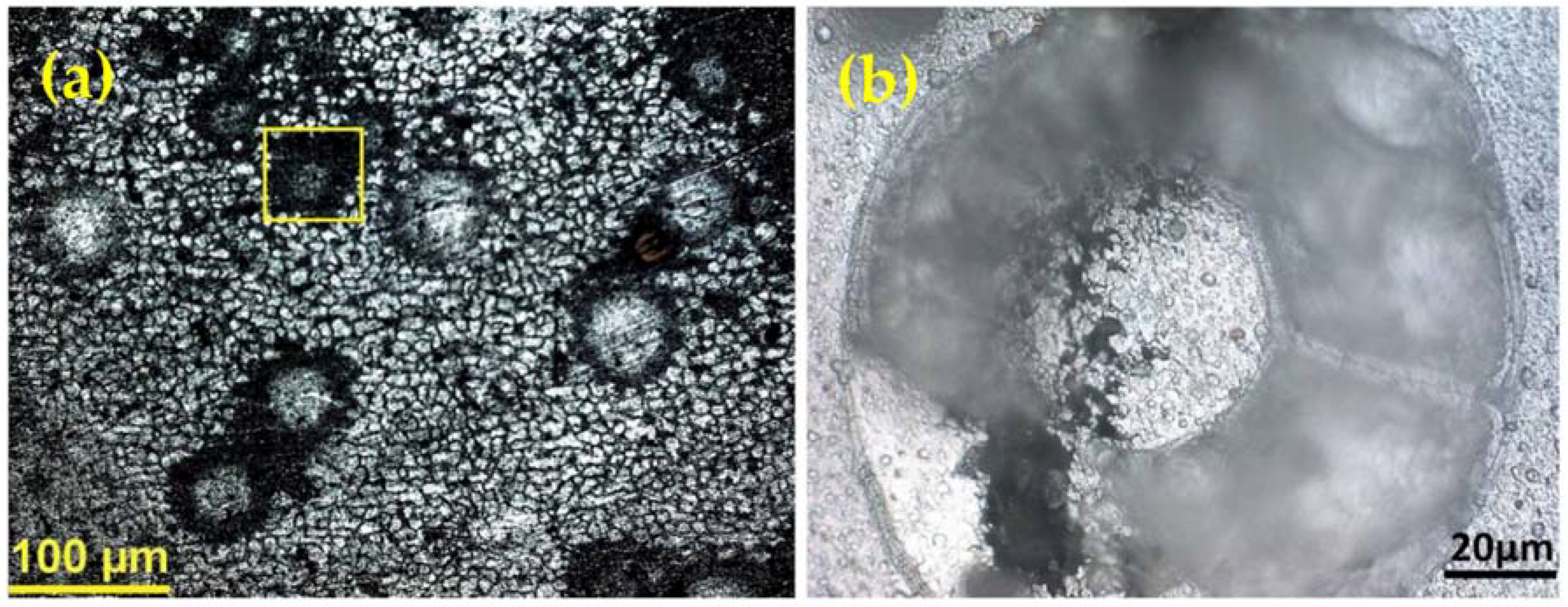
The other consequence of the thermomechanical processing of the polycrystalline structure is related to the S.Z microstructure. As Figure 6a reveals, the fine-grained homogenized structure of the S.Z, some uncommon blister-like stain patterns are visible within the weld region, near the surface. At first glance, these might be misdiagnosed as over-etching artefacts or impurity particles, but this is unlikely, as they are an integral part of the microstructure. They are unlikely to be precipitates, as their size is larger than normal. This is not pitting, as the structure is filled rather than an open void expected of a pit. It is also not an inclusion, as these appear in identifiably different ways for this alloy [20]. Figure 6b shows a higher magnification of this segregated spherical mass within the S.Z. Our interpretation is that these granular areas comprise the amorphous structure of metallic-glass. The blurred microscopic region has a glassy/amorphous structure with a central shrinkage core in the middle of the sphere. This is typical of the formation of amorphous phase comprising a local shrinkage and lattice mismatch with the crystalline lattice [36,37,38,39]. Hence, we propose that an element of localized melting has occurred, with a fast cooling rate. This is consistent with the observed superficial location of these structures, where proximity to air may cause faster cooling, though cooling rates were not measured.
Most alloys have a crystalline lattice structure in their solid-state structures with a long-ordered arrangement of atoms. Sometimes, after thermal processing, when the cooling rate is non-equilibrium, there is not enough time for crystals to form, and the mass is locked in a glassy state. In this situation, the result is an amorphous or non-crystalline metal structure with a disordered atomic-scale structure or glass-like structure. There are occasional reports in the literature of a process in which a metallic-glass structure was formed by the FSW technique. This is observable as an amorphous layer formed by a self-propagating reaction due to the mechanical alloying effects [40,41,42,43]. The present results (Figure 6) show multiple amorphous regions that are distinct from the polycrystalline texture of the stirring zone. As mentioned above, it is believed that these are amorphous glass-metal features.
The structures were observed in only one of the weld samples. However, the process conditions under which this occurs are unknown. The structures have a random distribution in the sub-shoulder region. As evident in Figure 6a, the structures are separate from each other. They have an average grain size of 50 μm.
The spherical structure appeared after etching, and were best observed when etchant D was used. As the polished samples utilized for the electron microscopy were not etched, observation of these structures by SEM was not possible during our analysis. Hence, there was no chance to identify the composition of these patterns. Hence the composition is uncertain—a comprehensive diagnosis would require transmission electron microscopy and Raman spectroscopy (XRD is unsuitable, as it is inherently for crystalline structures), but these methods were beyond the present scope. It is not impossible that an Al2O3 composition may be involved. One possible origin could be from the broken surface oxide layer entering into the weld. It may be relevant to note that these structures were considerably larger than those observed in the literature [40,41].
That concludes the results of the optical microscopy. Next, we provide more precise evidence for grain refinement details using electron microscopy and EBSD.
3.2. Electron Microscopy
3.2.1. Dynamic Recrystallization
Figure 7 demonstrates the comparative EBSD maps of the B.M and S.Z regions showing different grain size and morphology. The drawn patterns based on the crystallographic measurement of the microstructure confirm that the directional large grains of the B.M. have converted to the fine grains structure of the S.Z with a spherical morphology. The average grain size of the S.Z region is less than 10 μm, while the B.M grains are in the range of 100 μm. Similar to the optical micrographs, these features confirm the dynamic recrystallization condition along with successful grain refinement during the thermo-mechanical regime experienced in the BFSW process. The dark features present in the material are attributed to the position of sites which could not be crystallographically detected by EBSD mapping. These features may be representative of porosity formed in primary rolling processing of AA6082-T6 plates. However, the S.Z microstructure shows that after BFSW processing, the number and size of these features are reduced (at the same magnification). This implies an increase of the structure’s density across the deformed grains, as the BFSW thermomechanical process—comprising forging and extrusion—can fragment the grains, squeeze the plasticized mass within the fixed gap between shoulders, and provide a condensed texture with decrease in grain size.
We tentatively attribute the dark features to porosity, but there are other possible interpretations. We can exclude a pitting effect of the etchants because the surface was a micropolished specimen without any etching. However, EBSD is sensitive to micro-cracks and micro-voids, as these defects can interrupt the diffraction of backscattered arrays from the surface, hence can leave dark features. So the features may be cracks or voids of origin other than casting porosity. The fact that they become reduced in extent after welding implies they are micro-voids or porosity.
3.2.2. Precipitation
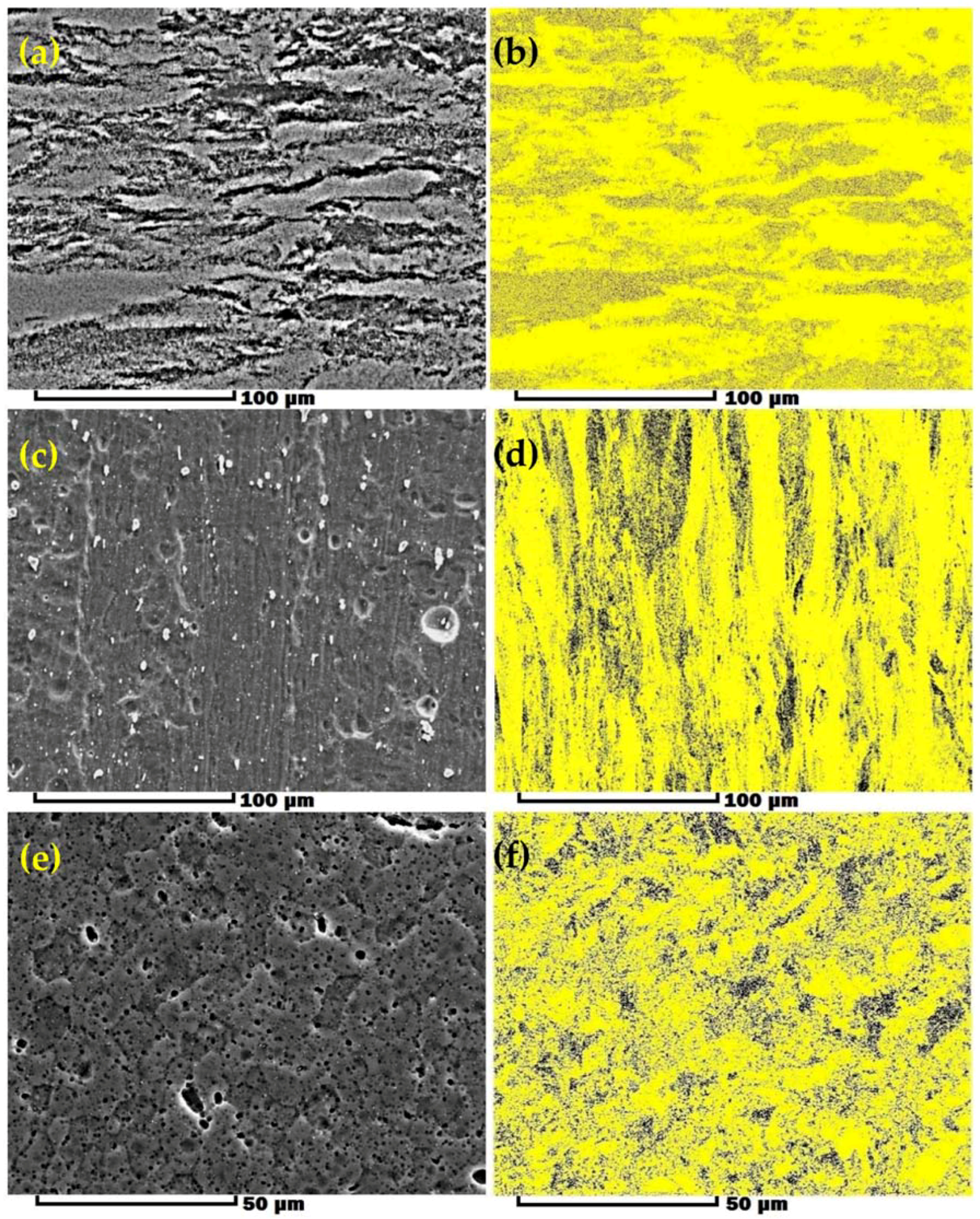
Another subject that requires explanation is precipitation (nucleation, spatial distribution and morphology) in the BFSW weld structure. Using optical microscopy, we observed some fine dotted patterns within the grains (Figure 3, Figure 4 and Figure 5). However, there was no conclusive evidence to determine whether they were precipitates or pitting stains. Pitting stains emerge by over-etching. Figure 8 reveals the results of secondary electrons (SE) imaging and their corresponding phase color contrasting maps for different regions of weld (B.M, TMAZ and S.Z). The phase map distinguishes the Al matrix phase as the yellow background, from dark spots representative of the secondary precipitate phase. Secondary electrons (SE) imaging is a beneficial analysis for the inspection of the topography of the sample surface. As shown in Figure 8a–c, micrographs delineate a wrinkled structure that is representative of the work-hardening and recovery mechanisms during the thermomechanical process. Similarly, the phase maps show that the density of precipitates is enhanced from the B.M towards the center of the weld (S.Z), as the thermomechanical effects of the process (shear stress, strain and temperature) become intensified. Figure 8c,d shows that round features apparent in Secondary electron imaging (SEI, Figure 8c) are not evident in the phase map (Figure 8d). We conclude that that the round features evident in the optical microscopy (see Figure 4) are pits rather than precipitates.
In general, artificial ageing and T6 precipitation in the stabilized microstructure of AA6082-T6 needs a higher temperature and longer time in the furnace, compared to the BFSW process. It appears that here the precipitation mechanism has been activated by the thermomechanical work. On the other hand, as the grain size is reducing from B.M towards the S.Z (see Figure 8), the precipitation density increases. Precipitates have a pinning effect which restricts the grain boundaries. Hence, it is inferred that the reduction in grain size is primarily a result in the increased density of precipitates. This is consistent with the literature [44].
The thermomechanical behavior of the material has conflicting effects on precipitation. First, the shear induced by the severe plastic deformation and the consequent grain fragmentation activate the precipitate nucleation, probably by providing more preferred crystallographic sites for nuclei. Second, the thermal effect causes dissolution of the primary precipitates in the original substrate material, but also forms new secondary precipitates during the recrystallization. These secondary precipitates are stabilized by the stored strain at cooling. The overall outcome of all these mechanisms facilitates the occurrence of precipitation during the thermomechanical process.
The phase color contrasting map shows the distribution of the precipitates through different regions of the weld during the BFSW process. Different phases of precipitates can be analyzed by the EDS elemental map. In general, the Al-Mg-Si alloy system has two main precipitate phases: Mg-Si and Al-Mg-Si. The sequence of precipitation is generally recognized to follow this route:
Super-Saturated Solid Solution (SSSS) → Mg/Si Clusters → GP-Zone (GPZ) → β″-Mg5Si6 → β′-Mg9Si5 → β-Mg2Si [45].
The Guinier Preston Zone (GPZ) is a fine-scale metallurgically transitional phenomenon, comprising early stage precipitation where the first metastable phases of precipitates can be characterized. For the Al-Mg-Si systems, U1-Al2MgSi2, U2-Al4Mg4Si4 and B′-Al3Mg9Si7 are the most common metastable GPZ precipitates constrained in an Al matrix. Later, however, these metastable phases are resolved to result in β″and β′ as the stoichiometry compositions of the terminal β-phase.
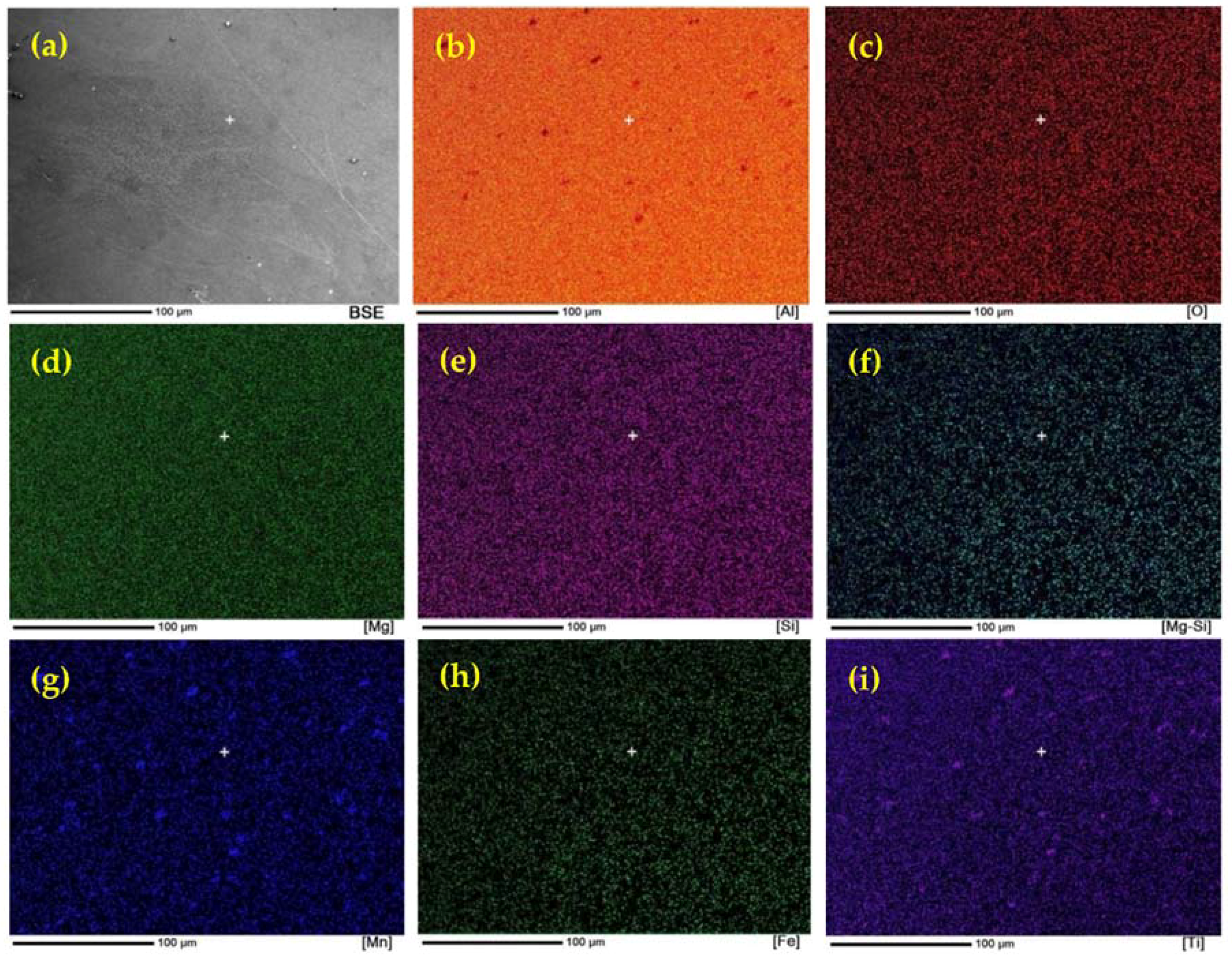
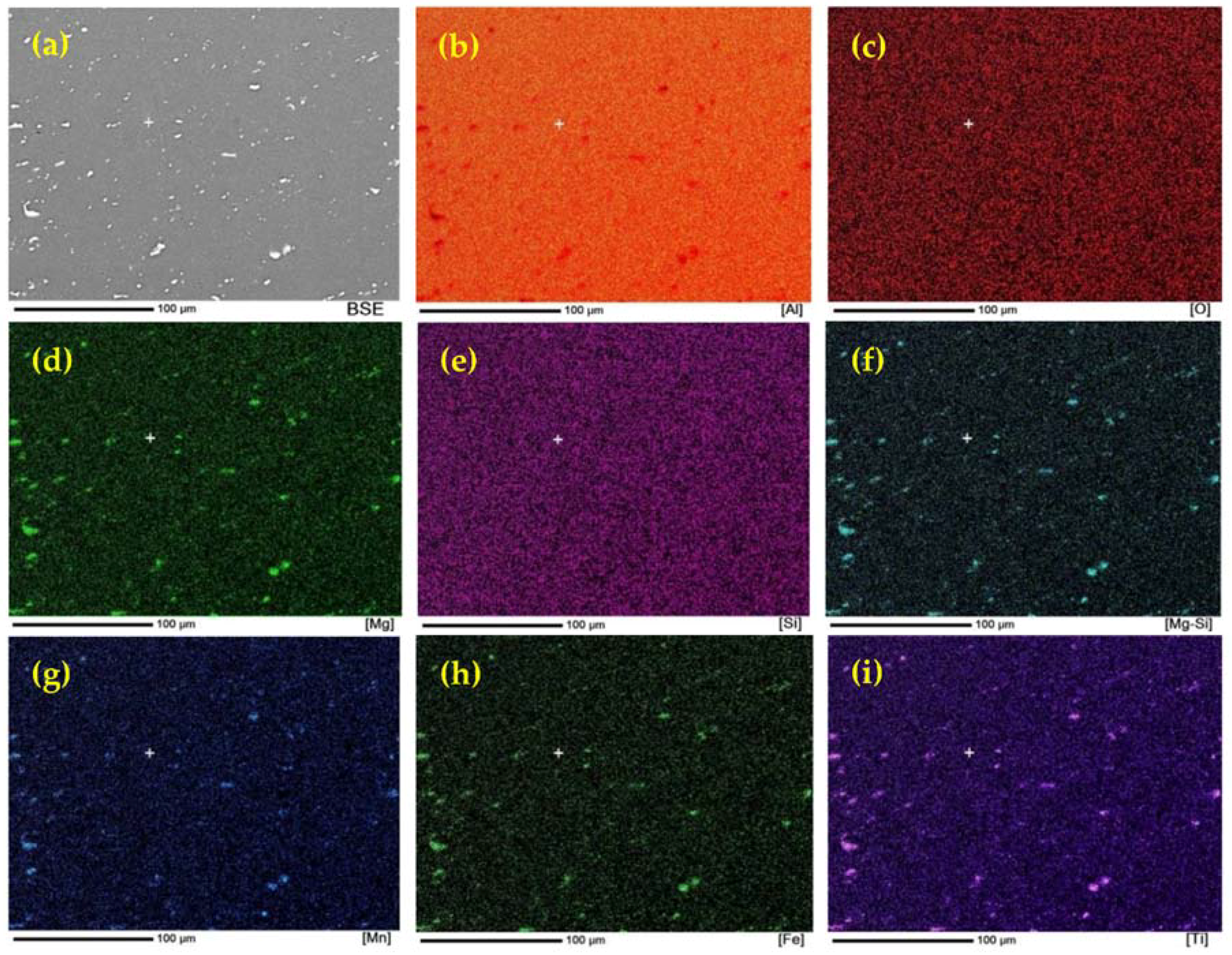
To reveal how the precipitates were spatially and morphologically distributed in the B.M and S.Z of weld region, elemental map observations of the cross-sectional microstructure of the AA6082-T6 joints were carried out. Figure 9 and Figure 10 show the Back Scattered Electron (BSE) image and corresponding in situ elemental distributions from EDS mapping of the constituents/phases for the cross section of AA6082-T6 weld sample before and after BFSW processing. The colorful area in each image represents the respective elemental distribution. For both figures, the back-scattered electrons (BSE) imaging for the analyzed regions is also present. BSE imaging can provide a more detailed observation of the surface, so the spatial distribution of the spherical-like precipitates phase can be seen to be distinctively different in morphology from the underlying matrix. The results show that the alloying elements are uniformly composed and distributed in the structures, as there is no large contrast in element maps. Also, in both B.M and S.Z regions, there is no sign of the presence of oxygen in EDS maps. This proves the alloy elements have not reacted with air during the process. Comparison of the EDS maps also reveals that during the T6 ageing cycle only a few precipitations are visible, while in the processed S.Z region the number of the precipitates grains is increased. It shows that thermomechanical BFSW process is effective in activation of the phase transformation and precipitation of the secondary phase.
The chemical composition of AA6082-T6 contains alloy elements additional to Al-Mg-Si (e.g., Mn, Ti and Fe), hence it can form different precipitates in addition or instead of the major β phase. As can be seen in Figure 9a, in the Al matrix of the B.M, a limited number of fine particles is distributed over long distances from each other with the average size being under 5 μm (white particles). The EDS map of B.M (Figure 9b–i) shows a contrast in composition for Mn and Ti containing maps which indicates that precipitate particles are rich in elements Mn and Ti. According to the Al-Ti-Mn ternary phase diagram it can be expect that the γ-based TiAl2Mn composition was formed as precipitate particles. The fine TiAl2Mn crystals were formed in the condition of supersaturated crystallization in Al-based solid solution under T6 tempering. The artificially aged condition of the T6 cycle supplies the driving force for TiAl2Mn nucleation to form within the crystal. Therefore, in the B.M microstructure, the supersaturated lattice contains a number of fine precipitates.
Compared to the B.M, the S.Z showed a higher density of white particles of 10 μm average size (Figure 10a). Similarly, the EDS element mapping measurement reveal a contrast in distribution of particles in the Al-based background as shown in Figure 10b–i. Compared with the B.M, the elemental maps of the S.Z reveal that in addition to the presence of Mn and Ti, the precipitates contain Mg, Si and Fe. We attribute this change in elements to the heat input generated during the FSW process causing dissolving and recrystallization of precipitates in the S.Z. At the higher temperatures during stirring, the γ–based precipitates dissolved gradually and resulted in an Al-phase supersaturated solid solution. Due to the thermodynamic stability of the microstructure, secondary precipitate crystallization occurs during the cooling. Non-equilibrium heat generation and cooling, and the stored strain in the structure during stirring, are proposed as the driving forces of nucleation. This also activates new crystal orientations; thereby, other elements (Fe, Si and Mg) can take part in the composition of the precipitates crystal lattice to form a variety of β and γ phase families. Furthermore, heat preservation during stirring can result in coarsening of the recrystallized precipitates where it formed larger-sized particles of 10 μm average size. These uniformly distributed larger precipitates play a key role in disruption of the migration of the grain boundary which leads to the strengthening mechanism during the welding process.
4. Discussion
4.1. Model for Strengthening Mechanism
The grain refinement occurred in a solid-state thermomechanical process with the same content of element composition of the alloy, without any external refiner. The performance comparison of this thermomechanical grain refinement was made in marine-grade AA6082-T6 aluminum, in which the T6 microstructure is changed during the BFSW process. The grain microstructure comparison of the aluminum phase confirms the conversion of coarse columnar grains to fine equiaxed grains through the BFSW process. This leads to an increase of the G.B density, which can consequently act as blocking features in front of dislocations and improve the strength of the structure. Also, EBSD studies reveal precipitation nucleation that is uniformly distributed in the Al matrix over the whole processed area. This can have a double positive effect on the grain refinement result by activation of the strengthening mechanism using hardening particles with a pinning effect on dislocation movement.
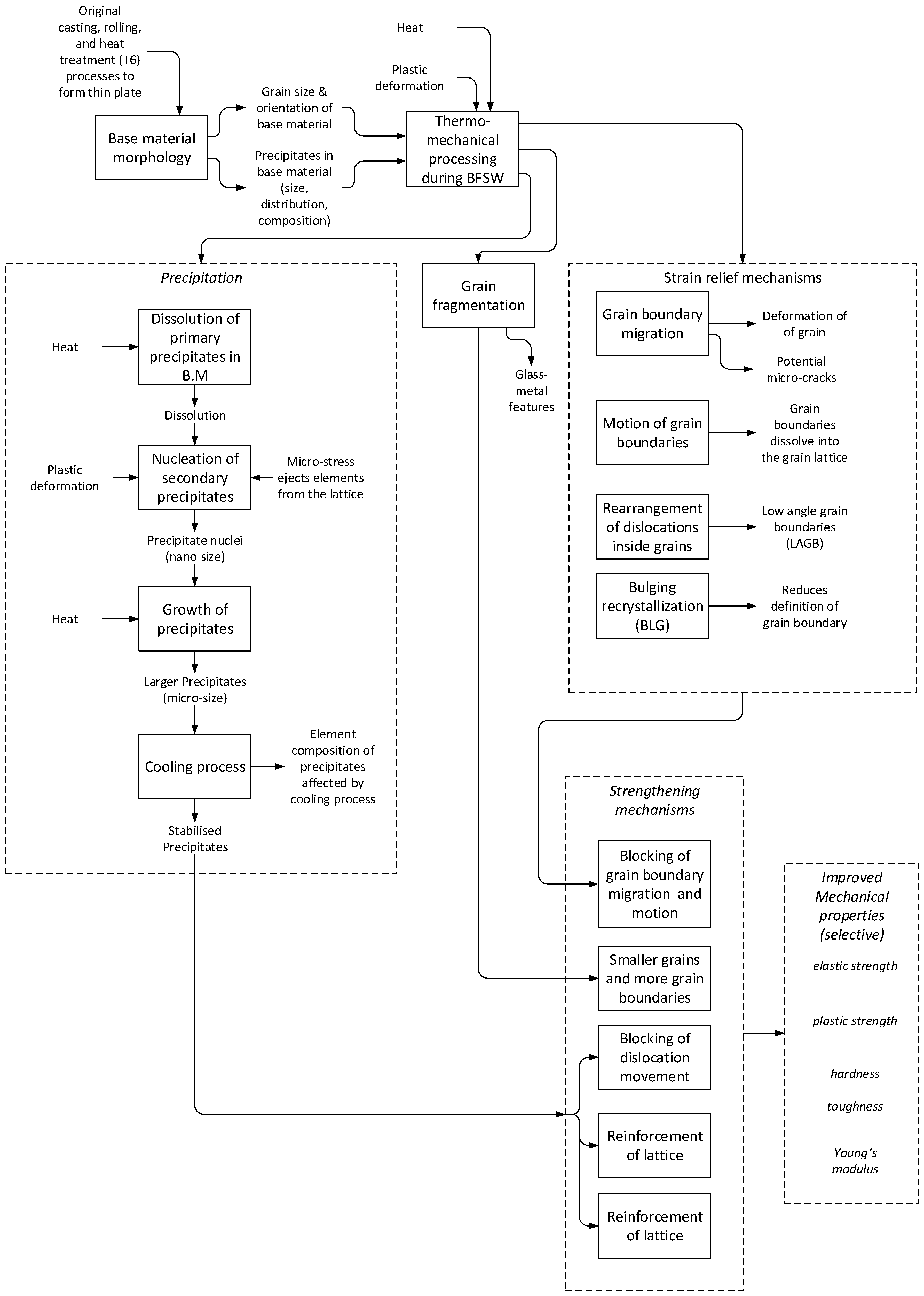
A number of mechanisms have been identified for grain refinement, as illustrated through optical and electron microscopy. We identify several pathways whereby the thermomechanical process of BFSW contribute to the strengthening of the weld material, and ultimately to improved mechanical properties of the weld. These provide self-healing effects, which counter the mechanisms that cause failure (such as micro-cracks). These beneficial mechanisms are precipitation, grain fragmentation, and strain relief mechanisms.
We propose that the improved mechanical properties are selective, in that not all of strength, hardness, toughness, etc., can be simultaneously optimized. The balance between different features of the microstructure determine these macroscopic properties in ways that are not fully quantified. We summarize the effects and their interactions in Figure 11. The details of these processes are described above.
4.2. Original Contributions
Key findings are the identification of specific changes in grain size and precipitation. We identified physical evidence for motion of grain boundaries, bulging recrystallization, grain boundary migration, and low-angle grain boundaries (sub-grain boundaries). These effects are attributed to the thermomechanical nature of this welding process. Glass-metal features were identified in the stirring zone, and these are evidence of localized melting and rapid cooling.
4.3. Implications for Practitioners
For those using AA6082-T6, e.g., in maritime construction, the implications are that processes should be directed to production of the precipitates and changing of the microstructure during the welding process. BFSW offers the potential for in situ grain refinement and recovery of mechanical properties. However this material can be difficult to weld, in that a number of flow-based defects can occur, such as tunnel defects [25,27] and hence the tool design and the process settings can be critical.
4.4. Limitations and Implications for Future Research
This study was limited to the quantitative description of the grain refinement features induced by the thermomechanical behavior of the BFSW process. Possible further advancements might be achieved by measurement of the heat generation and the stored strain induced by the plastic deformation. A possible line of future investigation may be directed to extracting the weld texture measurement via the Kernel Average Misorientation (KAM) or the Grain Orientation Spread (GOS) analysis to see how thermomechanical features of the BFSW can affect the grain refinement phenomenon.
The accurate composition and percentage of each phase was not determined here, and would require X-ray diffraction (XRD) or quantitative mass spectrometry measurements, which could be a subject for further research. However, what can be said is that the EBSD method shows the distribution of the secondary phase/precipitates, using the phase color mapping for the B.M and S.Z regions. The XRD phase analysis and the EDS mass analysis for the element composition of precipitate particles can reveal the accurate composition and quantity fraction of different nucleated phases before and after precipitation. This can provide a more accurate clarification for the efficiency of the refining process.
5. Conclusions
The microstructural evolution of AA6082-T6 BFSW weld plate was analyzed using optical microscopy and EBSD tests. It was possible to measure grain size, recrystallization and grain-boundary, precipitates spatial distribution character. Both optical and EBSD micrographs show a significant grain refinement with a change in grain morphology from directional columnar in B.M to ultrafine equiaxed morphology in S.Z. The qualitative aspects of the thermomechanical processing (BLG, GBM and SGBs/LAGBs features) were also studied in the TMAZ region. Additionally, the microscopic studies of the S.Z introduced a spherical microstructure that resembles the metallic-glass phase. EBSD results consisting of phase mapping and EDS elemental maps provided strong evidence for the existence of precipitate phases which are nucleated and remained with a uniform distribution in the deformed structure of the BFSW weld.
Author Contributions
The material science component of the study was designed by A.T., the welding was conducted by K.S., sample preparation and microscopy were performed by A.T., metallurgical findings were established by A.T. and refined in discussion with D.J.P., the model was developed by A.T. and D.J.P., the first draft of the paper was written by A.T., all authors contributed to editing the paper, with final edits by A.T. and D.J.P., supervision by D.J.P., D.C., K.S.
Acknowledgments
Thanks are extended to Mike Flaws and Kevin Stobbs for assistance with electron and optical microscopy respectively.
Conflicts of Interest
The authors declare no conflict of interest.
References
- Thomas, W. Friction Stir Welding. International Patent Application No PCT/GB92/02203, 6 December 1991. [Google Scholar]
- Thomas, W.; Wiesner, C. Recent developments of FSW technologies: Evaluation of root defects, composite refractory tools for steel joining and one-pass welding of thick sections using self-reacting bobbin tools. In Proceedings of the 8th International Conference Trends in Welding Research, Callaway Gardens Resort, Pine Mountain, GA, USA, 1–6 June 2008; ASM International: Almere, The Netherlands, 2009; p. 25. [Google Scholar]
- Thomas, W.; Wiesner, C.; Marks, D.; Staines, D. Conventional and bobbin friction stir welding of 12% chromium alloy steel using composite refractory tool materials. Sci. Technol. Weld. Join. 2009, 14, 247–253. [Google Scholar] [CrossRef]
- Threadgill, P.L.; Ahmed, M.; Martin, J.P.; Perrett, J.G.; Wynne, B.P. The Use of Bobbin Tools for Friction Stir Welding of Aluminium Alloys; Materials Science Forum; Trans Tech Publication: Zürich, Switzerland, 2010; pp. 1179–1184. [Google Scholar]
- Myhr, O.; Klokkehaug, S.; Grong, O.; Fjær, H.; Kluken, A. Modeling of microstructure evolution, residual stresses and distortions in 6082-T6 aluminum weldments. Weld. J. N. Y. 1998, 77, 286-s. [Google Scholar]
- McNelley, T.; Swaminathan, S.; Su, J. Recrystallization mechanisms during friction stir welding/processing of aluminum alloys. Scr. Mater. 2008, 58, 349–354. [Google Scholar] [CrossRef] [Green Version]
- Nandan, R.; DebRoy, T.; Bhadeshia, H. Recent advances in friction-stir welding–process, weldment structure and properties. Prog. Mater. Sci. 2008, 53, 980–1023. [Google Scholar] [CrossRef]
- Russell, M.; Shercliff, H. Analytical modelling of microstructure development in friction stir welding. In Proceedings of the 1st International Symposium On Friction Stir Welding, Oaks, CA, USA, 14–16 June 1999. [Google Scholar]
- Schmidt, H.; Hattel, J. A local model for the thermomechanical conditions in friction stir welding. Model. Simul. Mater. Sci. Eng. 2004, 13, 77. [Google Scholar] [CrossRef]
- Nandan, R.; Roy, G.; Debroy, T. Numerical simulation of three-dimensional heat transfer and plastic flow during friction stir welding. Metall. Mater. Trans. A 2006, 37, 1247–1259. [Google Scholar] [CrossRef]
- Thomas, W.; Nicholas, E. Friction stir welding for the transportation industries. Mater. Des. 1997, 18, 269–273. [Google Scholar] [CrossRef]
- Sued, M.; Pons, D.; Lavroff, J. Compression ratio effects in bobbin friction stir welding. In Proceedings of the 10th International Friction Stir Welding Symposium, Beijing, China, 20–22 May 2014; pp. 1–19. [Google Scholar]
- Sued, M.K.; Pons, D.J. Dynamic interaction between machine, tool, and substrate in bobbin friction stir welding. Int. J. Manuf. Eng. 2016, 2016, 8697453. [Google Scholar] [CrossRef]
- Song, M.; Kovacevic, R. Thermal modeling of friction stir welding in a moving coordinate system and its validation. Int. J. Mach. Tools Manuf. 2003, 43, 605–615. [Google Scholar] [CrossRef]
- Sofuoglu, H.; Rasty, J. Flow behavior of plasticine used in physical modeling of metal forming processes. Tribol. Int. 2000, 33, 523–529. [Google Scholar] [CrossRef]
- Kumar, K.; Kailas, S.V. The role of friction stir welding tool on material flow and weld formation. Mater. Sci. Eng. A 2008, 485, 367–374. [Google Scholar] [CrossRef]
- Sued, M.K. Fixed Bobbin Friction Stir Welding of Marine Grade Aluminium. Ph.D. Thesis, University of Canterbury, Christchurch, New Zealand, 2015. [Google Scholar]
- Babu, G.R.; Murti, K.; Janardhana, G.R. An experimental study on the effect of welding parameters on mechanical and microstructural properties of aa 6082-T6 friction stir welded butt joints. ARPN J. Eng. Appl. Sci. 2008, 3, 68–74. [Google Scholar]
- Seidel, T.; Reynolds, A.P. Two-dimensional friction stir welding process model based on fluid mechanics. Sci. Technol. Weld. Join. 2003, 8, 175–183. [Google Scholar] [CrossRef]
- Tamadon, A.; Pons, D.J.; Sued, K.; Clucas, D. Development of metallographic etchants for the microstructure evolution of A6082-T6 BFSW welds. Metals 2017, 7, 423. [Google Scholar] [CrossRef]
- Sued, M.; Tamadon, A.; Pons, D. Material flow visualization in bobbin friction stir welding by analogue model. Proc. Mech. Eng. Res. Day 2017, 2017, 368–369. [Google Scholar]
- Vander Voort, G.; Manilova, E.P. Metallographic Etching of Aluminum and Its Alloys; Buehler Ltd., EUA: Lake Bluff, IL USA, 2009. [Google Scholar]
- Sasabe, S.; Matsumoto, T. Mechanical properties of A6082 welded joints with ND–yag laser. Weld. Int. 2012, 26, 351–359. [Google Scholar] [CrossRef]
- Schneider, J.; Nunes, A.C., Jr. Origins of Line Defects in Self-Reacting Friction Stir Welds and Their Impact on Weld Quality; NASA Marshall Space Flight Center: Huntsville, AL, USA, 2016.
- Tamadon, A.; Pons, D.J.; Sued, K.; Clucas, D. Formation mechanisms for entry and exit defects in bobbin friction stir welding. Metals 2018, 8, 33. [Google Scholar] [CrossRef]
- Xu, H.; Tang, H.; Liu, Z.; Xie, M.; Jiao, J. Microstructure and mechanical properties of 6082 aluminum alloy joints welded by MIG. Hot Work. Technol. 2010, 1, 42. [Google Scholar]
- Sued, M.; Pons, D.; Lavroff, J.; Wong, E.-H. Design features for bobbin friction stir welding tools: Development of a conceptual model linking the underlying physics to the production process. Mater. Des. (1980–2015) 2014, 54, 632–643. [Google Scholar] [CrossRef]
- Jata, K.; Semiatin, S. Continuous Dynamic Recrystallization during Friction stIr Welding of High Strength Aluminum Alloys; Air Force Research Lab Wright-Patterson AFB OH Materials and Manufacturing Directorate: Dayton, OH, USA, 2000. [Google Scholar]
- Waldron, D.J.; Roberts, R.W.; Dawes, C.J.; Tubby, P.J. Friction Stir Welding—A Revolutionary New Joining Method; SAE International: Warrendale, PA, USA, 1998. [Google Scholar]
- Zhang, H.; Wang, M.; Zhang, X.; Yang, G. Microstructural characteristics and mechanical properties of bobbin tool friction stir welded 2A14-T6 aluminum alloy. Mater. Des. (1980–2015) 2015, 65, 559–566. [Google Scholar] [CrossRef]
- Fonda, R.; Bingert, J. Precipitation and grain refinement in a 2195 Al friction stir weld. Metall. Mater. Trans. A 2006, 37, 3593–3604. [Google Scholar] [CrossRef]
- Fonda, R.; Bingert, J.; Colligan, K. Development of grain structure during friction stir welding. Scr. Mater. 2004, 51, 243–248. [Google Scholar] [CrossRef]
- Vander Voort, G.F.; Lampman, S.R.; Sanders, B.R.; Anton, G.J.; Polakowski, C.; Kinson, J.; Muldoon, K.; Henry, S.D.; Scott, W.W., Jr. Metallography and Microstructures. In ASM Handbook; ASM International: Almere, The Netherlands, 2004; Volume 9, pp. 40002–44073. [Google Scholar]
- Tamadon, A.; Ds, K.C.; Pons, D.; Sued, M.; Clucas, D.; Wong, E. Analogue modelling of bobbin tool friction stir welding. In Proceedings of the International Conference on Innovative Design and Manufacturing, Auckland, New Zealand, 14–16 September 2016. [Google Scholar]
- Czubayko, U.; Sursaeva, V.; Gottstein, G.; Shvindlerman, L. Influence of triple junctions on grain boundary motion. Acta Mater. 1998, 46, 5863–5871. [Google Scholar] [CrossRef]
- Wang, D.; Xiao, B.; Ma, Z.; Zhang, H. Friction stir welding of Zr55Cu30Al10Ni5 bulk metallic glass to Al–Zn–Mg–Cu alloy. Scr. Mater. 2009, 60, 112–115. [Google Scholar] [CrossRef]
- Fujii, H.; Sun, Y.; Inada, K.; Ji, Y.; Yokoyama, Y.; Kimura, H.; Inoue, A. Fabrication of Fe-based metallic glass particle reinforced Al-based composite materials by friction stir processing. Mater. Trans. 2011, 52, 1634–1640. [Google Scholar] [CrossRef]
- Sun, Y.; Ji, Y.; Fujii, H.; Nakata, K.; Nogi, K. Microstructure and mechanical properties of friction stir welded joint of Zr55Cu30Al10Ni5 bulk metallic glass with pure copper. Mater. Sci. Eng. A 2010, 527, 3427–3432. [Google Scholar] [CrossRef]
- Li, F.; Zhang, D.; Luo, Z.; Tan, C.; Lin, J. Microstructure and mechanical properties of friction stir welded joint of Zr46Cu46Al8 bulk metallic glass with pure aluminum. Mater. Sci. Eng. A 2013, 588, 196–200. [Google Scholar] [CrossRef]
- Sato, Y.S.; Yamashita, F.; Sugiura, Y.; Park, S.H.C.; Kokawa, H. Fib-assisted tem study of an oxide array in the root of a friction stir welded aluminium alloy. Scr. Mater. 2004, 50, 365–369. [Google Scholar] [CrossRef]
- Sato, Y.S.; Takauchi, H.; Park, S.H.C.; Kokawa, H. Characteristics of the kissing-bond in friction stir welded Al alloy 1050. Mater. Sci. Eng. A 2005, 405, 333–338. [Google Scholar] [CrossRef]
- Kobata, J.; Takigawa, Y.; Chung, S.; Tsuda, H.; Kimura, H.; Higashi, K. Nanoscale amorphous “band-like” structure induced by friction stir processing in Zr55Cu30Al10Ni5 bulk metallic glass. Mater. Lett. 2007, 61, 3771–3773. [Google Scholar] [CrossRef]
- Ogura, T.; Saito, Y.; Nishida, T.; Nishida, H.; Yoshida, T.; Omichi, N.; Fujimoto, M.; Hirose, A. Partitioning evaluation of mechanical properties and the interfacial microstructure in a friction stir welded aluminum alloy/stainless steel lap joint. Scr. Mater. 2012, 66, 531–534. [Google Scholar] [CrossRef]
- Zipperian, D.C. Metallographic Handbook; Chief Technical Officier PACE Technologies: Tucson, AZ, USA, 2011. [Google Scholar]
- Frøseth, A.G.; Høier, R.; Derlet, P.M.; Andersen, S.J.; Marioara, C.D. Bonding in mgsi and Al-Mg-Si compounds relevant to Al-Mg-Si alloys. Phys. Rev. B 2003, 67, 224106. [Google Scholar] [CrossRef]
Figure 1.
Schematic of transverse cross-section of the BFSW weld; dynamic interaction between bobbin tool and AA6082-T6 butted substrate during the stirring. The dotted lines denote the location of the hourglass borders as the inherent feature of the BFSW weld. The red arrows are representative of the compression ratio and the consequent axial forging force generated by stirring.

Figure 2.
Configuration of the bobbin tool utilized for the AA6082-T6 weld trial.

Figure 3.
Microstructure of different regions of a BFSW A6082-T6 weld, processed by etchant A. (a) B.M, the yellow arrows show the motion of G.B; (b) S.Z; (c) Heat Affected Zone (HAZ); (d) Thermo-mechanical Affected Zone (TMAZ).
Figure 3.
Microstructure of different regions of a BFSW A6082-T6 weld, processed by etchant A. (a) B.M, the yellow arrows show the motion of G.B; (b) S.Z; (c) Heat Affected Zone (HAZ); (d) Thermo-mechanical Affected Zone (TMAZ).

Figure 4.
Morphological transition of grain flow in the TMAZ processed by etchant: (a) overview; (b) higher magnification view of the region closer to the heat affected zone; (c) higher magnification view of the region closer to the stirring zone.
Figure 4.
Morphological transition of grain flow in the TMAZ processed by etchant: (a) overview; (b) higher magnification view of the region closer to the heat affected zone; (c) higher magnification view of the region closer to the stirring zone.

Figure 5.
Thermomechanical features in TMAZ region, processed by etchant C. (a) Grain Boundary Migration (the location is highlighted by the white arrows); (b) Subgrain Boundaries (yellow arrows).
Figure 5.
Thermomechanical features in TMAZ region, processed by etchant C. (a) Grain Boundary Migration (the location is highlighted by the white arrows); (b) Subgrain Boundaries (yellow arrows).

Figure 6.
(a) Spherical blister-like stains within the microstructure of S.Z, processed by etchant D; (b) Magnified feature of the blister-like patter, revealing a structure similar to the metallic-glass phase. The yellow rectangle shows the progressive area of magnification from (a) to (b). These features are interpreted as evidence of localized amorphous structure.

Figure 7.
EBSD patterns of the phase map for: (a) B.M and (b) S.Z, and (c,d) their respective grain distribution histograms.
Figure 7.
EBSD patterns of the phase map for: (a) B.M and (b) S.Z, and (c,d) their respective grain distribution histograms.

Figure 8.
Secondary electron imaging (SEI) of different region of the weld and the relevant phase mappings. (a,b) B.M; (c,d) TMAZ; (e,f) S.Z.
Figure 8.
Secondary electron imaging (SEI) of different region of the weld and the relevant phase mappings. (a,b) B.M; (c,d) TMAZ; (e,f) S.Z.

Figure 9.
Elemental EDS map of the AA6082-T6 microstructure at B.M. (a) BSE image and corresponding distribution of (b) Al; (c) O; (d) Mg; (e) Si; (f) Mg-Si; (g) Mn; (h) Fe; and (i) Ti elements.
Figure 9.
Elemental EDS map of the AA6082-T6 microstructure at B.M. (a) BSE image and corresponding distribution of (b) Al; (c) O; (d) Mg; (e) Si; (f) Mg-Si; (g) Mn; (h) Fe; and (i) Ti elements.

Figure 10.
Elemental EDS map of the AA6082-T6 BFSW weld at the S.Z. (a) BSE image and corresponding distribution of (b) Al; (c) O; (d) Mg; (e) Si; (f) Mg-Si; (g) Mn; (h) Fe; and (i) Ti elements.
Figure 10.
Elemental EDS map of the AA6082-T6 BFSW weld at the S.Z. (a) BSE image and corresponding distribution of (b) Al; (c) O; (d) Mg; (e) Si; (f) Mg-Si; (g) Mn; (h) Fe; and (i) Ti elements.

Figure 11.
Model of the causal mechanisms whereby thermomechanical processing causes grain refinement and, hence, improved mechanical properties.
Figure 11.
Model of the causal mechanisms whereby thermomechanical processing causes grain refinement and, hence, improved mechanical properties.


Table 1.
Element composition of the AA6082 Al alloy (wt. %) [33].
Table 1.
Element composition of the AA6082 Al alloy (wt. %) [33].
| AA6082-T6 | Composition |
|---|---|
| Chemical Element | % Present |
| Silicon (Si) | (0.70–1.30) |
| Magnesium (Mg) | (0.60–1.20) |
| Manganese (Mn) | (0.40–1.00) |
| Iron (Fe) | (0.0–0.50) |
| Chromium (Cr) | (0.0–0.25) |
| Zinc (Zn) | (0.0–0.20) |
| Titanium (Ti) | (0.0–0.10) |
| Copper (Cu) | (0.0–0.10) |
| Other (Each) | (0.0–0.05) |
| Other (total) | (0.0–0.15) |
| Aluminium (Al) | Balance |
Table 2.
Parameters of the BFSW (Bobbin friction stir welding) trial for the AA6082-T6 plates.
| Welding Parameters | Amount |
|---|---|
| DShoulder (mm) | 21 |
| DPin (mm) | 7 |
| DShoulder/DPin | 3 |
| Plate Thickness (mm) | 4 |
| Compression Ratio | 3.75% |
| Spindle rotational speed, ω (rpm) | 600 |
| Feed rate, V (mm/min) | 400 |
| Thread Pitch (mm) | 1 |
| Number of Threads | 4 |
Table 3.
Different chemical solutions for etching with separate processing procedures.
| Name of Etchant | Pre-Etching | Etchant Composition |
|---|---|---|
| A | - | 0.5 g (NH4)2MoO4 + 3.0 g NH4Cl + 1 mL HF + 18 mL HNO3 + 80 mL H2O (90 s, 70 °C) |
| B | 20 g NaOH + 80 mL H2O (20 s, 50 °C), | Etchant A (60 s, 70 °C) |
| C | 20 g NaOH + 80 mL H2O (20 s, 50 °C), then: 30 mL H3PO4 + 70 mL ethanol (20 s, 50 °C) | 10 g CrO3 + 2 g Na2SO4 + 10 mL HNO3 + 10 mL CH3COOH + 1 mL HF + 80 mL H2O (60 s, 70 °C) |
| D | 20 g NaOH + 80 mL H2O (20 s, 50 °C), then: 30 mL H3PO4 + 70 mL ethanol (20 s, 50 °C) | Etchant C (60 s, 70 °C), then: 15 mL CH3COOH + 85 mL H2O (15 s, 70 °C), then: 15 mL H3PO4 + 85 mL H2O (15 s, 70 °C) |
© 2018 by the authors. Licensee MDPI, Basel, Switzerland. This article is an open access article distributed under the terms and conditions of the Creative Commons Attribution (CC BY) license (http://creativecommons.org/licenses/by/4.0/).
Share and Cite
MDPI and ACS Style
Tamadon, A.; Pons, D.J.; Sued, K.; Clucas, D. Thermomechanical Grain Refinement in AA6082-T6 Thin Plates under Bobbin Friction Stir Welding. Metals 2018, 8, 375. https://0-doi-org.brum.beds.ac.uk/10.3390/met8060375
AMA Style
Tamadon A, Pons DJ, Sued K, Clucas D. Thermomechanical Grain Refinement in AA6082-T6 Thin Plates under Bobbin Friction Stir Welding. Metals. 2018; 8(6):375. https://0-doi-org.brum.beds.ac.uk/10.3390/met8060375
Chicago/Turabian StyleTamadon, Abbas, Dirk J. Pons, Kamil Sued, and Don Clucas. 2018. "Thermomechanical Grain Refinement in AA6082-T6 Thin Plates under Bobbin Friction Stir Welding" Metals 8, no. 6: 375. https://0-doi-org.brum.beds.ac.uk/10.3390/met8060375
Note that from the first issue of 2016, this journal uses article numbers instead of page numbers. See further details here.