Effect of the Tool Tilt Angle on the Heat Generation and the Material Flow in Friction Stir Welding


International Center for Numerical Methods in Engineering (CIMNE), Technical University of Catalonia, Campus Norte UPC, 08034 Barcelona, Spain
*
Author to whom correspondence should be addressed.
Metals 2019, 9(1), 28; https://0-doi-org.brum.beds.ac.uk/10.3390/met9010028
Submission received: 5 December 2018
/
Revised: 20 December 2018
/
Accepted: 24 December 2018
/
Published: 29 December 2018
(This article belongs to the Special Issue Friction Stir Welding and Processing in Alloy Manufacturing)
Abstract
:This work studies the effect of the tool tilt angle on the generated heat and the material flow in the work pieces joint by Friction Stir Welding (FSW). An apropos kinematic framework together with a two-stage speed-up strategy is adopted to simulate the FSW problem. The effect of tilt angle on the FSWelds is modeled through the contact condition by modifying an enhanced friction model. A rotated friction shear stress is proposed, the angle of rotation depending on the process parameters and the tilt angle. The proposed rotation angle is calibrated by the experimental data provided for a tilt angle 2.5°. The differences of generated heat and material flow for the cases of tool with tilt angle of 0° and 2.5° are discussed. It is concluded that due to the higher temperature, softer material and greater frictional force in the trailing side of the tool, the material flow in the rear side of the FSW tool with the title angle is considerably enhanced, which assists to prevent the generation of defect.
1. Introduction
Friction Stir Welding (FSW) uses a tool with a high rotating speed which moves forward between the pieces to be joined and generates heat. The main function of the tool (consisting of pin and shoulder) is to mix the work piece material and to generate heat by friction. The final properties of friction stir welds depend on factors such as the process parameters (advancing and rotating speed), the tool design and the tool tilt angle [1,2,3]. In previous works, the authors have studied the effects of the tool velocity [4] and the tool design [5]. In this work, the effect of the tool tilt angle is addressed.
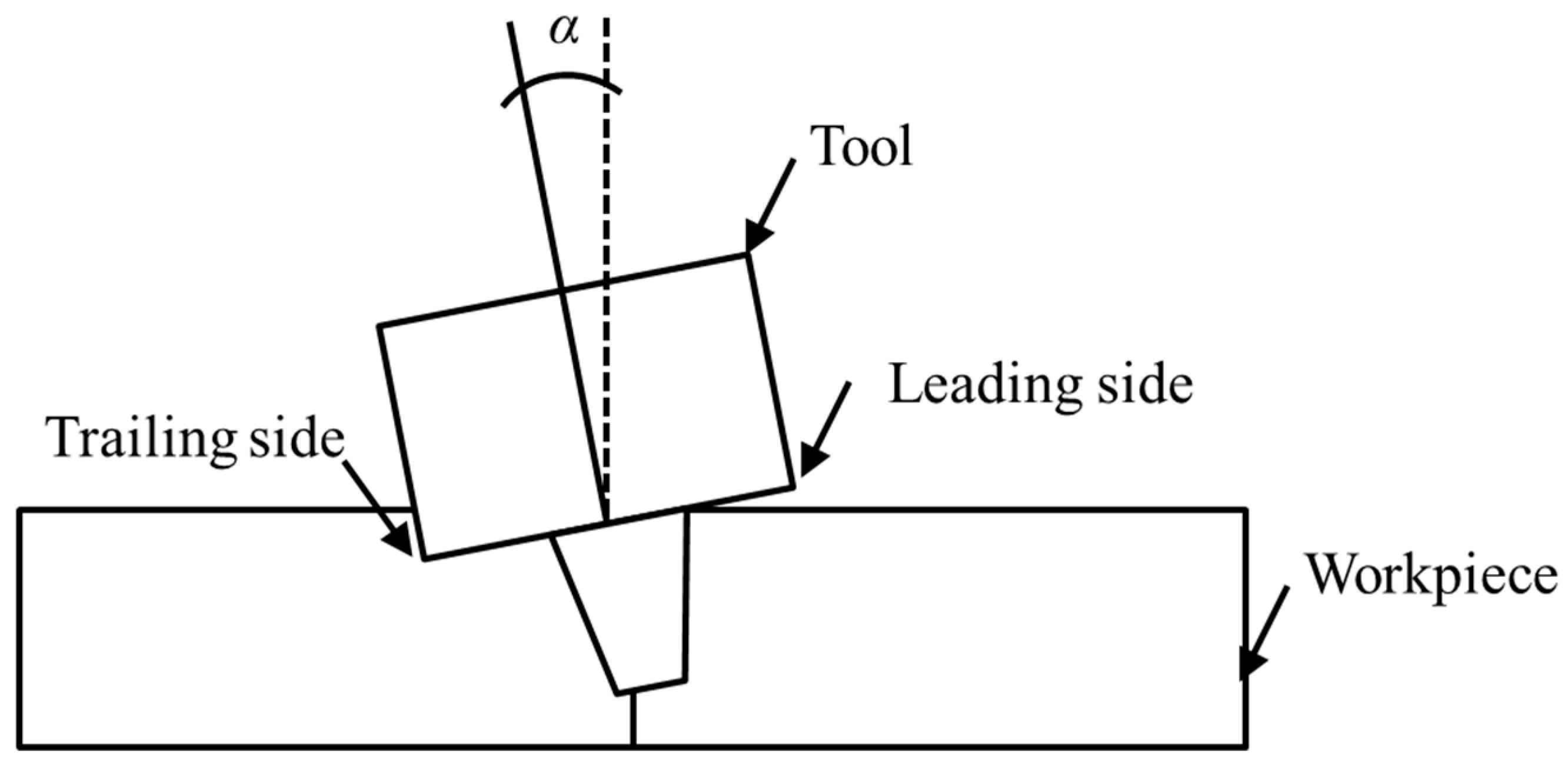
Figure 1 presents a cross-sectional view of an (exaggeratedly) tilted tool inside the work piece. Typical tilt angles used in practice are between 0° and 3°, where a zero value signifies that the tool is perpendicular to the work piece. The tool tilt angle affects the material flow during the weld and thus the heat generation. In FSW, the heat is generated by friction and plastic dissipation. As the mechanical properties are notably temperature-dependent, material flow and heat generation are dependent on each other, making FSW a strongly coupled thermo-mechanical problem. The tool tilt angle has a fundamental importance for the weld quality in FSW. On the one hand, a non-zero tilt angle ensures the contact among the tool shoulder and the work piece; moreover, it facilitates the flow of the material around the tool. On the other hand, an inadequately large tilt angle raises the pin from the weld root, resulting in damaged welds. Consequently, it is essential to properly choose the tool tilt angle. An optimal tool tilt angle guarantees that the tool shoulder imprisons the deformed material and transports it proficiently from the front edge to the rear side of the pin [6].
The tilt angle of the tool and its noticeable effect on the final post-weld quality has been studied by several investigators [7,8,9]. These studies show that the tool tilt angle has a significant effect on the formation of defects during the weld. The optimal tool tilt angle facilitates the material flow around the tool and avoids the formation of defects in the weld zone. Several experimental tests have to be performed to obtain the optimal tilt angle. However, the fundamental mechanism of the tilt effect on heat generation and material flow is yet to be understood.
Reshad et al. [10] study the effects of the tool tilt angle on FSW of pure titanium. They considered several test cases where the tool tilt angle is varied and the effect of this variation on the post-weld properties is examined. They obtained 1° as the best tilt angle for a defect-free welding with high mechanical properties.
Banik et al. [11] examine weld qualities of FSW AA6061-T6 from the point of view of the final mechanical properties of the work piece by changing the tool tilt angles for taper featureless and taper threaded tools. They observe that an increase of the tool tilt angle increases the forces and the torque at the tool/work piece interface.
Elyasi et al. [12] study the effect of the tilt angle on FSW of dissimilar alloys (aluminum to steel). Tilt angles of 1°, 2° and 3° are chosen. They observe that a larger tilt angle increases the axial force and the interaction between aluminum and steel.
Hamid and Roslee [13] investigate the tilt angle effect on microstructural and mechanical characteristics of FSWelded dissimilar aluminum alloys. They observe that the tilt angle affects the mechanical properties of the FSW joints considerably. Microstructure of the weld also changes significantly by varying the tilt angle, specifically in the area of weld nugget and heat affected zone.
Meshram and Reddy [14] study the role of the tilt angle on defects generation and material flow in FSW. They observe that the variation of tool tilt angle changes the thermo-mechanical results during FSW and therefore alters the material flow in the weld and controls the weld defects.
In spite of the importance of the effect that the tool tilt angle has on the final quality of the welded work piece, there are only a few computational studies of this phenomenon. Numerical simulations may provide detailed knowledge of the process from both thermal and mechanical point of views.
Long et al. [15] present a 3D thermo-mechanical model with a non-zero tilt angle and study its effect on the final joint. They use DEFORM-3D to simulate the FSW process in a Lagrangian framework. In their work, the tilt angle is considered inside of the geometrical model. They test two cases of 0° and 2° tilt angle. Wormhole defects are observed in case of 0°, while the weld in case of 2° is defect free.
Chauhan et al. [16] investigate the effect of three tilt angles (0°, 1° and 2°) on the formation of defects in FSW applying a Coupled Eulerian and Lagrangian (CEL) method. They use ABAQUS/Explicit to model FSW process with a cylindrical pin. In order to avoid the serious mesh distortion encountered when modeling FSW, the work piece is defined as a Eulerian body. Their model predicts that a tilt angle of 2° produces a defect free weld.
Aghajani Derazkola and Simchi [17] present experimental and numerical analysis of friction stir welding of poly (methyl methacrylate) work pieces. They study the effect of process parameters such as tilt angle to define the appropriate conditions for seeking defect-free joints. They observe that the tool tilt angle affects the material flow around the tool. The applied downward forging force needs to be increased for increasing tilt angles, and this results in more frictional heat generation.
There are forecast models based on Artificial Neural Network (ANN). In these cases, both experimental and numerical data are collected to correlate process parameters with technical features of the welded joint. Hamilton et al. [18] integrate differential scanning calorimetry curves for 2017A and 7075 in an existing computational model of the FSW process for heat generation and material flow to create the phase transformations maps occurring in the weld zone. The tool tilt angle of 1.5 is considered during the process. They observe that close to the weld tool, the processing temperatures dissolve fully the equilibrium phase in 7075 and partially in 2017A. Casalino et al. [19] implement ANN in order to investigate the effects of process parameters on the laser welding process quality. Using statistical estimation, the relevance of the process parameters with the weld geometry is studied. It is demonstrated that ANN modeling is beneficial for optimizing the quality of manufacturing processes. Pathak and Jaiswal [20] provide a review on the applications of ANN in FSW. They consider the tilt angle as one of the controlling factor. They conclude that ANN results are matching with the experimental data.
From the previous works, it can be concluded that the tilt angle has a significant effect on the heat generation and material flow and is a controlling parameter to produce a defect free joint.
In previous works devoted to the numerical modeling of the effect of the tilt angle, this angle was considered in the geometrical setting, but not in the contact condition at the tool/work piece interface. Reference [21] is one of the few works, both experimental and numerical, to address heat and mass transfer due to the tilt angle. They use an Eulerian framework for an axisymmetric pin and an incomplete contact boundary condition that applies frictional tangential force on a contact area defined based on the tilt angle (α) and an in plane rotating angle (β) of the contact area. From the experimental evidence, they conclude that this in plane rotating angle is 45° and they use it in the numerical analysis.
In this work, we address the numerical analysis of the effect of the tool tilt angle on FSW from the computational approach developed previously by the authors [5]. It allows obtaining the steady state rapidly at the speed-up phase of the simulation. This is followed by a periodic stage simulation, assuming the first stage as the initial condition. An apropos kinematic system is used by mixing Arbitrary Lagrangian Eulerian (ALE), Eulerian and Lagrangian schemes for different areas of the computational model. The framework can accommodate any pin shapes.
The influence of the tilting is to be represented by the enhanced friction model accounting for the effect of non-uniform pressure distribution under the tool and tilting. The friction model is modified by introducing an in plane rotating angle (β) which depends on the tool tilt angle (α) and the advancing and rotating velocities. In the current study, this parameter is calibrated from the temperature field obtained experimentally for the tilt angle 2.5° presented in reference [21]. Alternatively, the rotating angle β can be obtained experimentally from the relationship between the longitudinal and the transversal forces exerted on the tool.
The outline of this paper is as follows. In Section 2, the general solution strategy used in this work is explained. In Section 3 the modified friction model considering the effect of the tilt angle is presented and discussed. The last section is devoted to the analysis of tool tilt angle effect on the thermo-mechanical behavior in FSW. Mechanical results including the material flow are presented and compared for the no tilt (α = 0°, β = 0°) and with tilt (α = 2.5°, β = 25°) cases. Lastly, some conclusions are drawn.
2. Solution Strategy
The simulation of FSW can be performed in different kinematic frameworks: Lagrangian, Eulerian and ALE.
In a Lagrangian framework, material moves together with the reference system. Therefore, the material flow during the weld is the direct solution of the problem. However, due to the large material deformation in the stir zone of FSW, the mesh used in this area requires continuous re-meshing during the simulation. Re-meshing introduces a significant computational overhead and re-interpolation errors. Thus, the application of other kinematic frameworks is more attractive.
In an Eulerian framework the movement of the material is defined on a fixed configuration. Therefore, no re-meshing is needed. This framework presents limitations when non axisymmetric tool pin shapes are modeled. In these cases, the boundaries of the model are constantly changing by the rotation of the tool pin. Thus re-characterization of the integration domain at every time step of the analysis is indispensable.
The alternative to Lagrangian and Eulerian approaches is an ALE framework where the reference system is not fixed and allowed to move independently from the material movement. An ALE framework permits to treat arbitrary pin geometries and re-meshing can be avoided using a mesh around the tool that rotates rigidly together with the tool.
In a Lagrangian framework, the tool tilt angle can be directly included in the geometrical modeling. In the Eulerian and ALE frameworks, the geometrical model can include the tool tilt angle directly only if the pin shape is axisymmetric. Tilted non-axisymmetric pin shapes require specific ALE approaches [22] as the rotation of the tool is not synchronized with the rotation of the mesh around the tool.
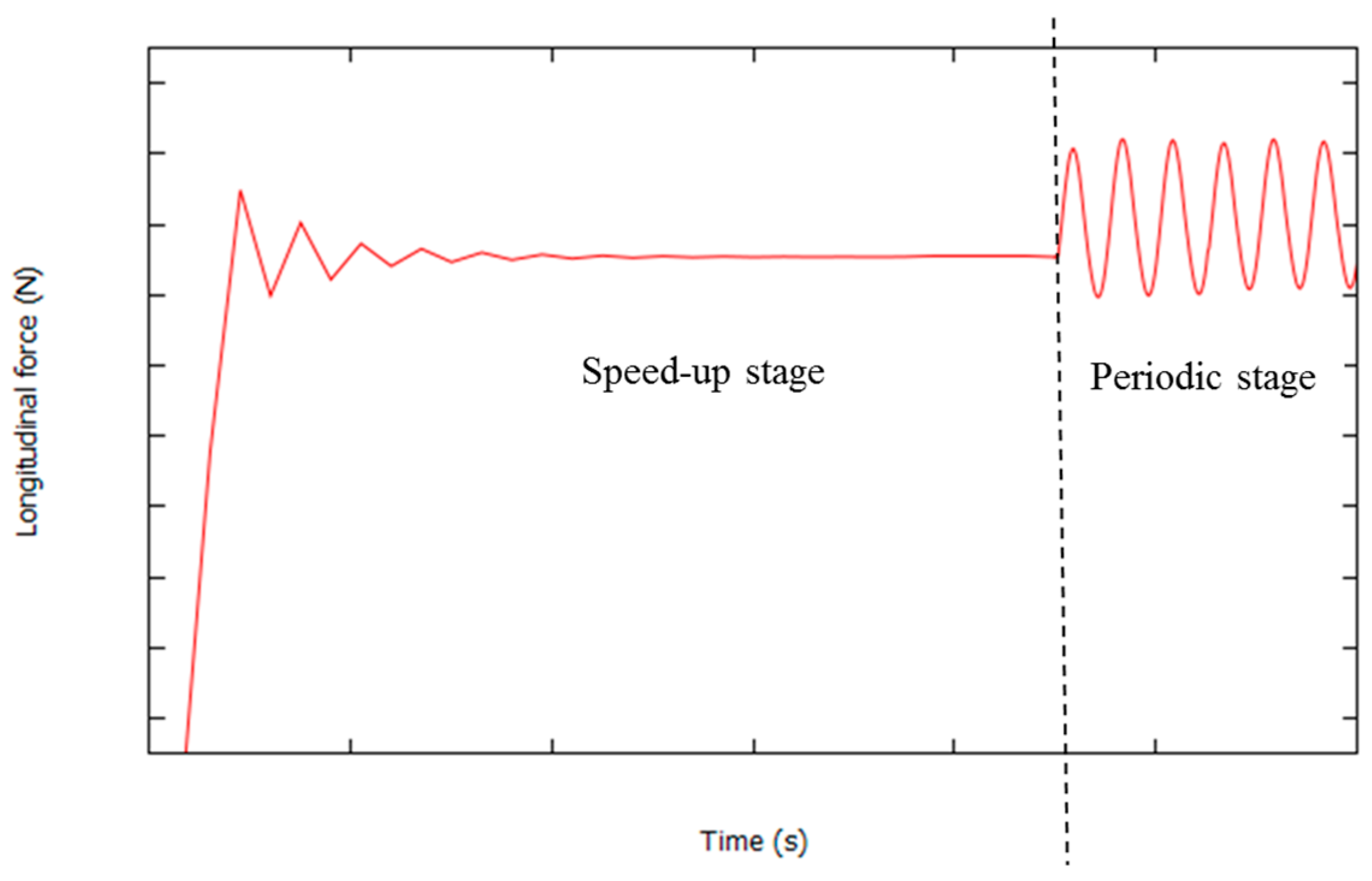
In this work a feasible kinematic framework and a two-stage (speed-up and periodic stages) strategy are adopted for the solution of the overall problem [5,23] (Figure 2). The strategy uses a fully coupled thermo-mechanical framework at both stages. The solution of the coupled thermo-mechanical problem is acquired by performing a staggered time-stepping algorithm solving the thermal and mechanical sub-problems sequentially for each time step.
The speed-up stage aims at obtaining the steady state rapidly by modifying the thermal inertia term in the energy balance equation. At this stage an Eulerian formulation is used.
The periodic stage considers the results obtained at the first stage as an initial condition. At this stage an apropos kinematic framework is used [23]. The choice of this framework is for combining the benefits of ALE, Eulerian and Lagrangian formulations by applying them in the stir zone, the remains of the work piece and the pin-tool, respectively.
The main effect of the tilt angle on the process behavior is the heat generation and its influence on the material flow during FSW. As the sources of heat generation in FSW are plastic dissipation and friction, the suitable modification of the friction law is the strategy proposed here in order to include the effect of the tilt angle.
All the implementations used for this work are done in the in-house finite element code COMET [24] developed by the authors. Details on the technical and computational aspects of the formulation are given in the references [5,23,25].
The resulting model incorporates a two-stage strategy that can speed up the transient stage to obtain the periodic stage with 50 times reduced computational costs comparing with the standard models [5]. Moreover, the model is enriched with an enhanced friction model that considers the real process behavior for generating the frictional heat and can consider the effect of the tilt angle in the heat generation and material flow.
3. Friction Model Including the Tilt Angle
The friction law describes the contact condition at the interface between the tool and the work piece as indicated by their relative sliding velocities. Coulomb’s [26,27,28,29] and Norton’s [22] friction laws are regularly utilized in FSW simulation.
In the previous work of the authors [30], a modified Norton’s law is proposed considering the non-uniform pressure distribution that is generally found under the tool during FSW. The enhanced friction model defines the friction shear stress at each point at the contact surface as
where is the friction shear stress, is the sliding velocity, 0 ≤ q ≤ 1 is the sensitivity parameter, x is the location of each point at the tool/work piece contact surface relative to the rotation axis projected on the welding direction and R is the shoulder radius. and are the maximum and the minimum friction tractions. Figure 3 presents a schematic view of this distribution of friction traction where the average value of the friction is at the center of the tool (x = 0). Note that the and values are attained at the leading and trailing edges of the shoulder.
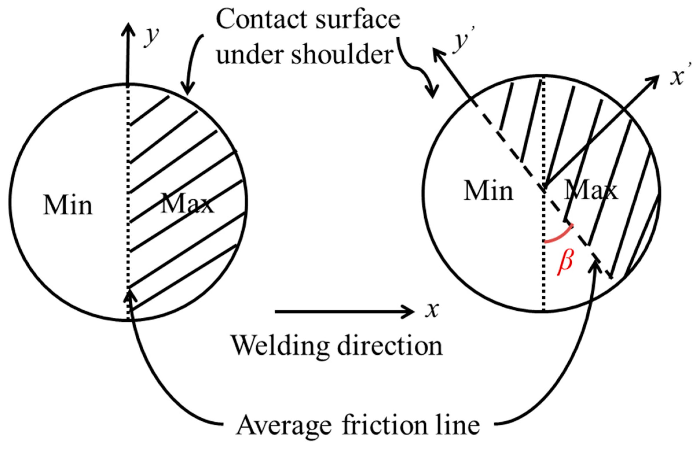
This friction law in Equation (1) does not take into account the effect of the tilt angle. In case of having a tilt angle α (backwards), as the FSW tool advances in the weld direction, the contact surface that has a maximum friction value in front of the tool and minimum friction in the rear side rotates a certain angle β (counterclockwise) around the (counterclockwise) rotating axis due to the tilt influence [21]. This is detected from the experimental evidence in the reference [21] where the effect of tilting appears on the rotation of the contact print. Figure 4 shows schematically what is observed in the experiments. Therefore, the maximum friction is not at the front side but it is rotated by an angle β. The tilting of the tool results in the subsequent rotation of the average friction line. Figure 5 shows schematically how the distribution of the friction under the shoulder is affected by the tool tilt. The x-axis is along the welding direction with or without tilt angle; it is perpendicular to the average friction line (y-axis) when no tilt angle exists. For a tilt angle α, the average friction line (y’-axis) is rotated an angle β in the horizontal plane.
The angle β of the friction shear stress distribution depends on the welding parameters such as tilt angle α, rotating speed ω and advancing speed vadv:
In this work, angle β is obtained by calibration from the temperature field of the experiment presented in [21]. However, the rotating angle β can be obtained experimentally from the relationship between the longitudinal (Fx) and the transversal (Fy) forces exerted on the tool.
The detailed numerical investigation and its experimental validation of the dependence of angle β on the process parameters are out of the scope of this work. We will focus on the influence of angle β on the thermo-mechanical behavior of FSW, by comparing two cases: without tilt (α = 0°, β = 0°) and with tilt (α = 2.5°, β = 25°).
Considering the effect of the tilt and the rotation of the contact shear stress between the tool and the work piece, the reference axes x and y are rotated to the new position x’ and y’.
where β is the rotating angle of the contact surface. Therefore, Equation (1) can be rewritten as
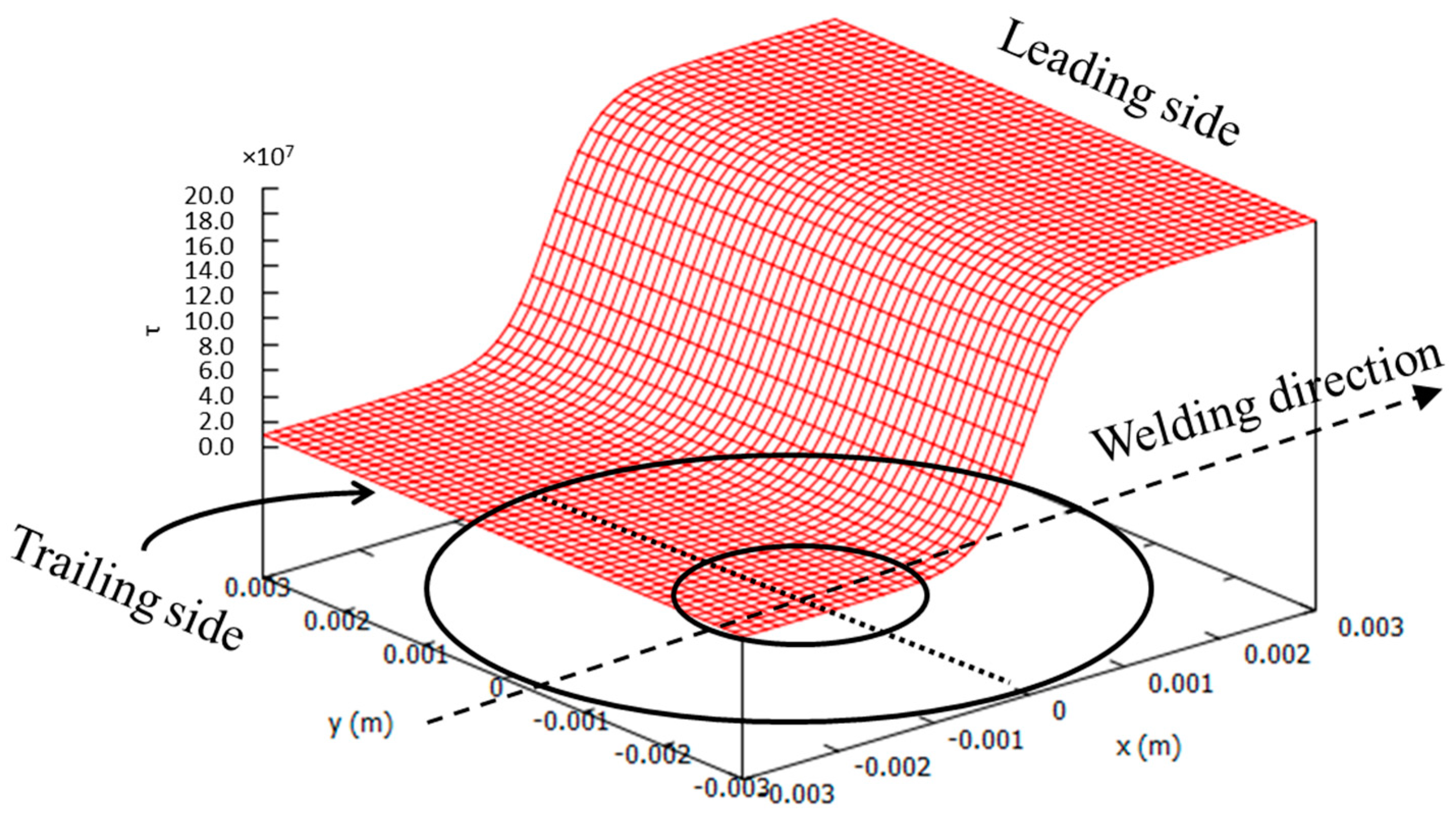
Figure 6 presents the distribution of friction law in case of having a tilt angle. The average value of the friction is rotated around the center of the tool.
4. Analysis of the Effect of the Tilt Angle
In this section, the effect of the tool tilt angle on the thermo-mechanical results of a FSW simulation is studied. The thermal effects are studied through the temperature field. The mechanical effects are analyzed via velocity, stress and strain rate fields and material flow around the tool.
Two cases are considered: 0° and 2.5° tilting angle. The two cases are identical from the point of view of material, processing parameters, geometry and they only differ in tilt angle.
The temperature field in case of having tilt angle obtained from numerical analysis is compared with experiment [21] in order to obtain the corresponding angle of rotation β. Then the thermo-mechanical results in both cases of with and without tilt angle are compared against each other.
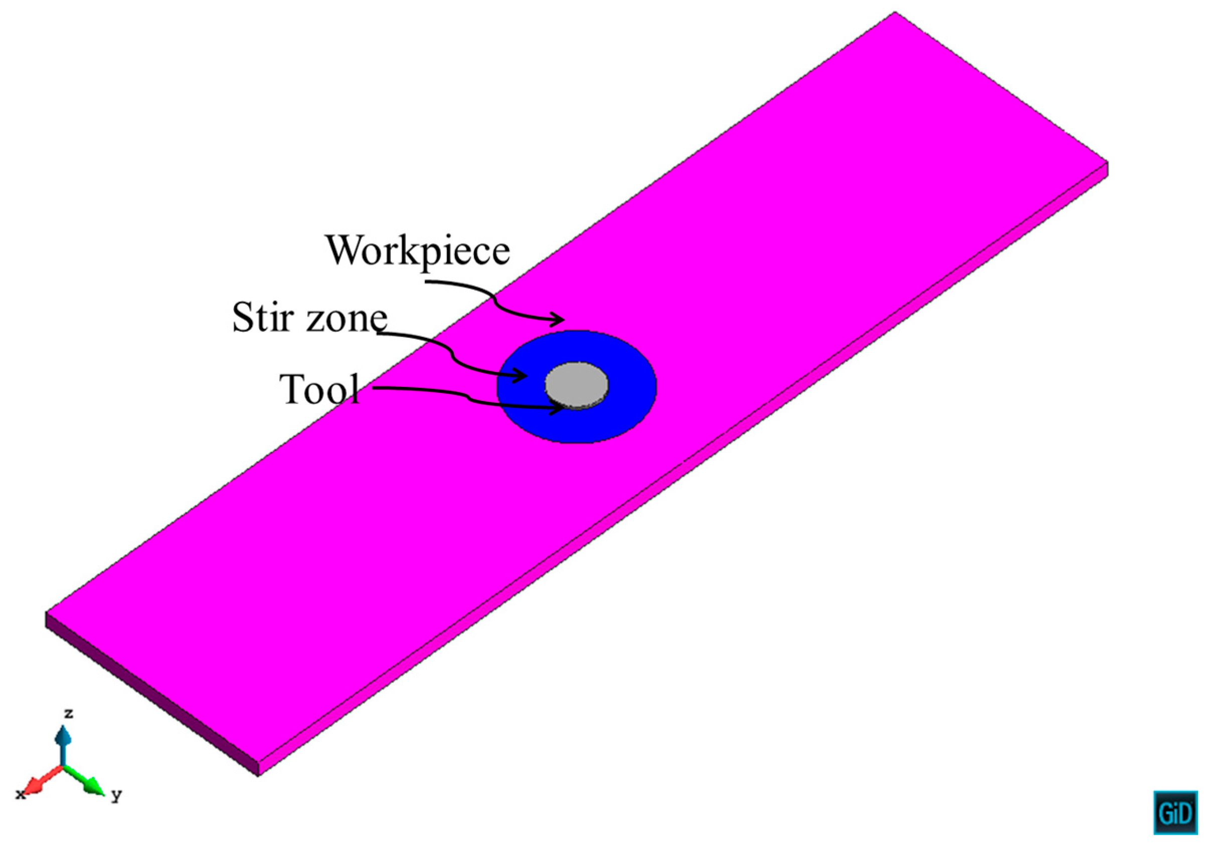
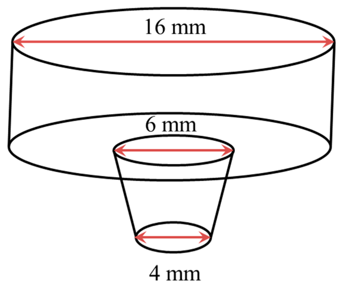
The material selected is aluminum alloy AA2024-T4. The chemical composition (wt%) of the aluminum alloy AA2024-T4 is Cu = 4.53, Mg = 1.62, Mn = 0.65, Si = 0.066, Fe = 0.21 and Al = Bal. [31]. The dimension of the work piece is 300 × 75 × 5 mm3. Figure 7 shows the geometry model including tool, stir zone and the rest of the work piece. The tool has a flat shoulder of 16 mm diameter and a featureless conical pin. The top and bottom diameter of the pin are 6 mm and 4 mm, respectively. The height of the pin is 4.8 mm. Figure 8 shows the dimension of the tool used.
The rotating and advancing velocities are 800 rpm and 20 mm/min, respectively.
The process parameters are selected as such to compare the numerical results obtained in this work with the experimental data published in [21].
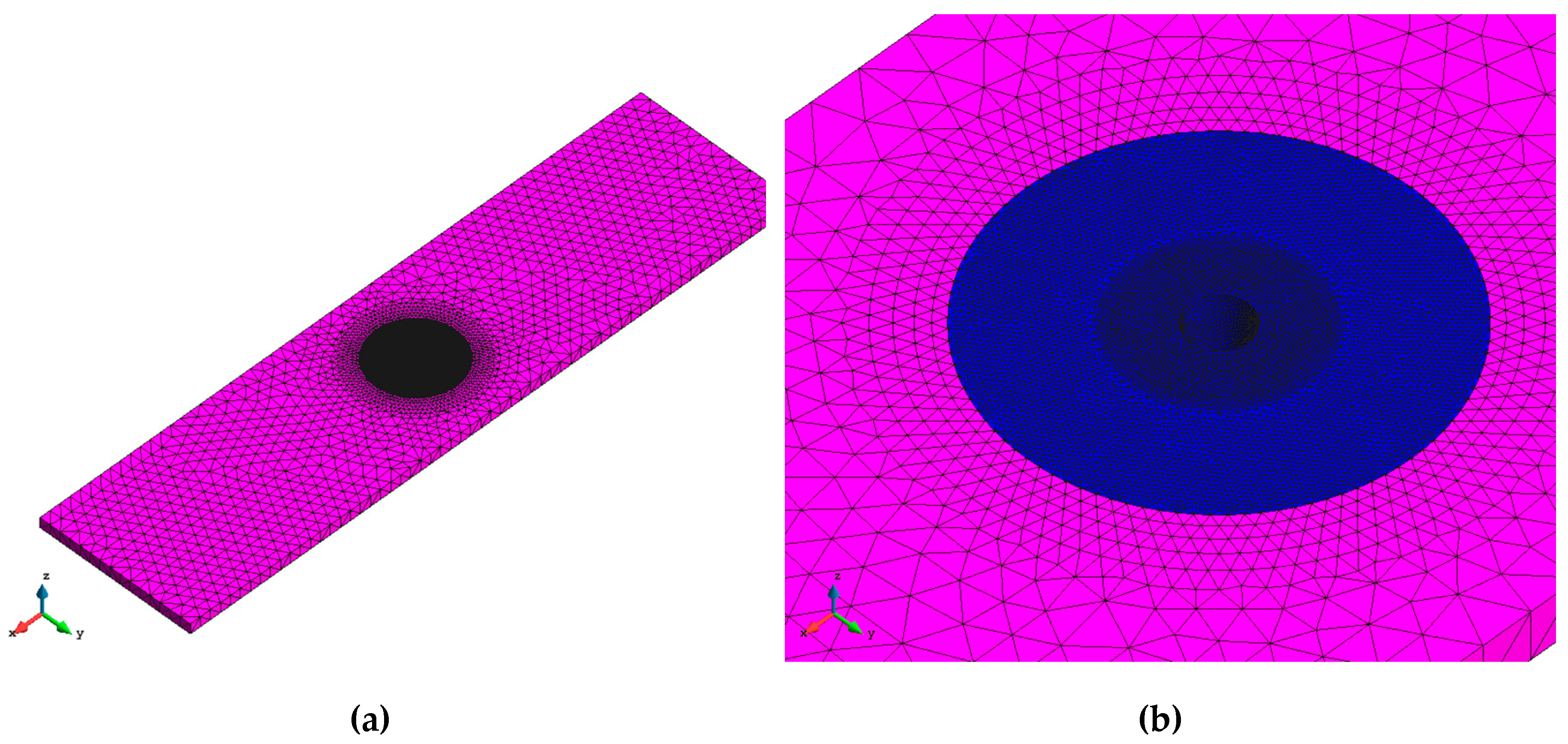
The computational model consists of 380,000 tetrahedral elements and 60,000 points approximately. Figure 9 shows the corresponding mesh used to discretize the model.
Heat generated through both plastic dissipation and frictional contact is considered.
The visco-plastic dissipation () is defined as
where is the Taylor–Quinney coefficient, is the deviatoric stress and is the strain rate.
The analysis considers the minimum and maximum friction tractions as τmin = 1.55 × 10⁷ and τmax = 3.1 × 10⁸ at tool/wor-kpiece contact surface, respectively. They are obtained from the calibration from the temperature field [30]. The in plane rotating angle β = 25° is calibrated from the temperature field obtained experimentally for the tilt angle 2.5° and presented in reference [21]. The qualitative mechanical results including the material flow are presented and compared for the cases (α = 0°, β = 0°) and (α = 2.5°, β = 25°).
To verify the choice of the rotating angle β = 25°, the longitudinal and the transversal forces are evaluated in both cases, without and with tilt angle. In the first case (without tilt angle), the forces are Fx = 170 N and Fy = 28000 N. Thus according to Equation (3), the in plane rotation angle is β ≅ 0°. In the second case (with tilt angle), the forces are Fx = 12000 N and Fy = 25000 N. Thus the in plane rotation angle is effectively β = 25°.
4.1. Thermal Effects
The thermal effects caused by the tool tilt angle are presented in this section in terms of the temperature field at the steady state.
Temperature
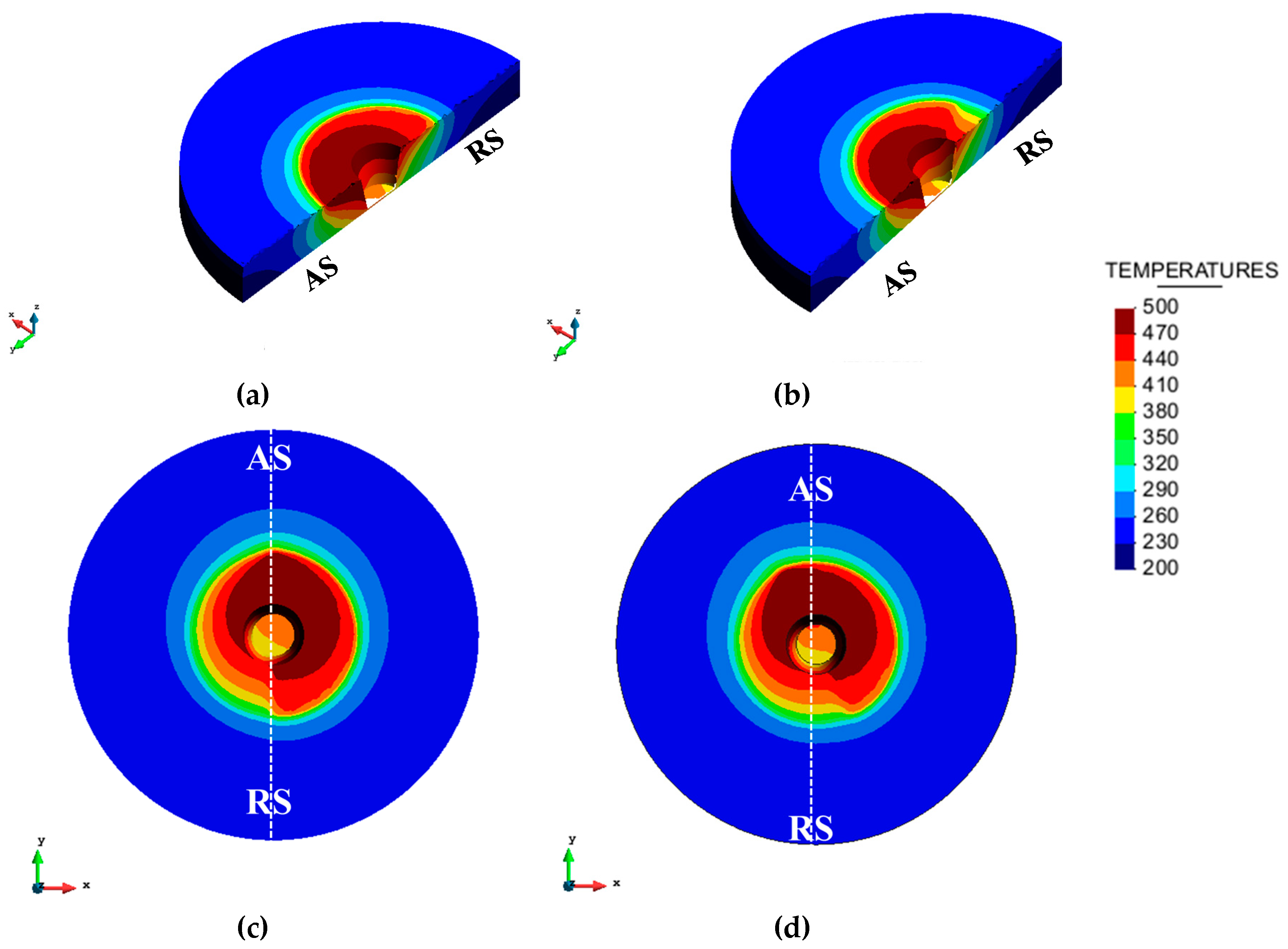
Figure 10 shows the computed temperature field for the tilt angles of 0° and 2.5°. The results are also shown on a vertical section at the center of the tool and the leading side in order to see the temperature field on the top surface and within the depth of the work piece.
The difference caused by the tool tilt angle on the temperature distribution can be clearly seen. In both cases, the maximum temperature is on the advancing side (AS) due to the non-uniform distribution of the friction at the contact surface between tool and work piece. The tool tilt angle causes a slight rotation of the temperature field. It increases the temperature in the neighboring zone of the FSW tool in the rear advancing side. This observation is in accordance with the experimental finding in [32].
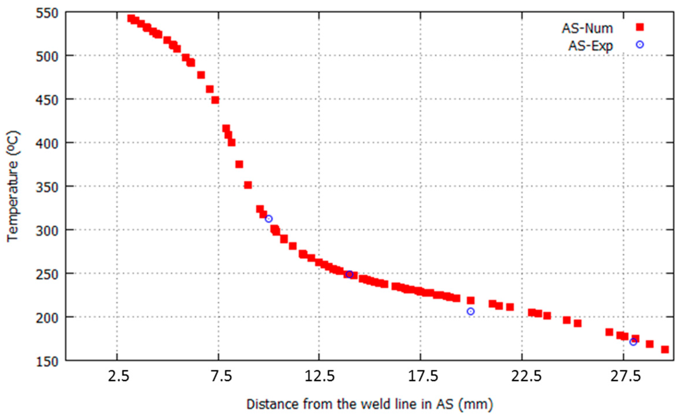
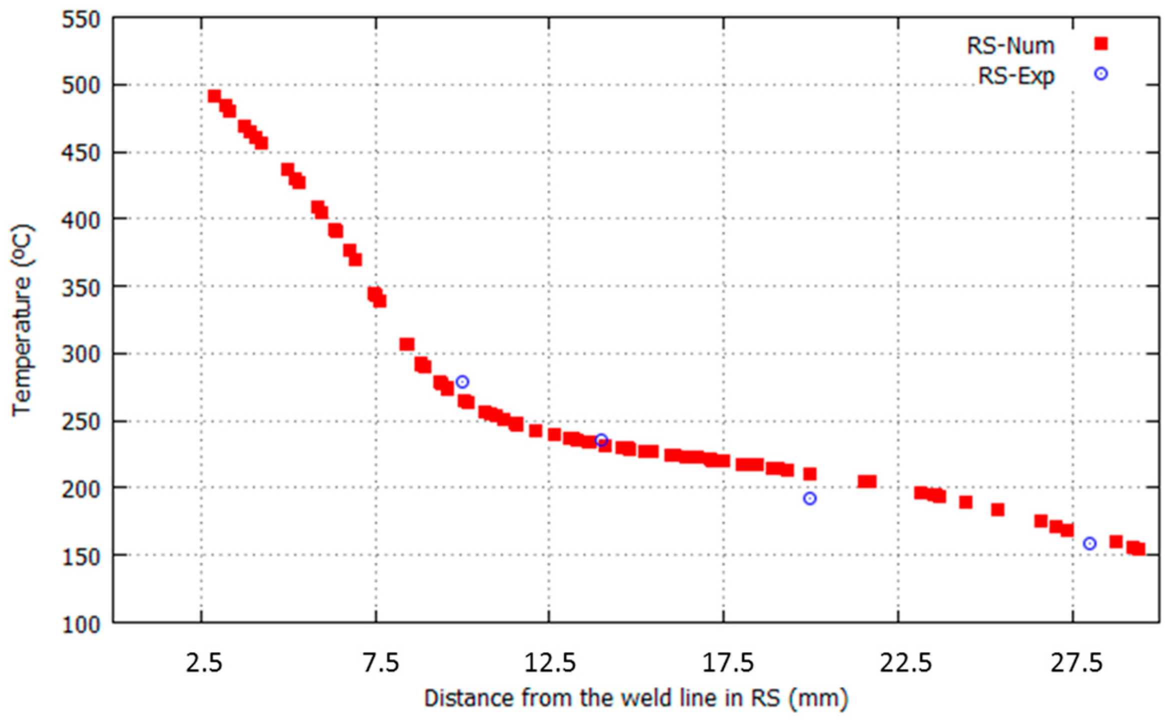
The difference of the temperature in the advancing (AS) and the retreating sides (RS) diminishes with the distance from the tool center. The computed maximum temperatures are compared with the measured ones presented in [21] for tilt angle 2.5° at different distances from the welding line on both advancing and retreating side, see Figure 11 and Figure 12.
It can be seen from the figures that a good agreement is achieved between numerical and experimental results at both retreating and advancing sides of the FSWelded work piece.
Table 1 compares the differences between the temperatures at retreating and advancing sides obtained from experimental and numerical analyses when a tilt angle of 2.5° is used. This comparison is performed for distances of 10, 14, 20 and 28 mm from the weld line. The agreement between numerical results and experimental data is remarkable.
4.2. Mechanical Effects
The mechanical effects caused by the tool tilt angle are presented in this section in terms of velocity, stresses and strain rate fields and material flow around the tool.
4.2.1. Velocity, Stress and Strain Rate
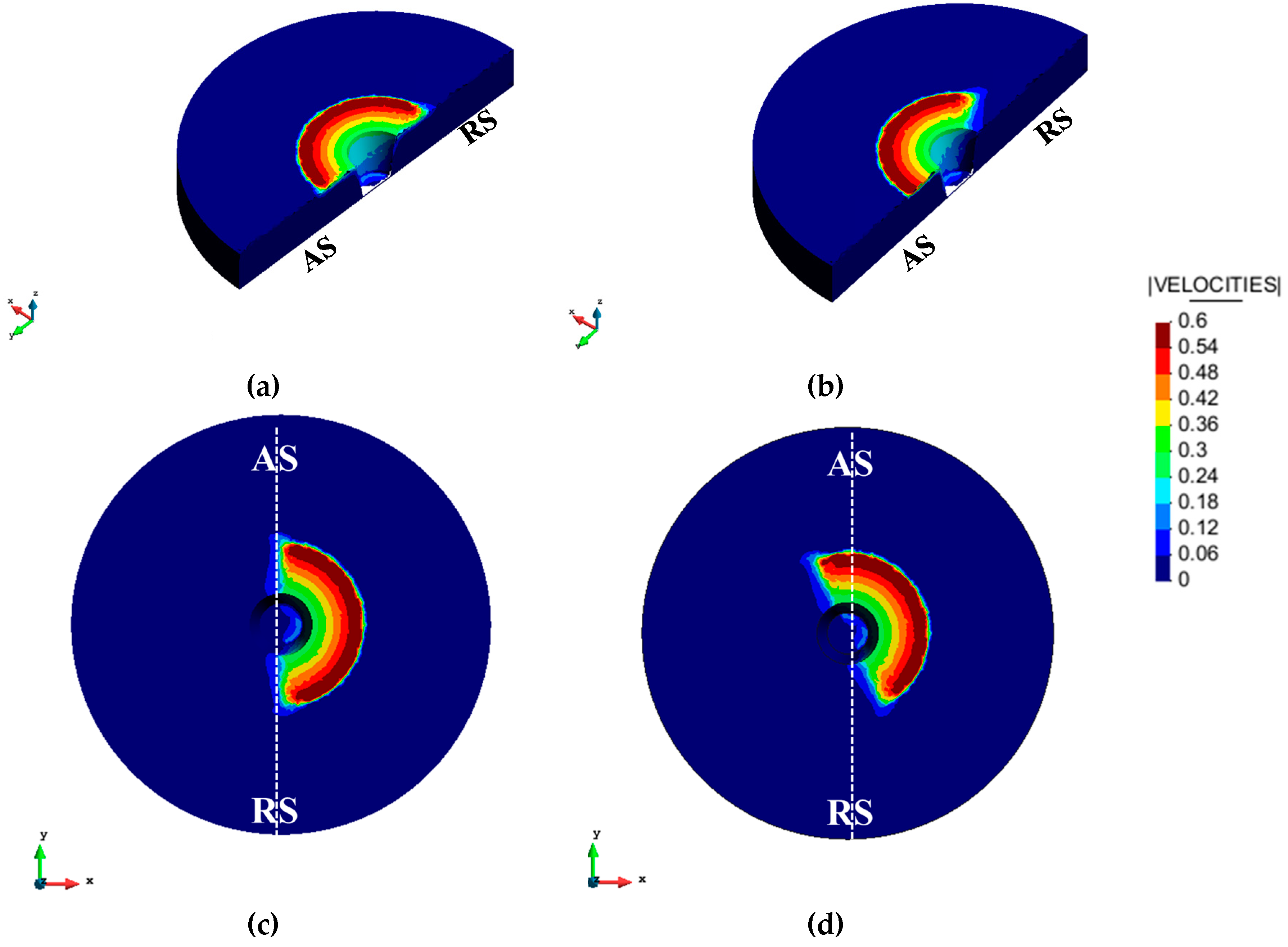
The computed velocity fields for α = 0° and α = 2.5° under the shoulder are depicted in Figure 13.
The velocity field in case of tilt angle α = 2.5° is rotated β = 25° (obtained from the calibration of the rotating angle β from the temperature field presented in [21]). As expected, the maximum velocity is at the border of the shoulder and in case of 0° tilt angle at the leading edge.
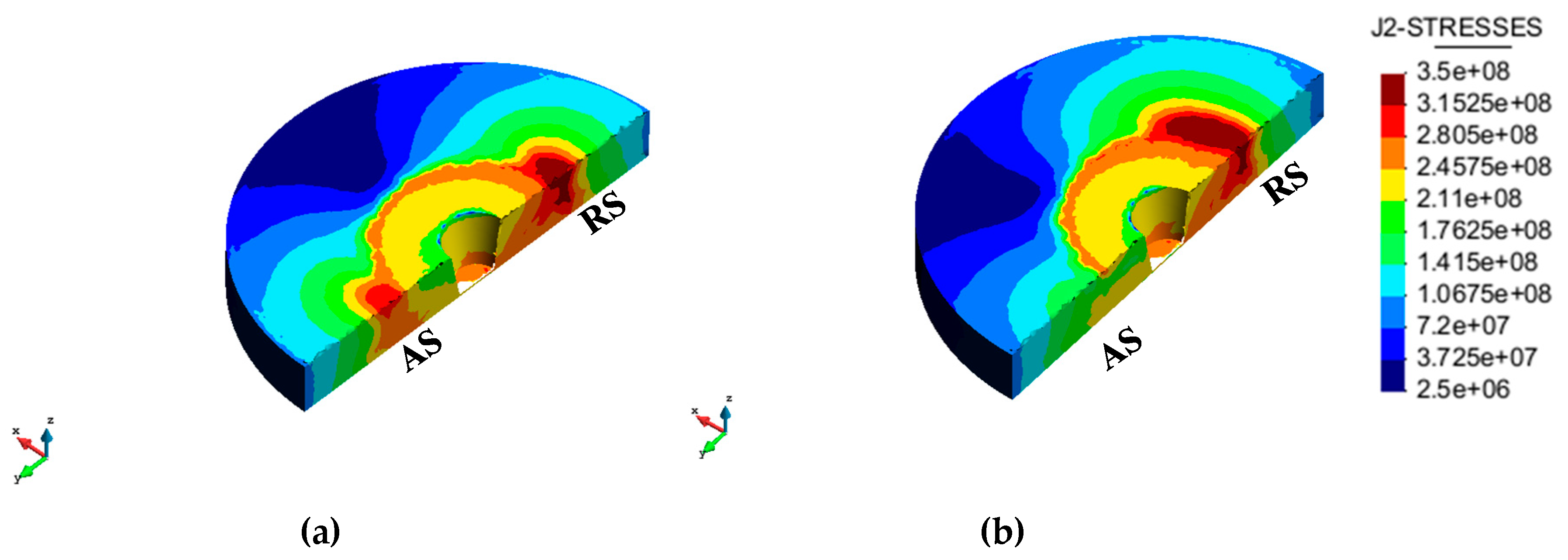
The J2 stress distributions under the shoulder in both studied cases are presented in Figure 14. The effect of the tilt angle is the rotation of this distribution and the increase of the stresses in the retreating side of the leading front. As the tool tilt angle increases the temperature on the rear advancing side of the tool (Figure 10), the material flow stress decreases correspondingly in this region and consequent softening of the material facilitates the flow. The computed behavior agrees with the finding in [32].
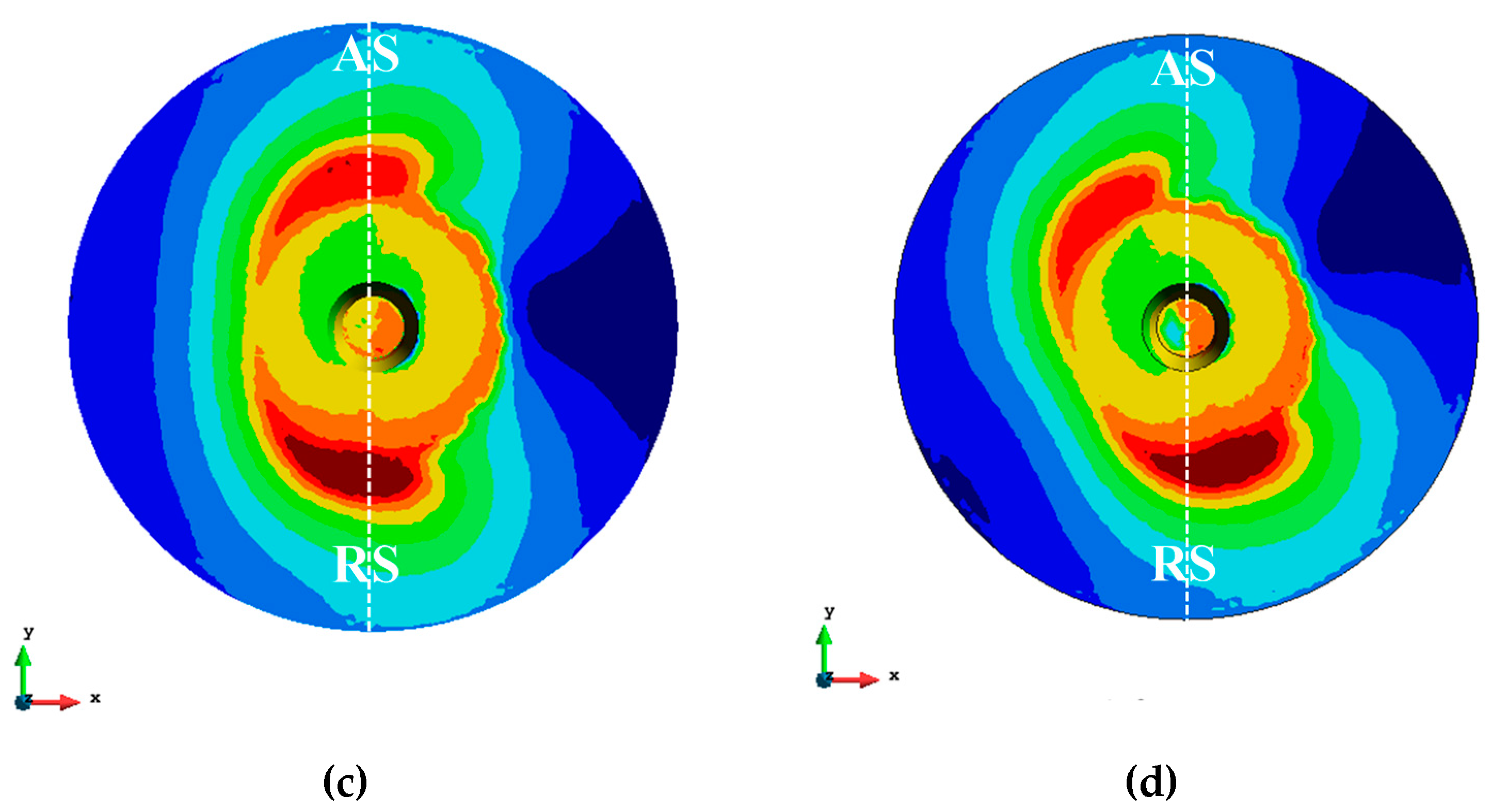
The strain rate distribution is shown in Figure 15 for both tilt angles. As the strain rate defines the stirring action in FSW [33], the distribution of the strain rate under the tool can give an insight to the material stirring. In case of having tilt angle, the stirring effect increases on the rear edge of the tool on the advancing side. Therefore the tilt angle can strengthen the material stirring action at this zone.
4.2.2. Material Flow
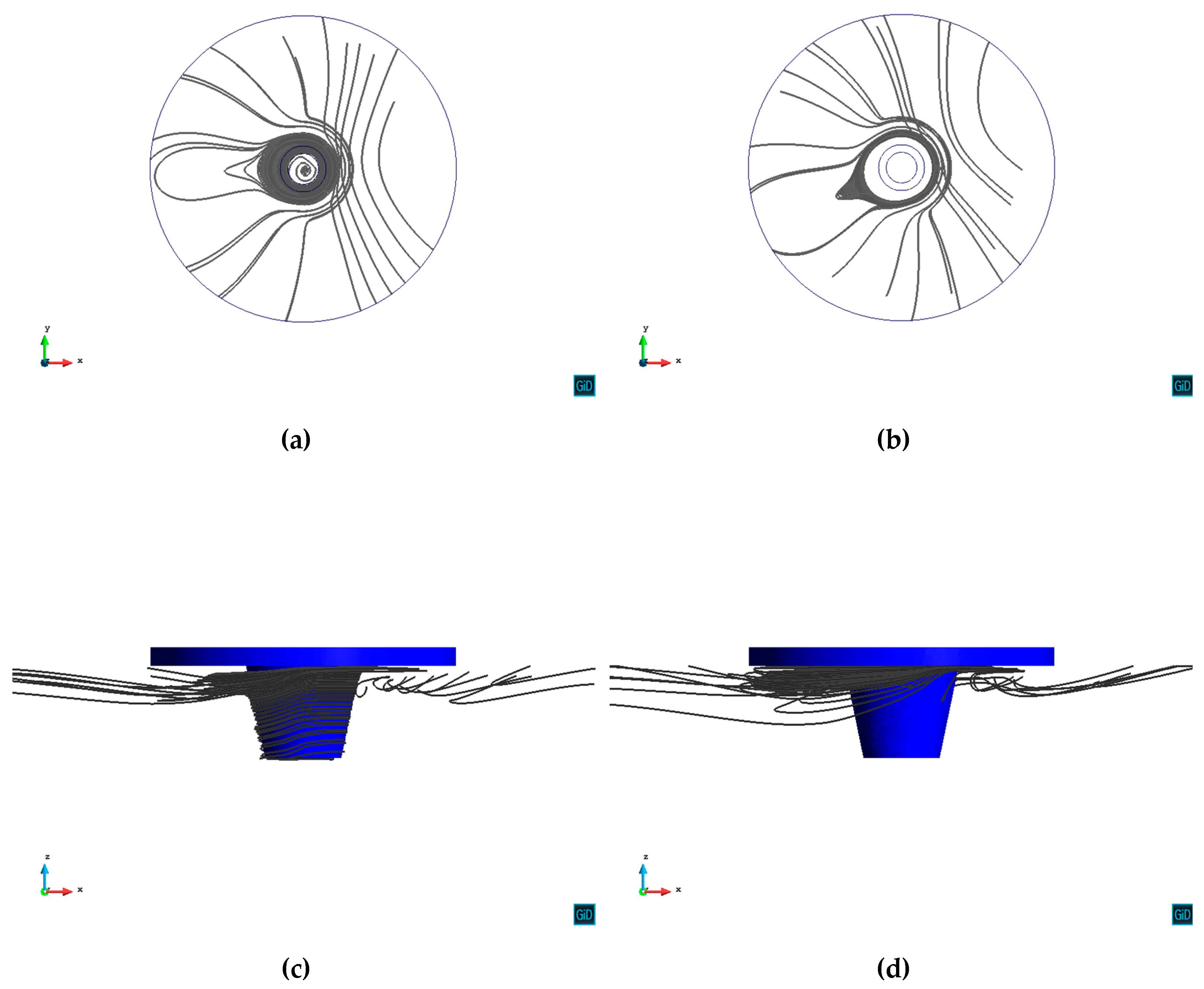
In order to visualize the differences on the material flow around the tool, stream lines are shown in Figure 16 and Figure 17 for both tilting cases at different depths (1 mm and 3 mm). In the xy plane, the effect of tilting manifests in the rotation of the streamlines (Figure 16b and Figure 17b).
In the case of no tilt angle and 1 mm depth, the material moves extensively around the tool. It is visible both in the xy plane (Figure 16a) and the xz plane showing that the material passes through all the depth of the tool (Figure 16c).
The material movement at the depth of 1 mm is very much affected by the shoulder movement (Figure 16c,d). Due to the tilt angle effect, material is trapped by the shoulder on the trailing edge (Figure 16d). It can be seen from Figure 16d that tilting induces a considerable accelerating effect behind the pin tool which is difficult to achieve in case of having no tilt angle. The reason for this is that a higher friction force exists on the rear side of the tool at the interface between the tool and the work piece. This stimulating effect of the tool tilt on the material flow helps to avoid the formation of defects in the weld, as low material velocity might lead to defect formation [34].
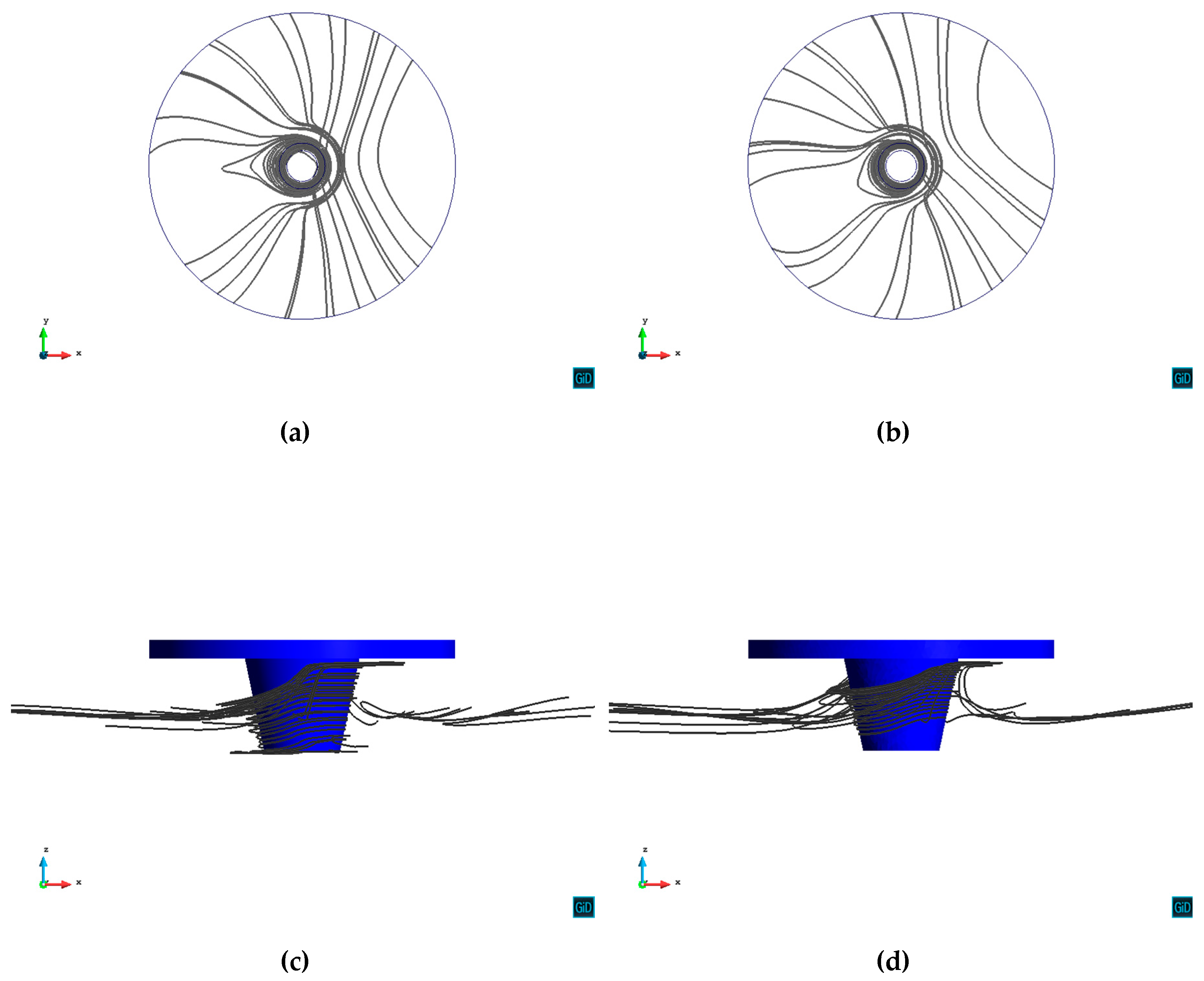
Further from the shoulder, at the depth of 3mm, the effect of tilting is less evident. In both cases of 0° and 2.5° tilt angles, apart from the rotation of the streamlines, the material movement around the tool is similar (Figure 17a,b). Without tilt angle, the material around the tool goes through all the depth of the pin resembling the case with tilt angle (Figure 17c,d).
It can be seen from Figure 17d that the material flows around the pin and then accumulates behind the tool on the weld.
Due to the higher temperature, softer material and greater frictional force in the trailing side of the tool, the material flow in the rear side of the FSW tool with the title angle is considerably enhanced, which assists to prevent the generation of defect.
5. Summary and Conclusions
In this work, the effect of tool tilt angle on the thermo-mechanical results (heat generation and material flow) in FSW process is studied. The thermo-mechanical results are presented for two tilt angle cases of α = 0° and α = 2.5°.
The friction model is modified by introducing an in plane rotating angle β of the friction shear stress in order to account for the effect of tilting. This rotation angle is calibrated from the temperature field obtained experimentally for the tilt angle 2.5°. The qualitative mechanical results including the material flow are presented and compared for the cases (α = 0°, β= 0°) and (α = 2.5°, β = 25°). It is verified that the rotating angle β can be defined through the relationship between the longitudinal and the transversal forces exerted on the tool.
It is observed that a non-zero tilt angle results in the rotation of the friction distribution under the shoulder. The computed temperature is compared with the experimental data and good agreement is obtained at both advancing and retreating sides. Differences between the temperatures at retreating and advancing sides are also compared with the experimental measurements.
It is observed that the tool tilt angle:
- increases stresses at the leading edge of the tool on the work piece.
- increases the temperature in the neighboring zone of the FSW tool in the rear advancing side.
- decreases the material flow stress in the rear advancing side.
- strengthens the material stirring action at trailing edge on the advancing side.
- facilitates the material flow behind the tool.
To sum up, the effect of the tool tilt angle can be represented by the in plane rotation of the corresponding thermo mechanical fields. Owing to this, the material flow behind the FSW tool is considerably improved contributing to the prevention of the defect formation. Future work will be addressed to extend the experimental evidence in order to correlate the tilt angle and process parameters with obtained in plane rotation of the friction shear traction.
Author Contributions
N.D., M.C. (Miguel Cervera) and M.C. (Michele Chiumenti) developed the numerical model; N.D. implemented the model; N.D. and M.C. (Miguel Cervera) discussed and analyzed the data.
Funding
This research received no external funding.
Conflicts of Interest
The authors declare no conflict of interest.
References
- Langari, J.; Kolahan, F.; Aliakbari, K. Effect of tool speed on axial force, mechanical properties and weld morphology of friction stir welded joints of a7075-t651. Int. J. Eng. 2016, 29, 403–410. [Google Scholar]
- Mehta, K.P.; Badheka, V.J. Effects of tilt angle on properties of dissimilar friction stir welding copper to aluminum. Mater. Manuf. Process. 2016, 31, 255–263. [Google Scholar] [CrossRef]
- Jaiganesh, V.; Maruthu, B.; Gopinath, E. Optimization of process parameters on friction stir welding of high density polypropylene plate. Procedia Eng. 2014, 97, 1957–1965. [Google Scholar] [CrossRef]
- Dialami, N.; Chiumenti, M.; Cervera, M.; Agelet de Saracibar, C.; Ponthot, J.-P. Numerical simulation and visualization of material flow in friction stir welding via particle tracing. In Numerical Simulations of Coupled Problems in Engineering; Springer International Publishing: Cham, Switzerland, 2014; pp. 157–169. [Google Scholar]
- Dialami, N.; Chiumenti, M.; Cervera, M.; de Saracibar, C.A. A fast and accurate two-stage strategy to evaluate the effect of the pin tool profile on metal flow, torque and forces during friction stir welding. Int. J. Mech. Sci. 2017, 122, 215–227. [Google Scholar] [CrossRef]
- Chien, C.H.; Lin, W.B.; Chen, T. Optimal FSW process parameters for aluminum alloys AA5083. J. Chin. Inst. Eng. 2011, 34, 99–105. [Google Scholar] [CrossRef] [Green Version]
- Arici, A.; Selale, S. Effects of tool tilt angle on tensile strength and fracture locations of friction stir welding of polyethylene. Sci. Technol. Weld. Join. 2007, 12, 536–539. [Google Scholar] [CrossRef]
- Payganeh, G.H.; Arab, N.B.M.; Asl, Y.D.; Ghasemi, F.A.; Boroujeni, M.S. Effects of friction stir welding rocess parameters on appearance and strength of polypropylene composite welds. Int. J. Phys. Sci. 2011, 6, 595–601. [Google Scholar]
- Shazly, M.; El-raey, M. Friction stir welding of polycarbonate sheets. In Characterization of Minerals, Metals, and Materials; Wiley: Hoboken, NJ, USA, 2014; pp. 555–563. [Google Scholar]
- Reshad Seighalani, K.; Besharati Givi, M.K.; Nasiri, A.M.; Bahemmat, P. Investigations on the Effects of the Tool Material, Geometry, and Tilt Angle on Friction Stir Welding of Pure Titanium. J. Mater. Eng. Perform. 2010, 19, 955. [Google Scholar] [CrossRef]
- Banik, A.; Roy, B.S.; Barma, J.D.; Saha, S.C. An experimental investigation of torque and force generation forvarying tool tilt angles and their effects on microstructure and mechanical properties: Friction stir welding of AA 6061-T6. J. Manuf. Process. 2018, 31, 395. [Google Scholar] [CrossRef]
- Elyasi, M.; Aghajani Derazkola, H.; Hosseinzadeh, M. Investigations of tool tilt angle on properties friction stir welding of A441 AISI to AA1100 aluminium. Proc. Inst. Mech. Eng. Part B J. Eng. Manuf. 2016, 230, 1234–1241. [Google Scholar] [CrossRef]
- Hamid, H.A.D.; Roslee, A.A. Study the Role of Friction Stir Welding Tilt Angle on Microstructure and Hardness. Appl. Mech. Mater. 2015, 799–800, 434–438. [Google Scholar] [CrossRef]
- Meshram, S.D.; Reddy, G.M. Influence of Tool Tilt Angle on Material Flow and Defect Generation in Friction Stir Welding of AA2219. Def. Sci. J. 2018, 68, 512–518. [Google Scholar]
- Long, L.; Chen, G.; Zhang, S.; Liu, T.; Shi, Q. Finite-element analysis of the tool tilt angle effect on the formation of friction stir welds. J. Manuf. Process. 2017, 30, 562–569. [Google Scholar] [CrossRef]
- Chauhan, P.; Jain, R.; Pal, S.K.; Singh, S.B. Modeling of defects in friction stir welding using coupled Eulerian and Lagrangian method. J. Manuf. Process. 2018, 34, 158–166. [Google Scholar] [CrossRef]
- Aghajani Derazkola, H.; Simchi, A. Experimental and thermomechanical analysis of friction stir welding of poly(methyl methacrylate) sheets. Sci. Technol. Weld. Join. 2018, 23, 209–218. [Google Scholar] [CrossRef]
- Hamilton, C.; Dymek, S.; Kopyscianski, M.; Weglowska, A.; Pietras, A. Numerically Based Phase Transformation Maps for Dissimilar Aluminum Alloys Joined by Friction Stir-Welding. Metals 2018, 8, 324. [Google Scholar] [CrossRef]
- Casalino, G.; Facchini, F.; Mortello, M.; Mummolo, G. ANN modelling to optimize manufacturing processes: The case of laser welding, IFAC Proceedings. IFAC-PapersOnline 2016, 49, 378–383. [Google Scholar] [CrossRef]
- Pathak, M.; Jaiswal, D. Application of Artificial Neural Network in Friction Stir Welding: A Review. Int. J. Technol. Explor. Learn. 2014, 3, 513–517. [Google Scholar]
- Zhang, S.; Shi, Q.; Liu, Q.; Xie, R.; Zhang, G.; Chen, G. Effects of tool tilt angle on the in-process heat transfer and mass transfer during friction stir welding. Int. J. Heat Mass Transf. 2018, 125, 32–42. [Google Scholar] [CrossRef]
- Guerdoux, S. Numerical Simulation of the Friction Stir Welding Process. Ph.D. Thesis, École Nationale Supérieure des Mines de Paris, Paris, France, 2007. [Google Scholar]
- Dialami, N.; Chiumenti, M.; Cervera, M.; de Saracibar, C.A. An apropos kinematic framework for the numerical modeling of friction stir welding. Comput. Struct. 2013, 117, 48–57. [Google Scholar] [CrossRef]
- Cervera, M.; Agelet de Saracibar, C.; Chiumenti, M. COMET: Coupled Mechanical and Thermal Analysis, Data Input Manual, Version 5.0, Technical Report IT-308. 2002. Available online: http://www.cimne.upc.es (accessed on June 2002).
- Dialami, N.; Cervera, M.; Chiumenti, M.; Agelet de Saracibar, C. Local-global strategy for the prediction of residual stresses in FSW processes. Int. J. Adv. Manuf. Technol. 2016, 88, 3099–3111. [Google Scholar] [CrossRef]
- Veljic, D.M.; Rakin, M.P.; Perovic, M.M. Heat generation during plunge stage in friction stir welding. Therm. Sci. 2013, 17, 489–496. [Google Scholar] [CrossRef] [Green Version]
- Zhang, Z.; Zhang, H.W. Effect of contact model on numerical simulation of friction stir welding. Acta Metall. Sin. 2008, 44, 85–90. [Google Scholar]
- Chao, Y.J.; Qi, X.; Tang, W. Heat transfer in friction stir welding: Experimental and numerical studies. J. Manuf. Sci. Eng. 2003, 125, 138–145. [Google Scholar] [CrossRef]
- Schmidt, H.; Hattel, J. A local model for the thermomechanical conditions in friction stir welding. Model. Simul. Mater. Sci. Eng. 2005, 13, 77–93. [Google Scholar] [CrossRef]
- Dialami, N.; Chiumenti, M.; Cervera, M.; Segatori, A.; Osikowicz, W. Enhanced friction model for Friction Stir Welding (FSW) analysis: Simulation and experimental validation. Int. J. Mech. Sci. 2017, 133, 555–567. [Google Scholar] [CrossRef]
- Jung, J.; Oak, J.-J.; Kim, Y.-H.; Cho, Y.J.; Park, Y.H. Wear Behaviors of Pure Aluminum and Extruded Aluminum Alloy (AA2024-T4) Under Variable Vertical Loads and Linear Speeds. Met. Mater. Int. 2017, 23, 1097–1105. [Google Scholar] [CrossRef]
- Sheppard, T.; Wright, D.S. Determination of flow-stress constitutive equation for aluminum-alloys at elevated-temperatures. Met. Technol. 1979, 6, 215–223. [Google Scholar] [CrossRef]
- Pashazadeh, H.; Teimournezhad, J.; Masoumi, A. Numerical investigation on the mechanical, thermal, metallurgical and material flow characteristics in friction stir welding of copper sheets with experimental verification. Mater. Des. 2016, 55, 619–632. [Google Scholar] [CrossRef]
- Zhu, Y.; Chen, G.; Chen, Q.; Zhang, G.; Shi, Q. Simulation of material plastic flow driven by non-uniform friction force during friction stir welding and related defect prediction. Mater. Des. 2016, 108, 400–410. [Google Scholar] [CrossRef]
Figure 1.
Cross-sectional view of an (exaggeratedly) tilted tool inside the work piece.

Figure 2.
Two-stage strategy concept.

Figure 3.
Friction shear traction distribution under the tool (0° tilt angle).

Figure 4.
Schematic contact print observed in the experiment of FSW. Without tilt angle (top); with tilt angle (bottom).
Figure 4.
Schematic contact print observed in the experiment of FSW. Without tilt angle (top); with tilt angle (bottom).

Figure 5.
Contact condition under the (counterclockwise) rotating tool. Without tilt angle (left); with tilt angle (right).
Figure 5.
Contact condition under the (counterclockwise) rotating tool. Without tilt angle (left); with tilt angle (right).

Figure 6.
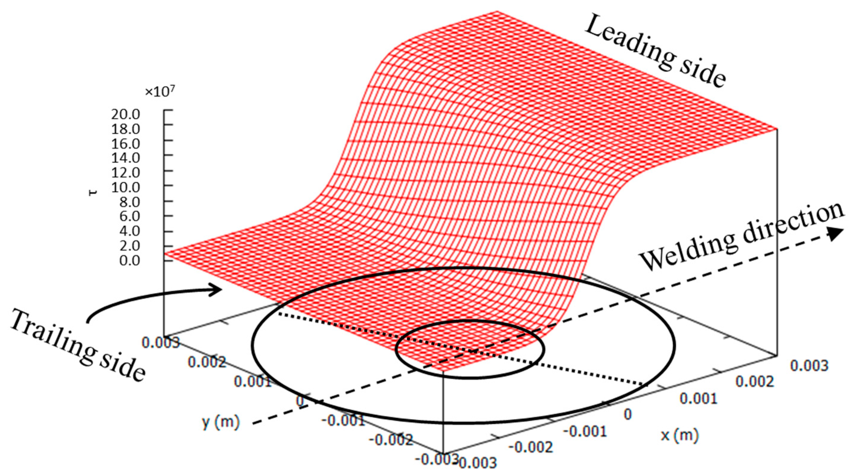
Friction shear traction distribution under the tool (2.5° tilt angle).

Figure 7.
The geometry model.

Figure 8.
Conical tool geometry.

Figure 9.
Mesh resolution. (a) entire domain; (b) zoom on the stir zone.

Figure 10.
Temperature distribution. (a,c) 0° tilt angle; (b,d) 2.5° tilt angle.

Figure 11.
Temperature comparison between numerical results and experimental data on the advancing side (AS) at different distances from the weld line (2.5° tilt angle).
Figure 11.
Temperature comparison between numerical results and experimental data on the advancing side (AS) at different distances from the weld line (2.5° tilt angle).

Figure 12.
Temperature comparison between numerical results and experimental data on the retreating side (RS) at different distances from the weld line (2.5° tilt angle).
Figure 12.
Temperature comparison between numerical results and experimental data on the retreating side (RS) at different distances from the weld line (2.5° tilt angle).

Figure 13.
Velocity field. (a,c) 0° tilt angle (b,d) 2.5° tilt angle.

Figure 14.
J2 stress field. (a,c) 0° tilt angle; (b,d) 2.5° tilt angle.


Figure 15.
J2 strain rate field. (a,c) 0° tilt angle; (b,d) 2.5° tilt angle.

Figure 16.
Material flow paths in horizontal and vertical view at depth of 1 mm. (a) 0° tilt angle, depth of 1 mm, xy plane; (b) 2.5° tilt angle, depth of 1 mm, xy plane; (c) 0° tilt angle, depth of 1 mm, xz plane; (d) 2.5° tilt angle, depth of 1 mm, xz plane.
Figure 16.
Material flow paths in horizontal and vertical view at depth of 1 mm. (a) 0° tilt angle, depth of 1 mm, xy plane; (b) 2.5° tilt angle, depth of 1 mm, xy plane; (c) 0° tilt angle, depth of 1 mm, xz plane; (d) 2.5° tilt angle, depth of 1 mm, xz plane.

Figure 17.
Material flow paths in horizontal and vertical view at depth of 3 mm. (a) 0° tilt angle, depth of 3 mm, xy plane; (b) 2.5° tilt angle, depth of 3 mm, xy plane; (c) 0° tilt angle, depth of 3 mm, xz plane; (d) 2.5° tilt angle, depth of 3 mm, xz plane.
Figure 17.
Material flow paths in horizontal and vertical view at depth of 3 mm. (a) 0° tilt angle, depth of 3 mm, xy plane; (b) 2.5° tilt angle, depth of 3 mm, xy plane; (c) 0° tilt angle, depth of 3 mm, xz plane; (d) 2.5° tilt angle, depth of 3 mm, xz plane.


Table 1.
Difference between temperatures on the advancing and retreating sides at different locations from the weld line.
Table 1.
Difference between temperatures on the advancing and retreating sides at different locations from the weld line.
| Distance from the Welding Line (mm) | Temperature Difference of AS and RS (Tilt Angle of 2.5°) | |
|---|---|---|
| Experimental Data | Numerical Analysis | |
| 10 | 35 | 36 |
| 14 | 15 | 15 |
| 20 | 13 | 11 |
| 28 | 11 | 10 |
© 2018 by the authors. Licensee MDPI, Basel, Switzerland. This article is an open access article distributed under the terms and conditions of the Creative Commons Attribution (CC BY) license (http://creativecommons.org/licenses/by/4.0/).
Share and Cite
MDPI and ACS Style
Dialami, N.; Cervera, M.; Chiumenti, M. Effect of the Tool Tilt Angle on the Heat Generation and the Material Flow in Friction Stir Welding. Metals 2019, 9, 28. https://0-doi-org.brum.beds.ac.uk/10.3390/met9010028
AMA Style
Dialami N, Cervera M, Chiumenti M. Effect of the Tool Tilt Angle on the Heat Generation and the Material Flow in Friction Stir Welding. Metals. 2019; 9(1):28. https://0-doi-org.brum.beds.ac.uk/10.3390/met9010028
Chicago/Turabian StyleDialami, Narges, Miguel Cervera, and Michele Chiumenti. 2019. "Effect of the Tool Tilt Angle on the Heat Generation and the Material Flow in Friction Stir Welding" Metals 9, no. 1: 28. https://0-doi-org.brum.beds.ac.uk/10.3390/met9010028
Note that from the first issue of 2016, this journal uses article numbers instead of page numbers. See further details here.