Article

Directed Irradiation Synthesis as an Advanced Plasma Technology for Surface Modification to Activate Porous and “as-received” Titanium Surfaces

1
Department of Nuclear, Plasma and Radiological Engineering, Grainger College of Engineering, University of Illinois at Urbana-Champaign, 216 Talbot Laboratory, 104 South Wright Street, Urbana, IL 61801, USA
2
Micro and Nanotechnology Laboratory, University of Illinois at Urbana-Champaign, 208 N Wright St, Urbana, IL 61801, USA
3
Department of Bioengineering, College of Engineering, University of Illinois at Urbana-Champaign, 1406 W. Green Street, Urbana, IL 61801, USA
4
Group of Advanced Biomaterials and Regenerative Medicine, Bioengineering Program, University of Antioquia, Cl. 67 ##53-108, Medellín 050010, Antioquia, Colombia
5
Los Alamos National Laboratory, New Mexico, NM 87545, USA
6
School of Materials Engineering, Purdue University, West Lafayette, IN 47907, USA
7
Departamento de Ingeniería y Ciencia de los Materiales y del Transporte, Escuela Politécnica Superior, Universidad de Sevilla, Virgen de África 7, 41011 Sevilla, Spain
8
City of Hope National Research Medical Center, 1500 E Duarte Rd, Duarte, CA 91010, USA
*
Authors to whom correspondence should be addressed.
Submission received: 15 November 2019 / Revised: 10 December 2019 / Accepted: 12 December 2019 / Published: 15 December 2019
(This article belongs to the Special Issue Tailor-Made Porous Biomaterials for Hard and Soft Tissues)

Abstract

:
For the design of smart titanium implants, it is essential to balance the surface properties without any detrimental effect on the bulk properties of the material. Therefore, in this study, an irradiation-driven surface modification called directed irradiation synthesis (DIS) has been developed to nanopattern porous and “as-received” c.p. Ti surfaces with the aim of improving cellular viability. Nanofeatures were developed using singly-charged argon ions at 0.5 and 1.0 keV energies, incident angles from 0° to 75° degrees, and fluences up to 5.0 × 1017 cm−2. Irradiated surfaces were evaluated by scanning electron microscopy, atomic force microscopy and contact angle, observing an increased hydrophilicity (a contact angle reduction of 73.4% and 49.3%) and a higher roughness on both surfaces except for higher incident angles, which showed the smoothest surface. In-vitro studies demonstrated the biocompatibility of directed irradiation synthesis (DIS) reaching 84% and 87% cell viability levels at 1 and 7 days respectively, and a lower percentage of damaged DNA in tail compared to the control c.p. Ti. All these results confirm the potential of the DIS technique to modify complex surfaces at the nanoscale level promoting their biological performance.

Graphical Abstract

1. Introduction

As the size of the elderly population grows, many people undergo procedures requiring medical implant devices which involve significant risks related to implant rejection, inflammation, and bacterial infection. In particular, implant failure and its inability to integrate properly with bone tissue have become a public health issue, as the World Health Organization recognized [1,2]. Nearly one million people suffer from infections each year in the United States alone due to medical implants [3]. Additionally, permanent implants have the potential to develop complications years after placement due to poor tissue integration, requiring follow-up surgery for replacement [4,5]. Therefore, one of the most critical challenges to improve implant performance is to design a biomimetic scaffold which reproduces the native bone tissue features [6]. In this sense, the chemical and physical properties of the surface of medical devices play a key role in the integration of the implant. Medical-grade titanium (Ti) alloys and commercially pure Ti (c.p. Ti) have shown the best biomaterials for bone replacement due to its excellent balance between biomechanical properties and in-vivo biocompatibility. However, the elastic mismatch between c.p. Ti implant material and the host bone tissue, also well-known as “stress shielding”, results in bone resorption around the implants. In addition, c.p. Ti and Ti-based materials offer a bio-inert surface that promotes poor cell interactions at the biointerface. In these scenarios, c.p. Ti devices induce a foreign body reaction which prevents the proper osseointegration process. This natural reaction can be modulated by designing biomimetic surfaces that enhance biocompatibility and bioactivity (i.e., inducing a favorable biological response and favoring bone osseointegration) [6].
To address the stress shielding issue, several studies have pointed out the development of porous scaffolds that mimic the bulk mechanical properties of bone. There are a variety of manufacturing processes to obtain a suitable porosity including electron beam melting process [7], creep expansion of argon-filled pores [8], directional aqueous freeze casting [9], rapid prototyping techniques [10], laser-engineered net shaping [11], electric current assisted sintering techniques [12,13], conventional and non-conventional powder metallurgy [14,15] and space-holder techniques [16,17]. Among those techniques, powder metallurgy (PM) provides a high-fidelity control of compacting pressure, sintering temperature and processing time parameters which are required for a porosity architecture that closely reproduce the native trabecular bone tissue and ultimately reducing stress shielding effect. Our group has optimized the PM conditions using loose sintering process (LS), a non-conventional PM alternative to ensure the desired balance between low stiffness (reduced stress-shielding) and high mechanical strength (fatigue resistance) [15]. In the loose-sintering process, compaction pressure is not necessary and has emerged as an attractive route to produce porous Ti implants with high porosity, to achieve similar mechanical properties of cancellous bone (Young’s moduli between 0.5 to 1 GPa) [15].
On the other hand, to reduce the inert character of Ti-based materials, a variety of techniques enable the control of surface topography and chemistry properties to promote the desired surface bioactivation. Recently, ground-breaking work is also elucidating the ability for surface micron and sub-micron scale patterns to act as biophysical stimuli guiding cell morphology, proliferation, differentiation and signaling cascades in mechano-transduction events that can aid local regeneration of bone tissue [18,19]. Concerning the topographical changes, a wide variety of techniques modify the so-called “surface roughness” to improve osseointegration. Most of these techniques, including chemical etching, sand-blasting, and laser ablation, among others, focus on a variation of what we define as “kinetic roughening” or the random variation of surface peak heights and depths that on average results in an increase in roughness values that can vary on average from 0.5–5 µm. Indeed, several studies have reported an enhancement of cell adhesion and differentiation of mesenchymal stem cells growing on semi order nanopattern surfaces compared to flat or totally ordered or even totally random nanofeatures distribution [20,21,22,23]. In addition, Abagnale and coworkers observed that nanopattern surfaces based on ridges of 2 µm induced a preferential osteogenic differentiation (osteocalcin and osteopontin protein expression) over the adipogenic compromise of mesenchymal stem cells [24]. Similarly, the height of the nanostructures also affects cell behavior, observing a promotion of bone markers expression and larger focal adhesion on 15 nm height than 100 nm nanopattern surfaces [25]. Although, it should point it out that the improvement of cell adhesion just by roughening modification at microscale order has as a major consequence, the promotion of bacterial attachment and subsequent biofilm formation [26].
Therefore, inducing high-fidelity nanopatterning of biomaterial surfaces has emerged as one of the most important and effective modifications to provide both enhanced osseointegration and a controlled immuno-response while minimizing potential bacterial infection. In the development of nanopatterning surfaces through conventional techniques the main drawback relies on the physical limits of fabrication structures smaller than 50 nm. Therefore, bottom-up techniques that rely on self-assembly, self-organization, and local patterning, have become technologies capable of pattern biocompatible surface nanostructures. However, one of the biggest challenges to these types of bottom-up techniques is the inability to induce patterns on the intrinsic engineering materials that make up fabricated materials for biomedical devices such as orthopedic implants. Directed irradiation synthesis (DIS) introduces a synthesis process that is scalable to high-volume, high-value manufacturing by its intrinsic large-area simultaneous exposure of materials surfaces and interfaces. Broad-beam ions combined with rastered focused ions and gradient ion-beam profiles are sequenced and/or combined with reactive and/or non-reactive thermal beams that control the surface topography, chemistry, and structure at the micro and nano-scale level [27].
There are no studies published, as far as the authors know, where energetic ion-beams are used for nanoscale patterning and structuring of porous and non-porous Ti-based materials engineered to stimulate cell behavior. Several studies have reported the effects of nanopatterned polymeric surfaces with mesenchymal stem cells [28,29]. However, metallic substrates required the combination of different strategies (lithography and plasma treatments) to reproduce the designed patterned on top of the surface [25,30,31]. Many studies rely on nanoscale modification using masks such as conventional lithography methods rendering direct nanopatterning of clinically-relevant biomaterial intractable. Therefore, this work aims to examine the smart design of porous and non-porous c.p. Ti interfaces with high-fidelity nanopatterning harnessing DIS to influence cellular behavior. To that end, treated samples were characterized in detail, in order to establish relationships with DIS conditions, surface energy, and structural properties. These nanopattern surfaces were also biologically evaluated by using human aortic smooth muscle cells (HASMCs) for cytotoxicity assessment.

2. Materials and Methods

2.1. Manufacturing of Porous and Non-Porous c.p. Ti Samples

The powder of c.p. Ti (SE-JONG Materials Co. Ltd., Incheon, Korea) used for the blends was manufactured by a hydrogenation/dehydrogenation process. Several mixing times were evaluated. Powder was divided into three parts each time (surface, bulk and bottom of the recipient) and particle size distribution was measured, reaching homogeneity at ≥40 min. The particle size distribution corresponded to 10, 50 and 90% passing percentages of 9.7, 23.3 and 48.4 μm, respectively. The chemical composition of the Ti powder used was equivalent to c.p. Ti Grade IV according to the ASTM F67-00 standard [32]. This c.p. Ti powder had an apparent density (c.p. Ti powder accommodation without any pressure or vibration) of 1.30 ± 0.01 g/cm3 and a tap density (powder accommodation after providing certain vibration) of 1.77 ± 0.04 g/cm3 and the total porosity percentage associated to those values were of 39.2 ± 0.8% and 28.8 ± 0.1%, respectively. The blends of c.p. Ti powder were prepared using a Turbula® T2C blender for 40 min to ensure good homogenization. Two different porosities were evaluated to address the irradiation influence on porous c.p. Ti samples. Loose sintering technique (LS) which is performed without any compaction pressure, 0 MPa (PPS1) was compared to conventional PM via a low compaction pressure (PPS2). The compacting step of PPS2 was carried out using an Instron 5505 universal machine to apply the pressure used of 38.5 MPa, according to optimum results obtained by the authors in a published work [14]. The compacting loading rate was 6 kN/s, dwelling time was 2 min and unloading time was 15 s for decreasing load up to 150 N. The sintering process was performed in a Carbolyte® STF 15/75/450 ceramic furnace with a horizontal tube at 1000 °C and 1100 °C for 2 h using a high vacuum (~5 × 10⁻⁵ mbar). The diameter of compaction die (8 mm) and powder mass were selected to obtain samples in which the effect of compaction pressure was minimized [14]. Surface treatment of non-porous c.p. Ti samples was achieved by conventional machining of discs (diameter of 2 cm, thickness of 0.5 cm) that were provided by City of Hope of Cancer (Duarte, CA, USA).

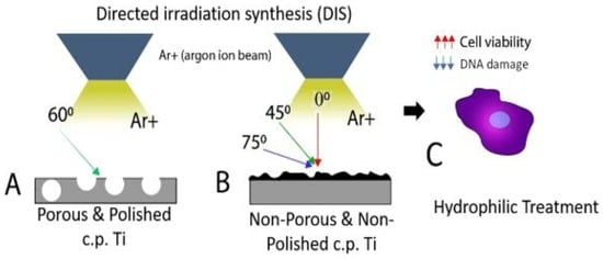
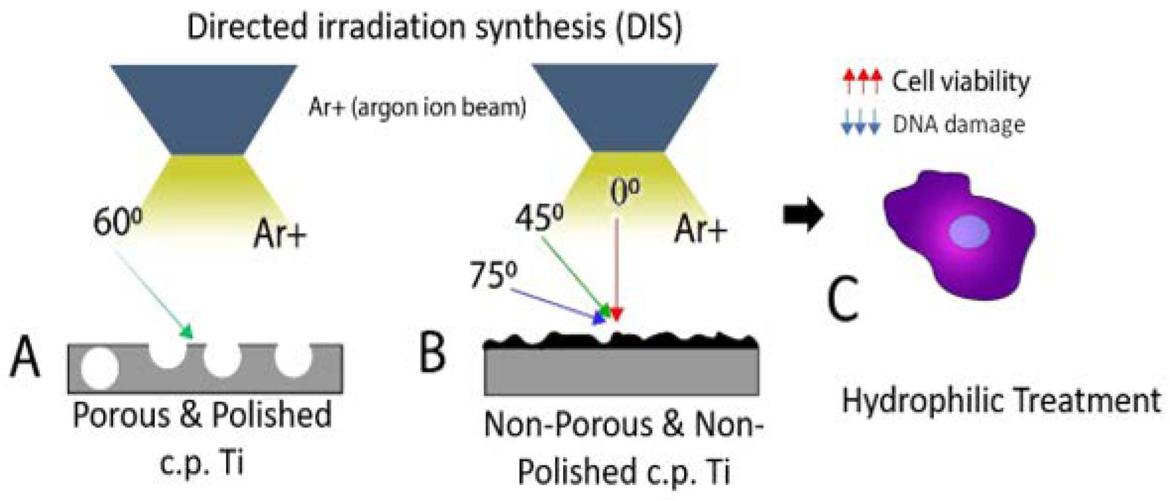
2.2. Directed Irradiation Synthesis (DIS) of Porous and Non-Porous c.p. Ti Samples

Porous c.p. Ti samples were grounded and polished before DIS exposure and denoted as “porous and polished” samples (PPS). The surface finishing was the same for the control surface non-porous and polished (c.p. Ti) than for PPS1# and PPS2# samples (porous and polished surfaces before irradiation of loose sintering and low pressure respectively) using an improved polishing protocol in our group (detailed in Supplementary Materials). In contrast, original non-porous and non-polished c.p. Ti samples referred “as-received” (NPS) were directly irradiated (e.g., no polish treatment before DIS), denoted as non-porous surfaces (NPS1, NPS2, and NPS3). DIS experiments were performed at the Radiation Surface Science and Engineering Laboratory (RSSEL) in the School of Nuclear Engineering, Purdue University, in the Particle and Radiation Interaction with Soft and Hard Matter (PRIHSM) facility, originally developed and operated by Prof. Jean Paul Allain at Purdue University [27]. DIS conditions are summarized in Table 1; Energy, fluence, and incidence angle were chosen after an exhaustive revision of our previous DIS nano-structuring results on metallic materials [33,34], as well as from some other revised works on Ti, TiO2, Cu, Au, and Ag [35,36,37,38,39,40,41,42,43,44,45]. Argon (Ar+) source at 1 and 0.5 keV was used to irradiate PPS samples and NPS; the selection of DIS parameters were designed to evaluate their effect on nanopatterning.

2.3. Structural and Surface Free Energy Characterization of c.p. Ti Samples Modified by DIS

Morphological features of samples were analyzed by scanning electron microscopy, SEM (Philips XL40 field emission, FEI, Hillsboro, OR, USA) and an optical microscope Nikon Epiphot (Nikon, Tokyo, Japan) coupled with a camera Jenoptik Progres C3 (Jenoptik, Jena, Germany). Atomic force microscopy (AFM) was also used for detailed morphological and topographical characterization of c.p. Ti surface, porous and polished surfaces without irradiation (PPS1# and PPS2#), irradiated porous and polished surfaces (PPS1 and PPS2), non-porous and non-polished (NPS) and irradiated ones (NPS1-NPS3) by using an AFM Veeco Dimension 3000 (Santa Barbara, CA, USA) on tapping mode with a DNP-10 cantilever to obtain images at scan sizes of 1 μm. Surface free energy of irradiated samples was evaluated by contact angle testing with deionized water through a Ramé-Hart Goniometer Model 500-Advanced contact angle goniometer with DROPimage Advanced Software. All measurements were performed with deionized water using the sessile drop method of 3 μL of water on each sample.

2.4. Biological Evaluation of c.p. Ti Samples Modified by DIS

Human aortic smooth muscle cells (HASMCs, Lifetechnology Cat #C0075C) are a primary human cell line used to test the in vitro cytocompatibility. Cells were cultured using culture media, Medium 231 (Thermofisher, Cat. no. M-231-500) at 37 °C, 5% CO2, and 95% humidity in 75 cm2 culture flask. Samples labeled as PPS1, NPS1, NPS2, and NPS3 were cleaned and sterilized by autoclave at 121 °C during 30 min. After that, samples were placed in a 6-well plate and HASMCs cells were seeded at a cell density of 5 × 10³ cells/cm2 with 86% of cell viability tested by Trypan blue (Thermofisher, Cat. No. 15250061). Cell morphology was evaluated by immunostaining of cell nucleus (DAPI, Thermofisher) and cell cytoskeleton (Texas Red Phalloidin, Thermofisher) of samples previously fixated using formalin 10%. Cell viability was tested by Alamarblue assay (Thermofisher) following the manufacturer’s recommendations. Briefly, at 24 h unattached cells were removed by changing the media of the samples, 100 µL of Alamarblue reagent was added and cells were incubated during 1 h 30 min. Afterwards, the fluorescence signal was read in a microplate reader (Biotek, Synergy) and the results were expressed as relative fluorescence units using c.p. Ti as a control surface for the PPS1# and PPS1 samples following the method described in a previous work [33]. At 24 h, cytotoxic experiments were performed using The Comet Assay® (cat. #4250-050-K, Trevigen, Inc., Gaithersburg, MD, USA) following manufacturer’s recommendations in order to evaluate the potential genotoxicity effects. Comet slides were stained with Green I dye and visualized using an EPI-fluorescent microscope (Nikon Eclipse 80i, Nikon Instruments Inc., Melville, NY, USA) at 10× and images were captured using a Micropublisher 5.0 RTV digital camera (Qimaging, Surrey, BC, Canada) mounted onto EPI-fluorescent microscope. Cells treated with Etoposide were used as positive control and without toxic agent as negative control.

2.5. Statistical Analyses

All experimental measurements are presented as the mean ± standard deviation. Three samples per condition were tested and each experiment was repeated three times. Statistics analysis for cell viability and cell density was performed using one-way ANOVA with Origin Pro™ 8.6 software and A p-value of <0.05 was deemed to be statistically significant. Comet assay experiments were quantified using CometScore™ software (Tri Tek Corp., Sumerduck, VA, USA) and subsequently, Pair T-test was carried out to evaluate differences between means with Origin Pro™ 8.6 software. Significance differences were expressed at p < 0.05 (*).

3. Results

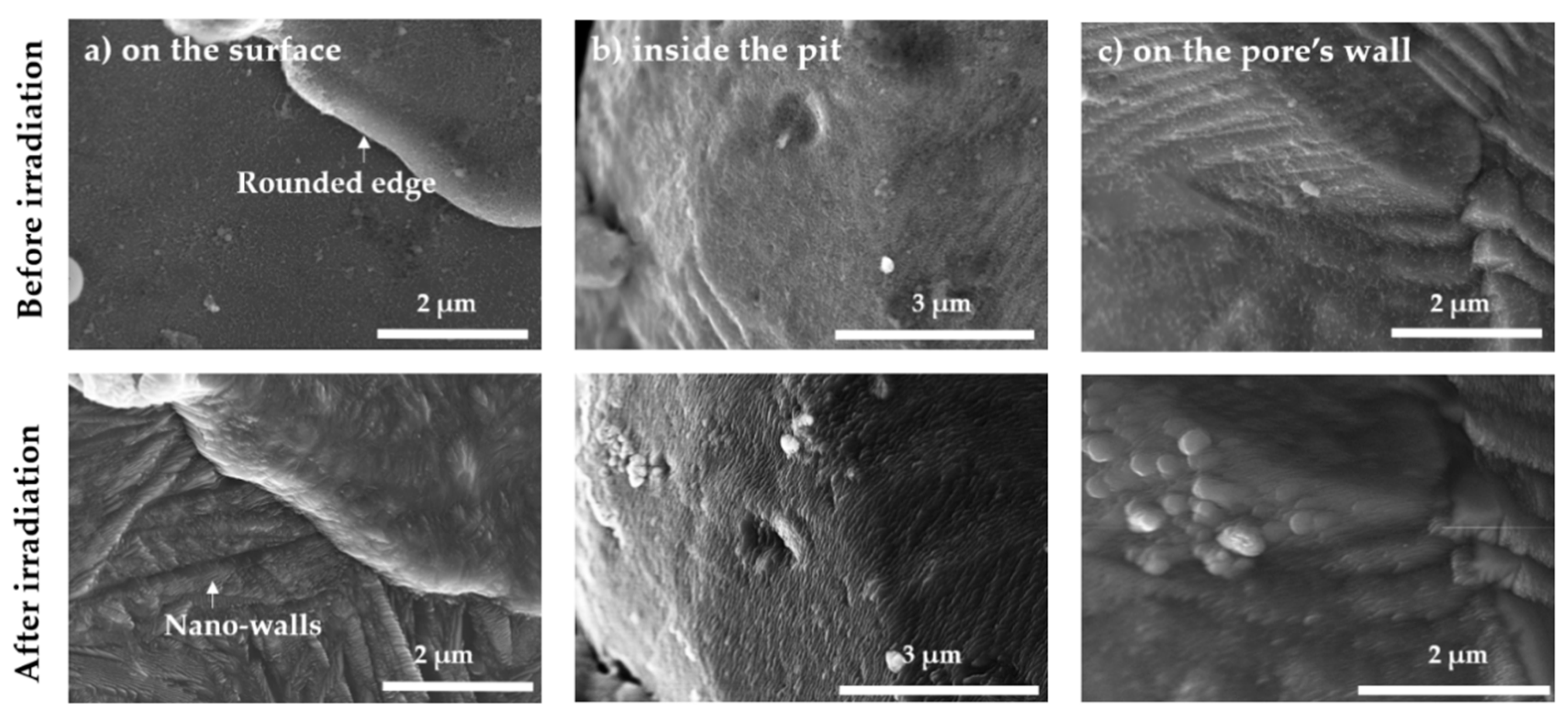
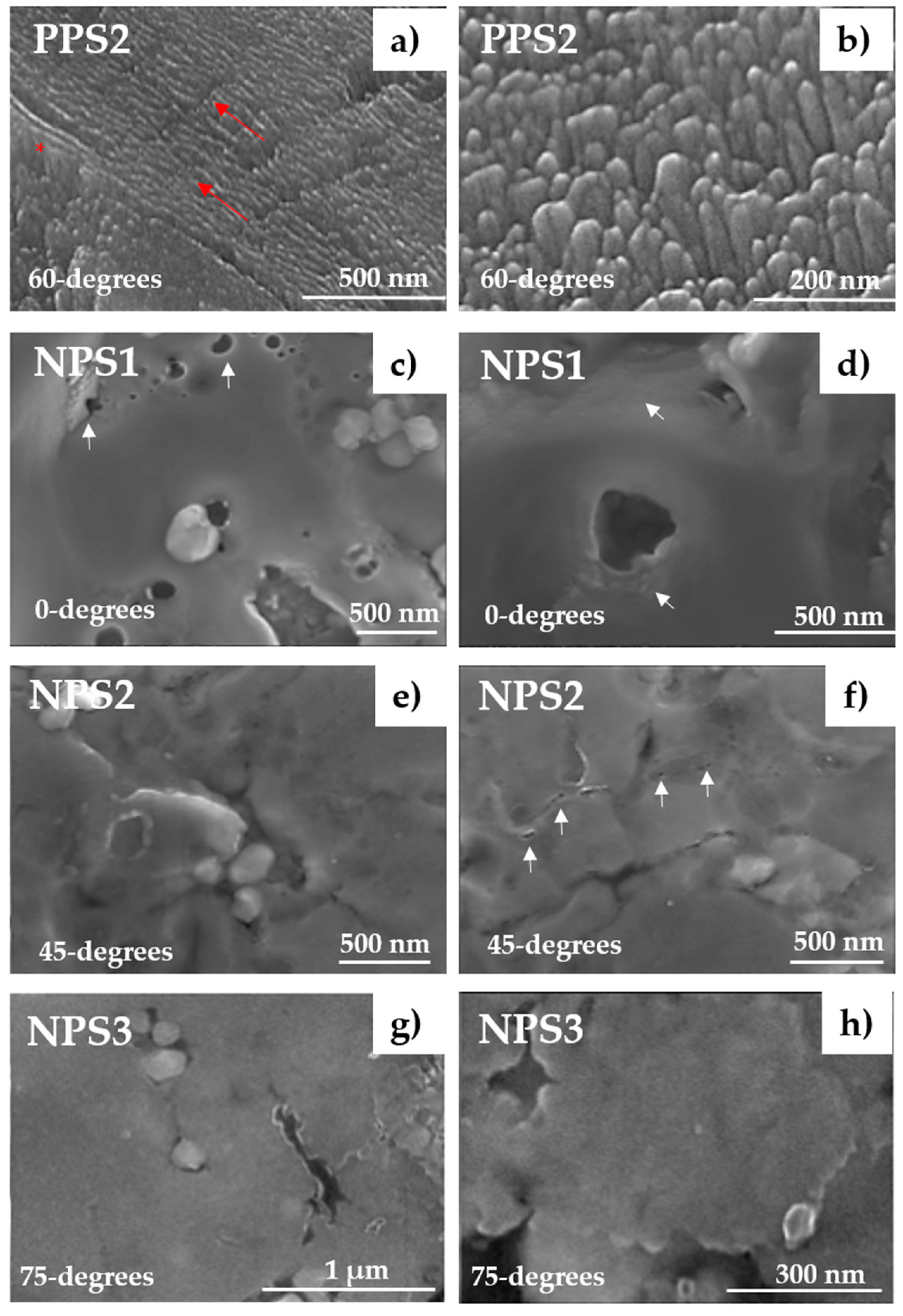
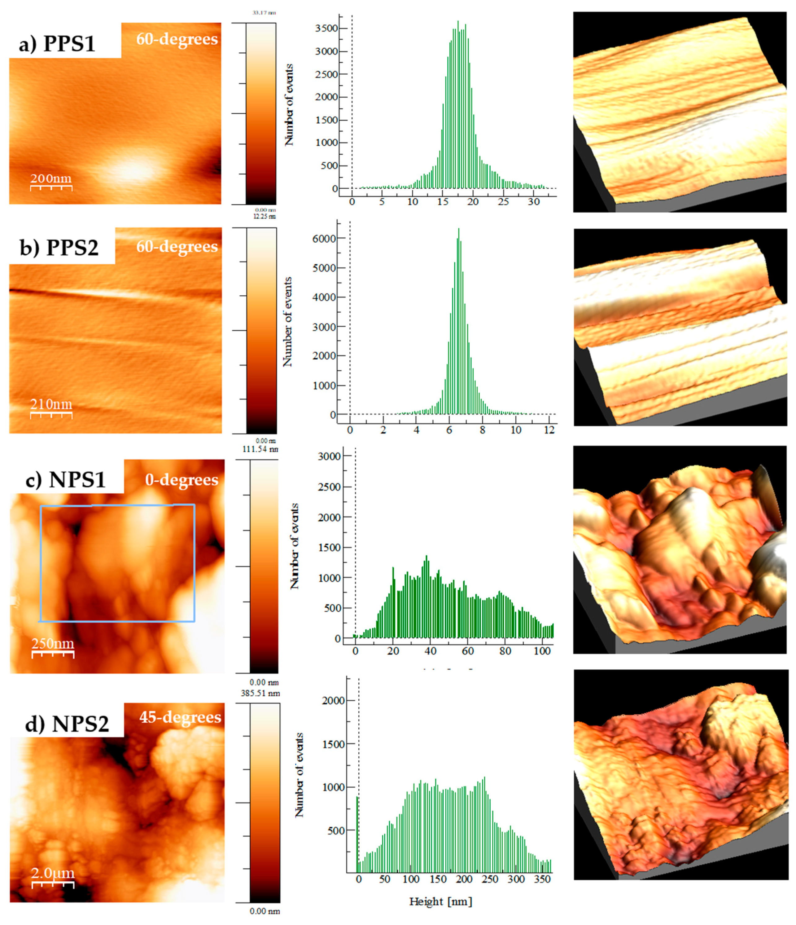
3.1. Structural Topography Characterization of As-Received (AR) and DIS Treated c.p. Ti Samples

The surface topography of “as-received” (non- porous and polished c.p. Ti, NPS) and porous and polished (PPS) substrates are shown in Figure 1. Pristine “as-received” substrate revealed a heterogeneous surface with some defects and scratches, in contrast, the surface of control c.p. Ti substrate appeared smooth and homogeneous due to the polishing treatment with some small pores due sintering process. Similarly, polished and porous pristine surfaces, PPS1# and PPS2#, presented a similar surface finishing due to the polished treatment, however, small pores of 20 to 50 µm of size were well dispersed in the entire surface.
These surfaces were also analyzed by optical microscopy to show the main differences of surface finishing before DIS modification (see Figure S1 of Supplementary Materials). The irradiation parameters used for the nanopatterning of ““as-received” and porous and polished surfaces are described in Table 1.
Two difference energies (1 and 0.5 KeV), four fluences ranging from 1.0 × 10¹⁷ to 5.0 × 10¹⁷ cgs and four incidence angles were implemented to evaluate the predominant effect on the nanopatterning by DIS.
In Figure 2, the surface structural nanomodifications due to DIS on just only one porous and polished c.p. Ti sample is summarized. Different regions of porous surface are analyzed before and after ion beam exposure observing: the surfaces between the pores (a), the surface inside the pits (b), and the surface along the internal walls of the pores (c). The influence of DIS on lower porosity c.p. Ti is manifested in a general and homogeneous nanopatterning that includes nanowalls, nanoripples, and nanorods along different regions between and within pores.
Before ion irradiation with DIS, surfaces between pores were flat due to the polishing treatment (see Figure 2a, before DIS). After DIS, the surface morphology is dominated by nanoscale walls and rods designated as “nanowalls” and “nanorods”, respectively. Nanoscale walls are approximately 100–200 nm in width and less than 10–20 nm thin and almost a micron length. Nanorods are distinguished by a conical structure where the “thickness” geometrically varies from a bottom thickness of 200 nm to a tip less than 10 nm. The structures are highly-oriented with the direction of the energetic ions from DIS and the phase of Ti material. In the images, it should be noticed the high-fidelity level of nanostructures that can be sculpted around previous mesoscale topography of porous and polished substrates along the sample surface. This is the most important advantage of DIS, the nanotopography can be sculpted in the “as-is” complex geometrical features of a Ti-based material surface.
Inside the pit surfaces, shown in Figure 2b, these “porous” Ti material present an intrinsic hierarchy of mesoscale topography in which the internal walls have the highest percentage “line of sight” of incident energetic DIS particles inducing surface nanopatterning. In this case, highly-oriented self-organized nanowall features are dispersed through the entire pit surface. In contrast, as shown in Figure 2c, along the internal walls of the pores where there is a lower percentage of “line of path” projection for the incident DIS ions, a complex mixture of nanowall structures and nanorods with rounded peaks were observed. These nanofeatures appear on both sides of the pore wall. However, the characteristic nanostructures are different on both sides of the pore wall (note only one side is shown in Figure 2c). This corresponds to the fact that the “line of sight” region exposed to the incident energetic Ar+ ions from first impact results in one type of nanostructure (e.g., nanowalls) and the “hidden surface” region in a different topography closer to a nanorod structure. The secondary collisions are therefore correlated to reflected (e.g., backscattered) energetic Ar atoms with a reflected energy that now drives a different nanostructure due to a change of incident angle, energy and flux to that secondary surface.
Considering this behavior, a detailed surface evaluation was performed varying different conditions such as fluence, energy, and angle-of-incidence on different surface finishing substrates (with or without polishing process) to analyze DIS impact on nanopatterning. Figure 3 showed the SEM images of porous and polished surfaces (PPS2) and “as-received” (NPS1-3) irradiated with different angles, 60, 0, 45 and 75 angle-of -incidence respectively. The 60-degrees incidence yielded the strongest self-organized nanofeatures compared to NPS 1-3 surfaces keeping constant Ar+ species and similar low energy.
DIS surface modification on porous and polished surfaces mostly corresponded to short rounded and oriented nanorods, (see Figure 3a). PPS2, after DIS modification, revealed similar nanotopography (in terms of geometry and size) than PPS1 which confirm the low impact of fluence parameter (1 to 2.5 × 10¹⁷ cgs) on surface nanopatterning. Regarding PPS2 surface, it is noteworthy that some nanorods demonstrated a change of direction as shown in Figure S2 of Supplementary Materials. This type nanopatterning appears to have nanoripples or a mixed structure of nanorods and nanoripples. The coherency between nanorods, nanowalls, and nanoripples with respect to ion beam direction implies a possible correlation to surface crystallographic texture. That is, a topography linked to the preferential orientation of grains along a specific direction, seemingly more prevalent for “polished” microstructures compared to “as-is” non-polished surfaces. However, although ion-beam nanopatterning with DIS has been first observed on polished Ti alloy substrates, evidence of nanopatterning inside the Ti pores and even within intrinsic surface defects (e.g., such as a scratch on the substrate) demonstrated the broad versatility of DIS as a surface modification strategy (see Figure S2 of Supplementary Materials). In addition, not only nanorods but also nanowalls are formed inside mesoscale surface defects and in the internal pore walls. The columns that protrude from the bottom of the intrinsic surface scratch seem to grow perpendicular to the surface.
On the other hand, NPS1-NPS3 surfaces were treated by DIS with a variety of incidence angles, in order to examine the influence on surface nanopatterning. Low-energy of Ar+ ion beams with normal and off-normal incidences (0°, 45°, and 75°) where observed in Figure 3c–h respectively. Surface topography of the three different angles was similar at the micro-scale level compared to the untreated surface (see Figure 1a,e). On NPS1, areas of nanoholes (marked by white arrows) were presented in the sample before irradiation, however, after DIS these nanoholes were rounded by a slightly nanoripples formation. Different sizes of pores can be detected probably due to the non-homogeneous surface and the removal of artifacts due to Ar+ ion beam exposure (see white arrows). In contrast, off-normal incidence using 45° and 75° (see Figure 3e–h) NPS2 and NPS3, resulted in different topography. The microscale surface was similar to NPS1 samples, however, at the highest magnification images (see Figure S3 of Supplementary Materials) there were no appreciable nanoscale features due to off-normal DIS, and in fact, surfaces appeared smoother, opposite from the non-porous NPS1 sample. It was observed a decrease of protrusions showing a smoothening effect after Ar+ ion irradiations. Notice this observed phenomenon even higher for the increased off-normal incidence (75°), (see Figure S3g–i of Supplementary Materials).
Surface roughness quantification was performed by AFM compiling the results in Table 2 and the 3D reconstruction and height measurements in Figure 4. AFM images of PPS samples verified the nanopatterning modification previously observed by SEM, however, it was difficult to distinguish mixed features at the nanoscale level (nanorods and nanoripples). From Table 2, the nominal mean rms roughness was 0.57 nm and 3.49 nm for PPS1 (high porosity) and PPS2 (low porosity), respectively (Figure 4a,b). These results confirm the increased roughness effect after DIS compared to the non-irradiated counterparts PPS1# and PPS2# (with an initial roughness of 0.32 nm and 0.08 nm, respectively). On PPS2, the presence of micro-scratches, as noted earlier in SEM images, were identified likely due to mechanical polishing during sample preparation.
Non-porous and non-polished samples after irradiation with 0°, and 45° incidence angles (NPS1 and NPS2) present higher roughness values with respect to the irradiated porous PPS1 and PPS2 samples as it is observed in Figure 4c,d respectively. Notice that mean rms roughness of NPS1 and NPS2 are similar and higher than NPS3 (shown in Table 2). AFM analysis of NPS3 demonstrated the lack of nanopatterning effect and the reduction of roughness and mean height values highlighting the previous smoothening effect observed in SEM and reported in previous similar works [46]. The decreased of roughness value in NPS3 was notably lower, 22.07 nm and 55.42 nm compared to the normal incident angle (NPS1). This smoothening effect at grazing incidence angles were also observed in SEM images where no nanoholes were detected as well as the clear absence of any roughening debris. It should be noted that the interpretation of AFM measurements of such complex topography is complicated. Given the high-fidelity control of surface topography and the intrinsic high-aspect ratio nature of the nanopatterns formed with DIS, AFM may only capture only partially the nanopattern characteristics. For example, the AFM data are obtained in tapping mode and as such will be limited to only capture the first 10s of nm of the fabricated nanowalls, where the depth is the order of 100s of nm by SEM.

3.2. Surface Free Energy Evaluation of As-Received (AR) and Porous DIS Treated c.p. Ti Samples

Human blood contains approximately 90% water, thus the capability of water adsorption by the surface, also known as wettability, is a fundamental parameter that influences cells interactions at the biointerface of titanium–bone tissue [47]. The biological cascade of events that takes place can be modulated by the implant surface properties (chemistry and nanotopography). The contact angle of “as-received” and non-porous and polished control (c.p. Ti) samples resulted in values of 65.96 ± 4.3 and 53.03 ± 0.06 degrees (see Table 2), which is in agreement with other results reported in previous studies in our group [48] and from other authors such as Riedel and coworkers [49]. Before DIS, the control polished and porous surfaces (PPS1# and PPS2#) showed similar contact angle values described for c.p. Ti of 51.0 ± 2.7 and 55.4 ± 3.1 degrees respectively. However, PPS1 and PPS2 showed a notable reduction of contact angle values, likely associated with the nanopatterning formation by DIS, confirming the increase hydrophilicity character of this surface modification (see Table 2). The contact angle values observed for PPS1 was 13.4 ± 4.5 and for PPS2 was 28.1 ± 5.2 degrees which supposed a reduction 73.65% and 49.32% respectively compared to PPS1# and PPS2# control surfaces. The contact angles of irradiated non-porous samples, NPS1, NPS2, and NPS3 were also lower than NPS control surface observing a reduction of 49.51%, 51.33% and 61.18% respectively. As a result, both types of substrates demonstrated an increased in the hydrophilicity character of the surface after DIS modification.

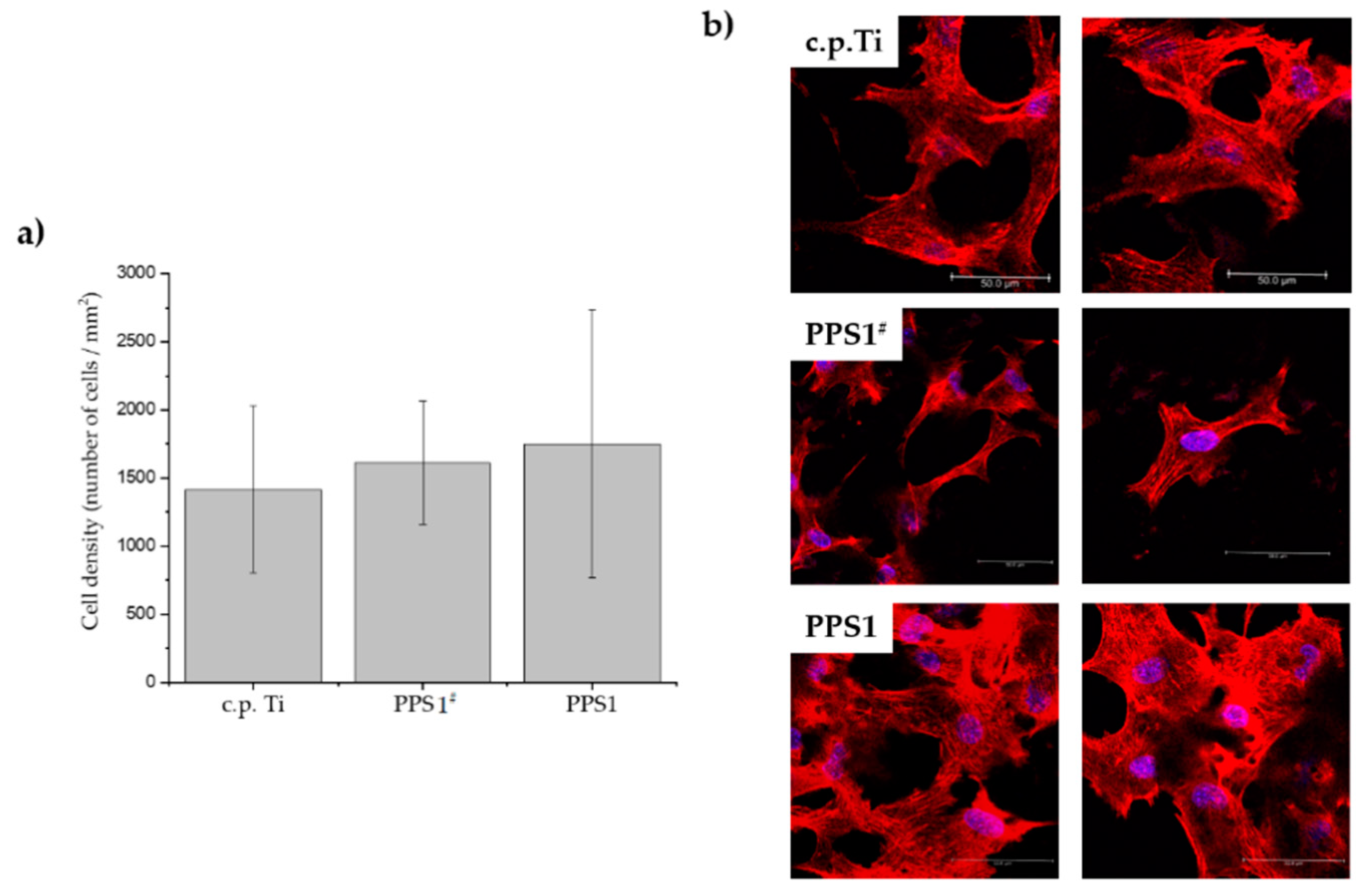
3.3. Biological Assessment of c.p. Ti Samples

Figure 5 shows the cell metabolic activity assessment on c.p. Ti, PPS1# and PPS1 substrates as an example of the different specimens using Alamarblue assay at two different time points.
Although human aortic smooth muscle cells (HASMCs) were able to attach to all studied surfaces: c.p. Ti, PPS1# and PPS1, at 1 day higher cellular metabolism was observed on c.p. Ti. This higher metabolism was statistically significance compared to PPS1# and PPS1 surfaces which was due to the absence of pore in c.p. Ti structure. However, when the comparison is made with and without DIS modification the cell viability levels are notably superior in PPS1#. In terms of cell viability percentage, at day 1 the PPS1 substrate reached 80.26% highly superior to 59.09% of PPS1# control surface considering c.p. Ti as 100% of cell viability. These levels confirmed the positive effect of the nanotopography at early stages of cell attachment. At day 7, similar cellular metabolism is observed in the three studied surfaces reaching more than 84% and 87% of cell viability on PPS1# and PPS1 surfaces, respectively. Therefore, this level revealed the potential safety and cytocompatibility of DIS treatment on adhesion and proliferation of HASMCs.
In Figure 6, cell density and cell morphology results of HASMCs growing at day 1 are presented. Even though similar cell density was observed for the three surfaces, actin fiber formation was superior on PPS1 compared to control surfaces (Figure 6b). HASMCs attached on PPS1 displayed an advanced cytoskeleton with higher cell surface area in contact with the titanium substrate, as compared to a reduced cell area on PPS1#.
Subsequently, Comet Assay® testing was performed to evaluate the potential geno-toxicological effect in in vitro conditions on HASMCs compiling the results in Figure 7. Figure 7a shows the characteristic shape of nucleoid exhibiting damaged DNA (head and the tail) for all Ti samples. As it is observed in PC (positive control), the tail of the nucleoid corresponds to DNA strand breaks produced by exposure with the toxic agent H2O2 which is an indicative of the cytotoxic effect. However, there was no damaged DNA in untreated cells (NC, negative control) which showed compact nucleoids without any tail. c.p. Ti, NPS1, NPS2 and PPS1 showed no DNA strand breaks and a well-defined and round nucleoid (head part). These nucleoid shapes are closer to NC sample instead of the PC. The potential damaged DNA produced on HASMCs after exposure to the tested analytes was quantified using Comet Score™ software (Tri Tek Corp., Sumerduck, VA, USA). Positive results for damaged DNA are characterized for a high percentage of DNA in tail close or higher than the values for the PC sample. One way-ANOVA analyses confirmed that porous and non-porous Ti samples were significantly different (* p < 0.05) compared to PC as it is observed in Figure 7b,c, thus indicates no detrimental effects in HASMC’s DNA growing on the DIS surfaces. The range of variation for the tested samples is lower than the positive control (treated with H2O2). It confirms that irradiation process with argon into c.p. Ti surfaces did not induce DNA damage on HASMCs cultured in the presence of these materials.

4. Discussion

Nanofeatures of porous c.p. Ti samples depicted in Figure 2 and Figure 3 are consistent with some previous studies about Ar+ ion beam irradiation on c.p. Ti [34]; similar to that work, mostly nanorods and some mixed areas with nanoripples for an incidence angle of 60° were obtained. This similar effect is due to a slightly higher incidence angle than transition angle (TA) between nanoripples formation (normal incidence) and straight and long nanorods (highly off-normal incidence). The high nanopatterning effectiveness observed due to DIS on porous and polished c.p. Ti (100% α phase, hcp), is in agreement with a previous work of the authors about DIS on Ti6Al4V [34], and with other similar studies [36,50]. The combination of flat and porous surface areas seems not to mean any obstacle to DIS efficiency for surface nanopatterning of c.p. Ti. The presence of nanofeatures inside of pores responds to the interactions between remote (nominal) incidence angle (60°) and local incidence angles inside the pores; in this context, flat polish areas responded in a conventional mixed of nanorods and nanoripples. However, curved zones inside the pores are more sensitive to create nanorods, which is related to the erosive regime of Ar+ ions under an intermediate incidence angle (60°).
From the theoretical point of view, the first advances in ion beam sputtering (IBS) to understand nano-structuring was made by Sigmund et al. [51]. He showed that local surface minima (“valleys”) should be eroded at a faster rate than local maxima (“peaks”); i.e., the sputtering rate depends on the local surface curvature, leading to a surface instability, which is the origin of the nano-structuring process. Based on this work, Bradley and Harper (BH) proposed the first model describing nanoripples formation [52]. In that sense, sputtering process is used to modify the surface topography due to its dependence on the local surface curvature [53]. Depending on the irradiation conditions (incidence angle, energy, surface curvature, etc.), it can induce either surface smoothening or roughening. These competing processes may be used to design the surface geometry required for certain applications. In case of metallics biomaterials, the build-up of a regular pattern is produced by two different mechanisms, which led to a similar surface instability. On one hand, the surface curvature dependence of the ion sputtering and on the other hand the presence of an extra energy barrier whenever diffusing adatoms try to descend step edges. Inside the pores, several incidence angles can take place for a fixed remote incidence angle and this effect shows a relationship between pore curvature and surface nanopatterning. Therefore, the patterns inside the pores using off-normal ion incidence angles (such as 60°) can be predicted, ideally with a semi-circular pore with a diameter similar to the grain size: 1. Initially, a nanorods area is produced due to a semi-grazing incidence, which is associated with a predominant erosive regime. 2. A second area consists of a mixed pattern of rods, walls, and ripples due to its similarity with remote conditions using 60° incidence (diffusive plus erosive regimes). 3. A nanorippled area appears under normal incidence conditions (diffusive regime). 4. Once again, a mixed of nanorods and nanoripples zone was developed due to the occurrence of a local incidence angle similar to off-normal remote angle. Notice that some pores in Figure 2 and Figure S2 of Supplementary Materials appear mostly with nanowalls inside, related to a certain prevalence of erosive conditions.
Therefore, the existence of nanoripples is not surprising for c.p. Ti under normal incidence on a flat surface because they are normally associated with the diffusive regime. In fact, other authors have already reported this phenomenon. Quian et al. [36] observed 100% of nanoripples on c.p. Ti grains when they applied Focused ion beam (FIB) technique using Ga+ ions and normal incidence angle on c.p. Ti previously polished. Furthermore, Riedel et al. [50] also described nanoripple formation on “as-received” Ti6Al4V substrates, using normal incidence angle and Ar+ ions with different levels of low energy, observing a partial nanoripples and small holes related to an etching effect of ion bombardment. In order to explain our results under normal incidence, surface curvature of the irradiated substrate plays a critical role in the final nanopatterning; therefore, for “as-received” (NPS) surfaces with a vertical roughness of around 20 to 300 nm, it is hardly expected any effect of diffusive regime on the surface in concordance with BH model prediction. In contrast, lower vertical roughness observed in flat surfaces of round 5 nm effectively ensures a high nanopatterning response due to ion incidence.
In addition, there are two other factors that can avoid effective nanorippling during Ar+ normal incidence on “as-received” (NPS) surfaces: first, crystalline phase is not directly exposed to broad ion beam; then, this is a clear obstacle to any atom diffusion driving force due to impacting ions; and second irregularities associated to roughness can clearly allow an interference phenomenon between protrusions, which will reduce any driving diffusion nanopatterning effect. Nanoscale holes observed in normal incidence angle are related with increased roughness, which increases the erosive effect. The nanoholes formation was reported by Li et al. [54] using Ar+ ions and normal incidence angle on a thin solid-state membrane with big pores and irradiated areas. In this study, the ion beam removed the thin neck between the big pores and the irradiated part producing the nanoholes. Therefore, our nanoholes on “as-received” NPS samples are the consequence of a big pore or valley below a thin irradiated layer.
According to the AFM results, nanopatterning aspect of lower and higher porosity samples are similar, however, roughness values are higher on PPS2 which was irradiated using higher energy. These results were validated in other reports, although, they measured different AFM conditions. [36] As it was expected, “as-received” samples reached higher RMS values because there was no previous polish treatment. Nevertheless, the roughness decreased using off-normal incident angles of 75° which was in agreement with other authors. Hino et al. [46] observed this tendency using Ar+ irradiation on highly pure Cu describing a smoother surface on incidence angle of 70°. Hence, the ion bombardment can be used to alter the surface morphology due to its relationship with local surface curvature [53]. The smoothened effect can be attributed to a lost balance of the factors that control nanopatterning process. According to BH model [52], smoothing effect prevails in order to re-establish the balance, therefore, small irregularities on a relatively smooth surface may result enhanced by ion bombardment.
Regarding the wettability of the surface, DIS modification reduced contact angle values on porous and non-porous substrates compared to Ti controls (c.p. Ti, PPS1#, PPS2#, and NPS) confirming the hydrophilicity treatment of the irradiation process. This reduction of contact angle was independent of the roughness modification as it was observed in NSP1, NSP2, and NSP3. This behavior is explained by the relationship of contact angle factors and the surface free energy. Different mechanisms of molecular interactions between water and a surface (i.e., covalent bonding, electrostatic and electromagnetic interactions [49,55] intervenes in the balance of free energies and the subsequent surface tension related to each interface (solid–liquid, liquid–gas, gas–solid). Two models have been developed based on modifications to Young’s equation; these are the Wenzel [56] and the Cassie–Baxter models [57]. In Wenzel regime, the liquid totally contacts to the solid rough surface. In contrast, Cassie–Baxter model assumes that roughness of the surface prevents full contact between the liquid and solid by trapping gas between the two phases. According to these models, contact angle depends on several factors such us on: liquid properties, contact time, environmental temperature and pressure and surface topographical and chemical parameters (surface chemistry, crystalline structure and crystalline defects, surface residual stress and surface micro-curvature). Within this framework the following Figure 8 shows the relationship between the DIS incidence angle irradiation with surface properties (roughness and contact angle).
Previously to DIS modification, PPS samples were polished on flat areas and this affected the nanopatterning process. The increased roughness on PPS1 and PPS2 influenced the lower contact angles. These results showed the influence of DIS modifications (nanostructuring and surface chemistry) satisfying the Wenzel regime.
Compared to previous works about the biological assessment of Ar+ irradiated Ti samples, cell viability are in agreement with those reported in c.p. Ti II after normal incidence [48], which showed an increase in pre-osteoblasts cell proliferation on irradiated samples compared to the untreated surfaces. In addition, they observed an improved cell viability and cell morphology on irradiated titanium samples after argon-ion irradiation. Cell biocompatibility reached on irradiated samples is, at least, equal or superior to the well-known biocompatibility of conventional bio-inert c.p. Ti without DIS (c.p. Ti, PPSC); therefore, DIS surface modification treatment allow tailoring the nanofeatures, roughness and wettability desired to improve cell viability on different surface microtopography (polished, porous, and “as-received” Ti substrates).

5. Conclusions

Surface characterization and preliminary biological evaluation of porous and polished (PPS) and “as-received” (NPS) commercially pure titanium substrates were studied after DIS treatment increasing the surface roughness on porous and polished substrates while “as-received” showed a smoothening effect on off-normal incidence angle. Different ranges of fluence achieved similar nanopatterning on porous and polished structures while a general increased of hydrophilicity was observed in all irradiated surfaces. This surface modification allowed cell adhesion and proliferation without reducing cell viability or damaging cell DNA. DIS open a new insight for the development of nanopattern surfaces by just modifying the intrinsic properties of the pristine materials in order to enhance the biocompatibility. Future research steps will include the role of other irradiation parameters among the incidence angle such as gas species, current density, and the presence of metallic impurities that can trigger their instability to produce spontaneous self-organized nanostructures. Finally, surface chemistry evaluation by XPS will provide the elemental composition due to DIS.

Supplementary Materials

The following are available online at https://0-www-mdpi-com.brum.beds.ac.uk/2075-4701/9/12/1349/s1. Figure S1. Evaluation of the different surface finishing of c.p. Ti samples before DIS modification. (a) SEM images of “as received”, c.p.Ti, PPS1# and PPS2# substrates respectively. (b) Optical microscopy images performed with a Nikon Epiphot (Nikon, Tokyo, Japan) coupled with a camera Jenoptik Progres C3 (Jenoptik, Jena, Germany) before DIS treatment. Figure S2. SEM images of different areas of porous and polished c.p. Ti surface (PPS2) after the irradiation of Argon ions by DIS. White arrows indicate the presence of nanocolumns or nanorods (f) and nanowalls in the same area (g). Figure S3. SEM images of different areas of non-porous as received surfaces after the irradiation of Argon ions by DIS using different incidence angles. (a) to (d) images correspond to NPS1, (e) and (f) represent NPS2, and NPS3 are (g) to (i) images. The white arrows point out the detail of rough surface in (a), nanoholes in (b) and smoother substrate in (g).

Author Contributions

Conceptualization, methodology, project administration and funding acquisition: J.J.P., J.A.R.-O., Y.T. and J.P.A. Validation, formal analysis, investigation, and data curation: A.C., S.L.A., E.W., A.S. Discussion and writing—the original draft, review and editing, A.C., J.P.A., J.J.P., A.S., O.E.-A., E.W., S.L.A., E.G., J.A.R.-O., M.C., and Y.T.

Funding

This research was funded by the Department of Defense under contract W81XWH-11-2-0067, and the Ministry of Economy and Competitiveness of Spain, grant number MAT2015-71284-P.

Acknowledgments

The authors would like to thank the Department of Defense and the Ministry of Economy and Competitiveness of Spain for their financial support. The research facilities where this study has been performed: Frederick Institute (Materials Research Lab), Micro and Nanotechnology Lab, and Beckman Institute of University of Illinois at Urbana-Champaign. This article is also dedicated to our dear friend and colleague Juan Jose Pavón, who prematurely passed away early in 2017, his dedication to his work, his students, his friends and family, will always be remembered.

Conflicts of Interest

The authors declare no conflict of interest.

References

  1. Nazarian, A.; von Stechow, D.; Zurakowski, D.; Müller, R.; Snyder, B.D. Bone volume fraction explains the variation in strength and stiffness of cancellous bone affected by metastatic cancer and osteoporosis. Calcif. Tissue Int. 2008, 83, 368–379. [Google Scholar] [CrossRef] [PubMed]
  2. Albrektsson, T.; Johansson, C. Osteoinduction, osteoconduction and osseointegration. Eur. Spine J. 2001, 10, 96–101. [Google Scholar]
  3. Busscher, H.J.; Van Der Mei, H.C.; Subbiahdoss, G.; Jutte, P.C.; Van Den Dungen, J.J.; Zaat, S.A.; Schultz, M.J.; Grainger, D.W. Biomaterial-associated infection: Locating the finish line in the race for the surface. Sci. Transl. Med. 2012, 4. [Google Scholar] [CrossRef] [PubMed] [Green Version]
  4. Coelho, P.G.; Jimbo, R.; Bonfante, E.A. Experimental and clinical knowledge of nanometer scale designing on endosteal implants. In Implant Surfaces and Their Biological and Clinical Impact; Springer: Berlin/Heidelberg, Germany, 2015; pp. 29–43. [Google Scholar]
  5. Koldsland, O.C.; Scheie, A.A.; Aass, A.M. Prevalence of peri-implantitis related to severity of the disease with different degrees of bone loss. J. Periodontol. 2010, 81, 231–238. [Google Scholar] [CrossRef]
  6. Materials Surface Effects on Biological Interactions|SpringerLink. Available online: https://0-link-springer-com.brum.beds.ac.uk/chapter/10.1007/978-90-481-8790-4_12 (accessed on 29 October 2018).
  7. Parthasarathy, J.; Starly, B.; Raman, S.; Christensen, A. Mechanical evaluation of porous titanium (Ti6Al4V) structures with electron beam melting (EBM). J. Mech. Behav. Biomed. Mater. 2010, 3, 249–259. [Google Scholar] [CrossRef]
  8. Oppenheimer, S.M.; Dunand, D.C. Porous NiTi by creep expansion of argon-filled pores. Mater. Sci. Eng. A 2009, 523, 70–76. [Google Scholar] [CrossRef]
  9. Chino, Y.; Dunand, D.C. Directionally freeze-cast titanium foam with aligned, elongated pores. Acta Mater. 2008, 56, 105–113. [Google Scholar] [CrossRef]
  10. Ryan, G.E.; Pandit, A.S.; Apatsidis, D.P. Porous titanium scaffolds fabricated using a rapid prototyping and powder metallurgy technique. Biomaterials 2008, 29, 3625–3635. [Google Scholar] [CrossRef]
  11. Krishna, B.V.; Bose, S.; Bandyopadhyay, A. Low stiffness porous Ti structures for load-bearing implants. Acta Biomater. 2007, 3, 997–1006. [Google Scholar] [CrossRef]
  12. An, Y.B.; Oh, N.H.; Chun, Y.W.; Kim, Y.H.; Kim, D.K.; Park, J.S.; Kwon, J.J.; Choi, K.O.; Eom, T.G.; Byun, T.H. Mechanical properties of environmental-electro-discharge-sintered porous Ti implants. Mater. Lett. 2005, 59, 2178–2182. [Google Scholar] [CrossRef]
  13. Orru, R.; Licheri, R.; Locci, A.M.; Cincotti, A.; Cao, G. Consolidation/synthesis of materials by electric current activated/assisted sintering. Mater. Sci. Eng. R Rep. 2009, 63, 127–287. [Google Scholar] [CrossRef]
  14. Torres, Y.; Pavón, J.J.; Nieto, I.; Rodríguez, J.A. Conventional powder metallurgy process and characterization of porous titanium for biomedical applications. Metall. Mater. Trans. B 2011, 42, 891–900. [Google Scholar] [CrossRef]
  15. Torres, Y.; Lascano, S.; Bris, J.; Pavón, J.; Rodriguez, J.A. Development of porous titanium for biomedical applications: A comparison between loose sintering and space-holder techniques. Mater. Sci. Eng. C 2014, 37, 148–155. [Google Scholar] [CrossRef] [PubMed]
  16. Wen, C.E.; Mabuchi, M.; Yamada, Y.; Shimojima, K.; Chino, Y.; Asahina, T. Processing of biocompatible porous Ti and Mg. Scr. Mater. 2001, 45, 1147–1153. [Google Scholar] [CrossRef]
  17. Oh, I.-H.; Nomura, N.; Masahashi, N.; Hanada, S. Mechanical properties of porous titanium compacts prepared by powder sintering. Scr. Mater. 2003, 49, 1197–1202. [Google Scholar] [CrossRef]
  18. Boyan, B.D. Modulation of osteogenesis via implant surface design. In Bone Engineering; EM Squared Incorporated: Toronto, ON, Canada, 2000; pp. 232–239. [Google Scholar]
  19. Boyan, B.D.; Cheng, A.; Olivares-Navarrete, R.; Schwartz, Z. Implant surface design regulates mesenchymal stem cell differentiation and maturation. Adv. Dent. Res. 2016, 28, 10–17. [Google Scholar] [CrossRef]
  20. Dalby, M.J.; Gadegaard, N.; Tare, R.; Andar, A.; Riehle, M.O.; Herzyk, P.; Wilkinson, C.D.; Oreffo, R.O. The control of human mesenchymal cell differentiation using nanoscale symmetry and disorder. Nat. Mater. 2007, 6, 997–1003. [Google Scholar] [CrossRef]
  21. Dalby, M.J. Cellular response to low adhesion nanotopographies. Int. J. Nanomed. 2007, 2, 373–381. [Google Scholar]
  22. Biggs, M.J.P.; Richards, R.G.; Dalby, M.J. Nanotopographical modification: A regulator of cellular function through focal adhesions. Nanomed. Nanotechnol. Biol. Med. 2010, 6, 619–633. [Google Scholar] [CrossRef] [Green Version]
  23. Hart, M.; Lauer, J.; Selig, M.; Hanak, M.; Walters, B.; Rolauffs, B. Shaping the Cell and the Future: Recent Advancements in Biophysical Aspects Relevant to Regenerative Medicine. J. Funct. Morphol. Kinesiol. 2018, 3, 2. [Google Scholar] [CrossRef] [Green Version]
  24. Abagnale, G.; Steger, M.; Nguyen, V.H.; Hersch, N.; Sechi, A.; Joussen, S.; Denecke, B.; Merkel, R.; Hoffmann, B.; Dreser, A.; et al. Surface topography enhances differentiation of mesenchymal stem cells towards osteogenic and adipogenic lineages. Biomaterials 2015, 61, 316–326. [Google Scholar] [CrossRef] [PubMed]
  25. Sjöström, T.; Dalby, M.J.; Hart, A.; Tare, R.; Oreffo, R.O.; Su, B. Fabrication of pillar-like titania nanostructures on titanium and their interactions with human skeletal stem cells. Acta Biomater. 2009, 5, 1433–1441. [Google Scholar] [CrossRef]
  26. Tripathy, A.; Sen, P.; Su, B.; Briscoe, W.H. Natural and bioinspired nanostructured bactericidal surfaces. Adv. Colloid Interface Sci. 2017, 248, 85–104. [Google Scholar] [CrossRef] [PubMed]
  27. Allain, J.P.; Nieto, M.; Hendricks, M.R.; Plotkin, P.; Harilal, S.S.; Hassanein, A. IMPACT: A facility to study the interaction of low-energy intense particle beams with dynamic heterogeneous surfaces. Rev. Sci. Instrum. 2007, 78, 113105. [Google Scholar] [CrossRef] [PubMed] [Green Version]
  28. Schernthaner, M.; Reisinger, B.; Wolinski, H.; Kohlwein, S.D.; Trantina-Yates, A.; Fahrner, M.; Romanin, C.; Itani, H.; Stifter, D.; Leitinger, G. Nanopatterned polymer substrates promote endothelial proliferation by initiation of β-catenin transcriptional signaling. Acta Biomater. 2012, 8, 2953–2962. [Google Scholar] [CrossRef] [PubMed]
  29. Tserepi, A.; Gogolides, E.; Bourkoula, A.; Kanioura, A.; Kokkoris, G.; Petrou, P.S.; Kakabakos, S.E. Plasma nanotextured polymeric surfaces for controlling cell attachment and proliferation: A short review. Plasma Chem. Plasma Process. 2016, 36, 107–120. [Google Scholar] [CrossRef]
  30. Sjöström, T.; McNamara, L.E.; Meek, R.D.; Dalby, M.J.; Su, B. 2D and 3D nanopatterning of titanium for enhancing osteoinduction of stem cells at implant surfaces. Adv. Healthc. Mater. 2013, 2, 1285–1293. [Google Scholar] [CrossRef]
  31. Lu, J.; Rao, M.P.; MacDonald, N.C.; Khang, D.; Webster, T.J. Improved endothelial cell adhesion and proliferation on patterned titanium surfaces with rationally designed, micrometer to nanometer features. Acta Biomater. 2008, 4, 192–201. [Google Scholar] [CrossRef]
  32. ASTM F67-00 (2002). Standard Specification for Unalloyed Titanium for Surgical Implant Applications; American Society for Testing and Materials: Philadephia, PA, USA, 2002. [Google Scholar]
  33. Civantos, A.; Barnwell, A.; Shetty, A.R.; Pavón, J.J.; El-Atwani, O.; Arias, S.L.; Lang, E.; Reece, L.M.; Chen, M.; Allain, J.P. Designing Nanostructured Ti6Al4V Bioactive Interfaces with Directed Irradiation Synthesis toward Cell Stimulation to Promote Host—Tissue-Implant Integration. ACS Biomater. Sci. Eng. 2019, 5, 3325–3339. [Google Scholar] [CrossRef]
  34. Allain, J.P.; Shetty, A. Unraveling atomic-level self-organization at the plasma-material interface. J. Phys. D Appl. Phys. 2017, 50, 283002. [Google Scholar] [CrossRef]
  35. Chan, W.L.; Pavenayotin, N.; Chason, E. Kinetics of ion-induced ripple formation on Cu(001) surfaces. Phys. Rev. B 2004, 69. [Google Scholar] [CrossRef]
  36. Qian, H.X.; Zhou, W. Self-organization of ripples on Ti irradiated with focused ion beam. Appl. Surf. Sci. 2012, 258, 1924–1928. [Google Scholar] [CrossRef]
  37. Busse, C.; Engin, C.; Hansen, H.; Linke, U.; Michely, T.; Urbassek, H.M. Adatom formation and atomic layer growth on Al (1 1 1) by ion bombardment: Experiments and molecular dynamics simulations. Surf. Sci. 2001, 488, 346–366. [Google Scholar] [CrossRef]
  38. Naumann, J.; Osing, J.; Quinn, A.J.; Shvets, I.V. Morphology of sputtering damage on Cu(111) studied by scanning tunneling microscopy. Surf. Sci. 1997, 388, 212–219. [Google Scholar] [CrossRef]
  39. Costantini, G.; Rusponi, S.; de Mongeot, F.B.; Boragno, C.; Valbusa, U. Periodic structures induced by normal-incidence sputtering on Ag(110) and Ag(001): Flux and temperature dependence. J. Phys. Condens. Matter 2001, 13, 5875. [Google Scholar] [CrossRef]
  40. Malis, O.; Brock, J.D.; Headrick, R.L.; Yi, M.-S.; Pomeroy, J.M. Ion-induced pattern formation on Co surfaces: An x-ray scattering and kinetic Monte Carlo study. Phys. Rev. B 2002, 66. [Google Scholar] [CrossRef] [Green Version]
  41. Murty, M.R.; Curcic, T.; Judy, A.; Cooper, B.H.; Woll, A.R.; Brock, J.D.; Kycia, S.; Headrick, R.L. X-ray scattering study of the surface morphology of Au(111) during Ar+ ion irradiation. Phys. Rev. Lett. 1998, 80. [Google Scholar] [CrossRef]
  42. Kalff, M.; Comsa, G.; Michely, T. Temperature dependent morphological evolution of Pt (1 1 1) by ion erosion: Destabilization, phase coexistence and coarsening. Surf. Sci. 2001, 486, 103–135. [Google Scholar] [CrossRef]
  43. Karmakar, P.; Ghose, D. Ion beam sputtering induced ripple formation in thin metal films. Surf. Sci. 2004, 554, 101–106. [Google Scholar] [CrossRef] [Green Version]
  44. van Dijken, S.; de Bruin, D.; Poelsema, B. Kinetic physical etching for versatile novel design of well ordered self-affine nanogrooves. Phys. Rev. Lett. 2001, 86, 4608–4611. [Google Scholar] [CrossRef]
  45. Luttrell, T.; Batzill, M. Nanoripple formation on TiO2(110) by low-energy grazing incidence ion sputtering. Phys. Rev. B 2010, 82. [Google Scholar] [CrossRef]
  46. Hino, T.; Nakai, T.; Nishikawa, M.; Hirohata, Y.; Yamauchi, Y. Smoothing of polycrystalline copper with rough surface by oblique argon-ion irradiation. J. Vac. Sci. Technol. B Microelectron. Nanometer Struct. Process. Meas. Phenom. 2006, 24, 1918–1921. [Google Scholar] [CrossRef] [Green Version]
  47. Kasemo, B. Biological surface science. Surf. Sci. 2002, 500, 656–677. [Google Scholar] [CrossRef]
  48. Sá, J.C.; de Brito, R.A.; Moura, C.E.; Silva, N.B.; Alves, M.; Júnior, C.A. Influence of argon-ion bombardment of titanium surfaces on the cell behavior. Surf. Coat. Technol. 2009, 203, 1765–1770. [Google Scholar] [CrossRef]
  49. Ryzhkin, I.A.; Petrenko, V.F. Physical mechanisms responsible for ice adhesion. J. Phys. Chem. B 1997, 101, 6267–6270. [Google Scholar] [CrossRef]
  50. Riedel, N.A.; Williams, J.D.; Popat, K.C. Ion beam etching titanium for enhanced osteoblast response. J. Mater. Sci. 2011, 46, 6087–6095. [Google Scholar] [CrossRef]
  51. Sigmund, P. Theory of sputtering. I. Sputtering yield of amorphous and polycrystalline targets. Phys. Rev. 1969, 184. [Google Scholar] [CrossRef]
  52. Bradley, R.M.; Harper, J.M. Theory of ripple topography induced by ion bombardment. J. Vac. Sci. Technol. A Vac. Surf. Film. 1988, 6, 2390–2395. [Google Scholar] [CrossRef]
  53. Vajo, J.J.; Doty, R.E.; Cirlin, E.-H. Influence of O+2 energy, flux, and fluence on the formation and growth of sputtering-induced ripple topography on silicon. J. Vac. Sci. Technol. A Vac. Surf. Film. 1996, 14, 2709–2720. [Google Scholar] [CrossRef]
  54. Li, J.; Stein, D.; McMullan, C.; Branton, D.; Aziz, M.J.; Golovchenko, J.A. Ion-beam sculpting at nanometre length scales. Nature 2001, 412, 166–169. [Google Scholar] [CrossRef] [Green Version]
  55. Dotan, A.; Dodiuk, H.; Laforte, C.; Kenig, S. The relationship between water wetting and ice adhesion. J. Adhes. Sci. Technol. 2009, 23, 1907–1915. [Google Scholar] [CrossRef]
  56. Wenzel, R.N. Resistance of solid surfaces to wetting by water. Ind. Eng. Chem. 1936, 28, 988–994. [Google Scholar] [CrossRef]
  57. Cassie, A.B.D.; Baxter, S. Wettability of porous surfaces. Trans. Faraday Soc. 1944, 40, 546–551. [Google Scholar] [CrossRef]
Figure 1. Surface topography evaluation by SEM of the different c.p. Ti samples before Argon (Ar+) irradiation: (a) Non-porous and non-polished also called “as-received” (NPS); (b) non-porous and polished referred as c.p. Ti; (c) porous and polished with no compaction pressure (PPS1#, performed by LS); (d) porous and polished with low compaction pressure (PPS2#, performed using 38.5 MPa); (e,f) images correspond to a higher magnification of “as-received” and porous no compaction pressure surfaces (NPS and PPS1#).
Metals 09 01349 g001
Figure 2. Surface analysis by SEM of porous and polished c.p. Ti substrate before and after Ar+ irradiation using DIS. (a) Nanowall features were observed on the surface, (b) inside the pit were observed predominant nanoripples and (c) round nanostructures were found on the pore’s wall. These SEM images confirm the DIS modification of any surface exposed to Ar+ ions finding nanofeatures in the entire structure.
Metals 09 01349 g002
Figure 3. SEM images of porous and polished (PPS) and non-porous “as-received” (NPS) specimens after Ar+ ions using DIS with different incident angles. (a,b) represent PPS2, (c,d) correspond to NPS1, (e,f) NPS2, and (g,h) for NPS3. These samples were irradiated with 60°, 0°, 45°, and 75° degrees incident angle, respectively. Red arrows indicate the nanowall orientation and white arrows mark the presence of small holes, cracks, and artifacts. The red asterisk is showing nanorods area inside of a scratch.
Metals 09 01349 g003
Figure 4. AFM analysis of c.p. Ti samples after Ar+ DIS process: (a) PPS1; (b) PPS2; (c) NPS1; (d) NPS2 with incidents angles of 60°, 0°, and 45° respectively.
Metals 09 01349 g004
Figure 5. Cell viability evaluation of human aortic smooth muscle cells (HAMSC) at 1 and 7 days of cell culture by Alamarblue assay. At day 1, HAMSC attached to all surfaces, however, porous substrates presented lower percentage of cell metabolic activity compared to non-porous surfaces c.p. Ti (* indicates statistical significance, p < 0.05). Notice the higher cell viability levels of PPS1# compared to PPS1 due to the presence of nanofeatures, although no differences were found between substrates.
Metals 09 01349 g005
Figure 6. Cell viability analysis on c.p. Ti, PPS1# and PPS1 surfaces. (a) Cell density quantification and (b) cell morphology evaluation by immunocytochemistry at 1 day of cell culture. Cells growing on non-porous control c.p. Ti, porous and polished control (PPS1#) and irradiated by DIS surface (PPS1) were compared. Actin fibers and cell nuclei were stained showing an advanced organized cell cytoskeleton on PPS1 surfaces compared to control surfaces (c.p. Ti and PPS1#).
Metals 09 01349 g006
Figure 7. Comet Assay experiment of HAMS cells cultured at 24 h onto Ti samples. (a) Fluorescent images showing cell nucleoids of HAMS cells revealing titanium samples: PC corresponds to positive control (TCP plus toxic agent) and NC stands for negative control (TCP) untreated cells. All studied surfaces including c.p. Ti control, NPS1, NPS2 and PPS1 showed similar nucleoids shape. (b) Data distribution of DNA in tail expressed as percentage of HASMCs cultured into samples. (c) Data quantification of DNA presented in tail and expressed in percentage. One-way-ANOVA analysis showed statistical significance of DIS surfaces compared to PC (* p < 0.05).
Metals 09 01349 g007
Figure 8. Master-diagram that illustrates the relationships between DIS parameters and the surface modifications. The incidence angle is key factor on the structural modification, roughness and free surface energy of titanium samples.
Metals 09 01349 g008
Table 1. Irradiation parameters on different Ti substrates using Ar+ directed irradiation synthesis (DIS).
SamplesEnergy (KeV)Gas Species (ions)Fluence (×1017, cgs)Incidence Angle (°)
PPS11Argon1.060
PPS21Argon2.560
NPS10.5Argon5.00
NPS20.5Argon5.045
NPS30.5Argon3.575
Table 2. Roughness, height, and contact angle measurements on Ti samples.
SamplesDIS-Incidence Angle (°)Roughness RMS (nm)Average Height (nm)Contact Angle (°)
c.p. Ti--0.931.753.0 ± 0.6
PPS1#--0.322.651.1 ± 2.7
PPS2#--0.080.555.5 ± 3.1
NPS--**65.9 ± 4.3
PPS1600.576.713.4 ± 4.5
PPS2603.4918.128.1 ± 5.2
NPS1087.0172.033.3 ± 3.5
NPS24573.35185.032.1 ± 4.2
NPS37522.0752.425.6 ± 3.8
* Value not measured due to the heterogeneous surface, presence of artefacts and high roughness values.

